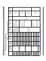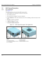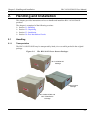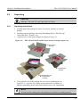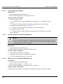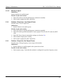
1
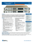
Belcom Microwaves Ltd.
Medium Power BUC
Models: BLC-10/20/25/40/50
User Manual
Manual P/N: MB1052, Revision 4.0
July 2013
Contacting Belcom Microwaves Ltd
The following information is provided for your use. Please feel free to contact us at Belcom
Microwaves Ltd.
Address:
Belcom Microwaves Ltd.
Ramat Gabriel Industry Park
P.O Box 907, Migdal Ha’emek, 23101
Israel
Phone:
(972) 4 6417600
Fax:
(972) 4 6417628
www.belcommicrowaves.com
Printed in Belcom Microwaves Ltd.
July 2013
Copyright
Copyright 2013 Belcom Microwaves Ltd. All rights reserved.
This manual has been published by Belcom Microwaves Ltd. and supplied on condition that it is
used solely for the purpose of supporting the operation, service, and maintenance of Belcom
Microwaves Ltd. equipment. Mutually accepted provisions of the contract with Belcom
Microwaves Ltd. will govern the rights of the customer with respect to this manual. This manual
shall not be duplicated, released, disclosed or used, in whole or in part, for any purpose other
than that stated herein, without the express written permission of Belcom Microwaves Ltd. The
contents of this document are subject to change without prior notice.
This document was designed and written by S.B.S. Technologies Ltd.
E-mail: [email protected]
Preface
BLC-10/20/25/40/50 User Manual
List of Revisions
No.
Date
Description
Page Number
1.0
September 2009
New Release
All
1.01
December 2009
- LH LED white color
- Addition of hazards
3-2
viii
2.0
June 2010
- Addition of 40W model
- Changes due to CE compliance
- Addition of AC operated modules
All
3.0
February 2013
- Addition of 50W model
- Technical updates
- Formatting
- Addition of 40 and 50 Watt DC models
- Addition of wide C band models
All
4.0
July 2013
- Technical updates
- Formatting
- Addition of Detectors Calibration Tables
(Appendix F)
- Updates of Assembly Kits
iii
BLC-10/20/25/40/50 User Manual
Preface
Table of Contents
iv
1.
Introduction
1.1
1.2
1.3
1.4
1.5
1.5.1
1.5.2
1.6
1.6.1
1.6.2
System Overview ........................................................................................................ 1-1
BUC Overview ............................................................................................................ 1-1
Features and Advantages............................................................................................. 1-2
Available Models and Configurations......................................................................... 1-3
BUC General Description ........................................................................................... 1-4
BLC-10/20/25 DC ....................................................................................................... 1-4
BLC-10/20/25/40/50 AC and BLC-40/50 DC ............................................................ 1-5
DC Power Inserter ....................................................................................................... 1-6
DC Power Inserter Overview ...................................................................................... 1-6
DC Power Inserter General Description...................................................................... 1-7
2.
Handling and Installation
2.1
2.1.1
2.1.2
2.1.3
2.1.4
2.1.5
2.2
2.2.1
2.3
2.3.1
2.3.2
2.3.3
2.3.4
2.3.5
2.4
Handling ...................................................................................................................... 2-1
Transportation ............................................................................................................. 2-1
Storage......................................................................................................................... 2-2
Return of Equipment ................................................................................................... 2-2
Equipment Damage or Loss ........................................................................................ 2-2
Receiving and Inspection ............................................................................................ 2-2
Unpacking ................................................................................................................... 2-3
Unpacking Instructions................................................................................................ 2-3
Installation ................................................................................................................... 2-4
BLC-10/20/25 DC Installation .................................................................................... 2-5
BLC-10/20/25/40/50 AC and BLC-40/50 DC Installation ......................................... 2-6
DC Power Inserter Installation .................................................................................... 2-7
BUC Powered by a DC Power Inserter via IFL Cable Connections........................... 2-7
BLC-10/20/25/40/50 AC and External DC Cable-Connection................................... 2-9
Post Installation Checks ............................................................................................ 2-11
3.
Maintenance
3.1
3.2
3.2.1
3.3
3.3.1
3.3.2
3.3.3
3.4
3.4.1
Preventive/Scheduled Maintenance Activities............................................................ 3-1
BUC Troubleshooting ................................................................................................. 3-2
BUC Indication Lights ................................................................................................ 3-2
BUC Possible Failures and Causes ............................................................................. 3-3
Problem: No Output Power ......................................................................................... 3-3
Problem / Suspicion: Low Output Power.................................................................... 3-5
Problem / Suspicion: No Output Power ...................................................................... 3-5
DC Power Inserter Troubleshooting............................................................................ 3-6
DC Power Inserter Indication Lights........................................................................... 3-6
Preface
BLC-10/20/25/40/50 User Manual
3.4.2
3.5
3.5.1
3.5.2
3.5.3
DC Power Inserter Possible Failures and Causes ....................................................... 3-6
Corrective Maintenance - Fan Replacement............................................................... 3-8
Replacement Parts....................................................................................................... 3-8
Tools and Materials..................................................................................................... 3-8
Procedure .................................................................................................................... 3-8
Appendix A: BLC-10/20/25 DC Models Packing List
Appendix B: AC Models Packing List
Appendix C: BLC-40/50 DC Packing List
Appendix D: DC Power Inserter Packing List
Appendix E: Control
Appendix F: Detectors Calibration Tables
Appendix G: BLC-40/50 DC Cable Assembly
Appendix H: AC Cable Assembly - L-Shape Plug
Appendix I: AC Cable Assembly - Straight Plug
Appendix J: Control Cable Assembly
Appendix K: BLC-10/20/25 DC Cable Assembly
Appendix L: BLC Technical Specifications
Index
v
BLC-10/20/25/40/50 User Manual
Preface
List of Figures
Figure 1-1:
Figure 1-2:
Figure 1-3:
Figure 1-4:
Figure 2-1:
Figure 2-2:
Figure 2-3:
Figure 2-4:
Figure 2-5:
Figure 2-6:
Figure 2-7:
Figure 2-8:
Figure 3-1:
Figure 3-2:
Figure 3-3:
BLC Family General View ................................................................................ 1-1
BUC General Description - BLC-10/20/25 DC................................................. 1-4
BUC General Description - BLC-10/20/25/40/50 AC and BLC-40/50 DC ...... 1-5
DC Power Inserter.............................................................................................. 1-7
The BLC & DC Power Inserter Packages.......................................................... 2-1
BLC-10/20/25/40/50 and DC Power Inserter Packages Open View ................. 2-3
BLC-10/20/25 DC Installation........................................................................... 2-5
BLC-10/20/25/40/50 AC and BLC-40/50 DC Installation................................ 2-6
BUC Powered by a DC Power Inserter via IFL Cable Connections ................. 2-8
Sealing the BUC Connectors using a Sealing Tape (example).......................... 2-8
BLC-10/20/25/40/50 AC and External DC Cable-Connection ....................... 2-10
BLC-10/20/25/40/50 AC and External DC Cable-Connection ....................... 2-11
Corrective Maintenance - Fan Replacement (Typical)...................................... 3-9
Corrective Maintenance - Fan Replacement for BLC-DC and BLC-20/25 AC
Models.............................................................................................................. 3-10
Corrective Maintenance - Fan Replacement for BLC-40 AC/DC and BLC-50
Models.............................................................................................................. 3-11
List of Tables
Table 1-1:
Table 3-1:
Table 3-2:
Table 3-3:
Table L-1:
Table L-2:
Table L-3:
Table L-4:
Table L-5:
Table L-6:
vi
Available Models and Configurations ............................................................... 1-3
BUC Indication Lights....................................................................................... 3-2
DCA Attenuation Levels.................................................................................... 3-7
IFL Cable Maximum Permitted Resistance ....................................................... 3-7
Electrical Specifications ....................................................................................L-1
Interfaces............................................................................................................L-3
BUC - Mechanical Specifications......................................................................L-4
Ambient Environmental Conditions ..................................................................L-4
Indicators............................................................................................................L-4
Protections..........................................................................................................L-4
Preface
BLC-10/20/25/40/50 User Manual
List of Acronyms and Abbreviations
1dBcp:
One dB Compression Point
Kg:
Kilogram
A:
Ampere
KHz:
Kilohertz
AC:
Alternate Current
L:
Length
BUC:
Block Up Converter
M&C:
Monitor & Control
C:
Celsius
MHz:
Megahertz
CIF:
Cost, Insurance, and Freight
NEC:
National Electrical Code
dB:
Decibel
OMT:
Ortho Mode Transducer
dBc:
Decibel (referenced to carrier)
PE:
Protective Earth
dBm:
decibel (referenced to 1 mWatt)
PLL:
Phase Locked Loop
DC:
Direct Current
PTP:
Peak to Peak
DCA:
Digital Controlled Attenuator
RF:
Radio Frequency
GHz:
Giga Hertz
RMA:
Return Material Authorization
GND:
Ground
SCPC:
Single Channel Per Carrier
H:
Height
VSAT:
Very Small Aperture Terminal
Hz:
Hertz
VSWR: Voltage Standing Wave Ratio
IF:
Intermediate Frequency
W:
IFL:
IF L-Band
Watts, Width
vii
BLC-10/20/25/40/50 User Manual
Preface
Safety Instructions Definitions
Définition des Consignes de Sécurité
WARNING
An operating procedure, practice, and so forth, which, if not correctly followed,
could result in personal injury or loss of life.
Handle this product only as instructed in this manual. Do not attempt to operate or
maintain this product in a manner not specifically stated in this manual.
AVERTISSEMENT
Manipuler ce produit uniquement selon les instructions de ce manuel.
Si le mode de fonctionnement ou l'utilisation n'est pas suivi correctement, cela peut
entraîner des blessures personnelles ou des dommages irréversibles.
Ne tentez pas d'exploiter ou d'entretenir ce produit d'une manière qui n'est pas
expressément indiquée dans ce manuel.
CAUTION
An operating procedure, practice, and so forth, which if not strictly observed,
could result in damage to or destruction of equipment.
AVERTISSEMENT
Si le mode de fonctionnement ou l'utilisation ne sont pas strictement observés, le
résultat pourrait entrainer des dommages ou la destruction de l'équipement.
NOTE
An operating procedure, practice, and so forth, which is recommended to highlight
for better work order or for efficiency.
NOTE
Une méthode de fonctionnement et d'utilisation recommandée et mise en évidence
pour meilleure séquence de travail et une meilleure efficacité.
viii
Preface
BLC-10/20/25/40/50 User Manual
General Safety Guidelines
The unit should be located in a Restricted Access Location (RAL) - access should be
allowed to service personnel only.
The unit is required to be connected to the earthing of the building structure. Grounding is
provided via the OMT waveguide flange and through the antenna pole. All 8 screws
connecting the unit to the OMT are to be securely tightened. The installer shall verify that
the antenna is bonded to the building structure ground.
The earthed side of the unit is connected to the shielding of the coax cable and the shielding
is should be earthed in the building infrustructure.
AC Supply
! use with a 10 A fuse/circuit-breaker.
! Only cables that are approved by the local agency and comply with the temperature and
power rating should be used.
! Power cable connection should be carried out only by authorized personnel as stated by
the local agency laws.
! Always use the correct power as labeled on the BUC.
DC Supply:
! Use +48V power supply (60V max) with output current limit of 5A, which complies
with CE safety requirements.
! Use local agency approved cable that complies with the temperature and power rating.
When servicing the BUC, obey all safety instructions related to transmitting antennas
maintenance.
Caution: hot surface while in operation, do not touch.
CAUTION
Always observe standard safety precautions during installation, operation and
maintenance of this product !
ix
Chapter 1: Introduction
1.
BLC-10/20/25/40/50 User Manual
Introduction
This chapter introduces Belcom Microwaves Ltd. Block Up Converters.
The chapter is comprised of the following sections:
Section 1.1: System Overview
Section 1.2: BUC Overview
Section 1.3: Features and Advantages
Section 1.4: Available Models and Configurations
Section 1.5: BUC General Description
Section 1.6: DC Power Inserter
1.1
System Overview
The BLC series BUC serves as an IF to RF converter and power amplifier in satellite
communication terminals.
A satellite communication terminal main parts are: a Block Up Converter (BUC), a Low Noise
Block down converter (LNB), a modem, an antenna, a feed and all the cables and accessories
that are required for the operation of the system.
This manual refers only to the BUC and the DC Power Inserter. The DC Power Inserter serves
as the power source of the DC models BUCs, which are powered via the IF L-Band (IFL) cable.
1.2
BUC Overview
The BLC products are high linearity Block Up Converters (BUC).
They serve in satellite communication systems and operate at the C frequency bands.
The BLC products are operated either using DC or AC power, applied via either the IFL cable
or a dedicated connector, depending on the model (See paragraph 1.3).
Figure 1-1:
BLC Family General View
BLC-40/50-AC/DC
BLC-10/20/25-DC
BLC-10/20/25-AC
1-1
BLC-10/20/25/40/50 User Manual
1.3
Chapter 1: Introduction
Features and Advantages
The BLC products features and advantages are:
An outdoor sealed unit
Operating temperature: -40"C to +55"C
Easy installation and operation
High reliability
Designed for either VSAT or SCPC applications
Can be mounted either on top or beneath the antenna boom
BLC-to-OMT flexible waveguide is available upon request
BLC powering available options:
! 90 - 230 VAC
! 48 (38 - 62) VDC via DC connector
! 48 (38 - 62) VDC via IFL cable (BLC-10/20/25 only)
! 24 (18 - 26) VDC via IFL cable (BLC-10 only)
Supported by Belcom Microwaves Ltd.
Optional Power Supply Configurations:
DC
Output Power [Watts]
10
20
25
40
50
AC Via external
Connector
Via IFL Cable*
Via External
Connector
-
* In case the modem is not capable of supplying the required power, a DC
Power Inserter (model A1007) is required for powering the BUC via the IFL
cable. The DC Power Inserter is connected between the modem and the BUC.
(see Figure 2-5 for cable connection instructions).
1-2
4.900
4.900
5.750
5.290
4.900
4.900
5.750
5.290
4.900
4.900
5.750
5.290
4.900
4.900
5.750
5.290
48VDC or
90-230VAC
48VDC
standard
24VDC or
90-230VAC
(optional)
DC via external
connector: optional
AC via external
connector
Or
DC via external
connector: optional
AC via external
connector
DC via IFL cableor
DC Via IFL cable:
standard.
DC Via external
connector: optional
Power Feed
Options
* See Appendix L: BLC Technical Specifications for complete specifications
950 - 1525 5.850 - 6.425
BLC-50
50
950 - 1825 5.850 - 6.725
BLWC-40
975 - 1275 6.725 - 7.025
1075 - 1435 6.365 - 6.725
BLPA-40
BLIN-40
950 - 1525 5.850 - 6.425
BLC-40
40
950 - 1825 5.850 - 6.725
BLWC-25
975 - 1275 6.725 - 7.025
1075 - 1435 6.365 - 6.725
BLPA-25
BLIN-25
950 - 1525 5.850- 6.425
BLC-25
25
950 - 1825 5.850 - 6.725
BLWC-20
975 - 1275 6.725 - 7.025
1075 - 1435 6.365 - 6.725
BLPA-20
BLIN-20
950 - 1525 5.850- 6.425
BLC-20
20
950 - 1825 5.850 - 6.725
975 - 1275 6.725 - 7.025
BLWC-10
BLIN-10
1075 - 1435 6.365 - 6.725
10
BLPA-10
4.900
Input
Voltage
Available Models and Configurations
Output
LO
Frequency Frequency
(GHz)
(GHz)
950 - 1525 5.850 - 6.425
Output Power
Input
@ P1dBcp Frequency
(W)
(MHz)
Table 1-1:
Available Models and Configurations
BLC-10
Model
1.4
Chapter 1: Introduction
Optional
M&C
AC: 400
DC: 380
AC: 230
12
1-3
AC - 12
AC: 190
DC: 210
DC - 7.2
DC: 170
DC: 90
AC: 100
Power
Weight
Consumption (Kg)
(W)
BLC-10/20/25/40/50 User Manual
BLC-10/20/25/40/50 User Manual
Chapter 1: Introduction
1.5
BUC General Description
1.5.1
BLC-10/20/25 DC
(See Figure 1-2)
The following items are located on the BUC outer surface:
1. Fan: Regulates the temperature of the BUC inner space.
2. J1: IF Input Connector
3. J3: External Power Supply Connector (optional)
4. L1, L2 Indicators: Three-state indicators (ON, OFF or blinking), indicate the status of the
BUC.
5. J2: M&C Connector (optional).
6. CPR137G Flange: RF output.
7. Ground Terminal Connection
Figure 1-2:
BUC General Description - BLC-10/20/25 DC
1
2 3
4
Legend:
5
7
6
5
4
3
2
1. Fan
5. J2 M&C Connector
2. J1 IF Input Connector
6. CPR137G Flange
3. J3 External Power Supply Connector 7. Ground Terminal Connection
4. L1, L2 Indicators
1-4
Chapter 1: Introduction
1.5.2
BLC-10/20/25/40/50 User Manual
BLC-10/20/25/40/50 AC and BLC-40/50 DC
(See Figure 1-3)
The following items are located on the BUC outer surface:
1. J4: External Power Supply Connector.
2. L3: AC/DC Power Indicator (Orange).
3. CPR137G RF Flange: RF output.
4. Ground Terminal Connection
5. J2: M&C Connector (optional).
6. L1, L2 Indicators: Three-state indicators (ON, OFF or blinking), indicate
the BUC status(see table 3-1, page 3-2).
7. J1: IF Input (IFL) Connector (N-Type): Modem or DC Power Inserter to
BUC cable connection.
8. Fan (not shown): Regulates the temperature of the BUC inner space.
Figure 1-3:
BUC General Description - BLC-10/20/25/40/50 AC and BLC-40/50 DC
1
Legend:
8
2
7
1. J4 External Power Supply Connector
2. L3 AC/DC Power Indicator
3. CPR137G RF Flange
4. Ground Terminal Connection
6
5
4
3
5. J2 M&C Connector (optional)
6. L1, L2 Indicators
7. J1 IF Input (IFL) Connector
8. Fan
1-5
BLC-10/20/25/40/50 User Manual
Chapter 1: Introduction
1.6
DC Power Inserter
1.6.1
DC Power Inserter Overview
The DC Power Inserter is an indoor unit that receives IF and 10 MHz signals from the modem,
combines them with DC power, which is required to power the BUC and delivers it to the BUC
via the IFL cable.
In any case, the DC Power Inserter blocks any possible DC voltage coming from the modem.
The total IF signal attenuation in the DC Power Inserter can be manually adjusted by the user,
using an internal DCA. The DCA does not influence the 10 MHz reference power level and the
DC supply.
A DC Power Inserter is required between the modem and the BUC, where the modem is not
capable of supplying the required DC power.
A 10 MHz internal reference option is available to be used where the modem does not provide
this signal.
NOTE
The DC Power Inserter is in use only with BLC-10/20/25 DC operated models (via
IFL)!
1-6
Chapter 1: Introduction
1.6.2
BLC-10/20/25/40/50 User Manual
DC Power Inserter General Description
(See Figure 1-4)
The following items are located on the DC Power Inserter outer surface:
1. ON/OFF Power Switch (illuminated): Switches the DC Power Inserter on
and off.
2. POWER SUPPLY Indicator (green): Indicates proper output voltage. The
indication turns off when output voltage is below 46V (With standard 48V
output voltage) or below 22V (With the 24V output voltage option).
3. HIGH CURRENT Indicator (red): Indicates output current higher than 6A.
4. LOW CURRENT Indicator (red): Indicates output current below 0.8A.
5. OUTPUT Connector: Provides IF, DC and 10 MHz reference to the BUC.
6. DCA Rotary Switch: Sets the internal IF attenuation.
7. INPUT Connector: IFL input from the modem.
8. AC INPUT Socket: Power line inlet.
Figure 1-4:
1
Legend:
2
3
1. ON/OFF Power Switch
2. POWER SUPPLY Indicator
3. HIGH CURRENT Indicator
4. LOW CURRENT Indicator
DC Power Inserter
4
5
6
7
8
5. OUTPUT Connector
6. DCA Rotary Switch
7. INPUT Connector
8. INPUT Connector
For additional detailed information about the DC Power Inserter refer to the DC Power Inserter
User Manual.
1-7
Chapter 2: Handling and Installation
2.
BLC-10/20/25/40/50 User Manual
Handling and Installation
This chapter provides instructions on how to handle and install the BLC-10/20/25/40/50
products.
The chapter is comprised of the following sections:
Section 2.1: Handling
Section 2.2: Unpacking
Section 2.3: Installation
Section 2.4: Post Installation Checks
2.1
Handling
2.1.1
Transportation
The BLC-10/20/25/40/50 may be transported by land, air or sea while packed in the original
package:
Figure 2-1:
The BLC & DC Power Inserter Packages
BLC-10/20/25-DC
Package
Power Inserter
Package
BLC-40/50-AC/DC and
BLC-10/20/25-AC
Package
2-1
BLC-10/20/25/40/50 User Manual
Chapter 2: Handling and Installation
2.1.2
Storage
While packed in its original package, the BLC-10/20/25/40/50 and DC Power Inserter may be
stored in the following conditions:
Temperature Range: 0 to 50"C
Relative Humidity: up to 95% (non-condensing)
2.1.3
Return of Equipment
NOTE
Do not return any equipment without areturn material authorization (RMA) number.
This is important for prompt and efficient handling of the returned equipment and of
the associated complaint.
When returning equipment to Belcom Microwaves Ltd. for repair or replacement:
1. Identify, in writing, the condition of the equipment.
2. Refer to the purchase order and the date the equipment was received.
3. Notify Belcom Microwaves Ltd. customer service department of the equipment condition
and obtain an RMA number and shipping instructions. Consult Belcom Microwaves Ltd.
customer service department for the best shipment method.
2.1.4
Equipment Damage or Loss
Belcom Microwaves Ltd. is responsible for damage or loss of equipment only if the purchase
order included a "door-to-door" delivery (Cost, Insurance, and Freight - CIF by INCOTERM).
Otherwise, contact the responsible transport carrier.
When declaring equipment as damaged during shipment, preserve the original shipping cartons
to facilitate inspection reporting.
Nevertheless, it is recommended to contact Belcom Microwaves Ltd. which will make an effort
to assist in any case of damage or loss of equipment.
2.1.5
Receiving and Inspection
CAUTION
Handle the BUC with extreme care. Excessive shock might damage the BUC.
The BUC is designed to function outdoors and will arrive in a standard shipping container.
Immediately upon receipt of the BUC, check the packing list against the actual equipment you
have received. Inspect the shipping containers exteriors for visible damage incurred during
shipping.
2-2
Chapter 2: Handling and Installation
2.2
BLC-10/20/25/40/50 User Manual
Unpacking
CAUTION
Mind the "This Side UP'' and "Open this End" labels.
2.2.1
Unpacking Instructions
1. Visually inspect the package for traces of excessive moisture or external
damage.
2. Carefully open the package, observing all handling labels ("This Side Up",
"Open This End", "Fragile", etc.).
3.
A general view of the open packages are shown in Figure 2-2:
Figure 2-2:
BLC-10/20/25/40/50 and DC Power Inserter Packages Open View
Power Inserter
Package
BLC-10/20/25-DC
Package
BLC-40/50-AC/DC and
BLC-10/20/25-AC
Package
4. Verify that all items in the packing list were received undamaged (see
Appendix A - Appendix D). If there are any omissions or evidence of
improper packaging, please notify Belcom Microwaves Ltd. immediately.
NOTE
Do not peel the sealing of the waveguide port. It is there for sealing the unit!
2-3
BLC-10/20/25/40/50 User Manual
2.3
Chapter 2: Handling and Installation
Installation
This section contains installation instructions of the following products:
Section 2.3.1: BLC-10/20/25 DC Installation
Section 2.3.2: BLC-10/20/25/40/50 AC and BLC-40/50 DC Installation
Section 2.3.3: DC Power Inserter Installation
Section 2.3.4: BUC Powered by a DC Power Inserter via IFL Cable Connections
Section 2.3.5: BLC-10/20/25/40/50 AC and External DC Cable-Connection
WARNING
Disconnect the unit from the mains before starting the installation. Failure to
comply could result in injury to personnel or damage the equipment!
WARNING
The equipment must be properly grounded according to the NEC and other local
safety code requirements. Failure to comply could result in personnel injury or loss
of life.
CAUTION
If the unit has the M&C option, make sure that the dust cover of the M&C
connector (J2) is properly closed when not in use.
CAUTION
It is essential to seal all the connectors on the BUC (i.e. the IF cable connector, the
power supply and the M&C) using a sealing tape (such as LeMark PN RT24 or
equivalent).
CAUTION
Verify that the cables are not bent or strained, especially near the connectors.
CAUTION
Verify that the cable-connectors are sealed and water draining along the cables
can’t penetrate into the connectors.
2-4
Chapter 2: Handling and Installation
2.3.1
BLC-10/20/25/40/50 User Manual
BLC-10/20/25 DC Installation
Fasten the BUC (1) to the boom using two mounting clamps (2), four hex nuts (4) and four
washers (3) as shown in Figure 2-3:
Figure 2-3:
BLC-10/20/25 DC Installation
2
1
3
Legend:
4
1. BLC-10/20/25W
2. Mounting Clamp (x2)
3. Flat Washer 1/4"-20x1 (x4)
4. Hex Nut 1/4"-20 with Lock (x4)
2-5
BLC-10/20/25/40/50 User Manual
2.3.2
Chapter 2: Handling and Installation
BLC-10/20/25/40/50 AC and BLC-40/50 DC Installation
(See Figure 2-4)
1. Mount four spacers (2) on the BUC(1) and fasten using four screws (3).
2. Mount the two lower Flanges (4) on the Spacers (2).
3. Attach four shafts (5) to the spacers (2) and fasten using the nut.
4. Attach the BUC to the boom using the two upper flanges (4) and fasten
using four nuts (6) and eight washers (7).
Figure 2-4:
BLC-10/20/25/40/50 AC and BLC-40/50 DC Installation
5
6, 7
4
4
2
1
Legend:
1. BLC
5. Shaft (x4; including Hex Nut 1/4"-20)
2. Spacer (x4) 6. Hex Nut 1/4"-20 with Lock (x8)
3. Screw (x4) 7. Flat Washer 1/4"-20x1 (x8)
4. Flange (x4)
2-6
3
Chapter 2: Handling and Installation
2.3.3
BLC-10/20/25/40/50 User Manual
DC Power Inserter Installation
CAUTION
Disconnect the unit from the mains before starting the installation.
1. Mount the DC Power Inserter onto a 19" rack.
2. Allow free air convection. Do not block the ventilation holes in the lower and upper face of
the unit.
2.3.4
BUC Powered by a DC Power Inserter via IFL Cable Connections
Connect the BUC and the DC Power Inserter as shown in Figure 2-5:
1. Connect the IF output of the modem to the INPUT connector of the DC
Power Inserter, using the coax cable (supplied with the DC Power Inserter).
2. Connect the OUTPUT of the DC Power Inserter to the input connector of the BUC (J1),
using an appropriate coax cable (not supplied).
3. Connect the BUC CPR137G output to the OMT, using an appropriate waveguide.
At the BUC side, use screw kit P/N A10559 (supplied).
4. At the OMT side, use screw kit P/N A11479(Supplied with the optional flexible
waveguide).
5. Connect the BUC GND point to the infrastructure ground, using a standard GND cable.
6. Connect the DC Power Inserter to the mains, using a standard power cable.
7. Seal all the connectors on the BUC, using a sealing tape (see Figure 2-6).
2-7
BLC-10/20/25/40/50 User Manual
Figure 2-5:
Chapter 2: Handling and Installation
BUC Powered by a DC Power Inserter via IFL Cable Connections
90-230VAC
Input
AC Cable
Cord
*
50 #$Coaxial Cable
to Modem
(1m long)
50/75 # Coaxial
Cable
GND
CPR137
RF Output
Legend:
Not supplied by Belcom
Supplied by Belcom
Figure 2-6:
2-8
GND
to Antenna
Sealing the BUC Connectors using a Sealing Tape (example)
Chapter 2: Handling and Installation
2.3.5
BLC-10/20/25/40/50 User Manual
BLC-10/20/25/40/50 AC and External DC Cable-Connection
1. Connect the IF output of the modem to the input connector of the BUC (J1),
using an appropriate coax cable (not supplied).
2. Connect the BUC CPR137G output to the OMT, using an appropriate waveguide.
At the BUC side, use screws kit P/N A10559 (supplied).
3. At the OMT side, use screws kit P/N A11479 (supplied with the optional flexible
waveguide).
4. Connect the BUC GND point to the infrastructure ground, using a standard GND cable.
5. AC powered unit: Connect the BUC AC input (J4) to the mains, using an appropriate AC
cable (connector supplied, cable assembly procedure in Appendix or Appendix ).
6. DC powered unit: Connect the BUC DC input (J3 for 10/20/25 Watt models, J4 for 40/50
Watt models) to the DC supply, using an appropriate DC cable (connector supplied, cable
assembly procedure in Appendix G: BLC-40/50 DC Cable Assembly or Appendix ).
7. Seal all the connectors on the BUC, using a sealing tape (see Figure 2-6).
2-9
BLC-10/20/25/40/50 User Manual
Figure 2-7:
Chapter 2: Handling and Installation
BLC-10/20/25/40/50 AC and External DC Cable-Connection
90-230VAC
Input
External
Indoor/Outdoor
Power Supply
to Modem
CPR137
RF Output
Legend:
Not supplied by Belcom
2-10
GND
to Antenna
Chapter 2: Handling and Installation
Figure 2-8:
BLC-10/20/25/40/50 User Manual
BLC-10/20/25/40/50 AC and External DC Cable-Connection
90-230VAC
Input
AC
GND
to Modem
CPR137 RF
Output
Legend:
Not supplied by Belcom
2.4
to Antenna
Post Installation Checks
1. Switch ON the modem, the DC Power Inserter and/or the indoor/outdoor
power supply (whatever is applicable).
2. Allow enough initialization time for the modem and make sure that the modem provides 10
MHz reference signal at the output, according to the modem instructions.
3. For a system with a DC Power Inserter: Verify that the POWER SUPPLY indicator, located
on the DC Power Inserter front panel, is ON and the HIGH CURRENT and LOW
CURRENT indicators are OFF.
4. BUC indicators:
For AC and 40/50 Watt DC models: Verify that the AC indicator is ON.
Verify that L1 (white) is ON and L2 (green) is ON.
5. Verify fan operation.
The system is now ready for transmission. In any case of malfunctioning, refer to chapter 3 for
troubleshooting.
2-11
Chapter 3: Maintenance
3.
BLC-10/20/25/40/50 User Manual
Maintenance
This chapter provides a list of procedures to be carried out while using the BLC-10/20/25/40/50.
The chapter includes the following sections:
Section 3.1: Preventive/Scheduled Maintenance Activities
Section 3.2: BUC Troubleshooting
Section 3.3: BUC Possible Failures and Causes
Section 3.4: DC Power Inserter Troubleshooting
Section 3.5: Corrective Maintenance - Fan Replacement
WARNING
When servicing the BUC, follow all safety instructions related to transmitting
antennas maintenance.
3.1
Preventive/Scheduled Maintenance Activities
Perform the following annually:
1. Verify that all connectors are properly sealed.
2. Verify fan rotation and free airflow.
3-1
BLC-10/20/25/40/50 User Manual
Chapter 3: Maintenance
3.2
BUC Troubleshooting
3.2.1
BUC Indication Lights
There are three LED indicators on the BUC (Two LED indicators in BLC 10/20/25-DC ).
L3 LED in the AC Powered BUCs and BLC 40/50-DC) indicates that the BUC receives input
supply power.
Table 3-1 explains the functions of the BUC indication lights.
Table 3-1:
L1 (White)
3-2
BUC Indication Lights
L2 (Green/Red)
Indication
ON
Green
Normal operation
ON
Red 1 Hz blinks
The BUC is muted
OFF
Red
10 MHz reference power level below minimum
OFF
OFF
Input DC supply voltage below minimum Or
Internal power supply fault
ON
Green 1 Hz blinks External power supply or modem overload
ON
Red 5 Hz blinks
BUC temperature is above the maximum allowed
value. The BUC shuts down automatically and
resume operation after 10 minutes
ON
Red
Missing or instable 10 MHz reference frequency
Or
Internal fault
ON
Red 2 blinks
Fan fault (BLC-40/50 S/N 200 and above)
ON
Red 3 blinks
High reflected power (with M&C option only)
Chapter 3: Maintenance
3.3
BLC-10/20/25/40/50 User Manual
BUC Possible Failures and Causes
NOTE
If a unit is suspected as malfunctioning, it is recommended to replace it with a
serviceable one (if available), using the same cables and position. This action will
indicate whether the fault is in the unit or in another part of the system.
3.3.1
Problem: No Output Power
List of Possible causes:
Missing Power Supply
Power Supply Low Voltage
Internal Temperature Protection Activated
Missing, Low or Unstable 10 MHz Reference
Missing IF Signal
Check the indication of each of the possible causes and act according to the instructions as
described below:
3.3.1.1
Missing Power Supply
Indications:
System (modem or control center) indicates no uplink signal.
BUC indication lights L1, L2 are OFF.
BUC surface temperature remains low after 15 minutes.
Fan is not rotating.
Further checks and remedy:
Models with DC supplied via the IFL cable:
! Check IFL cable connection (see Section 3.3.1.5).
! Verify that DC Power Inserter is ON and in normal operation (whenever
applicable).
! Verify DC voltage (24 or 48 VDC) at the IFL cable end (BUC side).
Modules with external AC/ DC supply:
! Check DC or AC supply.
! Check power supply cable connections.
If the power supply and its connections are OK, then replace the BUC.
3-3
BLC-10/20/25/40/50 User Manual
3.3.1.2
Chapter 3: Maintenance
Power Supply Low Voltage
Indications:
System indicates no uplink signal.
BUC indication lights: L1 off, L2 blinks at 1 Hz.
Further checks and remedy:
IFL DC supply models:
! Check DC Power Inserter indications (see Section 3.4) or modem DC power
rating.
! Check IFL cable specified DC resistance and make sure it is below the
maximum recommended value (see Table 3-3).
! Check IFL cable for breaks and improper connectors assembly.
External DC supply models:
! Check DC power supply. If the power supply and its connectors are in order,
replace the BUC.
3.3.1.3
Internal Temperature Protection Activated
NOTE
Excessive ambient temperature might trigger the temperature protection: if for any
reason the BUCs temperature exceeds 85°C, the BUC shuts down automatically for
10 minutes and then turns ON again.
Indications:
System indicates no uplink signal.
BUC indication lights: L1 on, L2 red blinks at 5 Hz.
Further checks and remedy:
Let the unit cool down for 15 minutes.
If possible, prevent direct sun radiation on the unit.
Verify fan rotation, replace fan if necessary.
3.3.1.4
Missing, Low or Unstable 10 MHz Reference
Indications:
System indicates no uplink signal.
BUC indication lights: L1 – OFF,L2 - red.
BUC surface temperature remains low after 15 minutes.
Further checks and remedy:
Check modem setup. Make sure modem is configured to provide a reference signal.
3-4
Chapter 3: Maintenance
3.3.1.5
BLC-10/20/25/40/50 User Manual
Missing IF Signal
Indications:
System indicates no uplink signal.
Further checks and remedy:
Check IFL cable for breaks and improper connectors assembly.
Check indoor equipment cable connection.
3.3.2
Problem / Suspicion: Low Output Power
Possible cause: Low IF input level
Indications:
System indicates low uplink power.
Further checks and remedy:
Check IFL cable for breaks and improper connectors assembly.
Check IFL cable specified attenuation. Assure proper IF level at the IF connector (BUC
side).
Check DC Power Inserter attenuation settings (see Section 3.4).
Check modem output power setting.
Check indoor equipment cable connections.
3.3.3
Problem / Suspicion: No Output Power
Possible cause: Wrong frequency sense setup in the modem.
Indications:
System indicates no uplink signal or the system do not lock.
Further checks and remedy:
Check modem setup. Verify that the modem is configured for positive frequency sense.
3-5
BLC-10/20/25/40/50 User Manual
Chapter 3: Maintenance
3.4
DC Power Inserter Troubleshooting
3.4.1
DC Power Inserter Indication Lights
POWER SUPPLY - Indicates proper output voltage. Turns off when output voltage is below
46V (with standard 48V output voltage) or below 22V (with the 24V output voltage option).
LOW CURRENT - Indicates output current below 0.8A - The BUC do not draw current
from the DC Power Inserter.
HIGH CURRENT - Indicates output current higher than 6A.
3.4.2
DC Power Inserter Possible Failures and Causes
3.4.2.1
Problem: No Output Voltage
Possible cause: Missing AC supply
Indications:
POWER SUPPLY indication - OFF
Power switch light - OFF
Further checks and remedy:
Turn power switch on.
Check AC supply.
3.4.2.2
Problem: Low Output Voltage
Possible cause: BUC draws excessive current or short in the IFL cable or connectors
Indications:
POWER SUPPLY indication - OFF
HIGH CURRENT - ON
Further checks and remedy:
Check IFL cable for shorts
Check BUC
3-6
Chapter 3: Maintenance
3.4.2.3
BLC-10/20/25/40/50 User Manual
Problem: Low Output Voltage
Possible cause: Internal failure
Indications:
Power switch light - ON, POWER SUPPLY indication - OFF
Further checks and remedy:
Replace DC Power Inserter
3.4.2.4
Problem: Low or Zero Output Current
Possible cause: IFL cable disconnected or BUC failure
Indications:
POWER SUPPLY indication - ON
LOW CURRENT - ON
Further checks and remedy:
Check IFL cable for shorts
Check BUC
3.4.2.5
Problem: No IF Output Power or Low IF Output Power from the DC Power Inserter
Possible cause: High IF attenuation in the DC Power Inserter or wrong cable connections.
Indications:
System indicates missing or low uplink signal
Further checks and remedy:
Check cable connections
Using a screwdriver, gradually decrease the attenuation, using the ATT rotary switch and the
table below.
Position
Attenuation [dB]
0
0
1
2
Table 3-2:
DCA Attenuation Levels
2 3 4
5
6
7
8
9
A
4 6 8 10 12 14 16 18 20
Table 3-3:
B
22
C
24
D
26
E
28
F
30
IFL Cable Maximum Permitted Resistance
Model
DC Max. Power
Consumption (W)
Min. Input Voltage to
the BUC(V)
* Cable Max.
Resistance (#)
10 W
95
38
4
10 W 24V
95
18
1.3
20 W
170
38
2.2
25 W
210
38
1.8
40/50 W
380
38
* A summing of both center conductor and shielding resistance.
1.0
3-7
BLC-10/20/25/40/50 User Manual
3.5
Corrective Maintenance - Fan Replacement
3.5.1
Replacement Parts
For BLC-10/20/25 AC&DC Fan with Cable: P/N A1052-FAN-1
For BLC-40/50 AC&DC Fan with Cable: P/N 1143-FAN-1
3.5.2
Tools and Materials
Philips screwdriver
Open wrench
3.5.3
Procedure
1. Preparations:
a. Pending on your configuration, switch OFF the modem, the DC
Power Inserter and/or the indoor/outdoor power supply.
Chapter 3: Maintenance
b. Disconnect all BUC cables.
c. Dismantle the BUC.
NOTE
The replacement work should be performed in a clean area and on an appropriate
workbench.
2. Remove the fan cover (1):
a. Remove four screws (2) and spring washers (3) fastening the Cover
to the chassis.
b. Carefully open the cover and disconnect the fan cable-connector (4).
3-8
Chapter 3: Maintenance
Figure 3-1:
BLC-10/20/25/40/50 User Manual
Corrective Maintenance - Fan Replacement (Typical)
4
1
3
2
Legend:
1. Fan Cover
2. Screw NF10-32x PH.P, (x4)
3. Spring Washer, #10 (x4)
4. Fan Cable-Connector
3-9
BLC-10/20/25/40/50 User Manual
Chapter 3: Maintenance
3. BLC-DC and BLC-20/25 AC Models Fan Removal:
a. While holding the four nuts (5) using an open wrench, remove the
four screws (6) and washers (7), fastening the fan (8) to the cover.
b. Remove the fan (8), the screws (6), the washers (7) and the nuts (5)
from the cover.
Figure 3-2:
Corrective Maintenance - Fan Replacement for BLC-DC and BLC-20/25 AC Models
6
7
5
8
Legend:
5. Nut M4 st (x4)
6. Screw M4x16mm (x4)
7. Washer (x4)
8. Fan Including Cable
3-10
Chapter 3: Maintenance
BLC-10/20/25/40/50 User Manual
4. BLC-40AC/DC and BLC-50 Models Fan Removal:
a. While holding the four nuts (5) using an open wrench, remove the
four screws (6), fastening the fan (7) and the finger guard (8).
b. Remove the fan (7), the screws (6), the finger guard (8) and the nuts
(5) from the cover.
Figure 3-3:
Corrective Maintenance - Fan Replacement for BLC-40 AC/DC and BLC-50 Models
7
5
8
Legend:
6
5. Nut M4 st (x4)
6. Screw M4x16mm (x4)
7. Fan Including Cable
8. Finger Guard
5. Mount a new fan in a reversed order.
6. Install the BUC(see either Section 2.3.1 or Section 2.3.2).
7. Pending on your configuration, re-connect the BUC cables (see Sections 2.3.4 - 2.3.5).
8. Operate the BUC(see Section 2.4: Post Installation Checks).
3-11