1
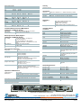
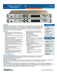
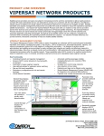
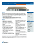
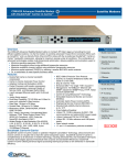
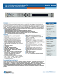
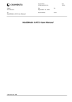
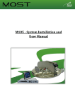
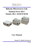
Modems CDM-570/L & CDM-570/L-IP Satellite Modems Overview Typical Users The CDM-570 and the CDM-570L are Comtech EF Data’s entry-level satellite modems that provide industry leading performance and flexibility in a 1 RU package at a very competitive price. Designed to address the market for low-cost terminals, the modems are available with 70/140 MHz or L-Band IF and EIA-530/-422, V.35, EIA-232 and G.703 data interfaces. An optional Internet Protocol (IP) Module with 10/100Base-T Ethernet port is available for IP-centric applications. For cellular backhaul, the CDM-570/L and CDM-570/LIP also offer E1 RAN Optimization as an option. Automatic Uplink Power Control (AUPC) Features Embedded Distant-end Monitor and Control Data rate range from 2.4 kbps to 9.98 Mbps (EDMAC/EDMAC2) CDM-570 & CDM-570-IP: 50 to 90 or 100 to 180 Redundancy options MHz IF range CDM-570 & CDM-570-IP: FSK CDM-570L & CDM-570L-IP: 950 to 2000 MHz IF communications to CSAT-5060 or range KST-2000A Modulation types: BPSK, QPSK, OQPSK, 8-PSK, CDM-570L & CDM-570L-IP: 10 MHz reference Patented 8-QAM, 16-QAM for BUC, FSK communications and optional Forward Error Correction (FEC) choices include BUC power supply Turbo Product Code (TPC), Viterbi, Reed CDM-570L & CDM-570L-IP: 10 MHz reference Solomon, and Trellis Coded Modulation (TCM) and power supply for LNB Data Interfaces: EIA-422/530, V.35, G.703 T1/E1 Optional, integrated IP Module with (option), 10/100Base-T Ethernet (option) 10/100Base-T Ethernet port (CDM-570-IP and Standards based management via SNMP, Web, CDM-570L-IP) or Telnet Static IP routing for unicast and multicast Symmetric as well as asymmetric operation for Header and payload compression for maximum bandwidth efficiency maximum efficiency Support for mesh, star and hybrid network IGMP v1 and v2 topologies VLAN capability with 802.1Q compliant E1 RAN Optimization (option) QoS G.703 clock extension for IP backhaul (option) Vipersat Management System (VMS) Fast acquisition demodulator ( 32 kHz integration acquisition range, 64 kbps, Rate 1/2 QPSK: 150 ms average) • Enterprise • Internet Service Providers • Satellite Service Providers • Offshore & Maritime • Mobile Operators Common Applications • Cellular Backhaul • Communications onthe-Move • Disaster Recovery & Emergency Communications • Enterprise • Offshore & Maritime Communications • Satellite News Gathering Turbo Product Coding The optional Turbo Product Codec delivers significant performance improvement when compared to Viterbi with concatenated ReedSolomon. It offers increased coding gain, lower decoding delay, and significant bandwidth savings compared to traditional FEC. EDMAC & AUPC Operation The CDM-570/L-IP has the ability to monitor and control the distant end of a point-to-point satellite link using EDMAC or EDMAC2. User data is framed and bits are added to pass control, status, and AUPC information. This is transparent to the user. www.comtechefdata.com Management The modems support SNMP, web-based and command line interfaces for management. The modems can also be configured and monitored from the front panel, or through the remote M&C port (for non-IP mode of operation). Ten complete RF configurations may be stored in the modem. An event log stores alarm and status information in non-volatile RAM, while the link statistics log stores link performance (Eb/No and AUPC performance) for monitoring and reporting purposes. E1 RAN Optimization (Point-to-Point) Comtech EF Data’s RAN Optimization technology significantly reduces the WAN (satellite) bandwidth required to carry an E1 bearer used for cellular backhaul. It provides the user complete control over the desired level of optimization and link quality. Depending on the traffic profile, typical bandwidth reduction of 30-35% can be achieved with little or no impact to the voice quality. The WAN bandwidth can be reduced by as much as 60% relative to the ingress data rate, allowing users to achieve desired bandwidth savings and voice quality. The CDM-570/L provides usage statistics to assist with link monitoring. E1 RAN optimization cannot be used simultaneously with the IP Module. G.703 Clock Extension Cellular networks require precise synchronization of base stations, which is a challenge when using IP backhaul. Most operators are forced to use GPS-based external equipment for site synchronization. CDM-570/L-IP offers a G.703 clock extension option that propagates a high stability reference from hub to the remote. This process does not require additional bandwidth. FAST Feature Enhancements The FAST codes make it easy to upgrade the modem capability in the field. New features can be added on site, using FAST access codes purchased from Comtech EF Data that can be entered via the front panel. IP Module With its innovative architecture and support for advanced capabilities, IP Module-equipped versions of the CDM-570/L allow for efficient IP networking and transport over satellite. The CDM-570/L-IP supports a wide range of applications and network topologies. Header Compression Option Configurable on a per route basis, header compression reduces the bandwidth required for VoIP by as much as 60%. Example: A G.729 voice codec, operating at 8 kbps, requires 32 kbps bandwidth once encapsulated into an IP/UDP/RTP frame. With compression, the same voice call needs only 10.8 kbps total WAN satellite bandwidth. Typical Web/HTTP traffic can also be reduced by 10% via IP/TCP header compression. Payload Compression Option Configurable on a per route basis, payload compression can reduce the required satellite bandwidth by up to 40%. Quality of Service (QoS) Option The modems support multi-level QoS to reduce jitter and latency for real time traffic, provides priority treatment to mission critical applications and allows non-critical traffic to use the remaining bandwidth. Supported modes are: DiffServ – Industry-standard method of providing QoS enabling seamless co-existence in networks that implement DiffServ. Max/Priority – Provides eight levels of traffic prioritization with the ability to limit maximum traffic per priority class Min/Max – Provides a Committed Information Rate (CIR) to each user defined class of traffic with the ability to allow a higher burstable rate depending on availability Vipersat Management System Dynamic SCPC carrier allocation & true bandwidth-on-demand User-defined policies for upstream carrier switching Star and full mesh capabilities using single hop on-demand Advanced switching takes advantage of using other modulation/forward error correction combinations Guaranteed bandwidth capability VMS Network & Bandwidth Management A Vipersat-powered network integrates these advanced modems with a powerful network management tool, the Vipersat Management System (VMS). In addition to the traditional monitoring and control of the CDM-570/L-IP modems and the CDD-564/L and CDD-562L demodulators, the VMS allows these devices to share bandwidth, and when needed, switch automatically to a dedicated SCPC channel. In a Vipersat-powered network, the CDM-570/L-IP modem takes advantage of its fast acquisition demodulation to allow it to operate in a shared mode. Inbound transmissions (from remote to hub) can be switched from a shared Selective Time Division Multiple Access (STDMA) mode to a dedicated Single Carrier Per Channel (SCPC) connection via a variety of user defined policies or triggers. This enables the network to more effectively handle real-time connection-oriented applications and reduces both latency and network congestion. Through VMS, dynamic point-to-point mesh connections can also be established between remotes. Upstream Switching Through protocol classification in the remote terminals, the modem initiates automatic switching. VMS establishes dSCPC bandwidth based on policies that can be individually enabled on a per-remote basis, or globally enabled. Policies can be configured for a variety of applications such as VoIP, video (VTC), or based on a load, or via a schedule, Type of Service (ToS), or QoS rules such as IP port or IP address and protocol type. Operators are able to set minimum and maximum data rates for each remote as well as excess data rates for an initial upstream switch. Vipersat Operation Mode Vipersat operation is enabled via a FAST feature code. Networks can easily start off in point-to-point or point-to-multipoint configurations. As the network grows and users wish to take advantage of the bandwidth on-demand savings by implementing a Vipersat network, modems can easily be upgraded to Vipersat mode. Vipersat mode provides for the ability to operate in the following modulation/FEC rates: STDMA SCPC QPSK, Rate 3/4 Turbo FEC – all STDMA modes Data Rate Range: 64 kbps – 4.5 Mbps BPSK, Rate 5/16 Turbo FEC – Entry Channel Mode only Data Rate Range: 32 kbps to 937 kbps All Turbo Product Code FEC rates as detailed in the following specifications Specifications CDM-570 & CDM-570-IP: 50 to 90 or 100 to 180 MHz, 100 Hz resolution CDM-570L & CDM-570L-IP: 950 to 2000 MHz, 100 Hz resolution Data Interfaces EIA-422/-530 DCE, V.35 DCE, Sync EIA-232, 10/100Base-T Ethernet (option), G.703 T1 balanced (option), G.703 E1 balanced or unbalanced (option) Data Rate Range 2.4 kbps to 9.98 Mbps (depending on modulation, (See user manual for FEC and framing), 1 bps step with fully independent details) TX and RX rates Modulation & FEC Data Rate Range 5/16 BPSK TPC 2.4 kbps to 0.937 Mbps 21/44 BPSK TPC 2.4 kbps to 1.430 Mbps 1/2 BPSK 2.4 kbps to 1.500 Mbps 1/2 QPSK/OQPSK 4.8 kbps to 3.000 Mbps 3/4 QPSK/OQPSK 7.2 kbps to 4.500 Mbps 7/8 QPSK/OQPSK 8.4 kbps to 5.250 Mbps 2/3 8-PSK TCM 8.7 kbps to 4.400 Mbps 21/44 QPSK/OQPSK TPC 4.8 kbps to 2.860 Mbps 3/4 QPSK/OQPSK TPC 7.2 kbps to 4.500 Mbps 7/8 QPSK/OQPSK TPC 8.4 kbps to 5.250 Mbps 0.95 QPSK/OQPSK TPC 9.1 kbps to 5.666 Mbps 3/4 8-PSK/8-QAM TPC 10.8 kbps to 6.750 Mbps 7/8 8-PSK/8-QAM TPC 13.6 kbps to 7.875 Mbps 0.95 8-PSK/8-QAM TPC 15.3 kbps to 8.500 Mbps 3/4 16-QAM TPC 14.4 kbps to 9.000 Mbps 7/8 16-QAM TPC 16.8 kbps to 9.980 Mbps Uncoded BPSK 4.8 kbps to 3.000 Mbps Uncoded QPSK/OQPSK 9.6 kbps to 5.000 Mbps Note: Data rate specifications reflect CDM-570/L or CDM-570/L-IP modem operating in non-Vipersat mode Scrambling Mode dependent – ITU V.35, or proprietary externally synchronized FEC Options Viterbi Rate 1/2 BPSK, QPSK/OQPSK Rate 3/4 and 7/8 QPSK/OQPSK and 16-QAM w/RS TCM 8-PSK 2/3 (Closed network – not IESS-310) Turbo Product Coding Rate 21/44 BPSK, 5/16 BPSK, Rate 21/44 QPSK/OQPSK Rate 3/4 and Rate 7/8 QPSK/OQPSK, 8-PSK/8-QAM and 16-QAM Rate 0.95 QPSK/OQPSK and 8-PSK/8-QAM Reed-Solomon Proprietary 220/200 and 200/180 modes available Uncoded BPSK, QPSK/OQPSK M&C Interface EIA-232, EIA-485 (2- or 4-wire), Ethernet 10/100Base-T (dependent on operational mode) Input/Output Impedance CDM-570 & CDM-570-IP: matched for 50/75 , BNC connector CDM-570L & CDM-570L-IP: transmit and receive 50 , female Type N connector External Reference Input 1, 2, 5, 10 or 20 MHz, BNC connector Form C Relays TX, RX traffic alarms and unit faults Modulator Frequency Range Frequency Stability Output Power Accuracy Phase Noise Output Spectrum/ Filtering Harmonics and Spurious Transmit On/Off Ratio External TX Carrier Off TX Clock Options CDM-570 & CDM-570L & CDM-570-IP CDM-570L-IP 1 ppm, 0º to 50ºC 0.06 ppm, 0º to 50ºC (32º to 122ºF) (32º to 122ºF) 0 to –25 dBm, 0.1 dB 0 to –40 dBm, 0.1 dB steps steps 0.5 dB over frequency 1.0 dB over frequency and temperature and temperature < 0.75 degrees RMS < 1.2 degrees RMS double-sided, double-sided, 100 Hz to 1 MHz 100 Hz to 1 MHz Meets IESS-308/-309 power spectral mask -55 dBc/4 kHz (typically < -60 dBc/4 kHz) 55 dB minimum By TTL LOW signal, or RTS Internal (SCT), external (TT), loop timing with symmetric or asymmetric operation (data interface dependent) Demodulator Input Power Range Max Composite Level Acquisition Range Acquisition Time Receive Buffer Receive Clock Options Clock Tracking Monitor Functions CDM-570 & CDM-570-IP -30 to -60 dBm CDM-570L & CDM-570L-IP -130 + 10 log symbol rate, dBm (minimum) -90 + 10 log symbol rate, dBm (maximum) +35 dBc, up to +40 dBc, up to -5 dBm absolute max. -10 dBm absolute max. 1 to 32 kHz, 1 to 32 kHz, 1 kHz step 1 kHz step, symbol rate <= 625 ksps 1 to 200 kHz, 1 kHz step, symbol rate > 625 ksps Highly dependent on data rate, FEC rate, and demodulator acquisition range. Example: 120 ms average at 64 kbps, Rate 1/2 QPSK, ± 10 kHz acquisition sweep range, 6dB Eb/No 512, 1024, 2048, 4096, 8182, or 16384 bits Buffer disabled (RX satellite), buffer enabled (symmetric or asymmetric operation) (data interface dependent) 100 ppm minimum Eb/No, frequency offset, BER, buffer fill status, RX signal level Example BER Performance For symbol rates up to 2.5 Msps (See user’s manual for higher symbol rates). Guaranteed Eb/No, in dB (typical values in parentheses) with two adjacent carriers 7 dB higher. (See the user’s manual for a complete listing of the performance of all FEC types, code rates, and modulation types.) Viterbi BPSK, 1/2 3/4 7/8 QPSK/OQPSK 10-5 5.4 (4.9) 6.8 (6.3) 7.7 (7.2) 10-7 6.7 (6.2) 8.2 (7.7) 9.0 (8.6) Viterbi & Concatenated Reed-Solomon 220/200 or 200/180 BPSK, 1/2 3/4 7/8 QPSK/OQPSK -5 10 4.3 (4.0) 5.6 (4.7) 6.5 (6.0) 10-7 4.5 (4.2) 6.0 (5.2) 6.9 (6.5) Turbo Product Codec BPSK 5/16 10-6 2.4 (2.1) 10-7 2.6 (2.3) 10-8 2.7 (2.4) QPSK/OQPSK 21/44 -6 10 2.9 (2.6) -8 10 3.3 (2.8) 8-PSK 3/4 10-6 6.2 (5.8) 10-8 6.8 (6.3) 8-QAM 3/4 -6 10 6.5 (6.1) -8 10 7.2 (6.8) 16-QAM 3/4 -6 10 7.4 (7.0) 10-7 7.8 (7.3) 10-8 8.2 (7.7) Security 21/44 2.8 (2.5) 3.1 (2.8) 3.3 (2.9) 3/4 3.8 (3.4) 4.4 (4.0) 7/8 7.0 (6.6) 7.2 (6.8) 7/8 6.6 (6.2) 6.8 (6.4) 7/8 8.1 (7.7) 8.2 (7.8) 8.3 (7.9) Password protection Access list 7/8 4.3 (4.0) 4.5 (4.2) 0.95 9.3 (8.9) 10.3 (9.9) 0.95 9.6 (9.2) 10.6(10.2) Accessories 0.95 6.4 (6.0) 6.9 (6.5) CRS-170A CRS-180 CRS-280 CRS-280L CRS-300 Regulatory CE Mark FCC Approval +13, +18, and +24 VDC @ 500 mA maximum 10 MHz via RX center conductor, -3 dBm ± 3 dB Block Up Converter (BUC) Support (CDM-570L & CDM-570L-IP Only) BUC Voltage BUC Reference FSK Support 24 VDC, 90 W @ 50°C, 100 W @ 30°C (internally fitted option) 48 VDC, 150 W @ 50°C, 180 W @ 30°C (internally fitted option, not available with -24 VDC input) 10 MHz via TX center conductor, 0 dBm ± 3 dB Via TX center conductor with FSK BUCs Environmental & Physical Temperature Power Supply Power Consumption (See Manual) Dimensions (height x width x depth) Weight Operating: 0 to 50ºC (32 to 122ºF) Storage: -25 to 85ºC (-13 to 185ºF) 100 to 240 VAC, 50/60 Hz -24 VDC (HW option) -48 VDC (HW option) CDM-570: 29 W typical (32 W max.) CDM-570-IP: 37 W typical CDM-570L: 29 W typical (32 W max.) w/o BUC CDM-570L-IP: 37 W typical w/o BUC CDM-570-IP: 1.75” x 19” x 12” (4.4 x 48.3 x 30.5 cm) CDM-570L-IP: 1.75” x 19” x 16” (4.4 x 48.3 x 40.6 cm) CDM-570 & CDM-570-IP: 6 lbs (2.7 kg) CDM-570L: 7 lbs (3.2 kg) (without BUC P/S) CDM-570L & CDM-570L-IP: 16 lbs (7.2 kg) including 150 W BUC power supply Operations & Maintenance Configuration and Management EMC, Safety (CDM-570 & CDM-570-IP) EN55022 Class B (Emissions) EN50082-1 Part 1 (Immunity) EN60950 (Safety) (CDM-570L & CDM-570L-IP) FCC Part 15 Class B (CDM-570L & CDM-570L-IP) Available Options Low-Noise Block Converter (LNB) Support (CDM-570L & CDM-570L-IP Only) LNB Voltage LNB Reference CDM-570L & CDM-570L-IP: 1:1 Modem Redundancy IF Switch CDM-570 & CDM-570-IP: 1:1 Modem Redundancy IF Switch CDM-570: 1:N Modem Redundancy IF Switch Module CDM-570L: 1:N Modem Redundancy IF Switch Module CDM-570 & CDM-570L: 1:10 Modem Redundancy Switch Front panel Remote port – EIA-232 or EIA-485 (2- or 4-wire) SNMP with MIB II and private, modem-specific MIB Telnet Web browser (HTTP) Console interface (EIA-232, RJ-12 connector) Software/firmware upgrade via FTP IP traffic statistics Faults and alarms Configuration backup and restoral How Enabled FAST FAST FAST FAST FAST FAST Hardware Hardware Hardware Hardware Hardware Hardware Hardware Hardware Hardware Hardware FAST FAST FAST FAST Option Variable rate to 2.048 Mbps Variable rate to 5 Mbps Variable rate to 9.98 Mbps 8-PSK, 8-QAM modulation (8-QAM with TPC only) 16-QAM modulation G.703 clock extension (requires G.703 E1/T1 interface option) G.703 E1/T1 interface Reed-Solomon Codec board Turbo Codec board E1 RAN Optimization (Requires G.703 E1/T1 interface option) Power supply, AC input Power supply, -24 VDC input Power supply, -48 VDC input 24 VDC, 90 W @ 50°C (100 W @ 30°C) BUC power supply, AC input, -24 or -48 VDC input 48 VDC, 150 W @ 50°C (180 W @ 30°C) BUC power supply, AC input or 48 VDC input IP Module IP Module Options: Header compression Payload compression Quality of Service (QoS) – 3 modes Vipersat Management System Integration Networking Protocols RFC 768 – UDP RFC 791 – IP RFC 792 – ICMP RFC 793 – TCP RFC 826 – ARP RFC 856 – Telnet RFC 862 – Ping RFC 894 – IP RFC 959 – FTP RFC 1112 – IP Multicast RFC 1213 – SNMP MIB II RFC 1812 – IPv4 Routers RFC 2045 – MIME RFC 2236 – IGMP v2 RFC 2474 – Diffserv RFC 2475 – Diffserv RFC 2578 – SMI RFC 2597 – AF PHB RFC 2598 – Expedite Forwarding RFC 2616 – HTTP RFC 2821 – SMTP RFC 3412 – SNMP RFC 3416 – SNMPv2 RFC 3418 – SNMP MIB CDM-570/L-IP Satellite Modem back panel 2114 West 7th Street, Tempe, Arizona 85281 USA Voice: +1.480.333.2200 ● Fax: +1.480.333.2540 ● Email: [email protected] U.S. Patent 7,254,188 Comtech EF Data reserves the right to change specifications of products described in this document at any time without notice and without obligation to notify any person of such changes. Information in this document may differ from that published in other Comtech EF Data documents. Refer to the website or contact Customer Service for the latest released product information. © 2011 Comtech EF Data ds-cdm570-IPEN_570L-IP.docx 7/22/2011