1
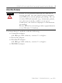
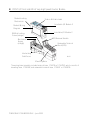
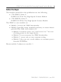
Installation Instructions
POINT I/O 5V dc and 24V dc Very High Speed
Counter Module
Catalog Numbers 1734-VHSC5 and 1734-VHSC24, Series C
Inside . . .
For
See Page
Important User Information
2
Preventing Electrostatic Discharge
3
Environment and Enclosure
4
European Hazardous Location Approval
5
North American Hazardous Location Approval
6
About the Modules
7
Before You Begin
9
Install the Mounting Base
10
Install the Module
11
Install the Removable Terminal Block (RTB)
13
Remove a Mounting Base
14
Wire the Module
15
Configure the Module
16
Troubleshooting
26
Specifications
29
Additional Resources
34
Publication 1734-IN003E-EN-E - June 2005
2 POINT I/O 5V dc and 24V dc Very High Speed Counter Module
Important User Information
Solid state equipment has operational characteristics differing from those of electromechanical
equipment. Safety Guidelines for the Application, Installation and Maintenance of Solid State Controls
(Publication SGI-1.1 available from your local Rockwell Automation sales office or online at
http://www.literature.rockwellautomation.com) describes some important differences between solid
state equipment and hard-wired electromechanical devices. Because of this difference, and also
because of the wide variety of uses for solid state equipment, all persons responsible for applying this
equipment must satisfy themselves that each intended application of this equipment is acceptable.
In no event will Rockwell Automation, Inc. be responsible or liable for indirect or consequential damages
resulting from the use or application of this equipment.
The examples and diagrams in this manual are included solely for illustrative purposes. Because of the
many variables and requirements associated with any particular installation, Rockwell Automation, Inc.
cannot assume responsibility or liability for actual use based on the examples and diagrams.
No patent liability is assumed by Rockwell Automation, Inc. with respect to use of information, circuits,
equipment, or software described in this manual.
Reproduction of the contents of this manual, in whole or in part, without written permission of Rockwell
Automation, Inc., is prohibited.
Throughout this manual, when necessary, we use notes to make you aware of safety considerations.
WARNING
IMPORTANT
ATTENTION
Identifies information about practices or circumstances that can cause an explosion in
a hazardous environment, which may lead to personal injury or death, property
damage, or economic loss.
Identifies information that is critical for successful application and understanding of
the product.
Identifies information about practices or circumstances that can lead to personal
injury or death, property damage, or economic loss. Attentions help you identify a
hazard, avoid a hazard and recognize the consequences.
SHOCK HAZARD
Labels may be located on or inside the equipment (e.g., drive or motor) to alert people
that dangerous voltage may be present.
BURN HAZARD
Labels may be located on or inside the equipment (e.g., drive or motor) to alert people
that surfaces may be dangerous temperatures.
Publication 1734-IN003E-EN-E - June 2005
POINT I/O 5V dc and 24V dc Very High Speed Counter Module 3
Preventing Electrostatic Discharge
ATTENTION
This equipment is sensitive to electrostatic discharge,
which can cause internal damage and affect normal
operation. Follow these guidelines when you handle this
equipment:
• Touch a grounded object to discharge potential static.
• Wear an approved grounding wriststrap.
• Do not touch connectors or pins on component
boards.
• Do not touch circuit components inside the
equipment.
• If available, use a static-safe workstation.
• When not in use, store the equipment in appropriate
static-safe packaging.
Publication 1734-IN003E-EN-E - June 2005
4 POINT I/O 5V dc and 24V dc Very High Speed Counter Module
Environment and Enclosure
ATTENTION
This equipment is intended for use in a Pollution Degree
2 industrial environment, in overvoltage Category II
applications (as defined in IEC publication 60664-1), at
altitudes up to 2000 meters without derating.
This equipment is considered Group 1, Class A industrial
equipment according to IEC/CISPR Publication 11.
Without appropriate precautions, there may be potential
difficulties ensuring electromagnetic compatibility in other
environments due to conducted as well as radiated
disturbance.
This equipment is supplied as “open type” equipment. It
must be mounted within an enclosure that is suitably
designed for those specific environmental conditions that
will be present and appropriately designed to prevent
personal injury resulting from accessibility to live parts.
The interior of the enclosure must be accessible only by
the use of a tool. Subsequent sections of this publication
may contain additional information regarding specific
enclosure type ratings that are required to comply with
certain product safety certifications.
See NEMA Standards publication 250 and IEC publication
60529, as applicable, for explanations of the degrees of
protection provided by different types of enclosure. Also,
see the appropriate sections in this publication, as well as
the Allen-Bradley publication 1770-4.1 (“Industrial
Automation Wiring and Grounding Guidelines”), for
additional installation requirements pertaining to this
equipment.
Publication 1734-IN003E-EN-E - June 2005
POINT I/O 5V dc and 24V dc Very High Speed Counter Module 5
European Hazardous Location Approval
European Zone 2 Certification (The following applies when the product bears the
EEx marking.)
This equipment is intended for use in potentially explosive atmospheres as defined by
European Union Directive 94/9/EC.
DEMKO certifies that this equipment has been found to comply with the Essential Health
and Safety Requirements relating to the design and construction of Category 3 equipment
intended for use in potentially explosive atmospheres, given in Annex II to this Directive.
The examination and test results are recorded in confidential report No 03NK30347.
Compliance with the Essential Health and Safety Requirements has been assured by
compliance with EN 50021.
IMPORTANT
Observe the following additional Zone 2 certification
requirements.
• This equipment is not resistant to sunlight or
other sources of UV radiation.
• The secondary of a current transformer shall not
be open-circuited when applied in Class I, Zone
2 environments.
• Equipment of lesser Enclosure Type Rating must
be installed in an enclosure providing at least
IP54 protection when applied in Class I, Zone 2
environments.
• This equipment shall be used within its specified
ratings defined by Allen-Bradley.
• Provision shall be made to prevent the rated
voltage from being exceeded by transient
disturbances of more than 40% when applied in
Class I, Zone 2 environments.
Publication 1734-IN003E-EN-E - June 2005
6 POINT I/O 5V dc and 24V dc Very High Speed Counter Module
North American Hazardous Location Approval
The following information applies when
operating this equipment in hazardous
locations:
Informations sur l’utilisation de cet équipement
en environnements dangereux:
Products marked “CL I, DIV 2, GP A, B, C, D” are suitable
for use in Class I Division 2 Groups A, B, C, D, Hazardous
Locations and nonhazardous locations only. Each product
is supplied with markings on the rating nameplate
indicating the hazardous location temperature code. When
combining products within a system, the most adverse
temperature code (lowest “T” number) may be used to
help determine the overall temperature code of the
system. Combinations of equipment in your system are
subject to investigation by the local Authority Having
Jurisdiction at the time of installation.
Les produits marqués “CL I, DIV 2, GP A, B, C, D” ne
conviennent qu’à une utilisation en environnements de Classe I
Division 2 Groupes A, B, C, D dangereux et non dangereux.
Chaque produit est livré avec des marquages sur sa plaque
d’identification qui indiquent le code de température pour les
environnements dangereux. Lorsque plusieurs produits sont
combinés dans un système, le code de température le plus
défavorable (code de température le plus faible) peut être
utilisé pour déterminer le code de température global du
système. Les combinaisons d’équipements dans le système
sont sujettes à inspection par les autorités locales qualifiées
au moment de l’installation.
EXPLOSION HAZARD -
WARNING
• Do not disconnect equipment unless
power has been removed or the area
is known to be nonhazardous.
• Do not disconnect connections to
this equipment unless power has
been removed or the area is known
to be nonhazardous. Secure any
external connections that mate to
this equipment by using screws,
sliding latches, threaded
connectors, or other means provided
with this product.
• Substitution of components may
impair suitability for Class I, Division
2.
• If this product contains batteries,
they must only be changed in an
area known to be nonhazardous.
Publication 1734-IN003E-EN-E - June 2005
RISQUE D’EXPLOSION –
AVERTISSEMENT
• Couper le courant ou s’assurer que
l’environnement est classé non
dangereux avant de débrancher
l'équipement.
• Couper le courant ou s'assurer que
l’environnement est classé non
dangereux avant de débrancher les
connecteurs. Fixer tous les
connecteurs externes reliés à cet
équipement à l'aide de vis, loquets
coulissants, connecteurs filetés ou
autres moyens fournis avec ce
produit.
• La substitution de composants peut
rendre cet équipement inadapté à une
utilisation en environnement de
Classe 1, Division 2.
• S’assurer que l’environnement est
classé non dangereux avant de
changer les piles.
POINT I/O 5V dc and 24V dc Very High Speed Counter Module 7
About the Modules
ATTENTION
POINT I/O is grounded through the DIN rail to
chassis ground. Use zinc plated yellow-chromate
steel DIN rail to assure proper grounding. The use
of other DIN rail material (e.g., aluminum, plastic,
etc.) that can corrode, oxidize, or are poor
conductors, can result in improper or intermittent
grounding.
Secure DIN rail to mounting surface approximately
every 200 mm (7.8 inches).
Use these Series C modules with the following.
• ControlNet adapter
with RSLogix 5000 software, version 11 or higher
• DeviceNet adapter
• EtherNet/IP adapter
with RSLogix 5000 software, version 11 or higher
• PROFIBUS adapter
Publication 1734-IN003E-EN-E - June 2005
8 POINT I/O 5V dc and 24V dc Very High Speed Counter Module
Module Locking
Mechanism
Slide-in Writable Label
Insertable I/O Module 2
Module Wiring
Diagram
Insertable I/O Module 2
DIN Rail Locking
Screw (orange)
RTB Removal Handle
Mechanical
Keying
(orange)
Removable Terminal
Block (RTB)
Interlocking
Side Pieces
43122
Mounting Base
The wiring base assembly includes terminal base, 1734-TB or 1734-TBS, which consists of
mounting base, 1734-MB, and removable terminal base, 1734-RT or 1734-RTB.
Publication 1734-IN003E-EN-E - June 2005
POINT I/O 5V dc and 24V dc Very High Speed Counter Module 9
Before You Begin
The modules included in this publication are the following.
• 1734-VHSC5, Series C,
POINT I/O 5V dc Very High Speed Counter Module
• 1734-VHSC24, Series C,
POINT I/O 24V dc Very High Speed Counter Module
The VHSC is a two-module set.
• Module 1 houses the VHSC functionality.
• Module 2 provides screw terminals necessary to access chassis
ground (Chas Gnd) and common (C).
• Module 2 connects screw 4 to 5 and screw 6 to 7 for ease
of wiring power to the input device.
• Module 2 is not necessary for VHSC functionality.
• Module 2 serves only to ease customer wiring.
• Module 2 does not use a node address or consume power
from the POINTBus.
Mount module 2 adjacent to module 1.
Publication 1734-IN003E-EN-E - June 2005
10 POINT I/O 5V dc and 24V dc Very High Speed Counter Module
Install the Mounting Base
To install the mounting base on the DIN rail, proceed as follows.
ATTENTION
Do not discard the end cap. Use this end cap to
cover the exposed interconnections on the last
mounting base on the DIN rail. Failure to do so
could result in equipment damage or injury from
electric shock
1. Position the mounting base vertically above the installed units
(adapter, power supply, or existing module).
2. Slide the mounting base down to engage the interlocking side
pieces with the adjacent module or adapter.
3. Press firmly to seat the mounting base on the DIN rail.
The mounting base snaps into place.
To remove the mounting base from the DIN rail, proceed as follows.
1. Remove the module.
2. Use a small-bladed screwdriver to rotate the base locking
screw to a vertical position.
This releases the locking mechanism.
3. Lift straight up to remove.
Publication 1734-IN003E-EN-E - June 2005
POINT I/O 5V dc and 24V dc Very High Speed Counter Module 11
Install the Module
ATTENTION
When you insert or remove the module while
backplane power is on, an electrical arc can occur.
This could cause an explosion in hazardous
location installations.
Be sure that power is removed or the area is
nonhazardous before proceeding. Repeated
electrical arcing causes excessive wear to contacts
on both the module and its mating connector.
Worn contacts may create electrical resistance that
can affect module operation.
Install the module before or after base installation. Be sure that you
properly complete the following.
• Correctly key the mounting base before installing the module
into the mounting base.
• Position the mounting base locking screw horizontal
referenced to the base.
To install the module on the DIN rail, proceed as follows.
1. Use a bladed screwdriver to rotate the keyswitch on the
mounting base clockwise until the number required for the
type of module being installed aligns with the notch in the
base.
Turn the keyswitch to align the number with the notch.
Notch (position 3 shown)
44009
Publication 1734-IN003E-EN-E - June 2005
12 POINT I/O 5V dc and 24V dc Very High Speed Counter Module
2. Place the DIN rail locking screw in the horizontal position.
If you unlock the locking mechanism you cannot insert the
module.
Be sure the DIN rail locking screw is in the horizontal position.
44010
M
Sta od
tu ule
s
1
O 73
B 4
4E
3
2
1
0
2
S 4V
O ou DC
utp rc
ut e
N
S e
N ta tw
O tu o
D s rk
E:
3. Insert the module straight down into the mounting base.
44012
4. Press to secure.
The module locks into place.
Publication 1734-IN003E-EN-E - June 2005
POINT I/O 5V dc and 24V dc Very High Speed Counter Module 13
Install the Removable Terminal Block (RTB)
We supply a removable terminal block with your wiring base. To
remove, pull up on the RTB handle. Remove or replace the
mounting base without removing any of the wiring.
WARNING
When you connect or disconnect the removable
terminal block (RTB) with field-side power
applied, an electrical arc can occur. This could
cause an explosion in hazardous location
installations.
Be sure that power is removed or the area is
nonhazardous before proceeding.
1. Insert the end opposite the handle into the base unit. This end
has a curved section that engages with the wiring base.
2. Rotate the terminal block into the wiring base until it locks
itself in place.
Hook the RTB end into the
mounting base end, and rotate
until it locks into place.
44011
3. If you installed an I/O module, snap the RTB handle into
place on the module.
Publication 1734-IN003E-EN-E - June 2005
14 POINT I/O 5V dc and 24V dc Very High Speed Counter Module
Remove a Mounting Base
To remove a module from the DIN rail, remove any installed module
and the removable terminal block, if wired.
1. Unlach the RTB handle on the I/O module.
2. Pull on the RTB handle to remove the RTB.
WARNING
When you connect or disconnect the removable
terminal block (RTB) with field-side power
applied, an electrical arc can occur. This could
cause an explosion in hazardous location
installations.
Be sure that power is removed or the area is
nonhazardous before proceeding.
3. Press on the module lock on the top of the module.
4. Pull on the I/O module to remove from the base.
ATTENTION
When you insert or remove the module while
backplane power is on, an electrical arc can occur.
This could cause an explosion in hazardous
location installations.
Be sure that power is removed or the area is
nonhazardous before proceeding. Repeated
electrical arcing causes excessive wear to contacts
on both the module and its mating connector.
Worn contacts may create electrical resistance that
can affect module operation.
5. Use a small-bladed screwdriver to rotate the orange, baselocking screw to a vertical position.
This releases the locking mechanism.
Publication 1734-IN003E-EN-E - June 2005
POINT I/O 5V dc and 24V dc Very High Speed Counter Module 15
6. Lift straight up to remove.
Wire the Module
If you connect or disconnect wiring while the
field-side power is on, an electrical arc can occur.
This could cause an explosion in hazardous location
installations. Be sure that power is removed or the
area is nonhazardous before proceeding.
WARNING
Module Status
Network Status
Status of Input A
Status of Input B
Status of Input Z
0
0
1
1
Status of Output 0
Status of Output 1
Input A
Input Aret
Chassis
Ground
Input B
Input Bret
RET 0
RET 1
Input Z
Input Zret
-Vaux
-Vaux
Out 1
+Vaux
+Vaux
Out 0
Chassis
Ground
42016
Publication 1734-IN003E-EN-E - June 2005
16 POINT I/O 5V dc and 24V dc Very High Speed Counter Module
Module 1
1
0
A
2
Aret
3
B
4
2
Bret
5
Z
6
Out
0
Module 2
0
RET
0
4
Zret
7
Chas
Gnd
Out
1
-Vaux
1
Module 1
Terminations
Chas
Gnd
Module 2
Terminations
0
A
0
Chassis Ground
RET
1
1
Aret
1
Chassis Ground
2
B
2
Out 0 RET
-Vaux
3
Bret
3
Out 1 RET
4
Z
4
Vaux -
5
Zret
5
Vaux -
6
Out 0
6
Vaux +
7
Out 1
7
Vaux +
3
5
6
7
+Vaux
+Vaux
Configure the Module
POINT I/O modules send (consume) and receive (produce) I/O
messages. You map these messages into processor memory.
This module produces 6 or 10 bytes of input data (scanner Rx)
(status). It consumes 2 or 4 bytes of I/O data (scanner Tx).
Use Parameter
To Select Assembly
For Data
23 and 24
101, 102, or 103
Produced
25
105, 106, or 107
Consumed
Set parameter 25 to zero to reenable parameter 4, Active Output.
Publication 1734-IN003E-EN-E - June 2005
POINT I/O 5V dc and 24V dc Very High Speed Counter Module 17
Default Data Map
Message size: 6 or 10 Bytes
15
14
13
Produces
(scanner
Rx)
12
11
10
09
08
07
06
05
04
03
02
01
00
C
0
Z
D
0
Channel 0 value of present counter state (LSW)
Channel 0 value of present counter state (MSW)
P
E
E
F
N
R
0
F
S
F
S
O
S
O
S
0
Z
S
B
S
A
S
C
1
Where:PE = Programming error
EF = EEPROM fault status
NR = Not ready status bit
FS = Output fault status bit - bit 10 for output 0, bit 11 for output 1
OS = Output on/off status bit - bit 8 for output 0, bit 9 for output 1
ZS = Z input status
BS = B input status
AS = A input status
C = Stored data count
ZD = Zero frequency detected
LSW = Least significant word
MSW = Most significant word
When you send a configuration to the module, you check it for
consistency before applying it.
Monitor this PE bit with your user program to isolate any problems
with an improperly configured module. If the configuration is
acceptable, the counter ASIC is disabled while the ASIC is loaded
with new operational parameters. Outputs can turn off during this
reconfiguration.
Publication 1734-IN003E-EN-E - June 2005
18 POINT I/O 5V dc and 24V dc Very High Speed Counter Module
Consumes
(scanner Tx)
08 thru 15
07
06
05
0
0
0
0
DS
ES
04
03
02
01
00
0
0
0
VR
CP
CR
OE
FO
DS
ES
OE
FO
Where:
VR = Value reset of stored/accumulated count
CP = Counter preset
CR = Counter reset
DS = Diagnostic speed
ES = Electronic fuse select
OE = Output enable
FO = Force output
Module Configuration
Parameter
Set/Get
Description
Bytes
1
Set/Get
Counter Configuration
1
2
Set/Get
Filter Selection
1
3
Set/Get
Decimal Position
1
4
Set/Get
Active Output Assembly
1
5
Set/Get
Time Base Value/PWM Period
2
6
Set/Get
Gate Interval
1
7
Set/Get
Channel Scalar
1
8
Set/Get
Output 0 Ties
1
9
Set/Get
Output 1 Ties
1
10
Set/Get
Channel Rollover Value
4
11
Set/Get
Channel Preset Value
4
Publication 1734-IN003E-EN-E - June 2005
POINT I/O 5V dc and 24V dc Very High Speed Counter Module 19
Module Configuration
12
Set/Get
ON Value 1
4
13
Set/Get
OFF Value 1
4
14
Set/Get
ON Value 2
4
15
Set/Get
OFF Value 2
4
16
Set/Get
ON Value 3
4
17
Set/Get
OFF Value 3
4
18
Set/Get
ON Value 4
4
19
Set/Get
OFF Value 4
4
20
Set/Get
PWM Safe State Value
2
21
Set/Get
Counter Control Safe State
1
22
Set/Get
Output Control Safe State
1
23
Set/Get
Requested Poll Produce Assembly
1
24
Set/Get
Requested COS Produce Assembly
1
25
Set/Get
Requested Poll Consume Assembly
1
Publication 1734-IN003E-EN-E - June 2005
20 POINT I/O 5V dc and 24V dc Very High Speed Counter Module
Counter Configuration
07
06
ZI
05
04
03
02
MD
01
00
CF
Counter 0
0
0
0
0
Counter
0
0
0
1
Encoder X1
0
0
1
0
Encoder X2
0
0
1
1
PWM
0
1
0
0
Encoder X4
0
1
0
1
Period/Rate
0
1
1
0
Continuous/Rate
0
1
1
1
Rate Measurement
1
0
0
0
Pulse Generator
0
0
0
Store Count Disabled
0
0
1
Mode 1 - store/continue
0
1
0
Mode 2 - store/wait/resume
0
1
1
Mode 3 - store, reset/wait/start
1
0
0
Mode 4 - store, reset/start
1
0
1
Reserved
1
1
0
Reserved
1
1
1
Reserved
0
Z input - 0 = not inverted
1
Z input - 1 = inverted
Publication 1734-IN003E-EN-E - June 2005
POINT I/O 5V dc and 24V dc Very High Speed Counter Module 21
Filter Selection
07
06
05
04
0
ZF
BF
AF
03
02
01
00
FS
0
0
0
0
No Filter
0
0
0
1
50 kHz (10 µs + 0 µs/-1.6 µs)
0
0
1
0
5 kHz (100 µs + 0 µs/-13.2 µs)
0
1
0
0
500 Hz (1.0 ms + 0 ms/-125 µs)
1
0
0
0
50 Hz (10 ms + 0 ms/-1.25 ms)
0
1
A input not filtered
A input filtered
0
B input not filtered
1
B input filtered
0
Z input not filtered
1
Z input filtered
Assumes a 50% duty cycle signal.
Publication 1734-IN003E-EN-E - June 2005
22 POINT I/O 5V dc and 24V dc Very High Speed Counter Module
Scalar Selection
07
06
05
04
03
02
01
00
Scalar(1)
0
0
0
0
0
0
0
1
Z - Fmin = 0.149 Hz
0
0
0
0
0
0
1
0
Z/2 - Fmin = 0.298 Hz
0
0
0
0
0
1
0
0
Z/4 - Fmin = 0.596 Hz
0
0
0
0
1
0
0
0
Z/8 - Fmin = 1.192 Hz
0
0
0
1
0
0
0
0
Z/16 - Fmin = 2.384 Hz
0
0
1
0
0
0
0
0
Z/32 - Fmin = 4.768 Hz
0
1
0
0
0
0
0
0
Z/64 - Fmin = 9.537 Hz
1
0
0
0
0
0
0
0
Z/128 - Fmin = 19.073 Hz
(1)
Where Fmin indicates the frequency at which the zero frequency detect is asserted due to
counter overflow.
Publication 1734-IN003E-EN-E - June 2005
POINT I/O 5V dc and 24V dc Very High Speed Counter Module 23
Assemblies
The module uses several words to communicate real-time input and output data as well as
non-real-time module information (i.e. description, revision, etc) and configuration. The
table shows the words you can exchange. You can read (get) or write (set) data using an
Explicit Message.
Instances
Services
Field
Bytes
Get
Present Channel Data
4
Status
2
(Dec/Hex)
#101 (0x65)
#102 (0x66)
#103 (0x67)
Get
Get
Stored Channel Data
4
Status
2
Present Channel Data
4
Stored Channel Data
4
Status
2
#104 (0x68)
Get
Programming Error Code
2
#105 (0x69)
Set/Get
Counter Control
1
Output Control
1
#106 (0x6a)
Set/Get
PWM Value
2
#107 (0x6b)
Set/Get
PWM Value
2
Counter Control
1
Output Control
1
#108 (0x6c)
Set/Get
Counter Configuration
1
Filter Selection
1
Decimal Position
1
Active Output Assembly
1
Time Base or PWM Period
2
Gate Interval
1
Publication 1734-IN003E-EN-E - June 2005
24 POINT I/O 5V dc and 24V dc Very High Speed Counter Module
Assemblies
#123 (0x7b)
Set/Get
Scalar
1
Output 0 Ties
1
Output 1 Ties
1
Rollover Value
4
Preset Value
4
ON Value # 1
4
OFF Value #1
4
ON Value # 2
4
OFF Value #2
4
ON Value # 3
4
OFF Value #3
4
ON Value # 4
4
OFF Value #4
4
PWM Safe State Value
2
Counter Control SSV
1
Output Control SSV
1
Counter Configuration
1
Filter Selection
1
Decimal Position
1
Reserved (set to 0)
1
Time Base or PWM Period
2
Gate Interval
1
Scalar
1
Output 0 Ties
1
Output 1 Ties
1
Alignment (reserved = 0)
2
Publication 1734-IN003E-EN-E - June 2005
POINT I/O 5V dc and 24V dc Very High Speed Counter Module 25
Assemblies
Rollover Value
4
Preset Value
4
ON Value # 1
4
OFF Value #1
4
ON Value # 2
4
OFF Value #2
4
ON Value # 3
4
OFF Value #3
4
ON Value # 4
4
OFF Value #4
4
PWM Safe State Value
2
Counter Control SSV
1
Output Control SSV
1
Publication 1734-IN003E-EN-E - June 2005
26 POINT I/O 5V dc and 24V dc Very High Speed Counter Module
Troubleshooting
Module Status
Network Status
Status of Input A
0
Status of Input B
1
Status of Input Z
0
1
Status of Output 0
Status of Output 1
42016
Publication 1734-IN003E-EN-E - June 2005
POINT I/O 5V dc and 24V dc Very High Speed Counter Module 27
Indication
Probable Cause
Module Status
Off
No power applied to device.
Green
Device is operating normally.
Flashing Green
Device needs commissioning due to configuration missing,
incomplete, or incorrect.
Flashing Red
Recoverable fault is present.
Red
Unrecoverable fault may require device replacement.
Flashing Red/Green
Device is in self-test.
Indication
Probable Cause
Network Status
Off
Device is not online.
- Device has not completed dup_MAC_id test.
- Device is not powered. Check module status indicator.
Flashing Green
Device is online but has no connections in the established state.
Green
Device is online and has connections in the established state.
Flashing Red
One or more I/O connections are in timed-out state.
Red
Critical link failure is present with failed communication device.
Device detected error that prevents it communicating on the
network.
Flashing Red/Green
Communication faulted device is present with device detecting a
network access error and in communication faulted state.
Device received and accepted an Identify Communication Faulted
Request - long protocol message.
Publication 1734-IN003E-EN-E - June 2005
28 POINT I/O 5V dc and 24V dc Very High Speed Counter Module
Indication
Probable Cause
Input Status
Off
Input is inactive.
Yellow
Input is active and under control.
Flashing Yellow
Input is toggling on and off.
Indication
Probable Cause
Output Status
Off
Output is inactive.
Yellow
Output is active and under control.
Flashing Yellow
Output is toggling.
Flashing Red
Output is faulted (open, short or no output power).
Flashing
Red/Yellow
Output is toggling and faulted (possibly open).
Publication 1734-IN003E-EN-E - June 2005
POINT I/O 5V dc and 24V dc Very High Speed Counter Module 29
Specifications
Input Specifications
Specification
1734-VHSC24
1734-VHSC5
Number of Inputs
1 - 1 group of A/Areturn, B/Breturn and Z/Zreturn
Input Voltage
15…24V dc
5V dc
Input Current
6.1 mA @ 15V dc
10.2 mA @ 24V dc
19.1 mA @ 5V dc
25.7 mA @ 6V dc
Input OFF-State Current
<0.250 mA max.
Input OFF-State Voltage
<1.8V dc
Input ON-State Current
>5 mA
<1.25V dc
Input OFF-State Voltage
>12.5V dc
>2.6V dc
Maximum ON-State
Voltage
Refer to Input Derating Curve.
+6V
Input Filter Selections
Off
10 µs
100 µs
1.0 ms
10.0 ms
Maximum Input Frequency
1.0 MHz counter and encoder X1 configurations
500 kHz encoder X2 configuration (no filter)
250 kHz encoder X4 configuration (no filter)
Publication 1734-IN003E-EN-E - June 2005
30 POINT I/O 5V dc and 24V dc Very High Speed Counter Module
Input Derating Curve for 1734-VHSC24
Input Voltage
Input
Voltage
(V)
30
28.8
25
24
20
15
10
5
10
20
30
40
Module Ambient Still Air Temperature (°C)
IMPORTANT
45
55
44008
Exceeding the maximum input voltage can cause permanent damage to the input.
Output Specifications
Specficication
Value
Number of Outputs
1 isolated group of 2 capable of 0.5 A @ 24V dc
Output Control
Outputs can be tied to any of 4 compare windows
Output Supply Voltage Range
10…28.8V dc
OFF-State Leakage Current
<0.5 mA
ON-State Voltage Drop
<0.3V dc @ 0.5 A
ON-State Current
0.5 A maximum
Publication 1734-IN003E-EN-E - June 2005
POINT I/O 5V dc and 24V dc Very High Speed Counter Module 31
Output Specifications
Short Circuit Current
6 A - Outputs are short circuit protected and either cycle
until you correct the fault or latch off (depending upon
programming). Short circuit is detected when output turns
on.
Open Wire Detection
Open wire is detected when output is turned off.
(1)
Delay Time
OFF to ON
ON to OFF
(1)
25 µs (load dependent)
150 µs (load dependent)
Off/on delay is time from a valid output “on” signal to output energization.
On/off delay is time from a valid output “off” signal to output deenergization.
General Specifications
Specification
1734-VHSC24
1734-VHSC5
Module Location
1734-TB, 1734-TBS, 1734-TB3, 1734-TB3S
wiring base assembly
Keyswitch Position
2
POINTBus Current
180 mA maximum
Power Dissipation
1.9 W maximum
@ rated load
1. 5W maximum
@ rated load
Thermal Dissipation
6.5 BTU/hr maximum
@ rated load
5.1 BTU/hr maximum
@ rated load
Isolation Voltage
(Continuous-voltage
Withstand Rating)
50V continuous
Tested to withstand 1100V dc for 60 s
External dc Power (does not
represent power required to
supply outputs)
No additional external power required to power module
Field Power Bus
24V nominal; range 10…28.8V dc
Publication 1734-IN003E-EN-E - June 2005
32 POINT I/O 5V dc and 24V dc Very High Speed Counter Module
General Specifications
Weight
0.03 kg (0.07 lb)
Terminal Base Screw Torque
0.6 Nm (7 in-lb)
Dimensions Millimeters
Inches
56.0H x 12.0W x 75.5L mm
2.21H x 0.47W x 2.97L in
Environmental Specifications
Specification
Value
Operational Temperature
IEC 60068-2-1 (Test Ad, Operating Cold),
IEC 60068-2-2 (Test Bd, Operating Dry Heat),
IEC 60068-2-14 (Test Nb, Operating Thermal Shock)
-20...55 °C (-4...131 °F)
Storage Temperature
IEC60068-2-1 (Test Ab, Unpackaged Non-operating Cold)
IEC60068-2-2 (Test Bb, Unpackaged Non-operating Dry Heat)
IEC60068-2-14 (Test Na, Unpackaged Non-operating
Thermal Shock)
Relative Humidity
IEC60068-2-30
(Test Db, Unpackaged Non-operating Damp Heat)
5...95% non-condensing
Vibration
IEC 60068-2-6 (Test Fc, Operating)
5 g @ 10-500 Hz
Shock Operating
IEC60068-2-27 (Test Ea, Unpackaged Shock) 30 g
Shock Non-operating
IEC60068-2-27 (Test Ea, Unpackaged Shock) 50 g
Emissions
CISPR 11: Group 1, Class A
ESD Immunity
IEC6100-4-2
6 kV contact discharges
8 kV air discharges
-40...85 °C (-40...185 °F)
Publication 1734-IN003E-EN-E - June 2005
POINT I/O 5V dc and 24V dc Very High Speed Counter Module 33
Environmental Specifications
Radiated RF Immunity
IEC 61000-4-3
10 V/m with 1KHz sine-wave 80%AM from 30 MHz to
2000 MHz
10 V/m with 200 Hz 50% Pulse 100%AM at 900 MHz
EFT/B Immunity
IEC 61000-4-4
+4 kV at 2.5 kHz on signal ports
Surge Transient Immunity
IEC 61000-4-5
+1 kV line-line (DM) and +2 kV line-earth (CM) on signal
ports
Conducted RF Immunity
IEC61000-4-6
10 Vrms with 1 kHz sine-wave 80%AM
from 150 kHz to 80 MHz
Enclosure Type Rating
None (open-style)
Wire Size
#22…#14 AWG (0.324…2.08 sq. mm)
solid or stranded copper wire rated @ 75 °C or greater
3/64 inch (1.2 mm) insulation maximum
Wiring Category(1)
1 - on signal ports
(1)
Use this conductor category information for planning conductor routing as described in publication
1770-4.1, “Industrial Automation Wiring and Grounding Guidelines.”
Publication 1734-IN003E-EN-E - June 2005
34 POINT I/O 5V dc and 24V dc Very High Speed Counter Module
Certifications
Certifications
(1)
Certification
(when product is marked)
(1)
Value
c-UL-us
UL Listed Industrial Control Equipment,
certified for U.S. and Canada
c-UL-us UL Listed for Class I, Division 2, Group A,B,C,D
Hazardous Locations, certified for U.S. and Canada
CE
European Union 89/336/EEC EMC Directive,
compliant with:
EN 50082-2; Industrial Immunity
EN 61326; Meas./Control/Lab., Industrial
Requirements
EN 61000-6-2; Industrial Immunity
EN 61000-6-4; Industrial Emissions
C-Tick
Australian Radiocommunications Act,
compliant with:
AS/NZS CISPR11; Industrial Emissions
EEX
European Union 94/9/EC ATEX Directive,
compliant with:
EN 50021; Potentially Explosive Atmospheres,
Protection “n” (Zone 2)
See the Product Certification link at www.ab.com for Declarations of Conformity, Certificates, and
other certification details.
Additional Resources
For related information, refer to the Very High Speed Counter Module
User Manual, publication number 1734-UM003. It is available from
http://literature.rockwellautomation.com.
POINT I/O, POINTBus, and RSLogix 5000 are trademarks of Rockwell Automation.
ControlNet is a trademark of ControlNet International, Ltd.
DeviceNet is a trademark of the Open DeviceNet Vendor Association.
EtherNet/IP is a trademark of ControlNet International under license by ODVA.
Publication 1734-IN003E-EN-E - June 2005
POINT I/O 5V dc and 24V dc Very High Speed Counter Module 35
Notes:
Publication 1734-IN003E-EN-E - June 2005
Rockwell Automation Support
Rockwell Automation provides technical information on the web to assist you
in using its products. At http://support.rockwellautomation.com, you can find
technical manuals, a knowledge base of FAQs, technical and application
notes, sample code and links to software service packs, and a MySupport
feature that you can customize to make the best use of these tools.
For an additional level of technical phone support for installation,
configuration and troubleshooting, we offer TechConnect Support programs.
For more information, contact your local distributor or Rockwell Automation
representative, or visit http://support.rockwellautomation.com.
Installation Assistance
If you experience a problem with a hardware module within the first 24 hours
of installation, please review the information that's contained in this manual.
You can also contact a special Customer Support number for initial help in
getting your module up and running:
United States
1.440.646.3223 Monday – Friday, 8am – 5pm EST
Outside United States
Please contact your local Rockwell Automation representative for any
technical support issues.
New Product Satisfaction Return
Rockwell tests all of its products to ensure that they are fully operational when
shipped from the manufacturing facility. However, if your product is not
functioning and needs to be returned:
United States
Contact your distributor. You must provide a Customer Support case number
(see phone number above to obtain one) to your distributor in order to
complete the return process.
Outside United States
Please contact your local Rockwell Automation representative for return
procedure.
ö
Publication 1734-IN003E-EN-E - June 2005
Supersedes Publication 1734-IN003D-EN-P - February 2002
and Publication 1734-IN004D-EN-P - February 2002
PN 957955-53
Copyright © 2005 Rockwell Automation, Inc. All rights reserved. Printed in the U.S.A.