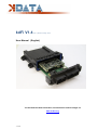
1
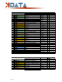
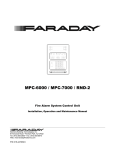
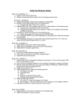
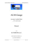
kdFi V1.4
R10
(As from 24 July, 2013)
User Manual (English)
You will find the latest information, documentation and CD images on
www.k-data.org
1 of 12
Index
1. INTRODUCTION
2. INCLUDED IN DELIVERY
3. SOFTWARE
3.1 USB DRIVER
3.2 TUNERSTUDIO
4. CONNECTION
4.1 CABLE TYPES
4.2 FUSES
4.3 USB PORT
4.4 ASSIGNMENT OF THE ADDITIONAL TERMINALS
5. COMMISSIONING
5.1 LED
5.2 SPEED MEASUREMENT
5.3 SENSORS
5.4 THROTTLE POTENTIOMETER
5.5 DIGITAL INPUT
5.6 TABLE SWITCH
5.7 BAROMETRIC CORRECTION
5.8 TACHO OUTPUT
5.9 IDLE SPEED CONTROLLER
5.10 IGNITION
5.11 INJECTION
5.12 RELAIS OUTPUT / BOOST PRESSURE CONTROL
5.13 CAN BUS
6. BASIC PCB
7. WIDEBAND LAMBDA CONTROLLER
8. FIRMWARE UPDATES
9. NOTES
2 of 12
1. Introduction
Congratulation for buying the kdFi V1.4.
The circuit of the kdFi bases on Megasquirt MS2 V3.0. It was refined for the firmware MS2extra and provided with additional
circuits in order to enable easy adaptation to a great number of engine types.
A Wideband Lambda Controller (breitband-lambda.de) is also arranged on the PCB. A Bosch LSU 4.2 Lambda Sonde can be
connected directly without the need to buy a further controller.
In addition for ease of use the serial inputs were replaced by an USB port galvanically isolated from the PC.
2. Included in Delivery
- kdFi V1.4 device ready for use
- Software CD
- PVC housing incl. plug
- User manual
3. Software
It is recommended installing the software from the starting menu of the CD before connecting the kdFi for the first time.
3.1
USB Driver
You will find the USB driver of the FTDI Company on the CD in the directory “USB”. It is the FTDI2232 Chip.
3.2
Tunerstudio
For tuning we recommend using the software “Tunerstudio” available on the Internet under „Tunerstudio.com”. You will find the
corresponding manual on the website of the manufacturer.
4. Connection
The kdFi - like all other voltage supplied parts - must be preceded by a fuse. The amperage rating of the fuse must not
exceed the maximum allowable amperage of the cable.
4.1
Cable Types
Recommended cable types:
Ignition:
min 1.5 mm²
Injection:
min 1.5 mm²
VR sensor:
min 0.5 mm², shielded
Sensors:
min 0.5 mm²
Others:
min 0.75 mm²
3 of 12
4.2
Fuses
We recommend using a 5A fuse for protecting the kdFi V1.4. The kdFi is internally equipped with a 5A slow-blow fuse which
can only be replaced by SMD soldering and doesn’t even protect the Lambda Controller. Therefore avoid tripping this fuse.
4.3
USB Port (Galvanically Isolated)
Since there were occasional disconnects of the USB connection on the previous model kdFi V1.3 due to potential differences
and other electrical disturbances, the USB port of the V1.4 has been galvanically isolated. Another difference is that the part
electrically connected to the PC is "USB powered". This fact simplifies the optimization of the start-up behaviour significantly
because when you restart the ignition, the PC mustn’t download the USB driver each time anew.
The USB chip is of course downwards compatible, which means it can be used both with USB 3.0, 2.0 and 1.1. Each standard
USB cable can be used as connection cable.
4.4
Assignment
The programmable inputs/ outputs of the kdFi are already connected with the corresponding extension circuitry on the PCB.
Connections:
Pin Function
1
A1
2
B1
3
C1
4
D1
5
A2
6
B2
7
C2
8
D2
9
IGN_GND
10 INJ1
11 INJ3
12 INJ2
4 of 12
E/A
IGN
IGN
IGN
IGN
IGN
IGN
IGN
IGN
IGN
INJ
INJ
INJ
Function
Ignition output cylinder 1
Ignition output cylinder 2
Ignition output cylinder 3
Ignition output cylinder 4
Ignition output parallel to cylinder 1
Ignition output parallel to cylinder 2
Ignition output parallel to cylinder 3
Ignition output parallel to cylinder 4
Ground ignition – please ground separately
Injection valve 1
Injection valve 3
Injection valve 2
13
14
15
16
17
18
19
20
21
22
23
24
25
26
27
28
29
30
31
32
33
34
35
36
37
38
39
40
41
42
43
44
45
46
47
48
12V
GND
FP
INJ4
FDLC
FDLO
CAM
JS11
IAC1
OXY2
JS7
GND
GND
GND_RPM
GND_OXY
IAC2
AIR
CLT
RPM
OXY
JS5
LSU_SW
LSU_GE
LSU_RT
LSU_GR
LSU_WS
LSU GN
F2
E2
F1
E1
GND
TPS
TPS_5V
TBL
JS2
E
GND
A
INJ
A
A
E
A
A
E
E
GND
GND
GND
GND
A
E
E
E
E
E
WB
WB
WB
WB
WB
WB
IGN
IGN
IGN
IGN
TPS
TPS
TPS
E
A
Input voltage 12V
Ground
Fuel pump
Injection valve 4
Idle speed controller 3-pin - CLOSED
Idle speed controller 3-pin - OPEN
Rotation speed measurement camshaft
Connector internal SV1-9
Tacho Output (signal for rev counter)
Lambda sensor signal bank 2
Digital Input
Ground
Ground
Ground speed sensor (VR sensor connected to Minus or GND)
Ground lambda sensor signal
Relay Output (max 2A)
Air temperature sensor
Water temperature sensor
Rotation speed measurement crankshaft
Lambda sensor signal
Connector internal SV1-8
Bosch LSU 4.2 : BLACK
Bosch LSU 4.2 : YELLOW
Bosch LSU 4.2 : RED
Bosch LSU 4.2 : GREY
Bosch LSU 4.2 : WHITE
Bosch LSU 4.2 : GREEN
Ignition output parallel to cylinder 6
Ignition output parallel to cylinder 5
Ignition output cylinder 6
Ignition output cylinder 5
Throttle potentiometer Ground
Throttle potentiometer Position Signal
Throttle potentiometer 5V Power Supply
Table Switch
Connector internal SV1-10
The blue coloured entries have been changed compared to the previous version V1.3!
5 of 12
5. Commissioning
5.1
Light Emitting Diodes
Description
Colour
Function
LD1
red
Connection error
LD2
green
Power supply OK
LD3
yellow
Data packet from USB to MS2
LD4
green
Data packet from MS2 to USB
LD5
yellow
Ignition pulse A
LD6
yellow
Ignition pulse B
LD7
yellow
Ignition pulse C
LD8
yellow
Ignition pulse D
LD9
yellow
Ignition pulse E
LD10
yellow
Ignition pulse F
LD11
red
Wideband controller error
LD12
green
Wideband controller LED on: Stand-by
LD12
green
Wideband controller LED flashing slowly: operation
LD12
Green
Wideband controller LED flashing fast: Heat sensor
The LEDs LD5 to LD10 may also have other functions according to the software. They depend on the
customer’s settings.
5.2
Speed Measurement
1. VR Sensor
The measurement via VR sensor is the most widespread way in Europe for car engines. An AC voltage is induced in the coil
of the VR sensor by a metal wheel with 60-2 or 36-1 cogs. A specialised component performing an auto-adaptation to the
different sensors is integrated in the kdFi V1.4. In this way the potentiometers don’t need to be adjusted any more.
2. HALL sensor
With different Hall sensors you possibly need a resistor of 1 to 10 ohm between signal and +5.
5.3
Sensors
The factory settings of kdFi are adapted to Bosch sensors. A separate software calibration of the sensors is possible via
software.
6 of 12
5.4
Throttle Potentiometer
The throttle potentiometer is connected up by a 3-wire cable. +5V and GND are connected to the outer static pins of the
potentiometer. The voltage relating to the throttle position is tapped via the sliding contact and connected to the input TPS
(Throttle Position Sensor).
The covered distance of the potentiometer may be longer than the rotation of the throttle axle. The corresponding calibration is
done via “Tools” – “Calibrate TPS”.
5.5
Digital Input
There is a digital input that can be used for example as “Launch Control”. The corresponding function has to be defined in
Megatune. Specify JS7 as input.
5.6
Table Switch
Via the input "TBL", a second set of parameters can be activated in the controller. With a switch setting the input to ground,
you can switch between two stored ignition and injection maps. This is useful for various tunings such as road/ racing, petrol/
gas, petrol/ E85 etc.
Connecting to a higher voltage than 5V will damage the processor of the kdFi. Digital inputs must only be connected to
ground.
5.7
Barometric Correction
For using the constant barometric correction there must be a second absolute pressure transmitter (MPX4250) at the back
side that is not installed ex works.
The option “Barometric Correction” has to be activated in Megatune “Basic Settings” – “General Lags” and adjusted in
“Extended” – “Barometric Correction”.
Choose JS4 as input.
The sensor can be mounted directly on the solder pads of the PCB next to the MAP sensor.
5.8
Tacho Output
The output “Tacho Output” is provided for standard tachometers. It can be activated in the software “Extended” – “Tacho
Output”. Choose “IAC1“ as “Output on”.
5.9
Idle Speed Controller
The kdFi V1.4 supports both the 2-pin and the 3-pin idle speed controller. Pin connections of the idle speed control:
2-pin: +12V and FDLO
3-pin: +12V and FDLO (open) and FDLC (closed)
7 of 12
5.10 Ignition
The ignition coil can be activated directly by the power drivers integrated in the kdFi V1.4. We recommend using a shielded
multi-conductor cable for connection. The kdFi is equipped with 12 power drivers enabling direct activation of 12 ignition coils
according to the wasted spark principle.
Alternatively to up to 6 ignition coils can be activated according to the Coil on Plug principle.
5.11 Injection
There are 8 outputs (INJ1-8) for injection valves; the first four outputs can be controlled individually. Outputs 5-8 are controlled
in parallel to the first four, and in the version with housing, they are not routed to the external pins. The additional ground
connection (INJ_GND) should be connected to ground with low impedance (high conductor cross-section) to prevent potential
shifts on the PCB. The injection valves are supplied with +12 V via the ignition and the ground wires of the valves are
activated via the control unit
Attention:
The setting whether the injection valves are of high or of low resistance has to be entered in “Basic
Settings” – “Injector Characteristics” strictly before the first test run because false settings can cause
destruction of the injection valves or of the kdFi!
Starting values (no guarantee):
High impedance: PWM Current Limit (%): 100
PWM Time Threshold (ms): 25.5
Low impedance: PWM Current Limit (%): 30
PWM Time Threshold (ms): 1.5
5.12 Relais Output/ Boost Pressure Control
A relay output is available under IAC2, which can switch 2 ampere, but is also suitable for a PWM signal, e.g. boost pressure
control.
5.13 CAN Bus
Like for the Megasquirt 2 the CAN Bus is equipped concerning the hardware, but has to be programmed accordingly by the
user if desired. For further information on this item please read the respective Megasquirt /MSextra websites on the internet.
8 of 12
6. Basic PCB
Dimensions:
Assignment:
9 of 12
Pinout:
Con
Pin Signalname
SV1
SV1
SV1
SV1
SV1
SV1
SV1
SV1
SV1
SV1
SV1
SV1
SV1
SV1
SV1
SV1
SV1
SV1
SV1
SV1
SV1
SV1
SV1
SV1
SV1
SV1
SV1
SV1
SV1
SV1
SV1
SV1
SV1
SV1
SV1
SV1
SV1
SV1
SV1
SV1
1 GND
2 GND
3 V_IN
4 V_IN
5 V_REF
6 7 +5V
8 +12V_E
9 LSU_DIAHD
10 LSU_DIAHD
11 +12V_LSU
12 +12V_LSU
13 LSU_UN
14 LSU_VM
15 LSU_IP
16 LSU_IA
17 UA
18 GP1
19 GP2
20 GP3
21 CJ125_RXD
22 CJ125_TXD
23 GND
24 OXY-1_OUT
25 OXY-1
26 OXY-2
27 BARO
28 MAP
29 TPS
30 AIR
31 CLT
32 RESET
33 BKGD
34 IAC1
35 IDLO
36 IDLC
37 RESERVE_1
38 RESERVE_2
39 FP
40 IAC2
Con
Pin Signalname
SV2
SV2
SV2
SV2
SV2
SV2
SV2
SV2
SV2
SV2
1 TBL
2 JS7
3 RPM-2
4 RPM-2_OUT
5 VR-2-N
6 VR-2-P
7 RPM-1
8 RPM-1_OUT
9 VR-1-N
10 VR-1-P
10 of 12
Description
Typ Application
Power In (Ground)
Power In (Ground)
Power In (12V)
Power In (12V)
REF Out
Not Connected
+5V Out for sensors and circuits
+12V Out sensors and circuits
Lambda-Sensor Heat PWM
Lambda-Sensor Heat PWM
Lambda-Sensor Heat +12V
Lambda-Sensor Heat +12V
Lambda-Sensor Signal UN
Lambda-Sensor Signal VM
Lambda-Sensor Signal IP
Lambda-Sensor Signal IA
Lambda Amplifier Out
I/O-Port ATmega8
Start Lambdacontroler
I/O-Port ATmega8
RS232-Interface to CJ125
RS232-Interface to CJ125
Ground for Pin 24
Wideband Sensor Output
Analogsignal OXY 1
Analogsignal OXY 2
Analogsignal BARO
Analogsignal MAP
Analogsignal TPS
Analogsignal AIR
Analogsignal CLT
Signal Reset Low-Active
Signal Background Interface Pin
Signal IAC1 (e.g. RPM in Instr. cluster)
Idle Valve Open
Idle Valve Close
Reserve 1
Reserve 2
Fuel Pump
Signal IAC2
Main GND
Main GND
12V Igniotion on
12V Igniotion on
Description
Signal TBL
Signal JS7
Signal RPM-Sensor 2
RPM-Sensor_2 Output
Cam Signal Negative
Cam Signal Positive
Signal RPM-Sensor 1
RPM-Sensor_1 Output
Crank Signal Negative
Crank Signal Positive
I/O Type
I
I
I
I
nc
O
O
LSU 4.2 grau
LSU 4.2 grau
LSU 4.2 weiß
LSU 4.2 weiß
LSU 4.2 schwarz
LSU 4.2 gelb
LSU 4.2 rot
nc
nc
I TTL
I TTL
I TTL
TTL
TTL
GND
SV1-25
Lambdasensor 1
Lambdasensor 2
Barometric Sensor
Map Sensor
Throttle Position
Airtemp Sensor
Coolant Sensor
O
I
I
I
I
I
I
I
nc
nc
O
O
O
nc
nc
O
O
0-5V
0-5V
0-5V
0-5V
0-5V
0-5V
Resistor
Resistor
switched GND
switched GND
switched GND
Typ Application
I/O Type
SV2-4
SV2-3
GND
Hall Sensor
SV2-8
SV2-7
VR / Hall Sensor
VR / Hall Sensor
I TTL
I TTL
I
O
I
I
I
O
I
I
Con
Pin Signalname
SV3
SV3
SV3
SV3
SV3
SV3
SV3
SV3
SV3
SV3
SV3
SV3
SV3
SV3
SV3
SV3
SV3
SV3
SV3
SV3
SV3
SV3
SV3
SV3
SV3
SV3
SV3
SV3
SV3
SV3
SV3
SV3
SV3
SV3
SV3
SV3
SV3
SV3
SV3
SV3
1 IGN-A1
2 FB_A1
3 IGN-B1
4 FB_B1
5 IGN-C1
6 FB_C1
7 IGN-D1
8 FB_D1
9 RSP1
10 RSN1
11 IGN-E1
12 FB_E1
13 IGN-F1
14 FB_F1
15 IGN-A2
16 FB_A2
17 IGN-B2
18 FB_B2
19 RSP1/2
20 RSN1/2
21 IGN-C2
22 FB_C2
23 IGN-D2
24 FB_D2
25 IGN-E2
26 FB_E2
27 IGN-F2
28 FB_F2
29 RSP2
30 RSN2
31 MCU_PA.6
32 MCU_PA.7
33 INJ-1
34 INJ-2
35 INJ-3
36 INJ-4
37 INJ-5
38 INJ-6
39 INJ-7
40 INJ-8
Con
Pin Signalname
SV4
SV4
SV4
SV4
SV4
SV4
SV4
SV4
SV4
SV4
1 MCU_RXD
2 MCU_TXD
3 CAN_H
4 CAN_L
5 USB_RXD
6 USB_TXD
7 VBUS_USB
8 GND_USB
9 DP_USB
10 DM_USB
11 of 12
Description
Typ Application
Ignition_A1
Feedback_A1
Ignition_B1
Feedback_B1
Ignition_C1
Feedback_C1
Ignition_D1
Feedback_D1
Current Resistor Sense Positive
Current Resistor Sense Negative
Ignition_E1
Feedback_E1
Ignition_F1
Feedback_F1
Ignition_A2
Feedback_A2
Ignition_B2
Feedback_B2
Current Resistor Sense Positive
Current Resistor Sense Negative
Ignition_C2
Feedback_C2
Ignition_D2
Feedback_D2
Ignition_E2
Feedback_E2
Ignition_F2
Feedback_F2
Current Resistor Sense Positive
Current Resistor Sense Negative
Signal MCU_PA.6
Signal MCU_PA.7
Injector_1
Injector_2
Injector_3
Injector_4
Injector_5
Injector_6
Injector_7
Injector_8
Gate IGBT
Collector IGBT
Gate IGBT
Collector IGBT
Gate IGBT
Collector IGBT
Gate IGBT
Collector IGBT
GND
GND
Gate IGBT
Collector IGBT
Gate IGBT
Collector IGBT
Gate IGBT
Collector IGBT
Gate IGBT
Collector IGBT
GND
GND
Gate IGBT
Collector IGBT
Gate IGBT
Collector IGBT
Gate IGBT
Collector IGBT
Gate IGBT
Collector IGBT
GND
GND
Description
Typ Application
RS232-Interface to MC9S12C64
RS232-Interface to MC9S12C64
CAN-BUS-Interface to MC9S12C64
CAN-BUS-Interface to MC9S12C64
RS232-Interface to FT232R (Optocoubler)
RS232-Interface to FT232R (Optocoubler)
USB-Interface
USB-Interface
USB-Interface
USB-Interface
SV4-6
SV4-5
nc
nc
SV4-2
SV4-1
USB red
USB black
USB green
USB white
Ground Injector
Ground Injector
Ground Injector
Ground Injector
Ground Injector
Ground Injector
Ground Injector
Ground Injector
I/O Type
O
I
O
I
O
I
O
I
O
I
O
I
O
I
O
I
O
I
O
I
O
I
O
I
nc
nc
O
O
O
O
O
O
O
O
I/O Type
Con
Pin Signalname
SV5
SV5
SV5
SV5
SV5
SV5
SV5
SV5
SV5
SV5
SV5
SV5
SV5
SV5
SV5
SV5
SV5
SV5
SV5
SV5
SV5
SV5
SV5
SV5
SV5
SV5
SV5
SV5
SV5
SV5
SV5
SV5
SV5
SV5
SV5
SV5
SV5
SV5
SV5
SV5
1 GND
2 +5V
3 EC_SCK
4 EC_SI
5 EC_SO
6 CS_EC1
7 MAXI_EC1
8 NOMI_EC1
9 SPKD_EC1
10 CS_EC2
11 MAXI_EC2
12 NOMI_EC2
13 SPKD_EC2
14 CS_EC3
15 MAXI_EC3
16 NOMI_EC3
17 SPKD_EC3
18 MCU_PA.3
19 MCU_PA.4
20 MCU_PA.5
21 MCU_PB.4
22 MCU_PB.5
23 MCU_PB.6
24 MCU_PB.7
25 MCU_PE.2
26 MCU_PE.3
27 MCU_PE.5
28 MCU_PE.6
29 MCU_PJ.6
30 MCU_PJ.7
31 MCU_PP.0
32 MCU_PP.1
33 MCU_PP.2
34 MCU_PP.3
35 MCU_PP.4
36 MCU_PP.5
37 MCU_PP.6
38 MCU_PP.7
39 MCU_PS.2
40 MCU_PS.3
Description
Power
Power
SPI Bus
SPI Bus
SPI Bus
SPI Bus Engine Controller 1
SPI Bus Engine Controller 1
SPI Bus Engine Controller 1
SPI Bus Engine Controller 1
SPI Bus Engine Controller 2
SPI Bus Engine Controller 2
SPI Bus Engine Controller 2
SPI Bus Engine Controller 2
SPI Bus Engine Controller 3
SPI Bus Engine Controller 3
SPI Bus Engine Controller 3
SPI Bus Engine Controller 3
Signal MCU_PA.3
Signal MCU_PA.4
Signal MCU_PA.5
Signal MCU_PB.4
Signal MCU_PB.5
Signal MCU_PB.6
Signal MCU_PB.7
Signal MCU_PE.2
Signal MCU_PE.3
Signal MCU_PE.5
Signal MCU_PE.6
Signal MCU_PJ.6
Signal MCU_PJ.7
Signal MCU_PP.0
Signal MCU_PP.1
Signal MCU_PP.2
Signal MCU_PP.3
Signal MCU_PP.4
Signal MCU_PP.5
Signal MCU_PP.6
Signal MCU_PP.7
Signal MCU_PS.2
Signal MCU_PS.3
Typ Application
I/O Type
nc
nc
nc
nc
nc
nc
nc
nc
nc
nc
nc
nc
nc
nc
nc
nc
nc
nc
nc
nc
nc
nc
nc
nc
nc
nc
nc
nc
nc
nc
nc
nc
nc
nc
nc
nc
nc
nc
nc
nc
7. Wideband Lambda Controller
(www.breitbandlambda.de)
The integrated lambda controller is activated by switching the input "GP2" to ground. This can be done continuously with a
bridge as the kdFi is only energized as long as the ignition is turned on. The measurement signal is output to OXY_out in form
of a 0-5V signal and corresponds to the PLX signal 0-5V = AFR10-AFR20.
This characteristic is stored in Tunerstudio and has already been loaded during the test of the control device. After a firmware
update this characteristic but must be selected again.
8. Firmware Updates
Firmware updates are always performed at your own risk. It may happen that the existing firmware is deleted by
disconnections or incompatible computers/ software and it can only be reloaded via a BDM interface. We offer this
service, but it is not covered by warranty!
Tunerstudio must be closed during the firmware update to prevent access conflicts. The ignition coils must be disconnected
during the firmware update, until the appropriate configuration has been reloaded via MSQ file.
12 of 12