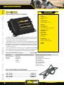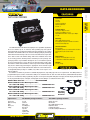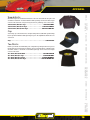
1
HISTORY
Racepak Data Systems was founded in 1984 to design and build affordable
and reliable onboard data acquisition equipment. As Racepak built and refined
its early data acquisition systems, the equipment found its way into many
forms of motorsports before finally catching the attention of the drag racing
community. Though there had been previous attempts to construct data
recorders for Top Fuel and Funny Cars, none had proven reliable. Racepak
knew that if they could develop onboard data acquisition that could survive
in this hostile environment, that it would survive anywhere. By achieving this
goal, the Racepak data recorder was established as the clear choice in data
acquisition. The result is that Racepak can now be found on nearly every
professional drag racing vehicle competing throughout the world.
Racepak has reinvested heavily into supporting the quest for information
technology. The Racepak line has now grown to include a large selection
of unique loggers, software, gauges, and ancillary equipment, for use in a
variety of motorsports. This has positioned the company as a leader in the
data acquisition industry, and expanded our clientele to include industrial
applications, OE manufacturers, and testing facilities, as well as a broad
spectrum of land, water, and snow-based motorsports. In 2005, Racepak
was acquired by MSD Performance Group. Known as the leader in highperformance ignition and electronic products, MSD Ignition offered the perfect
environment for Racepak’s continued growth.
The team at Racepak Data Systems is proud of our accomplishments and the
reputation we have developed in the motorsports community. We firmly believe
that reputation is the key to our success. Racepak continues to follow the
same guiding principles that have led us to the forefront of the data acquisition
industry. Our unwavering goal remains to produce reliable, efficient, state of the
art data recorders. It is key that they remain at a price accessible to professionals
and sportsmen alike and that we support our customers with whatever service
they may need. Our push for continual product advancement, dissatisfaction
with status quo, and the burning desire to achieve the impossible; have made
us a perfect match for the customers we serve.
Finally, we wish to thank our customers who have played an integral role
in the growth of Racepak. It is through your faith in us, and the input and
ongoing support of our products, that we have become the leader in data
acquisition. We value that relationship and look forward to further cultivating
it as we continue to grow.
Racepak systems are designed to take the intimidation factor out of
purchasing a data acquisition system. Further, we are always available to
answer any questions or provide component selection advice. You can contact
a Racepak Customer Service representative at 949-709-5556 or check out
www.racepak.com.
2
WWW.RACEPAK.COM
CONTENTS
DRAG
CLOSED
COURSE
PULLING
STREET MOUNTING
Introduction . . . . . . . . . . . . . . . . . . . . . . . . . . . . . . . . . . . . . . . . . 2-3
Application Chart. . . . . . . . . . . . . . . . . . . . . . . . . . . . . . . . . . . . . . . 4
Drag . . . . . . . . . . . . . . . . . . . . . . . . . . . . . . . . . . . . . . . . . . . . . . 5-34
Closed Course. . . . . . . . . . . . . . . . . . . . . . . . . . . . . . . . . . . . . 35-58
Pulling. . . . . . . . . . . . . . . . . . . . . . . . . . . . . . . . . . . . . . . . . . . . . . . 59
Street. . . . . . . . . . . . . . . . . . . . . . . . . . . . . . . . . . . . . . . . . . . . . 60-64
Mounting. . . . . . . . . . . . . . . . . . . . . . . . . . . . . . . . . . . . . . . . . . 65-66
Download Hardware. . . . . . . . . . . . . . . . . . . . . . . . . . . . . . . . . . . 67
Video. . . . . . . . . . . . . . . . . . . . . . . . . . . . . . . . . . . . . . . . . . . . . 68-69
Software. . . . . . . . . . . . . . . . . . . . . . . . . . . . . . . . . . . . . . . . . . 70-72
Weather Stations. . . . . . . . . . . . . . . . . . . . . . . . . . . . . . . . . . . 73-74
Apparel. . . . . . . . . . . . . . . . . . . . . . . . . . . . . . . . . . . . . . . . . . . . . . 75
Adding Sensors to a GPS Logger . . . . . . . . . . . . . . . . . . . . . . . . 76
Example Schematics. . . . . . . . . . . . . . . . . . . . . . . . . . . . . . . . . . . 77
Glossary. . . . . . . . . . . . . . . . . . . . . . . . . . . . . . . . . . . . . . . . . . 78-79
Payment
All orders are credit card or wire transfer. All international orders are wire transfer. Credit Cards:
are the preferred method of payment. Racepak accepts Visa,MasterCard and Amex. When paying
by credit card be sure to include card number, expiration date, and name of card holder. Checks:
If prepaying by check please allow ten days for the check to clear your bank. Bank Drafts: If
paying by bank draft allow three days for transmission of the draft to our account. International accounts allow five days. Also please remember to include sufficient funds to cover the amount
deducted by the bank for transfer fees.
Racepak’s primary method of shipping is via Fed Ex. This includes all forms of Fed Ex delivery
options for domestic and international services. Please specify which method you prefer at the time
of your order. If a method is not specified Racepak will use the least expensive option available.
Requesting a shipping carrier other than Fed Ex will incur additional charges. All shipping charges
are the responsibility of the customer and will be added to the invoice.
Warranty
DOWNLOAD
HARDWARE
Shipping
VIDEO
Racepak/CSI Data Systems makes every effort to insure that our products and services are of
the highest quality and standards. It is our intention to maintain a mutually beneficial and cordial
relationship with each and every one of our customers.
Racepak/CSI warrants all merchandise manufactured by Racepak against defects in workmanship
or materials for a period of six months after the date of purchase. This warranty applies to the first
retail purchaser and covers only those products exposed to normal use or service. It does not apply
to those products used for a purpose for which it was not designed, or which has been altered in any
way that would be detrimental to the performance or life of the product, or misapplication, misuse,
negligence, or accident. Any part or product found to be defective after examination by Racepak will
be repaired or replaced. Racepak assumes no responsibility for diagnosis, removal and/or installation
labor, loss of vehicle use, loss of time, inconvenience or any other consequential expenses.
This warranty is in lieu of any other expressed or implied warranties, including any implied warranty
of merchantability or fitness, and any other obligation on the part of Racepak, or selling dealer.
SOFTWARE
WEATHER
STATIONS
(949) 709-5555
3
WEATHER
STATIONS
SOFTWARE
VIDEO
DOWNLOAD
HARDWARE
MOUNTING STREET
PULLING
CLOSED
COURSE
DRAG
APPLICATION CHART
4
WWW.RACEPAK.COM
VEHICLE WIRING
DRAG
Racepak Smartwire
FEATURES
POWER CONTROL MODULE
CLOSED
COURSE
Capacity:
125 total amps
Channels:
30 total channel outputs =
8 channels @ 20 amp maximum
22 channels @ 10 amp maximum
PULLING
12 hardwired switch inputs
Data Output:
Volts
Amps
State
STREET MOUNTING
Response:
3.0 millisecond
Programming:
USB Interface
SOFTWARE
SmartWire
Switch Panel
500-KT-SW30
500-SW-PNL8
500-SW-5MI6
500-MB-SPxxxx (Available sizes are: 1.50”, 1.625” and 1.75”)
580-CA-BN5P-xxx (Variety of sizes offered)
280-CA-BN5P-xxx (Available sizes are: 9”, 18” and 36”)
WEATHER
STATIONS
(949) 709-5555
Includes:
Racepak SmartWire Module
Connector Kit
VIDEO
SmartWire Module Kit . . . . . . . . . . . . . . . . . . . . . . . . . . . . . . .
SmartWire Switch Panel. . . . . . . . . . . . . . . . . . . . . . . . . . . . . .
SmartWire Switch Module. . . . . . . . . . . . . . . . . . . . . . . . . . . .
Switch Panel Mount Brackets. . . . . . . . . . . . . . . . . . . . . . . . .
SmartWire to Switch Panel Cable. . . . . . . . . . . . . . . . . . . . . .
SmartWire to V-Net Cable . . . . . . . . . . . . . . . . . . . . . . . . . . . .
Dimensions:
6” (L) X 5.5” (W) X 1.5” (H)
(25.2 cm X 13.9 cm X 3.8 cm)
DOWNLOAD
HARDWARE
Solving the wiring complexity of the modern race car, the Racepak SmartWire
is a fully programmable power control module. While traditional wiring provides
control of vehicle electronic components through the routing of wiring to single
or multiple fuses, relay and circuit breaker panels, the Racepak Smartwire
functions as a central “command center” for all vehicle wiring.
Based on Racepak’s exclusive single cable V-Net technology, the Racepak
SmartWire module is the electronic “starting point”, with a direct main power
connection from the vehicle battery to the module. Each input/output is then
user defined, both in function, power requirements and current exceeding limits
via a USB connection to the user’s PC. The design of the module functions
to both reduce overall installation weight / clutter, while providing a quicker
reacting electronic system, through the solid state switching design.
Manual activation is achieved through use of an optional eight switch
Racepak Switch Panel. From the Racepak Smartwire module, a single small
cable is routed to the SwitchPanel, reducing wiring clutter. Users needing
additional switch panel capabilities can easily expand through the use of a
“jumper” cable to a second Racepak SwitchPanel.
The V-Net compatibility insures a seamless integration with existing
Racepak data logger or displayed equipped vehicles, while also providing a
future upgrade path for additional inputs, control modules and instrumentation,
when utilized as a standalone power control module.
Each Racepak SmartWire Kit includes the module and connector kit.
5
DATA RECORDERS
DRAG
V300SD
FEATURES
DATA RECORDER
CLOSED
COURSE
Channels:
67 total
V-Net: 56
Analog: 4 hard-wired
Digital: 4 hard-wired
Internal: 3
MOUNTING STREET
PULLING
Sample Rates:
V-Net: up to 100 per second
Analog: up to 1000 per second
Digital: RPM and switch contacts up to 100 per
second
SOFTWARE
VIDEO
DOWNLOAD
HARDWARE
The V300SD series data recorder is our most popular data recorder. In
base configuration, the V300SD monitors five parameters, but it can be
expanded to monitor up to 67 channels of data to meet the needs of most
users. The V300SD can sample data as quickly as 1000 times per second.
Uploading recorded data to your computer is done via a SD memory card,
which provides you with hours of recording time and the ability to store
many runs prior to uploading the data. This means that no download cable
is required! The V300SD also has multiple methods of displaying monitored
data in real time. When linked by serial cable to your PC you can view all
recorded functions in either graph format or on 8 virtual gauges while the
vehicle is running. Any monitored function can also be displayed in real
time on Racepak’s optional Intelli-Gauges, UDX dash or IQ3 display dash.
Also, the V300SD can monitor overall ignition timing with the optional timing
package. See page 24 for more information.
WEATHER
STATIONS
Internal Sensors:
Battery Voltage
Longitudinal g-meter (acceleration and
deceleration)
Lateral g-meter (side-to-side motion)
Dimensions:
4.374” (L) X 3.935” (W) X 1.230” (H)
(11.11cm X 9.994cm X 3.12cm)
Weight:
10 ounces (.28 kg)
Typical Uses:
The V300SD package monitors:
The V300 package includes:
Pro-Mod
Pro Stock
Top Dragster
Top Sportsman
Comp Eliminator
Super Comp
Super Gas
Motorcycles
Land speed cars
Drag Boats
Engine RPM
Driveline RPM
Engine v. Driveline RPM differential
Battery voltage
Acceleration g-force
Lateral g-force
V300SD Data Recorder
SD memory card
Driveshaft or rear wheel RPM sensor with split collar and magnet kit
Datalink software kit with serial programming cable
V-Net tee connector with terminator caps
Power/Ground/Engine RPM/Driveshaft Harness
(clutch RPM optional upgrade)
V300/V300SD Recorder Mounting Brackets,
for 1.250” O.D. tubing . . . . . . . . . . . . . . . . . . . . .
V300/V300SD Recorder Mounting Brackets,
for 1.500” O.D. tubing . . . . . . . . . . . . . . . . . . . . .
V300/V300SD Recorder Mounting Brackets,
for 1.625” O.D. tubing . . . . . . . . . . . . . . . . . . . . .
V300/V300SD Recorder Mounting Brackets,
for 1.750” O.D. tubing . . . . . . . . . . . . . . . . . . . . .
6
Memory:
SD memory card
Recording time depends on number of
channels monitored and sample rates
Record multiple runs
Cabless
800-MB-V300-125
800-MB-V300-150
800-MB-V300-162
800-MB-V300-175
Recorder Mounting Brackets
WWW.RACEPAK.COM
DATA RECORDERS
DRAG
V500
FEATURES
DATA RECORDER
PULLING
Sample Rates:
V-Net: up to 100 per second
Analog: up to 1000 per second
Digital: RPM and switch contacts up to 100 per
second
Digital: Timing intervals within 1/1000 of a
second
CLOSED
COURSE
Channels:
75 total
V-Net: 56
Analog: 8 hard-wired
Digital: 8 hard-wired
Internal: 3
Internal Sensors:
Battery Voltage
Longitudinal g-meter (acceleration and
deceleration)
Lateral g-meter (side-to-side motion)
Dimensions:
5.350” (L) X 5.550” (W) X 1.215” (H)
(13.598cm X 14.09cm X 3.08cm)
Weight:
17 ounces (48 kg)
V500 with data cartridge download and Datalink Standard. . 200-KT-V500-4MDC
The V500 package includes:
Pro Mod
Pro Stock
Drag Boats
Dynamometers
Industrial equipment
Engine RPM
Driveline RPM
Engine v. Driveline RPM differential
Battery voltage
Acceleration g-force
Lateral g-force
V500 Data Recorder
Driveshaft or rear wheel RPM sensor with split collar and magnet kit
Datalink software kit with serial programming/download cable
V-Net tee connector with terminator caps
(clutch RPM optional)
Power/Ground/Engine RPM/Driveshaft Harness (clutch RPM optional upgrade)
(949) 709-5555
800-MB-V500-125
800-MB-V500-150
800-MB-V500-162
800-MB-V500-175
Recorder Mounting Brackets
WEATHER
STATIONS
G2X Pro/V500 Recorder Mounting Brackets,
for 1.250” O.D. tubing . . . . . . . . . . . . . . . . . . . . .
G2X Pro/V500 Recorder Mounting Brackets,
for 1.500” O.D. tubing . . . . . . . . . . . . . . . . . . . . .
G2X Pro/V500 Recorder Mounting Brackets,
for 1.625” O.D. tubing . . . . . . . . . . . . . . . . . . . . .
G2X Pro/V500 Recorder Mounting Brackets,
for 1.750” O.D. tubing . . . . . . . . . . . . . . . . . . . . .
SOFTWARE
The V500 package monitors:
VIDEO
Typical Uses:
DOWNLOAD
HARDWARE
If you need to monitor many channels of information while using fast
sampling rates for extended recording periods, the V500 is for you. The
V500 handles more channels of information than the V300SD data recorder,
supporting up to 75 total channels of information. With that comes high
sampling speed rates (up to 1000/sec.) and an internal recording capacity
of 4 MB of memory. Information can be displayed in real time on a PC
monitor, uploaded to the PC for analysis using the Racepak Datalink Data
Analysis software, or displayed on the optional Intelli-Gauges, UDX dash or
IQ3 display dash. The V500 can be equipped to monitor overall timing, or
individual cylinder timing on those vehicles using the proper programmable
ignition system, with optional timing package.
STREET MOUNTING
Memory:
4 MB
Recording time depends on number of channels
monitored and sample rates
7
DATA RECORDERS
DRAG
Sportsman
FEATURES
DRAG RACE DATA LOGGER
CLOSED
COURSE
Channels:
21 total
8 EGT (V-Net)
7 internal & external
6 V-Net
PULLING
Sample Rates:
V-Net: up to 100 per second
MOUNTING STREET
Memory:
SD memory card
Up to 8MB SD card
Record multiple runs before download
DOWNLOAD
HARDWARE
Containing the same hardware and software utilized by our professional
series data recorders, the Sportsman Drag Race Data Logger package offers
an economical solution for the sportsman drag racer.
Utilizing Racepak’s exclusive V-Net sensor input compatibility with our full
V-Net product line, while the 21 total sensor inputs (internal and external) provide
the ideal balance of cost and features, allowing the sportsman racer to monitor
information such as EGT, oil pressure, water temperature, transmission pressure,
12 volt event, air fuel etc.
The use of a SD memory card ensures hours of recording time and the ability
to store multiple run files, before downloading. Installation is simplified by the
use of a factory terminated wiring harness and pre-progammed software.
Internal Sensors:
Engine RPM
Driveshaft RPM
Battery Voltage
Start Record button
2 axis G meter
12 Volt event
Dimensions:
6” (L) X 4.5” (W) X 1” (H)
(15.2cm X 11.43cm X 2.54cm)
Weight:
0.65 lbs.
SOFTWARE
VIDEO
Sportsman with Datalink Lite Software . . . . . . . . . . . . . 610-KT-SPRTMN
Typical Uses:
The Sportsman base package monitors:
The Sportsman package includes:
Non-blown Sportsman
Super Comp
Super Gas
Engine RPM
Driveline RPM
Battery Voltage
Accel G
Lateral G
12 Volt Event
Sportsman data logger
User terminated harness
Driveshaft collar, sensor & mount bracket
Start record button
SD to USB card reader
USB to serial port adapter
Serial programming cable
DatalinkII software
Installation / user manual
Sportsman Mounting Bracket
Includes logger mounting plate, black anodized billet aluminum clamp bracket
WEATHER
STATIONS
1.250” dia tube . . . . . . . . . . . . . . . . . . . . . . . . . . . . . . . . . . . 610-MB-125
1.500” dia tube . . . . . . . . . . . . . . . . . . . . . . . . . . . . . . . . . . . 610-MB-150
1.625” dia tube . . . . . . . . . . . . . . . . . . . . . . . . . . . . . . . . . 610-MB-1625
1.750” dia tube . . . . . . . . . . . . . . . . . . . . . . . . . . . . . . . . . . . 610-MB-175
8
WWW.RACEPAK.COM
DATA RECORDERS
DRAG
LDX Logger Dash Extreme
DATA RECORDER
CLOSED
COURSE
PULLING
FEATURES
STREET MOUNTING
Channels:
37 total
V-Net: 32 digital/analog
Harness: 5 (engine RPM, driveshaft RPM, water
temperature, oil pressure, volts)
Sample Rates:
V-Net: up to 100 per second
Digital: RPM and switch contacts up to 100 per
second
Memory:
1 MB
Recording time depends on number of channels
monitored and sample rates
VIDEO
Dimensions:
10.200” (L) X 4.000” (W) X .750” (H)
(mounting surface to face, 2.000” OAL depth)
(25.908cm X 10.16cm X 1.905cm)
Screen dimensions 7.250” X 2.625”
(18.415cm X 6.6675cm)
DOWNLOAD
HARDWARE
The LDX Logger Dash combines a digital display dash with an internal
data recorder, creating a compact, lightweight, all-in-one data acquisition
system. The LDX Logger Dash utilizes the benefits of Racepak’s single cable
V-Net technology by sharing the data from all sensors with the data logger.
In addition to the wiring harness, which imports the signals from the engine
RPM, driveshaft RPM, water temperature, oil pressure and battery voltage,
up to 32 optional sensors may be attached via the single V-Net cable. This
yields a total recording capacity of 37 sensor inputs.
The LDX Logger Dash can record and upload data to a PC via a supplied
serial cable, while at the same time displaying the input from up to 21 of
those sensors on the display screen. With a simple push of a button, users
can view the displayed sensor data by scrolling through four screens of
information. Each page contains five user programmable sensor inputs,
plus the engine RPM bar graph.
Selecting what sensor data will be viewed is accomplished through the
DatalinkII software. Also included are output ports to allow connection to
an external shift light and warning light. Shift points can be programmed
using the left and right buttons located at the bottom of the dash, while
reviewing settings on the display. These same buttons are also utilized
to program warning limits and review minimum and maximum values for
displayed data.
One MB of memory provides a generous amount of recording time, with
sampling rates available up to 100 times per second, per channel. Uploaded
data is accomplished through a supplied 6’ serial cable. Four threaded studs
on the rear of the dash are providing for mounting. This product is typically
utilized for motorsports not requiring any type of lap timing information.
Weight:
25 ounces (71 kg)
SOFTWARE
LDX Logger Dash . . . . . . . . . . . . . . . . . . . . . . . 250-KT-LDX
The LDX package monitors:
The LDX Logger Dash package includes:
Drag Racing
Engine RPM
Driveshaft RPM
Water Temp
Battery Voltage
LDX Logger Dash
Wiring harness
Driveshaft RPM sensor kit
Datalink download software kit with 6-foot cable
V-Net tee connector with terminator caps
Water temperature sensor
Oil pressure sensor
Instruction manual
(949) 709-5555
WEATHER
STATIONS
Typical Uses:
9
Intro to V-Net Dashes and Gauges
When Racepak introduced their series of V-Net
data loggers, which allows all sensors to transmit
their data back to the data logger via a single cable,
the next logical progression in this technology was to
add the ability to plug gauges and dashes into this
same V-Net cable. By doing so, this would allow the
gauge to share the sensor information with the data
logger, thus providing a true “vehicle network” of data
logger, sensors and gauges, all routing their data
through a single cable. This design has proven to be
tremendously popular, as the installation, weight and
complexity of data systems and related components
was greatly simplified.
Taking this design a step further, this line of “IntelliGauges” and LCD Digital Display Dashes could now
use the data transmitted down this single V-Net cable
to activate external warning and shift lights, while being
programmed through this same single V-Net cable.
Now, all programming, warnings, data logging and
data display would be accomplished in a very efficient
manner.
Digital Display Dashes
Racepak offers three series of digital displays, the UDX,
the G2X and the IQ3. Each utilize Racepak’s exclusive
V-Net single cable technology, allowing for an extremely
simple installation, while providing a variety of data for
a multitude of motorsports. More information on each
system follows.
Intelli-Gauges
The Intelli-Gauges are a great support component
of the V-Net data recording systems. Their unique
capabilities and ease of installation make them
attractive for a variety of performance applications. All
of the gauges are 2 5/8” diameter and feature a full 270°
sweep needle, a programmable digital display and
electro-luminescent lighting. See page 16 for additional
information concerning the Intelli-Gauges.
WEATHER
STATIONS
SOFTWARE
VIDEO
DOWNLOAD
HARDWARE
MOUNTING STREET
PULLING
CLOSED
COURSE
DRAG
INSTRUMENTATION
10
WWW.RACEPAK.COM
INSTRUMENTATION
FEATURES
Includes:
UDX Display Dash
CLOSED
COURSE
Specifications:
Display up to 21 sensor inputs via 4 pages.
Adjustable backlighting
User defined warning lights
Minimum/Maximum recall
PULLING
The UDX is a digital display dash, capable of being utilized with any of Racepak’s V-Net series of data recorders.
With connection to the data logger via the same V-Net cable utilized by the
external sensors, the UDX display is capable of “sharing” sensor data with the
data logger, thus providing the ability to display or trigger warnings based on
any internal or external sensor in use by the data logger.
DRAG
UDX Display Dash
Display Dash Provides:
Any 21 sensor inputs
Shift Light Output
Warning Lights
IQ3 Display Dash
Weight:
21 ozs. (.58 kg)
STREET MOUNTING
UDX Display. . . . . . . . . . . . . . . . . . . . . . . . . . . . . . . 250-DS-UDX
Dimensions:
4” (H) X 10.2” (W) X .75”(deep*)
* Requires 2” rear clearance
(10.16cm X 25.90cm X 1.90cm)
UDX Display
FEATURES
Dimensions:
7.25” (L) X 4.000” (W) X 1.125” (deep)
(18.41cm X 10.16cm X 5.39cm)
Weight:
1 lb. (453g)
SOFTWARE
IQ3 External Programming Buttons
VIDEO
IQ3 Display Dash. . . . . . . . . . . . . . . . . . . . . . . . . . . . . 250-DS-IQ3
DOWNLOAD
HARDWARE
The IQ3 Display Dash can be utilized with any of Racepak’s V-Net data loggers,
providing a compact, fully programmable LCD digital dash for use in a variety
of motorsports.
A single V-Net cable is routed to the rear of the dash, providing power and
access to all sensor information transmitted to the data logger. Up to 24 different
sensor inputs may be displayed on a total of four programmable pages. The blue
backlight provides excellent viewing for both daylight and nighttime usage, while
the low luster display screen provides excellent protection against scratches.
Progressive shift lights, eight warning lights and all inputs are easily
programmable through the DatalinkII software supplied with each data logger.
In addition, the IQ3 dash can be utilized as a standalone display dash,
independent of a Racepak V-Net data logger, through the use of optional sensors
off of the V-Net port, located on the rear of the dash.
Specifications:
Display up to 28 inputs via 4 pages
Blue backlight
Gear Indicator
Eight user defined alarms with on screen warning
text and lights
User defined 5 character sensor input names
User defined shift light output
Shielded, low luster display for sunlight viewing
Metric and English capable
IQ3 Display
Remote mount programming buttons for IQ3 dash. Includes two buttons, wiring and connectors
Programming buttons . . . . . . . . . . . . . . . . . 280-SW-IQ3BTN
Trim to fit, vacuum formed plastic mounting panel.
Faux Carbon . . . . . . . . . . . . . . . . . . . . . . . . . . . . . . . . . 800-MB-IQ3-PCF
Black . . . . . . . . . . . . . . . . . . . . . . . . . . . . . . . . . . . . . . 800-MB-IQ3-PBLK
Silver . . . . . . . . . . . . . . . . . . . . . . . . . . . . . . . . . . . . . . . . 800-MB-IQ3-PAL
(949) 709-5555
WEATHER
STATIONS
IQ3 Mounting Panels
11
UDX Replay Dash
MOUNTING STREET
PULLING
CLOSED
COURSE
DRAG
INSTRUMENTATION
Given the popularity of replay and recall gauges, the UDX Replay Dash
goes one step further by providing the ability to replay up to 10 minutes of
data, while also functioning as full feature LCD display dash.
The UDX Replay Dash includes a wire loom and sensors for engine RPM,
water temperature, oil pressure and battery voltage. Sensors for displaying
other sensor inputs must be purchased separately.
Replay Model (Display & Replay). . . . . . . . . . . . 250-KT-UDXRP
Specifications:
Display up to 21 sensor inputs via 4 pages.
Adjustable backlighting
User defined warning lights
Minimum/Maximum recall
DOWNLOAD
HARDWARE
Includes:
UDX Replay Dash
Water temperature sensor
Oil pressure sensor
Wire loom and connectors for sensor input
termination
UDX Mounting Panels
Trim to fit, vacuum formed plastic mounting panel.
Faux Carbon . . . . . . . . . . . . . . . . . . . . . . . . . . . . . . . . 800-MB-UDX-PCF
Black . . . . . . . . . . . . . . . . . . . . . . . . . . . . . . . . . . . . . 800-MB-UDX-PBLK
Silver . . . . . . . . . . . . . . . . . . . . . . . . . . . . . . . . . . . . . . . 800-MB-UDX-PAL
SOFTWARE
VIDEO
FEATURES
Display Dash Provides View of:
Any 21 sensor inputs connected to the dash
Shift Light Output
Warning Lights
Dimensions:
4” (H) X 10.2” (W) X .75”(deep*)
* Requires 2” rear clearance
(10.16cm X 25.908cm X 1.905cm)
WEATHER
STATIONS
Weight:
21 ozs. (.58 kg)
12
WWW.RACEPAK.COM
INSTRUMENTATION
DRAG
Intelli-Gauges
INTELLI-GAUGE DIMENSIONS
1.330
.372”
1.480
2.000
2.000
2.870
FEATURES
SOFTWARE
User Programmable warning levels
Download recorded data to PC
Plug-and-play installation
Analog and digital display
Lightweight, sonic welded
Electro-luminescent radial lighting
ELIMINATE THE CLUTTER: Using the Intelli-Gauge
with one of our data acquisition systems is a great
way to eliminate some of the wiring clutter under the
hood. These gauge derive their signal from the data
acquisition system’s sensors, so there is no duplication
of wiring or sensors as you would have with other
stand-alone gauges.
VIDEO
REAR
SIDE
ENGINEERED FOR LOOKS AND PERFORMANCE:
When you combine the looks and performance of
these gauges you have an unbeatable combination
of elegance and function. Intelli-Gauge cases and
connectors are sonic welded to provide maximum
protection against contaminating elements. They weigh
a mere 49 grams. Their smart looks can be attributed
to an easy-to-read dial face that uses wide spread
increment marks in the prime operating range, a digital
display to complement the needle movement, and a
smooth curved bezel that surrounds your choice of a
white of black dial face.
DOWNLOAD
HARDWARE
2.310
2.600
EASY INSTALLATION: If a function is currently being
monitored on the V-Net, simply plug the gauge online
and it shares the signals from that function’s sensor.
If not, install a sensor and its module for the function
you wish to monitor, plug both modules onto the V-Net
cable, and the installation is complete.
STREET MOUNTING
All of the gauges are 2 5/8” diameter and feature a 270° sweep needle
along with a programmable digital display. The gauges are available
with a black or white face and are easy to view thanks to electroluminescent lighting. Page 17 shows all of the available gauges.
WARNING ALARM: Intelli-Gauges can act as a
watchdog. Each gauge can monitor user-programmable
minimum or maximum limits and flash the digital
display (and/or a remote light) when either threshold
is exceeded.
PULLING
Racepak’s Intelli-Gauges are the best way to relay pertinent engine and
drivetrain information when using our V-Net data recording systems.
The V-Net wiring capabilities means the gauges and the data acquisition
components can share the same sensors to reduce wiring.
CLOSED
COURSE
INTELLIGENT GAUGES: These are not your average
analog or digital gauge. They are both. In addition, they
are highly accurate, stylish, dependable, and provide
real time display for your monitored functions.
WEATHER
STATIONS
(949) 709-5555
13
DRAG
INSTRUMENTATION
INTELLI-GAUGE SELECTION CHART
RPM, TACHOMETER
1,000-10,500 RPM
250-IG-100BB
250-IG-100WB
RPM, TURBINE PERCENTAGE, N1
RPM, TURBINE PERCENTAGE, N2
TEMPERATURE, WATER (Street)
TEMPERATURE, WATER (Race)
TEMPERATURE, OIL
TEMPERATURE, EXHAUST GAS
TEMPERATURE, EXHAUST GAS #2
TEMPERATURE, EXHAUST GAS
TEMPERATURE, CYLINDER HEAD
TEMPERATURE, TRANSMISSION
PRESSURE, OIL
PRESSURE, OIL
PRESSURE, FUEL
PRESSURE, FUEL
PRESSURE, FUEL
PRESSURE, FUEL
PRESSURE, BRAKE
PRESSURE, NITROUS
PRESSURE, Generic
PRESSURE, Generic
PRESSURE, Generic
PRESSURE, Generic
BOOST / VACUUM
BOOST
VACUUM
AIR/FUEL RATIO
FLOW
FUEL LEVEL
VOLTS
VOLTS (with internal sensor)
0-120%
0-120%
100°-280°F
60°-200°F
140°-280°F
600°-1,600°F
600°-1,600°F
0-1000°C
100°-600°F
50°-350°F
0-100 psi
0-250 psi
0-15 psi
0-100 psi
0-250 psi
0-500 psi
0-1,500 psi
0-1,600 psi
0-200 psi
0-300 psi
0-500 psi
0-1,000 psi
30 psi-0-30 In. hg
0-60 psi
0-30 In. hg
10-18
3.5-4.5 GPM
E-F
8-20
8-20
NA
NA
250-IG-110BB
250-IG-120BB
250-IG-130BB
250-IG-140BB
250-IG-145BB
NA
250-IG-150BB
250-IG-135BB
250-IG-160BB
NA
250-IG-170BB
250-IG-165BB
NA
NA
250-IG-180BB
250-IG-175BB
250-IG-190BB
250-IG-193BB
NA
250-IG-197BB
250-IG-215BB
NA
250-IG-210BB
NA
NA
NA
250-IG-200BB
250-IG-204BB
250-IG-218 WB
250-IG-219WB
250-IG-110WB
250-IG-120WB
250-IG-130WB
250-IG-140WB
250-IG-145WB
250-IG-220WB
250-IG-150WB
250-IG-135WB
250-IG-160WB
250-IG-162WB
250-IG-170WB
250-IG-165WB
250-IG-167WB
250-IG-226WB
250-IG-180WB
250-IG-175WB
250-IG-190WB
250-IG-193WB
250-IG-223WB
250-IG-197WB
250-IG-215WB
250-IG-217WB
250-IG-210WB
250-IG-224WB
250-IG-222WB
250-IG-225WB
250-IG-200WB
250-IG-204WB
20-32
NA
250-IG-221WB
VOLTS
After the first gauge each subsequent gauge is connected with a gauge to gauge jumper cable.
The first Intelli-Gauge connects to the
V-Net cable using a Gauge Tee Cable.
SOFTWARE
VIDEO
DOWNLOAD
HARDWARE
MOUNTING STREET
PULLING
CLOSED
COURSE
(Gauge includes connector cable. Sensor and modules available on page 24-30)
INTELLI-GAUGES
RANGE
BLACK FACE
WHITE FACE
Gauge Cables
Gauge to Gauge Jumper Cables
WEATHER
STATIONS
Used to connect each gauge in series after the first gauge.
Each end of the cable has the small round connector that plugs
directly into the back of the Intelli-Gauges.
Gauge Tee Cables
Connects first gauge to V-Net cable or another V-Net module.
14
Length
PN#
8”
280-CA-RGG-008
16”
280-CA-RGG-016
24”
280-CA-RGG-024
48”
280-CA-RGG-048
288”
280-CA-RGG-288
8”
280-CA-RGG-T008
16”
280-CA-RGG-T016
24”
280-CA-RGG-T024
WWW.RACEPAK.COM
V-NET TECHNOLOGY
DRAG
CLOSED
COURSE
PULLING
Racepak’s Vehicle Network (V-Net) is a “smart data” transfer network providing the ability to transmit multiple signals from each
sensor over a single cable. This technology creates a system in which the individual components interact with each other; making a
simpler, more compact system which can be expanded with ease.
The key to accomplishing this is in the modular connectors that attach each of the devices to the main V-Net cable. Each module
is essentially a miniature computer, which houses circuit boards and a microprocessor that identifies and retrieves only the proper
incoming signals and allows other signals to pass through.
Whether you will be installing a single gauge set up, or a full-blown data acquisition system, all components are attached to the
system using the modular snap-together connectors. Adding components onto the system is simple. Just find a junction in the main
V-Net cable, separate the connectors, and sandwich the new sensor’s module between them. Then command your software to read
the new configuration. It will
automatically recognize any
V300SD DATA RECORDER
DIGITAL ANALOG V-NET
contains three internal sensors:
PORT
PORT
PORT
additions or deletions from the
Longitudinal G-meter (Accelerometer)
Lateral G-meter (side to side), Battery Voltage
system.
V Series Recorders
Gauge integration is
Terminator Cap
another strength of the V-Net
+
+
+
+
system, but don’t mistake the
Racepak gauges for garden
V-Net
Four Available High Speed Analog Channels.
Tee Connector
These channels are usually reserved for monitoring functions
variety gauges. If your vehicle
that require sample rates faster than 100 samples per second.
is equipped with a V-Net
DIGITAL (RPM)
recording system, the gauges
WIRING HARNESS
BLUE (START RECORDING BUTTON)
simply use the sensors and
RED (12V POWER SWITCH)
BLACK (ENGINE RPM)
wiring that are already in place
YELLOW (CLUTCH RPM, IF USED)
GRAY (DRIVESHAFT RPM)
to provide full time display of
the data being monitored.
The same holds true for
Racepak’s digital display
V-Net Cables
dashes. Some models of Terminator
Cap
the dash will rely solely upon
the data recorder’s sensors
to provide the information
they display, while others
are stand-alone requiring
Fuel
Oil
Pressure
no data recorder. When
Pressure
Module & Sensor
Module & Sensor
you add Datalink II, the best
Tachometer
Oil Pressure
4 EGT
Gauge & Module Gauge & Module
4 EGT
Windows®-based software in
Probes
Probes
Intelli-Gauges
& Box
EGT
& Box
the business, you will see why
Ultra Dashes
Thermocouples
Racepak continues to be the
& Module
most popular and widely used
V-Net Modules
data acquisition system in the
industry.
+
STREET MOUNTING
DOWNLOAD
HARDWARE
VIDEO
SOFTWARE
+
+
+
In order for a function to be monitored on the V-Net, the signal from that function must pass through two components: a sensor and
a module. The sensor is the unit that actually measures the input from the function (i.e. pressure, temperature, etc.), while the module
converts the signal so it can be transmitted over the V-Net. To make it easy for you to select the proper components, Racepak offers
a variety of manners, as shown below. In the module sensor section that follows, you will find a complete listing of these components
divided into the following categories:
with sensor (pre-programmed)
without sensor (pre-programmed)
with sensor (not pre-programmed)
(949) 709-5555
Digital V-Net Modules:
with sensor (pre-programmed)
without sensor (pre-programmed)
no sensor required (pre-programmed)
WEATHER
STATIONS
Analog V-Net Modules:
15
Analog V-Net Modules with Sensors (pre-programmed)
These pre-programmed analog function module and sensor combinations are ready for plug-and-play installation on the
V-Net cable.
PRESSURE
(Note: All pressure and vacuum modules have a 48” pigtail cable between the V-Net module and the sensor.)
Boost (Manifold) 0-75 psi . . . . . . . . . . . . . . . . . . . . . 220-VP-PT-BST75
Brakes, 0-1500 psi . . . . . . . . . . . . . . . . . . . . . . . . . . 220-VP-PT-B1500
Fuel, Carburetor, 0-15 psi . . . . . . . . . . . . . . . . . . . . . . 220-VP-PT-CP15
Fuel, Nozzle, 0-150 psi . . . . . . . . . . . . . . . . . . . . . . 220-VP-PT-NP150
Fuel, Nozzle, 0-300 psi . . . . . . . . . . . . . . . . . . . . . . . 220-VP-PT-NP300
Fuel, Nozzle, 0-500 psi . . . . . . . . . . . . . . . . . . . . . . 220-VP-PT-NP500
Fuel, Pump, 0-75 psi . . . . . . . . . . . . . . . . . . . . . . . . . 220-VP-PT-PP075
Fuel, Pump, 0-150 psi . . . . . . . . . . . . . . . . . . . . . . . . 220-VP-PT-PP150
Fuel, Pump, 0-300 psi . . . . . . . . . . . . . . . . . . . . . . . . 220-VP-PT-PP300
Fuel, Pump, 0-500 psi . . . . . . . . . . . . . . . . . . . . . . . . 220-VP-PT-PP500
Nitrous Bottle #1, 0-1500 psi . . . . . . . . . . . . . . . . . . . . . 220-VP-PT-N1
Nitrous Bottle #2, 0-1500 psi . . . . . . . . . . . . . . . . . . . . . 220-VP-PT-N2
Nitrous Fuel #1, 0-15 psi . . . . . . . . . . . . . . . . . . . . . 220-VP-PT-NF115
Nitrous Fuel #2, 0-15 psi . . . . . . . . . . . . . . . . . . . . . 220-VP-PT-NF215
Nitrous Fuel #3, 0-15 psi. . . . . . . . . . . . . . . . . . . . . . 220-VP-PT-NF315
Nitrous Fuel #4, 0-15 psi. . . . . . . . . . . . . . . . . . . . . . 220-VP-PT-NF415
Oil, 0-150 psi . . . . . . . . . . . . . . . . . . . . . . . . . . . . . . . 220-VP-PT-OP150
Oil, 0-300 psi . . . . . . . . . . . . . . . . . . . . . . . . . . . . . . 220-VP-PT-OP300
Pressure Differential, 0-40” H²O to 15 psi . . . . . . 220-VP-PT-PD145
Transmission, 0-300 psi . . . . . . . . . . . . . . . . . . . . . . 220-VP-PT-TP300
Turbo Back Pressure #1, 0-75 psi . . . . . . . . . . . . . . 220-VP-PT-EP175
Fuel Pressure 0-75 psi
Turbo Back Pressure #2, 0-75 psi . . . . . . . . . . . . . . 220-VP-PT-EP275
Turbocharger Outlet #1, 0-75 psi . . . . . . . . . . . . . . 220-VP-PT-TB1O
Wheelie Bar, Left, 0-3000 psi . . . . . . . . . . . . . . . . . 220-VP-PT-WBL3K
Wheelie Bar, Right, 0-3000 psi . . . . . . . . . . . . . . . . 220-VP-PT-WBR3K
VACUUM
Manifold, 30 psi-0-30 In. hg . . . . . . . . . . . . . . . . . . . 220-VP-PT-BVAC
Pan (Crankcase), 0-30 In. hg . . . . . . . . . . . . . . . . . . 220-VP-PT-PVAC
TEMPERATURE
(Note: pigtail cable lengths are shown in parenthesis.)
Cylinder Head, Left, 0-600°F, (36”). . . . . . . . . . . . . . 220-VP-TC-HEADL
Cylinder Head, Right, 0-600°F, (36”) . . . . . . . . . . . . 220-VP-TC-HEADR
Engine Oil, 0-300°F, (48”) . . . . . . . . . . . . . . . . . . . . . . . 220-VP-TR-OIL
Intake Manifold, Open Tip, 0-600°F, (36”). . . . . . . . 220-VP-TC-MANIF
Intercooler Inlet, 0-300°F, (72”) . . . . . . . . . . . . . . . . . . 220-VP-TR-ICTI
Rear End Oil, 0-300°F, (72”) . . . . . . . . . . . . . . . . . . . . . 220-VP-TR-RET
Transmission Oil, 0-300°F, (72”). . . . . . . . . . . . . . . . 220-VP-TR-TRANS
Water, 0-300°F, (72”). . . . . . . . . . . . . . . . . . . . . . . . 220-VP-TR-WATER
WEATHER
STATIONS
SOFTWARE
VIDEO
DOWNLOAD
HARDWARE
MOUNTING STREET
PULLING
CLOSED
COURSE
DRAG
V-NET SENSORS AND MODULES
Fluid Temp 0°-300°F
16
WWW.RACEPAK.COM
V-NET SENSORS AND MODULES
DRAG
TEMPERATURE, continued
EGT Junction
STREET MOUNTING
EGT Cylinder 1
DOWNLOAD
HARDWARE
Analog V-Net Modules without Sensors
(pre-programmed)
VIDEO
SOFTWARE
These analog function modules have been programmed for general usage,
and have not been assigned to a specific task. Use of these modules on the V-Net
cable requires the addition of a sensor and configuration of the module using your
DatalinkII software.
Voltage, 0-5 Volt Input, 5 Volt Output . . . . . . . . . . . . . 230-VM-AN-5V
Voltage, 0-5 Volt Input, 12 Volt Output. . . . . . . . . . . . 230-VM-AN-12V
Pressure, 5 Volt (see sensors page 25) . . . . . . . . . . . 230-VM-PT-5V
Position/Movement, Rotary or Linear . . . . . . . . . . . . . . 230-VM-TPS
Temperature, Fluid-type, 0-300°F . . . . . . . . . . . . . . . . 230-VM-TR-300
For use with Racepak sensor #810-TR-300 only, see page 28.
Temperature, Low, 0-600°F . . . . . . . . . . . . . . . . . . . . 230-VM-TC-600
For use with type K thermocouples only, see page 27.
Temperature, High, 0-1800°F . . . . . . . . . . . . . . . . . . 230-VM-TC-1800
For use with type K thermocouples only, see page 27.
Air/Fuel Sensor Input, Single . . . . . . . . . . . . . . . . . . . . . . . 230-VM-AF
Air/Fuel Sensor Input, 4 Station . . . . . . . . . . . . 230-VM-AF (cyl #s)
Battery Voltage . . . . . . . . . . . . . . . . . . . . . . . . . . . . . . 230-VM-BVOLT
Voltage Differential . . . . . . . . . . . . . . . . . . . . . . . . . 230-VM-5VDIFF
PULLING
Exhaust Gas Temperatures/Single Cylinder:
(Single cylinder modules include the thermocouple.)
EGT, Cylinder #1 . . . . . . . . . . . . . . . . . . . . . . . . . . . . 220-VP-TC-EGT1
EGT, Cylinder #2 . . . . . . . . . . . . . . . . . . . . . . . . . . . . 220-VP-TC-EGT2
EGT, Cylinder #3 . . . . . . . . . . . . . . . . . . . . . . . . . . . . 220-VP-TC-EGT3
EGT, Cylinder #4 . . . . . . . . . . . . . . . . . . . . . . . . . . . . 220-VP-TC-EGT4
EGT, Cylinder #5 . . . . . . . . . . . . . . . . . . . . . . . . . . . . 220-VP-TC-EGT5
EGT, Cylinder #6 . . . . . . . . . . . . . . . . . . . . . . . . . . . . 220-VP-TC-EGT6
EGT, Cylinder #7 . . . . . . . . . . . . . . . . . . . . . . . . . . . . 220-VP-TC-EGT7
EGT, Cylinder #8 . . . . . . . . . . . . . . . . . . . . . . . . . . . . 220-VP-TC-EGT8
Thermocouple Only, .187” Diameter: specify 18” or 27” length
Thermocouple Only, .250” Diameter: specify 9”, 18”, 28” or 36” length
CLOSED
COURSE
Exhaust Gas Temperatures/Cylinder Bank Sets
EGT, Junction Box & 4 Probes, 1357, Small Block . . 220-VP-TC-1357S
EGT, Junction Box & 4 Probes, 2468, Small Block . . 220-VP-TC-2468S
EGT, Junction Box & 4 Probes, 1357, Big Block . . . . 220-VP-TC-1357B
EGT, Junction Box & 4 Probes, 2468, Big Block . . . 220-VP-TC-2468B
EGT, Junction Box & 4 Probes, 1234. . . . . . . . . . . . . . 220-VP-TC-1234
EGT, Junction Box & 4 Probes, 5678 . . . . . . . . . . . . . 220-VP-TC-5678
EGT, Junction Box & 4 Probes, Motorcycle . . . . . . . 220-VP-TC-1234M
EGT, Junction Box & 3 Probes, 123 . . . . . . . . . . . . . . . 220-VP-TC-123
EGT, Junction Box & 3 Probes, 456 . . . . . . . . . . . . . . . 220-VP-TC-456
EGT, Junction Box & 3 Probes, 135 . . . . . . . . . . . . . . . 220-VP-TC-135
EGT, Junction Box & 3 Probes, 246 . . . . . . . . . . . . . . 220-VP-TC-246
The EGT junction box sets are ordered by the cylinder bank sequence they serve.
Voltage 0-5 Input
WEATHER
STATIONS
(949) 709-5555
17
Analog V-Net Modules with Sensors (NOT pre-programmed)
The module/sensor combinations are the same as the V-Net Modules with Sensors/Analog on pages 19-20 with the exception that
they have not been pre-programmed. Each of the pressure or temperature module/sensor combinations below is designed to be
attached to the V-Net cable. Once installed, they must be programmed using the Configuration File in the Datalink software.
PRESSURE
0-15 psi . . . . . . . . . . . . . . . . . . . . . . . . . . . . . . . . . . . . . 220-VS-15GVT
0-75 psi . . . . . . . . . . . . . . . . . . . . . . . . . . . . . . . . . . . . . 220-VS-75GVT
0-150 psi . . . . . . . . . . . . . . . . . . . . . . . . . . . . . . . . . . . 220-VS-150GVT
0-300 psi . . . . . . . . . . . . . . . . . . . . . . . . . . . . . . . . . . . 220-VS-300GVT
0-500 psi . . . . . . . . . . . . . . . . . . . . . . . . . . . . . . . . . . . 220-VS-500GVT
0-1500 psi . . . . . . . . . . . . . . . . . . . . . . . . . . . . . . . . . 220-VS-1500SVT
Vacuum/Pressure, 30 In. hg-0-30 psi . . . . . . . . . . . . . . . . . 220-VS-VB
To measure pressure functions using sensors seen on page 25.
TEMPERATURE
0-75 psi
Fluid Temperature
Temperature, 0-300°F, Fluid-type Sensor . . . . . . . . . . 220-VS-TR-300
Uses the #810-TR-300 sensor seen on page 28.
QUICK DISCONNECT TERMINAL KIT
Thee connector kits provide you with the components that will allow you to
shorten the pigtail cable between the V-Net module and pressure sensor or a TRtype temperature sensors. Each kit includes enough components for one module.
Fluid Temperature Sensors . . . . . . . . . . . . . . . . . . . . . . 810-CN-TR2P
Use with V-Net modules and temperature sensors having prefix number of 220-VPTR-, 220-VM-TR-, or 230-VM-TR-.
Pressure Sensors . . . . . . . . . . . . . . . . . . . . . . . . . . . . . . . 810-CN-TI3P
Use with V-Net module and pressure sensor having prefix number of 220-VP-PT-,
220-VS-, or 230-VM-PT-.
0°-300° F
Temperature
EXTENSION CABLES
These custom-built extensions can be used to extend the length of cables that
use a 2-Pin or 3-Pin Molex connector to attach the sensor to the power harness or a
module’s pigtail. Please specify length required when ordering.
2-Pin Molex Cable, Specify Length . . . . . . . . . . . . . . . 800-CA-EXT2P
3-Pin Molex Cable, Specify Length . . . . . . . . . . . . . . . 800-CA-EXT3P
MOLEX TERMINAL KITS
These connector kits can be used if the need arises to shorten a cable that is
terminate. Available with a two or three pin Molex connector. Kit includes both a male
and female connector and pins.
2-Pin Molex Connector Kit . . . . . . . . . . . . . . . . . . . . . . 810-CN-MOL2
Pin Molex Connector Kit . . . . . . . . . . . . . . . . . . . . . . . 800-CN-MOL3
Crimp Tool (for Molex Terminal Pins) . . . . . . . . . 800-XP-CRIMP-01F
WEATHER
STATIONS
SOFTWARE
VIDEO
DOWNLOAD
HARDWARE
MOUNTING STREET
PULLING
CLOSED
COURSE
DRAG
V-NET SENSORS AND MODULES
3-Pin Molex
Connector
2-Pin Molex
Connector
18
WWW.RACEPAK.COM
V-NET SENSORS AND MODULES
DRAG
Digital V-Net Modules with Sensors (Pre-Programmed)
These pre-programmed digital function modules and sensor combinations are ready for plug-and-play installation on the V-Net
cable. See sensors only page.
CLOSED
COURSE
PULLING
Driveshaft RPM
STREET MOUNTING
Clutch RPM . . . . . . . . . . . . . . . . . . . . . . . . . . . . . . . . . . . . 220-VP-CL-1
Monitors magnetic pulses using a Zero Crossing sensor.
Drive Shaft RPM, Automotive
(Contact Closure Sensor) . . . . . . . . . . . . . . . . . . . . . . . 220-VP-DS-2
Contact Closure sensor, includes split collar, magnet, and bracket kit.
Drive Shaft/Rear Wheel RPM, Motorcycle . . . . . . . . . 220-VP-ZXDS-2
Monitors magnetic pulses using a Zero Crossing sensor.
Front Wheel RPM . . . . . . . . . . . . . . . . . . . . . . . . . . . . . . 220-VP-FWZX
Monitors magnetic pulses using a Zero Crossing sensor.
Front Wheel RPM . . . . . . . . . . . . . . . . . . . . . . . . . . . . 220-VP-FWHE3
Monitors ferrous metal pulses using a Hall Effect sensor.
Turbo Speed . . . . . . . . . . . . . . . . . . . . . . . . . . . . 220-VP-TURBORPM
for use with Racepak V-Net Data Loggers
Turbo Speed V-Net Module only . . . . . . . . . . . . . . . . 230-VM-TURBO
Turbo Speed Sensor only . . . . . . . . . . . . . . . . . . . . . . 800-SS-SPEED
Digital V-Net Modules without Sensors (Pre-Programmed)
Digital V-Net Modules, No Sensor Required (Pre-programmed)
DOWNLOAD
HARDWARE
These pre-programmed digital function modules are ready for plug-and-play installation on the V-Net cable. You must add the
appropriate sensor to the module.
Zero Crossing Input (see page 26) . . . . . . . . . . . . . . . . 230-VM-ZX-1
Hall Effect Input (see page 26) . . . . . . . . . . . . . . . . . 230-VM-RPMHE
Contact Closure Input (see page 26) . . . . . . . . . . . . . . 230-VM-CC-1
Event Marker Input, 12 Volt . . . . . . . . . . . . . . . . . . . . 230-VM-EVENT
Event Marker Input, Switch Closure . . . . . . . . . . . 230-VM-EVENTSW
Flow Meter (see page 25) . . . . . . . . . . . . . . . . . . . . . . 230-VM-FLOW
Four Channel Digital Input . . . . . . . . . . . . . . . . . . . . . 230-VM-4DIGIN
Zero Crossing Input
Four Channel Digital Output . . . . . . . . . . . . . . . . . 230-VM-4DIGOUT
VIDEO
These modules do not require a sensor. They use the pulse from the component they are monitoring as the signal to the module. Each
has been programmed for the specific use noted and is ready for plug-and-play installation on the V-Net cable.
ENGINE RPM
SOFTWARE
(Programmable to read from multiple cylinders applications):
Engine RPM Input Module . . . . . . . . . . . . . . . . . . . . . 220-VP-TACH-4
EVENT INPUTS
Engine RPM Input
(949) 709-5555
WEATHER
STATIONS
Transbrake Event (12 volt Triggered)
(monitors transbrake solenoid) . . . . . . . . . . . . . . 220-VP-TBRAKE
Wide Open Throttle Event (On/Off Switched Input)
(See switch page 28) . . . . . . . . . . . . . . . . . . . . 220-VP-WOTEVENT
Clutch Event (12 volt Triggered)
(Monitors two step clutch pedal switch) . . . . 220-VP-CLTEVENT
19
CLOSED
COURSE
DRAG
V-NET SENSORS AND MODULES
EFI Data Interface
These V-Net modules have been created to interface with many electronic fuel injection systems on the market. Each V-Net
EFI Data Interface module is equipped to allow direct connection with EFI. These modules allow your V-series data recorder to
share the data collected by these systems rather than having to install duplicate sensors to monitor functions that are already
being monitored by the EFI system. The shared data can be recorded or displayed just as you would any function monitored
independently by your Racepak V-series recorder. Caution should be exercised to ensure that you do not exceed the maximum
number of V-Net channels supported by your particular logger. The individual functions monitored by each EFI system are
outlined in the chart below.
EFI Type
Accel DFI Gen VII
AEM
Autronic SMC & SM2
Autronic SM4 V107 & V109
Big Stuff 3
Corvette C6 OBDII GMX3 (2006 and later)
EFI Technologies
FAST XFI CAN
FAST Serial
Generic J1939 CAN
Haltech
Holley EFI (Commander)
Hondata KPro
Megasquirt I
Megasquirt II
MEFI 4B J1939 (GM PN 12584052 or 12575479)
Motec M400, M600, M800, M84
Motec M4, M48 Omex
Omniteck EC44
PRO EFI
Vipec
WOLF V500
EFI V-Net Module Part Number
230-VM-EFIDFI
230-VM-EFIAEM
230-VM-EFIAUT
230-VM-EFIAUT4
230-VM-EFIBS3
230-VM-EFIC6
230-VM-EFITECH
230-VM-EFIXFI
230-VM-EFIFST
230-VM-EFICAN
230-VM-EFIHAL
230-VM-EFIHOL
230-VM-EFIHOND
230-VM-EFIMSI
230-VM-EFIMS2
230-VM-EFIM4
230-VM-EFIMOTEC
230-VM-EFIMOTSR
230-VM-EFIOMEX
230-VM-EFIEC44
230-VM-EFIPRO
230-VM-EFIVIPEC 230-VM-EFIWOLF
WEATHER
STATIONS
SOFTWARE
VIDEO
DOWNLOAD
HARDWARE
MOUNTING STREET
PULLING
For use with Racepak V-Net data loggers.
20
WWW.RACEPAK.COM
V-NET SENSORS AND MODULES
DRAG
Shift Light/Event Module
CLOSED
COURSE
The Shift Light Module allows you to use any LED-style light (300 milliamp maximum)
as a fully-programmable, stand-alone shift light. By accessing the engine RPM off of
the V-Net you can program up to six separate shift alarm signals. Each shift point is
user-programmable using the DatalinkII software. Shift light module does not include
the shift light. See Shift Light on page 36. This module will also show you when the shift
light was triggered to come on.
Shift Light Module (Light not included) . . . . . . . . . 230-VM-SHIFTLT
PULLING
Tach Converter
The output signal that is used to trigger magnetos is different than a conventional
electronic ignition. This compact device converts the Pro Mag’s coil signal into a 12
volt square wave signal so common tachometers designed for electronic ignitions can
be used with the Pro Mag.
Ignition Timing Kit
MSD Pro Mag Tach
Adapter
VIDEO
Ignition Timing Kit
Overall for V500
SOFTWARE
Note the following requirements:
Any V300SD not ordered with this option must be returned to Racepak for upgrade:
• Engine must utilize flying magnet crank trigger wheel
• DatalinkII standard software required
• Contact Racepak for complete details
Ignition Timing Kit, Overall, V300SD. . . . . . . . . . . . . 200-UG-TIMV300S
DOWNLOAD
HARDWARE
By equipping the V500 data recorder with this kit it can track the overall timing, or
if you are using a battery ignition system that provides adjustable individual cylinder
timing, you can monitor the timing on each cylinder as well. These kits provide the
components to compare the crankshaft’s position to the firing pulse(s) of the ignition. Magneto equipped engines, or battery ignition engines without individual cylinder timing
capabilities, would use the overall timing kit.
Ignition Timing Kit, Overall, V500 Only . . . . . . . . . 800-KT-TIMINGOV
Ignition Timing Kit, Individual, V500 Only . . . . . . . . 800-KT-TIMING
V300SD customers can monitor overall ignition timing utilizing Racepak’s V300SD
Timing Kit. Use of this package requires removal of the start logging button, which is
replaced by a crankshaft rpm sensor. Start logging is then initiated by another channel
(engine rpm, etc) or by use of a V-Net event module which then allows use of the start
logging button.
STREET MOUNTING
MSD Pro Mag Tach Converter. . . . . . . . . . . . . . . . 810-SN-MAG-CONV
MSD Magneto Pickup Adapter
(MSD 12 or 20 amp mag) 800-CA-MAGADPT
Cable provides easy connection for RPM sensor between magneto and coil.
Shift Light Module
WEATHER
STATIONS
(949) 709-5555
21
WEATHER
STATIONS
SOFTWARE
VIDEO
DOWNLOAD
HARDWARE
MOUNTING STREET
PULLING
CLOSED
COURSE
DRAG
V-NET SENSORS AND MODULES
Air/Fuel Sensors
Racepak has created a selection of A/F controllers and sensors created specifically for tuning race engines. Each of these 2 and 4
channel controllers are designed to be connected to the V-Net cable of Racepak V-series recorders. When ordering please be aware that
the sensors are calibrated for use on specific ports of the controller and cannot be interchanged from port to port without recalibration.
All sensors have a 13” pigtail cable, and the controller has a 37” cable for attachment to the sensor. These lengths cannot be altered.
Controllers are ordered by cylinder bank layout.
Racepak A/F sensors are compatible with either gasoline or methanol fueled engines. Gasoline application will display A/F ratios between
9.55:1 and 20:1, while methanol is shown from 4.22:1 to 8.7:1. Please specify the type of fuel you will be using when ordering. Each sensor
includes one weldment and plug.
AIR/FUEL CONTROLLERS (SENSORS MUST BE ORDERED SEPARATELY)
2 Channel Controller . . . . . . . . . . . . . . . . . . . . . . . . . . . . 220-VM-AF2
For use with 2 A/F sensors.
4 Channel Controller, Cylinders 1, 3, 5, 7 . . . . . . . 220-VM-AF4-1357
For use on 1, 3, 5, 7 cylinder bank of V8, i.e. GM & Mopar.
4 Channel Controller, Cylinders 2, 4, 6, 8 . . . . . . . 220-VM-AF4-2468
For use on 2, 4, 6, 8 cylinder bank of V8, i.e. GM & Mopar.
4 Channel Controller, Cylinders 1, 2, 3, 4 . . . . . . . 220-VM-AF$-1234
For use on 1, 2, 3, 4 cylinder bank of V8, i.e. Ford.
4 Channel Controller, Cylinders 5, 6, 7, 8 . . . . . . . 220-VM-AF4-5678
For use on 5, 6, 7, 8 cylinder bank of V8, i.e. Ford.
Air/Fuel Sensor Only . . . . . . . . . . . . . . . . . . . . . . . . . . 810-SN-AFAMP
Air/Fuel Weldment & Plug . . . . . . . . . . . . . . . . . . . . 810-TX-AFWLDP
Weldments are included with purchase of controller.
Air/Fuel Harness ‘A’ Side . . . . . . . . . . . . . . . . . . . . . . . . 280-CA-LSUA
Air/Fuel Harness ‘B’ Side . . . . . . . . . . . . . . . . . . . . . . . 280-CA-LSUB
2 Channel Air/Fuel
Controller
Single Air/Fuel Controller with Sensor
Single channel air/fuel sensor package. Includes controller, (1) Bosch LSU air/fuel
sensor, weld bung, wiring harness, instructions. Includes 0-5V reference output for
external devices. For use with Racepak V-Net data loggers
AF1 Package. . . . . . . . . . . . . . . . . . . . . . . . . . . . . . . . . . . . . . . . . . 220-VM-AF1
Relay Control Module
A Relay Control Module is the device which permits the V-Net system to perform
a host of automated tasks. It allows any information transmitted over the V-Net to be
used to activate external high power devices such as a switch, solenoid, water pump,
fan, or lights. Each module has two programmable output relays.
Each relay can have up to two separate (analog and/or digital) control signals that
must be met before the relay is engaged. For example, one relay can be programmed
to turn on a water pump only when a ‘Pump’ switch is on and the water temperature
is above the programmed value, while the other relay can be used to activate an
ignition kill switch only if the engine RPM is above a programmed value and the oil
pressure is lower than a predetermined pressure. Relays are included.
Relay Control Module . . . . . . . . . . . . . . . . . . . . . . . . . 230-VM-RELAY
Relay Control
Module
Steering Sensor
Column mounting steering sensor package includes rotary sensor, column mount,
billet contact wheel and V-Net module.
For use with Racepak V-Net data loggers
Steering Sensor Package. . . . . . . . . . . . . . . . . . . . . . . . . 220-VP-SK-1
22
WWW.RACEPAK.COM
INTERFACE MODULES
Analog Interface Modules without Sensor
Analog
Port
PULLING
RPM
Port
CLOSED
COURSE
Interface modules are another unique component of the V-series recorders. These black 7-pin modules differ from the blue 5-pin
V-Net modules in both the application and the manner in which they perform. They are designed to provide a modular method of
assembly for the sensors that connect to either the hardwired RPM or Analog input ports of V300SD, V500 or G2X Pro data recorders.
Each Interface module provides the necessary signal conditioning for its attached sensor thereby allowing the sensors to communicate
with the Logger via a single cable.
Interface modules do not require any programming, however you may only attach up to four Interface module together in series. The
four modules may be connected directly to each other (Daisy-chained) or they may be linked with an Interface cable as illustrated below.
The list below shows a selection of Interface modules that will help you in the task of connecting almost any type of digital or analog
sensor to a V300SD, V500 or G2X Pro recorder.
DRAG
Interface Modules
V300SD shown
Interface Modules
Dust
Cap
Interface
Cable
Interface
Cable
VIDEO
Tach Input . . . . . . . . . . . . . . . . . . . . . . . . . . . . . . . . . . . . 240-IM-TACH
Zero Crossing Sensor Input . . . . . . . . . . . . . . . . . . . . . . . . 240-IM-ZX
Contact Closure Sensor Input . . . . . . . . . . . . . . . . . . . . . . 240-IM-CC
Contact Closure Sensor, 12v Output . . . . . . . . . . . . . 240-IM-CC-12V
DOWNLOAD
HARDWARE
Pressure Input, 5 Volt . . . . . . . . . . . . . . . . . . . . . . . . . . . 240-IM-PT-5V
Pressure Input, 12 Volt . . . . . . . . . . . . . . . . . . . . . . . . . 240-IM-PT-12V
Temperature, Thermocouple Input, 0-600°F . . . . . . . . 240-IM-TC600
Temperature, Thermocouple Input, 0-1800°F . . . . . . 240-IM-TC1800
Position/Travel Input . . . . . . . . . . . . . . . . . . . . . . . . . . . 240-IM-TRAV
Shock Travel, Right Front, 28” Pigtail (Std.) . . . . 240-IM-TRAV28RF
Shock Travel, Right Front, 38” Pigtail . . . . . . . . . . 240-IM-TRAV38RF
Shock Travel, Left Front, 65” Pigtail (Std.) . . . . . . 240-IM-TRAV65LF
Shock Travel, Right Rear, 48” Pigtail (Std.) . . . . 240-IM-TRAV48RR
Shock Travel, Right Rear, 72” Pigtail . . . . . . . . . 240-IM-TRAV72RR
Shock Travel, Left Rear, 48” Pigtail . . . . . . . . . . . 240-IM-TRAV48LR
Shock Travel, Left Rear, 84” Pigtail (Std.) . . . . . . 240-IM-TRAV84LR
Digital Interface Modules without Sensor
STREET MOUNTING
Switch
Shock Travel
Interface Module
SOFTWARE
Door Car Drag Shock Kit Front
Includes two 0-4” travel linear sensors, two IM modules,
108” IM cable and installation instructions.
Front Kit 280-KT-DSHKTRVF
Includes two 0-8” travel linear sensors, two IM modules, 6”
IM cable and installation instructions.
Rear Kit
280-KT-DSHKTRVR
(949) 709-5555
Front Kit
Rear Kit
WEATHER
STATIONS
Door Car Drag Shock Kit Rear
23
V-Net modules and Interface modules, although similar
7-PIN, BLACK
5-PIN, BLUE
in construction and appearance, are very different in the
CABLE LENGTH
V-NET
INTERFACE
functions they perform. It is important that components
6”
280-CA-VM-006
280-CA-IM-006
designed for one system not be interchanged with
12”
280-CA-VM-012
280-CA-IM-012
18”
280-CA-VM-018
280-CA-IM-018
the other. V-Net cables use a 5-pin connector, while
24”
280-CA-VM-024
280-CA-IM-024
Interface cables use a 7-pin connector. So that cables
36”
280-CA-VM-036
280-CA-IM-036
can be identified at a glance Racepak has color-coded
48”
280-CA-VM-048
280-CA-IM-048
the connectors on the end of the cables. V-Net cable
60”
280-CA-VM-060
280-CA-IM-060
connectors are blue, just like the modules to which they
72”
280-CA-VM-072
280-CA-IM-072
attach, while Interface cable connectors and modules
84”
280-CA-VM-084
280-CA-IM-084
are black.
96”
280-CA-VM-096
280-CA-IM-096
The cables listed may be used to link the components
108”
280-CA-VM-108
280-CA-IM-108
to other listed components of the same system, or to
120”
280-CA-VM-120
280-CA-IM-120
their proper port on the recorder. The Interface cables
144”
280-CA-VM-144
280-CA-IM-144
with black connectors will only be used with modules
168”
280-CA-VM-168
280-CA-IM-168
connecting to the RPM or Analog input ports, while the
192”
280-CA-VM-192
280-CA-IM-192
V-Net cables with blue connectors will be used exclusively
216”
280-CA-VM-216
280-CA-IM-216
on items connected to the V-Net port.
All V-Net systems must be equipped with a Tee cable.
The Tee cable permits the installation of the two terminator caps (one male and one female) which are necessary to the operation of
the V-Net system. Just like the ends on the V-Net cables, all V-Net Tee cables and Terminator Caps are blue.
Interface modules can also use a Tee cable, but only for the purpose of providing a branch in the system. It is not a mandatory
component as it is on the V-Net system. The black Interface Tee cables and dust caps are used just for the purpose their names imply.
They are not required for the system to operate properly.
Bulkhead connectors are used when a V-Net or Interface cable must pass through a firewall, body panel, or motor plate. They
provide a male/female connector on each side of the panel. These are specific to the type of cable that is being used and are color
coded for easy identification.
COMPONENT
Tee Cable, 9”
Tee Cable, 18”
Tee Cable, 36”
Terminator Cap, Male
Terminator Cap, Female
Dust Cap, Male
Dust Cap, Female
Bulkhead Connector
V-NET
280-CA-VM-T009
280-CA-VM-T018
280-CA-VM-T036
280-CA-VM-TCAPM
280-CA-VM-TCAPF
280-CA-VM-BHEAD
INTERFACE
280-CA-IM-T009
280-CA-IM-DCAPM
280-CA-IM-DCAPF
280-CA-IM-BHEAD
WEATHER
STATIONS
SOFTWARE
VIDEO
DOWNLOAD
HARDWARE
MOUNTING STREET
PULLING
CLOSED
COURSE
DRAG
CABLES
24
WWW.RACEPAK.COM
SENSORS
Pressure Transducers
30 In. hg-0-30 psi, Vacuum/Boost . . . . . . . . . . . . . . . . . . . 810-PT-VB
STREET MOUNTING
VACUUM/PRESSURE SENSOR
PULLING
The small size and ruggedness of these ‘PT-type’ pressure transducers make them ideal for the measurement of pressure directly
at the source. The transducer requires 5 volt DC power and provides a .5 to 4.5 volt output signal. Each transducer mounts using a
1/8” NPT male pipe fitting.
0-15 psi. . . . . . . . . . . . . . . . . . . . . . . . . . . . . . . . . . . . 810-PT-0015GVT
0-75 psi . . . . . . . . . . . . . . . . . . . . . . . . . . . . . . . . . . . 810-PT-0075GVT
0-150 psi . . . . . . . . . . . . . . . . . . . . . . . . . . . . . . . . . . 810-PT-0150GVT
0-300 psi. . . . . . . . . . . . . . . . . . . . . . . . . . . . . . . . . . . 810-PT-0300GVT
0-500 psi . . . . . . . . . . . . . . . . . . . . . . . . . . . . . . . . . . 810-PT-0500GVT
0-1500 psi . . . . . . . . . . . . . . . . . . . . . . . . . . . . . . . . . . 810-PT-1500HP
0-3000 psi . . . . . . . . . . . . . . . . . . . . . . . . . . . . . . . . . . 810-PT-3000HP
CLOSED
COURSE
In the section that follows, you will find a selection of sensors that are applicable to every type of recording device. These sensors
will provide you with the means of expanding your system to record or display almost any function you wish. It is important to use
the appropriate type of signal conditioning module and cable for each application when applying any of these sensors to the various
recorder systems.
DRAG
Sensors
PSI Sensors
ADAPTER MODULES
The pressure sensors listed on page 19 can be adapted to the V-Net cable or analog port of the recorders by using the appropriate
signal condition module:
V-Net Module (see page 17) . . . . . . . . . . . . . . . . . . . . . 230-VM-PT-5V
For connection to the V-Net cable on V-series recorders.
Interface Module (see page 23) . . . . . . . . . . . . . . . . . . 240-IM-PT-5V
Fuel Flow Meter Sensors
VIDEO
SOFTWARE
Monitoring pressure to evaluate your fuel system will only give you half of the picture. To know the exact status of how it is affecting
your engine you must also know the fuel volume. These general purpose turbine-type flow meters require an available digital channel.
Gasoline and Nitro-methane flow meters are constructed of aluminum. Methanol fuel requires the use of a stainless steel flow meter. A
tee fitting must be used so all fuel can be routed through the flow meter before it is divided between the hat nozzles and the port nozzles
on fuel injection applications.
Flow Meter, Gas or Nitro, -8AN (1-10 GPM) . . . . . . . . 800-FM-AN8-AL
Flow Meter, Gas or Nitro, -10AN (2-25 GPM) . . . . . . 800-FM-AN10-AL
Flow Meter, Gas or Nitro, -12AN (2-70 GPM) . . . . . . 800-FM-AN12-AL
Flow Meter, Methanol, -8AN (1-10 GPM) . . . . . . . . . . 800-FM-AN8-SS
Flow Meter, Methanol, -10AN (2-25 GPM) . . . . . . . . 800-FM-AN10-SS Flow Meter for Methanol
Additional flow meter types and rates available on special order.
Flow Meter Tee Fitting, -10AN inlet, two –8AN outlets . . . 800-FM-TEE
DOWNLOAD
HARDWARE
For connection to the Analog port on V-series recorders.
ADAPTER MODULES
(949) 709-5555
Flow Meter Tee
WEATHER
STATIONS
V-Net Module . . . . . . . . . . . . . . . . . . . . . . . . . . . . . . . . . . 230-VM-FLOW
Use to connect flow meter to V-Net cable.
Interface Module . . . . . . . . . . . . . . . . . . . . . . . . . . . . . . 240-IM-FLOW
Use to connect flow meter to digital port of V300 or V500 if no digital wiring harness is being used.
25
WEATHER
STATIONS
SOFTWARE
VIDEO
DOWNLOAD
HARDWARE
MOUNTING STREET
PULLING
CLOSED
COURSE
DRAG
SENSORS
RPM
REED SWITCH SENSOR:
These contact closure-type sensors use an internal, fast acting reed switch to indicate
the passing of a rotating magnet.
RPM Sensor, 2-Pin, 5/16”-24 dia. . . . . . . . . . . . . . . . . . 800-SS-PRO-5
Commonly used as a driveshaft RPM sensor on pre-2001 clutch RPM sensor with Pro
Series recorders.
RPM Sensor, 2 Spade Connectors, 5/16”-24 dia. . . . . . . 800-SS-RB-5
Commonly used for clutch, driveshaft and front wheel RPM with SC1000 recorders.
RPM 2-Pin Sensor
RPM 2-Spade Sensor
ZERO CROSSING SENSORS:
Zero Crossing RPM Sensor, 3-Pin, 3/8” Dia. . . . . . . . . . 800-SS-ZX-3
This non-powered sensor is designed for monitoring magnetic pulses. It must be
used with an RPM input designed for a zero crossing sensor. Used as the clutch RPM
or Front Wheel RPM sensor on V-series and 2001 and newer Pro Series recorders.
Zero Crossing TDC Sensor, 3-Pin, 3/8” Dia. . . . . . . . . . 800-SS-TDC-3
Zero Crossing RPM Sensor
This sensor is designed specifically for use with MSD-style crank trigger wheel and
magnets. It must be used with a RPM input designed for a zero crossing sensor. Commonly
used for the TDC indicator on ignition timing monitor with V500 recorders.
Zero Crossing TDC Sensor
RPM SENSOR APPLICATION CHART
Clutch
Driveshaft (Car)
Rear Wheel (Bike)
Front Wheel
TDC
Ring Gear
V300
800-SS-ZX-3
800-SS-PRO-5 Cars
800-SS-ZX-3 Bikes
800-SS-ZX-3
NA
800-SS-MSC-3
V300SD
800-SS-ZX-3
800-SS-MSC-5 Cars
800-SS-ZX-3 Bikes
800-SS-ZX-3
800-SS-TDC-3
800-SS-MSC-3
V500
800-SS-ZX-3
800-SS-PRO-5
800-SS-ZX-3
800-SS-TDC-3
800-SS-MSC-3
SC1000
800-SS-RB-5
800-SS-RB-5
800-SS-RB-5
NA
800-SS-MSC-3
HALL EFFECT SENSOR:
Ferrous Material Sensor, 3-Pin, 3/8” Dia.. . . . . . . . . . . 800-SS-MSC-3
Commonly used to sense a ferrous bolt or metal tooth, such as used when monitoring the ring gear RPM. These powered sensors
require 12v power.
Magnetic Pulse Sensor, 3-Pin, 5/16” Dia. . . . . . . . . . . 800-SS-MSC-5
Same as above, but triggered by a magnet rather than a ferrous metal.
Adapter Modules, V-Net . . . . . . . . . . . . . . . . . . . . . . . . . See page 22
Engine RPM with Magneto Ignition
Occasionally, a V-series data recorder will be used to monitor the RPM of an engine that is equipped with a magneto ignition
system. In this situation the engine RPM signal is acquired using the inductive pickup shown below. This sensor sources the ignition
pulses between the magneto and the control box, and then transfers the signals to the onboard recorder through the wire harness
or a V-Net module.
Inductive Magneto RPM Sensor . . . . . . . . . . . . . . . . 280-SN-MAGPU
With connector to plug into the V300 wiring harness.
Inductive Magneto RPM Sensor. . . . . . . . . . . . . . . . 280-SN-MAGPU3
With connector to plug into the V300SD wiring harness.
Inductive Magneto RPM Sensor
ADAPTER MODULE
V-Net . . . . . . . . . . . . . . . . . . . . . . . . 220-VP-TACH-(number of pulses)
Adapts the Inductive Engine RPM sensor to the V-Net cable.
MSD Magneto Pickup Adapter
(MSD 12 or 20 amp mag). . . . . . . . . . . . . . . . . . . 800-CA-MAGADPT
Cable provides easy connection for RPM sensor between magneto and coil.
26
Magneto Pickup Adapter
WWW.RACEPAK.COM
SENSORS
DRAG
Exhaust Gas Temperature Thermocouples
V-Net systems and V-series recorders use two types of thermocouple setups to monitor the exhaust gas temperatures, one for an
individual cylinder application and another for 3 or 4 cylinder groups.
Diameter
Set of 4 (one of each length)
Special Purpose
Thermocouples
800-TC-B3-SET
800-TC-S4-21
800-TC-S4-23
800-TC-S4-28
800-TC-S4-32
800-TC-S4-SET1
(2 each: 9”, 13”, 18”, 23”)
Big block Heads
‘B’ sets
(1 each: 18”, 23”, 28”, 32”)
Small block Heads
‘S’ sets
(1 each: 13”, 18”, 21”, 28”)
800-TC-S4-SET2
800-TC-S4-SET3
SOFTWARE
MISCELLANEOUS EGT COMPONENTS
Weldment, Nut & Ferrule Assembly 800-TX-WASM3 800-TX-WASM4
Weldment Only, Single
800-TX-WELD4
Weldment Only, Single, Stainless
800-TX-WELD4SS
Weldment Only, Set of 4
800-TX-WELD404
Weldment Only, Set of 8
800-TX-WELD408
Ferrule Only
800-TX-F4
Nut Only
800-TX-WNUT4
Cap Only
800-TX-CAP4
Nut & Ferrule Only
800-TX-NF4
VIDEO
These Type-K thermocouple assemblies (NickelChromium/Nickel-Aluminum) are specifically
designed for the applications listed below. Each
must be used with the appropriate thermocouple
amplifier module. All probes are 12” in length and
are terminated with a male two pin mini-connector.
The liquid and manifold assemblies are provided
with a 1/8” male NPT compression style fitting.
800-TC-B3-22
800-TC-S4-18
DOWNLOAD
HARDWARE
Set of 8
(two of each length noted)
800-TC-B3-19
STREET MOUNTING
To determine the length and
diameter of a thermocouple
measure as shown.
800-TC-B3-16
PULLING
Length
16”
18”
19”
21”
22”
23”
28”
32”
CLOSED
COURSE
Measuring the EGTs on a single cylinder application is accomplished using a thermocouple that features an inline, two-prong
mini-connector. This connector provides the union between the thermocouple and the V-Net module. A selection of single cylinder
thermocouples is shown below.
The most frequently used setup is the four thermocouples with junction box combination shown below. This setup simplifies the
installation on V8 engines by grouping the four thermocouples on each cylinder bank into a common junction box. The junction box
then provides a single wire connection to the V-Net module to facilitate service work. A similar setup is available for V6 engines.
V-Net applications also use two styles of thermocouples. Four cylinder motorcycles make use of the .187-inch diameter tip bullet-style
thermocouples, while Harley-Davidsons and the automotive applications employ the .250-inch diameter Stinger-style thermocouples.
When replacing a thermocouple probe, use the
THERMOCOUPLES ONLY
illustration alongside the chart to determine the length
Thermocouple only. Does not include weldment, nut or ferrule.
you will need. The thermocouples used with the
Length
.187” Dia. Bullets
.250” Dia. Stingers
(See method of measurement
(Motorcycle, 4 cyl.)
(Automotive & H-D bikes)
junction boxes, and some individual thermocouple
at left of chart)
components that are often requested, are shown in
9”
800-TC-S4-09
the chart. See page 20 for single or four station EGT
12”
800-TC-B3-12
modules that include the thermocouples.
13”
800-TC-S4-13
Cylinder Head Temperature Thermocouple Assembly . . 800-TC-MT-ASM
Ring type sensor is used to monitor temperature of the metal, not the coolant.
Fluid Temperature Thermocouple Assembly . . . . . . . . . . . 800-TC-FT-ASM
Used where the probe can be immersed in liquid, such as in a dry sump tank.
Manifold Temperature Thermocouple Assembly . . . . . . . 800-TC-MT-ASM
Open end probe reacts quickly to changing temperatures in manifold plenum.
(949) 709-5555
WEATHER
STATIONS
Thermocouple Assembly
27
WEATHER
STATIONS
SOFTWARE
VIDEO
DOWNLOAD
HARDWARE
MOUNTING STREET
PULLING
CLOSED
COURSE
DRAG
SENSORS
THERMOCOUPLE ADAPTER MODULES
V-Net Module . . . . . . . . . . . . . . . . . . . . . . . . . . . . . . . . . . . . 230-VM-TC-600
Used to connect the thermocouple sensors, on previous page, to the V-Net cable.
Interface Module . . . . . . . . . . . . . . . . . . . . . . . . . . . . . . . . 240-IM-TC-600
Used to connect the thermocouple sensors, on previous page, to the Analog port.
Pro Analog Plug-In Style Transducer . . . . . . . . . . . . . . . 810-MD-TC-500
Used to connect the thermocouple sensors, on previous page, through a Pro Analog Box.
Fluid Temperature Sensors
This sensor is commonly used in conjunction with the modules shown below to measure
the temperature of fluids such as water or engine and transmission oil where the temperature
does not exceed 300°F. Fluid Temperature, Sensor Only,
0-300°F (for use with V-Net modules) . . . . . . . . . . . . . . . . . .810-TR-300
Fluid Temperature, Sensor Only,
0-250°F (for use on Ultra Dash only) . . . . . . . . . . . . . . . . . . 810-TR-250
0°-300°F Fluid
Temperature Sensor
ADAPTER MODULES
V-Net Module . . . . . . . . . . . . . . . . . . . . . . . . . . . . . . . . . . . . 230-VM-TR-300
Used to connect the 810-TR-300 sensor to the V-Net cable.
Interface Module . . . . . . . . . . . . . . . . . . . . . . . . . . . . . . . . . 240-IM-FT350
Used to connect the 810-TR-300 sensor to the Analog port.
Infrared Temperature Sensors
These infrared sensors are used to monitor temperatures where contact cannot be made
with the item being monitored. In racing, they are commonly used to monitor temperatures
across the face of a tire, but they can be used for any non-contact measurement. The
sensor will measure temperatures from 0-400°F.
The IR Temperature sensor has a 4:1 ratio focal point. That means that when the item
being monitored is four inches away from the sensor, the focal point will be one inch in
diameter. If the sensor is twelve inches away, the focal point will be three inches in diameter.
IR Sensor and V-Net Module. . . . . . . . . . . . . . . . . . . . . . . 220-VP-IR-T-200
IR V-Net Module only. . . . . . . . . . . . . . . . . . . . . . . . . . . . . . . . . . 230-VM-IR
IR Temp Sensor only. . . . . . . . . . . . . . . . . . . . . . . . . . . . . . 810-SN-IRT-200
Infrared Temperature
Sensor
Wide Open Throttle Sensors
Wide open throttle event switches are used on Holley® carburetors to verify when the
carburetor is at full throttle and the throttle blades are wide open. Two styles of mounting
brackets are available. Both bolt directly to the side of the carburetor main body. Monitoring
WOT requires an available V-Net channel.
Switch Only, WOT . . . . . . . . . . . . . . . . . . . . . . . . . . . . . . . 800-MB-WOT-SW
Cable Only, Pigtail For WOT Switch . . . . . . . . . . . . . . 280-CA-HARNWOT
Switch & Pigtail Only . . . . . . . . . . . . . . . . . . . . . . . . . . 800-MB-WOT-SWC
Bracket Only, WOT, Holley 750 Style . . . . . . . . . . . . . . . 800-MB-WOT-750
Bracket Only, WOT, Dominator Style . . . . . . . . . . . . . . 800-MB-WOT-DOM
Bracket with Switch & Pigtail Cable,
Dominator Style Carb . . . . . . . . . . . . . . . . . . . . . . . . . 800-MB-WOT-SCB
ADAPTER MODULE
V-Net Module . . . . . . . . . . . . . . . . . . . . . . . . . . . . . . . . . 220-VP-WOTEVENT
Wide Open Throttle Switch
28
WWW.RACEPAK.COM
SENSORS
PULLING
Front Shock
Travel
DOWNLOAD
HARDWARE
These linear potentiometers are used to monitor movement or position. They are commonly used
on applications such as magneto retard devices, fuel slide valves, and linear clutch bearing position.
Their use requires an appropriate signal conditioning module.
Linear Travel Sensor, 0-1.0” . . . . . . . . . . . . . . . . . . . . . 800-LN-FUEL
Typically used to monitor pneumatic magneto retard or slide valve fuel system controller.
Linear Travel Sensor, 0-3.0” . . . . . . . . . . . . . . . . . . . . . 800-LN-CLV3
Typically used to monitor the movement of a clutch throw out bearing.
ADAPTER MODULES
Linear Travel
Sensor
VIDEO
Use these modules to adapt travel sensors to V-series recorders:
V-Net Module (see this page) . . . . . . . . . . . . . . . . . . . . . 230-VM-TPS
For connection to V-Net cable on V-series recorders.
Interface Module (see page 23) . . . . . . . . . . . . . . . . . . 240-IM-TRAV
For connection to Analog port of V300 or V500 recorders.
STREET MOUNTING
Linear Travel Sensors
CLOSED
COURSE
Monitoring suspension travel aids greatly in gaining an understanding of what the chassis is doing.
The information obtained from these sensors is often the key element separating the winners from
the losers, regardless of the type of racing. Racepak users can employ these linear potentiometers
to record the slightest amount of suspension movement, even at high rates of speed. Shock travel
sensors are usually connected through the analog port of V-series recorder and monitored at a high
sample rate.
Each kit contains a linear travel sensor with attached cable and an Interface module. An available
analog channel is required for each sensor. A separate kit is required for each wheel monitored.
Kit, Front Shock Travel, V-Series
Data Recorders, 0-4” . . . . . . . . . . . . . . . . . . . . . . . . . . 280-KT-SHKTRVF
Kit, Rear Shock Travel, V-Series
Data Recorders, 0-8” . . . . . . . . . . . . . . . . . . . . . . . . . . 280-KT-SHKTRVR
Uses Interface module for connection to hardwired analog port of V300 or V500.
Sensor Only, Shock Travel, 0-2”, (7.4” to 9.4”) . . . . . . . . . . . 800-LN-TRV2
Sensor Only, Shock Travel, 0-3”, (8.4” to 11.4”) . . . . . . . . . . 800-LN-TRV3
Sensor Only, Shock Travel, 0-4”, Front, (9.7” to 13.7”). . . . . 800-LN-TRV4
Sensor Only, Shock Travel, 0-8”, Rear, (12.6” to 20.6”) . . . . 800-LN-TRV8
Dimension in parenthesis is compresses and ext ended eyelet center to center distance.
Interface Module Only . . . . . . . . . . . . . . . . . . . . . . . . . . . . . . See page 26
DRAG
Shock Travel Sensors
STRING POTENTIOMETER
SOFTWARE
This sensor is typically used for linear measurements, such as throttle position, when the mounting
angle is not critical. The sensor is calibrated to the travel of the throttle (i.e. 0% when closed and 100%
at WOT). By using a string potentiometer, the possibility of interference with the throttle operation is
eliminated. Operating range 0-4.750”.
String Potentiometer Sensor. . . . . . . . . . . . . . . . . . 800-LN-STRINGP
ADAPTER MODULES
(949) 709-5555
String
Potentiometer
WEATHER
STATIONS
Use these modules to adapt string potentiometers to V-series recorders:
V-Net Module (see page 20) . . . . . . . . . . . . . . . . . . . . . . . 230-VM-TPS
For connection to V-Net cable on V-series recorders.
Interface Module (see page 26) . . . . . . . . . . . . . . . . . . 240-IM-TRAV
For connection to Analog port of V300 or V500 recorders.
29
Wheelie Bar Load Cell
WHEELIE BAR PRESSURE SENSORS
Ride Height Sensor
WEATHER
STATIONS
SOFTWARE
VIDEO
DOWNLOAD
HARDWARE
PULLING
Savvy drag racers monitor the pressure exerted against their wheelie bars when
they are in contact with the ground as a method of evaluating their chassis set-up.
By incorporating these load cells into each of their wheelie bars, a record of how
long and how hard the car was on the wheelie bars, and whether both sides register
equal loading pressure, gives a visual record of how the car is reacting to the set-up. Monitoring and graphing the pressures generated in these load cells is
accomplished by attaching a V-Net module and pressure sensor to each load cell.
Pre-programmed modules and sensors are shown below.
MOUNTING STREET
CLOSED
COURSE
DRAG
SENSORS
Wheelie Bar
Load Cell
V-Net Module & Sensor, Wheelie Bar Pressure (Load cell not included)
Left, 0-3000 psi . . . . . . . . . . . . . . . . . . . . . . . . . . . . 220-VP-PT-WBL3K
Right, 0-3000 psi . . . . . . . . . . . . . . . . . . . . . . . . . . . 220-VP-PT-WBR3K
Wheelie Bar Load Cell, Single . . . . . . . . . . . . . . . . . 800-SN-WBLOAD
Infrared sensors are used to monitor the distance to an object, relative to the sensor,
when contact cannot be made with the object. This makes them ideal for use in
setting up the suspension by monitoring chassis ride height in relation to the moving
ground plane. Infrared Ride Height sensors and modules are commonly attached to
the V-Net cable of any V-series recorder. If desired, they can also be attached to the
analog port by using an Interface module rather than a V-Net module. These sensors
are designed for use in measuring distances ranging from 3.93 to 15.75 inches. Each
sensor must be used with the appropriate V-Net module.
Ride Height Sensor Kit, V-Net; Left Front . . . . . . . 220-VP-RIDEHTLF
Ride Height Sensor Kit, V-Net; Right Front . . . . . . 220-VP-RIDEHTRF
Ride Height Sensor Kit, V-Net; Left Rear . . . . . . . 220-VP-RIDEHTLR
Ride Height Sensor Kit, V-Net; Right Rear . . . . . 220-VP-RIDEHTRR
Kit includes V-Net module & sensor. Please specify position.
Module Only, Ride Height, V-Net, Left Front . . . . . . . 220-VM-RHBLF
Module Only, Ride Height, V-Net, Left Rear . . . . . . . 220-VM-RHBLR
Ride Height Sensor
Module Only, Ride Height, V-Net, Right Front . . . . . . 220-VM-RHBRF
Module Only, Ride Height, V-Net, Right Rear . . . . . . 220-VM-RHBRR
Sensor Only, Ride Height . . . . . . . . . . . . . . . . . . . . . . . . 810-SN-RHB
G-force Sensors (Accelerometer)
For years, engineers and enthusiasts have been measuring the longitudinal and
lateral forces of a vehicle as a method of evaluating its acceleration, braking, or
handling performance. You can do the same with these G-meters. These G-force
sensors can be adapted to any V-Net system (Note: V300 & V500 data recorders all
contain internally mounted G-meters). The externally-mounted G-meter measures
2.0” x 2.0” x 1.250”.
G-Meter, 0-6 G . . . . . . . . . . . . . . . . . . . . . . . . . . . . . . . . . . 220-VP-GM
G-force Sensor
ADAPTER MODULE
V-Net Module Only . . . . . . . . . . . . . . . . . . . . . . . . . . . 230-VM-AN-12V
Adapts external G-meter to V-Net cable.
30
WWW.RACEPAK.COM
SENSORS
DRAG
Pro Analog Transducer Box II
CLOSED
COURSE
This is the next generation Pro Analog Transducer Box which is a smaller and lighter version
than the previous analog transducer box. Just like the past analog transducer box, this is an
additional method of connecting analog sensors into the V-Net recorders. Each Pro Analog
Box will house up to four of the Plug-In style transducer modules. The box is then connected
to a single V-Net cable. Plug-In style transducers and adapter modules must be purchased
separately.
Pro Analog Transducer Box II . . . . . . . . . . . . . . . . . . . . . 230-VM-4TD
PULLING
STREET MOUNTING
FRAME RAIL BRACKET
Pro Analog
Transducer Box II
Adapts Pro Analog Box II to round tube . . . . . . . . . . . . . 800-MB-TB2
Transducer Modules, Plug-In Style II
Pressure Transducer
DOWNLOAD
HARDWARE
VIDEO
SOFTWARE
When using the Pro Analog Transducer Box these plug-in style transducers and signal conditioning
modules are used to convert the input from various analog functions into signals that can be
recognized by the recorder. Where required, a special cable is needed for connecting the sensor
to the module.
Pressure Transducer, PSI. . . . . . . . . . . . . . 810-MD-PT2-(specify psi)
Available in ratings of: 0 to 15/60/100/150/300/750/1500. Used to measure pressure from
parameters such as fuel, oil, boost, nitrous. Route your pressure line directly to the transducer.
Transducer has 1/8” NPT female thread.
Vacuum Transducer, 0-30 In. hg . . . . . . . . . . . . . . . 810-MD-PT2-VAC
Typically used to monitor manifold or pan vacuum. A vacuum line is routed directly to transducer.
Thermocouple Amplifier Module, 0-500°F . . . . . . . . . 810-M-TC2-500
Cable Only, Thermocouple
Sensor to Module, over 3’ . . . . 800-CA-TCEXT-XL (specify length)
Cable Only, Thermocouple
Sensor to Module, under 3’ . . . 800-CA-TCEXT-XX (specify length)
Used on low temp applications such as water, oil, cylinder head. Not for use with EGTs. Module,
cable and sensor kit available as PN# 810-KT-TC-500. Specify use and cable length. See sensors
only on page 30.
0-5 Volt Input Module,
can output either 5 or 12 volts to powered sensor . 810-MD-0-5V2
Cable Only, Sensor to module 800-CA-3PM (specify length).
Receives 0-5 volt input from powered sensor while providing 5 or 12v to power the sensor.
WEATHER
STATIONS
(949) 709-5555
31
Pro Analog Transducer Box (Old Style)
The Pro Analog Transducer Box offers an additional method of connecting analog
sensors into the V-Net recorders. Each Pro Analog Box will house up to four of the plugIn-style transducer modules. The box is the connected to either the V-Net cable or the
analog port, via a single cable, by using one of the appropriate adapter modules shown
below. Plug-in style transducers and adapter modules must be purchased separately.
ADAPTER MODULES
V-Net . . . . . . . . . . . . . . . . . . . . . . . . . . . . . . . . . . . . . . . 230-VM-4ANA8
Adapts 8-Pin Pro Analog Box to V-Net cable.
Interface . . . . . . . . . . . . . . . . . . . . . . . . . . . . . . . . . . . . 280-CA-IM-8P
Adapts 8-Pin Analog Box to Analog port of V-series recorders.
Pro Analog
Transducer Box (old
style)
FRAME RAIL BRACKET
Adapts Pro Analog Box to round tube . . . . . . . . . . . . . . 800-MB-ANA
Transducer Modules, Plug-In Style (Old-Style)
When using the Pro Analog Transducer Box these plug-in style transducers and signal
conditioning modules are used to convert the input from various analog functions into
signals that can be recognized by the recorder. Where required, a special cable is needed
for connecting the sensor to the module.
Pressure Transducer, PSI. . . . . . . . . . . . . . . 810-MD-PT-(specify psi)
Available in ratings of: 0 to 1.5/15/30/60/100/150/200/300/400/500/600/1000/1500. Used
to measure pressure from parameters such as fuel, oil, boost, nitrous. Route your pressure
line directly to the transducer. Transducer has 1/8” NPT female thread.
Vacuum Transducer, 0-30 In. hg . . . . . . . . . . . . . . . . 810-MD-PT-VAC
Typically used to monitor manifold or pan vacuum. A vacuum line is routed directly to
transducer.
Thermocouple Amplifier Module, 0-500°F . . . . . . . . . . 810-M-TC-500
Cable Only, Thermocouple
Sensor to Module, over 3’ . . . . 800-CA-TCEXT-XL (specify length)
Cable Only, Thermocouple
Sensor to Module, under 3’ . . . 800-CA-TCEXT-XX (specify length)
Used on low temp applications such as water, oil, cylinder head. Not for use with EGTs.
Module, cable and sensor kit available as PN# 810-KT-TC-500. Specify use and cable length.
See sensors only on page 30.
0-5 Volt Input Module,
outputs 5 volts to powered sensor. . . . . . . . . . . . 810-MD-0-5VOUT
0-5 Volt Input Module,
outputs 12 volts to powered sensor. . . . . . . . . . . . . . . . 810-MD-0-5
Cable Only, Sensor to either module 800-CA-3PM (specify length).
Receives 0-5 volt input from powered sensor while providing 5 or 12v to power the sensor.
Pressure Transducers
Pressure Transducer
0-5 Volt Input,
Output 5 Volt
WEATHER
STATIONS
SOFTWARE
VIDEO
DOWNLOAD
HARDWARE
MOUNTING STREET
PULLING
CLOSED
COURSE
DRAG
SENSOR
32
WWW.RACEPAK.COM
SENSORS
CLOSED
COURSE
PULLING
These aluminum split collars provide a mounting platform for the magnets that are used to trigger the sensor when monitoring
the revolutions of a shaft. They are typically used on rear end yokes or couplers to provide driveshaft RPM. Each collar is
approximately .375” wide and houses two magnets which are located 180° apart. Custom size and dual magnet collars are
available by special order.
Split Collar Only With Two Magnets
1.375” ID, (1 3/8”). . . . . . . . . . . . . . . . . . . . . . . . . . . . . 800-CL-2M-137
1.625” ID, (1 5/8”). . . . . . . . . . . . . . . . . . . . . . . . . . . . . 800-CL-2M-162
1.812” ID, (1 13/16”) . . . . . . . . . . . . . . . . . . . . . . . . . . 800-CL-2M-181
1.875” ID, (1 7/8”). . . . . . . . . . . . . . . . . . . . . . . . . . . . . 800-CL-2M-187
2.125” ID, (2 1/8”). . . . . . . . . . . . . . . . . . . . . . . . . . . . . 800-CL-2M-212
2.187” ID, (2 3/16”). . . . . . . . . . . . . . . . . . . . . . . . . . . 800-CL-2M-218
3.187” ID, (3 3/16”). . . . . . . . . . . . . . . . . . . . . . . . . . . 800-CL-2M-318
3.250” ID, (3 1/4”). . . . . . . . . . . . . . . . . . . . . . . . . . . . . 800-CL-2M-325
Two Magnet Split Collar
3.500” ID, (3 1/2”). . . . . . . . . . . . . . . . . . . . . . . . . . . . . 800-CL-2M-350
DRAG
Split Collars
Collar is attached
with two bolts
MEASURE YOKE
O.D. HERE
U-Joint Yoke
STREET MOUNTING
8-Magnet, 1.875” ID (1-7/8”). . . . . . . . . . . . . . . . . . . 800-CL-8M-1875
8-Magnet, 2.125” ID (2-1/8”). . . . . . . . . . . . . . . . . . . 800-CL-8M-2125
8-Magnet, 2.187” ID (2-3/16”). . . . . . . . . . . . . . . . . . 800-CL-8M-2187
Sensor
Rear
End
Magnets
DOWNLOAD
HARDWARE
Split Collar and Sensor Kits
The following kits are provided to aid in monitoring the revolutions of a shaft, or as
replacement sensors and split collars for the recorders indicated. They include the
sensor, bracket and the split collar with magnets.
Uses sensor
Collar
I.D. #800-SS-PRO5 (V300/V500)
800-KT-2MP-175
800-KT-2MP-181
800-KT-2MP-187
800-KT-2MP-212
800-KT-2MP-218
2K-3K & 4K
Large Single Magnet
Uses sensor
#800-SS-RB-5
Kit replaces the old obsolete brass
sensor and 7/8” diameter single magnet.
Uses a #800-SS-RB-5 sensor.
800-KT-2MR-181
800-KT-2MR-187
800-KT-2MR-212
800-KT-2MR-218
800-KT-1MR-181
800-KT-1MR-187
800-KT-1MR-212
800-KT-1MR-218
Split Collar
Sensor Kit
SOFTWARE
#800-SS-MSC-5 (V300SD)
1.750”
1.812”
1.875”
2.125”
2.187”
SC1000
2 Magnets
VIDEO
V300/V300SD/V500
2 Magnets
Magnets
Rare Earth Magnet
(949) 709-5555
WEATHER
STATIONS
These are the rare earth magnets that are currently used in the clutch input shaft, the split collars
shown above or with some front wheel RPM applications. Each magnet measures .250” OD x .200”
in length. North end of magnet is painted yellow for easy identification.
Magnet Only, Rare Earth, Single . . . . . . . . . . . . . . . . 800-MG-SM-.25
33
Torque / Horsepower Sensor
This Torque / Horsepower sensor is a true on-vehicle dynamometer system that
measures Torque and RPM while you drive to deliver Horsepower numbers that can be
logged to your data recorder. It is a real dyno for your car that measures Horsepower,
Torque and RPM as accurately as the most respected dynamometers, with the advantage
of being able to gather this data in real-world conditions.
Torque / Horsepower Sensor . . . . . . . . . . . . . . . . . . . 800-SN-TQAEM
Compatible with all Racepak V-Net data recorders. Requires use of V-Net module.
Shift Light
As a companion component to our programmable V-Net Shift Light Modules (page
24), Racepak has made available this high intensity LED shift light. The light features a
powerful light emitting diode for luminosity that can’t be missed even on the brightest
of race days.
Shift Light, Black Housing . . . . . . . . . . . . . . . . . . . . . . 800-XP-SLBLK
Torque /
Horsepower
Sensor
.
Warning Light
These small warning lights are used as a supplement to the warning issued on the
digital display of the Intelli-Gauges. The lights provide a bright warning light that is visible
at day or night, and can be remotely mounted in any location. The panel mount light
can be mounted on any flat surface, while the two other stand-alone lights incorporate
a built-in mounting stand. All models pick up their signal information and power source
directly from the tang on the back of the Intelli-Gauges. The stand-alone lights have an
aluminum housing that measures 5/8” O.D. x 4 1/2” long and stands 2” tall. It is available
with a silver or black finish. Panel mounted light (shown below) features a 3/4” diameter
bulb lens and requires a 11/16” OD round hole for the bulkhead style mounting. Warning
Lights can be used in conjunction with any Intelli-Gauge.
Warning Light, Stand-alone, Black Housing . . . . . . . 800-XP-WLBLK
Warning Light, Stand-alone, Silver Housing . . . . . . . . 800-XP-WLSLV
Warning Light, Dash Mount . . . . . . . . . . . . . . . . . . 800-XP-WLDASH
Warning Light
WEATHER
STATIONS
SOFTWARE
VIDEO
DOWNLOAD
HARDWARE
MOUNTING STREET
PULLING
CLOSED
COURSE
DRAG
SENSOR
34
WWW.RACEPAK.COM
VEHICLE WIRING
DRAG
Racepak Smartwire
FEATURES
POWER CONTROL MODULE
CLOSED
COURSE
Capacity:
125 total amps
Channels:
30 total channel outputs =
8 channels @ 20 amp maximum
22 channels @ 10 amp maximum
PULLING
12 hardwired switch inputs
Data Output:
Volts
Amps
State
STREET MOUNTING
Response:
3.0 millisecond
Programming:
USB Interface
SOFTWARE
SmartWire
Switch Panel
500-KT-SW30
500-SW-PNL8
500-SW-5MI6
500-MB-SPxxxx (Available sizes are: 1.50”, 1.625” and 1.75”)
580-CA-BN5P-xxx (Variety of sizes offered)
280-CA-BN5P-xxx (Available sizes are: 9”, 18” and 36”)
WEATHER
STATIONS
(949) 709-5555
Includes:
Racepak SmartWire Module
Connector Kit
VIDEO
SmartWire Module Kit . . . . . . . . . . . . . . . . . . . . . . . . . . . . . . .
SmartWire Switch Panel. . . . . . . . . . . . . . . . . . . . . . . . . . . . . .
SmartWire Switch Module. . . . . . . . . . . . . . . . . . . . . . . . . . . .
Switch Panel Mount Brackets. . . . . . . . . . . . . . . . . . . . . . . . .
SmartWire to Switch Panel Cable. . . . . . . . . . . . . . . . . . . . . .
SmartWire to V-Net Cable . . . . . . . . . . . . . . . . . . . . . . . . . . . .
Dimensions:
6” (L) X 5.5” (W) X 1.5” (H)
(25.2 cm X 13.9 cm X 3.8 cm)
DOWNLOAD
HARDWARE
Solving the wiring complexity of the modern race car, the Racepak SmartWire
is a fully programmable power control module. While traditional wiring provides
control of vehicle electronic components through the routing of wiring to single
or multiple fuses, relay and circuit breaker panels, the Racepak Smartwire
functions as a central “command center” for all vehicle wiring.
Based on Racepak’s exclusive single cable V-Net technology, the Racepak
SmartWire module is the electronic “starting point”, with a direct main power
connection from the vehicle battery to the module. Each input/output is then
user defined, both in function, power requirements and current exceeding limits
via a USB connection to the user’s PC. The design of the module functions
to both reduce overall installation weight / clutter, while providing a quicker
reacting electronic system, through the solid state switching design.
Manual activation is achieved through use of an optional eight switch
Racepak Switch Panel. From the Racepak Smartwire module, a single small
cable is routed to the SwitchPanel, reducing wiring clutter. Users needing
additional switch panel capabilities can easily expand through the use of a
“jumper” cable to a second Racepak SwitchPanel.
The V-Net compatibility insures a seamless integration with existing
Racepak data logger or displayed equipped vehicles, while also providing a
future upgrade path for additional inputs, control modules and instrumentation,
when utilized as a standalone power control module.
Each Racepak SmartWire Kit includes the module and connector kit.
35
IQ3 Logger Dash
PULLING
MOUNTING STREET
DOWNLOAD
HARDWARE
VIDEO
Sample Rates:
V-Net: up to 100 per second
The new IQ3 merges Racepak’s V-Net single cable sensor technology and
proven GPS based data logging with a fully programmable display, creating
a complete data center.
The full feature dash includes an internal 32 sensor channel data logger,
while track mapping and speed is obtained by the internal GPS board and
3 axis G meter thus eliminating the need for an external data logger, beacon
receiver and wheel speed sensor. No sensor wiring harness is required, as all
external sensor data is routed to the rear of the dash by a single V-Net cable.
The DatalinkII software included with the IQ3 dash provides professional
level data analysis capabilities, but in an easy to learn format.
IQ3 Logger Dash . . . . . . . . . . . . . . . . . . . . . . 250-DS-IQ3LD
The LDX Logger Dash package includes:
IQ3 Data Logger Dash
Power/Ground/Engine RPM/Remote Programming harness
Rear V-Net connector/GPS antenna connector
512mb microSD memory card
GPS antenna and cable
Programming cable
DatalinkII software and installation manual
IQ3 External Programming Buttons
Remote mount programming buttons for IQ3 dash. Includes two buttons,
wiring and connectors
Programming buttons . . . . . . . . . . . . . . . . . 280-SW-IQ3BTN
IQ3 Mounting Panels
Trim to fit, vacuum formed plastic mounting panel.
Faux Carbon . . . . . . . . . . . . . 800-MB-IQ3-PCF
Black . . . . . . . . . . . . . . . . . . . 800-MB-IQ3-PBLK
Silver . . . . . . . . . . . . . . . . . . . . . 800-MB-IQ3-PAL
Memory:
Up to 16GB microSD Memory Card
Recording time depends on number of channels
monitored and sample rates
Dimensions:
7.25” (L) X 4.000” (W) X 1.125” (deep)
(18.41cm X 10.16cm X 5.39cm)
Weight:
1 lb. (453g)
Specifications:
32 external sensor input with optional high speed
logging modules.
Internal GPS board
Display up to 28 inputs via 4 pages
microSD Memory Card
Blue backlight
3 Axis G meter (Accel, lateral, vertical)
Gear Indicator
Eight user defined alarms with on screen warning
text and lights
User defined 5 character sensor input names
User defined shift lights
GPS Track Mapping
GPS Speed and Lap Time
Power/Ground/Engine RPM /Remote
Programming harness
Shielded, low luster display for sunlight viewing
Metric and English capable
IQ3 Mount
CNC-machined, black anodized mounting bracket. Pre-drilled for corresponding
IQ3 mounting stud and pattern.
IQ3 Mount Bracket. . . . . . . . . . . . . . . . . . . . . . . . . . . . . . . . 800-MB-IQ3
Typical Uses:
Road Racing
Circle Track
Marine
Pulling
WEATHER
STATIONS
SOFTWARE
FEATURES
Channels:
37 total
V-Net: 32 digital/analog
Internal: 5
CLOSED
COURSE
DRAG
DATA RECORDERS
36
Base Logger Dash Provides Viewing of:
GPS Lap Time and Lap Number
GPS Speed
Battery Voltage
Accel G/Lateral G/Vertical G
Engine RPM (with appropriate tach signal)
Shift Lights
Warning Lights
Gear Indicator (with appropriate tach signal)
Data logging of included internal sensors and optional external sensors
28 total programmable inputs on four display pages
Base Logger Dash Downloaded Data Provides:
GPS Speed
Lap Times
Segment Times
Track Mapping
Battery Voltage
Accel G
Lateral G
Vertical G
Data Reports
Engine RPM
Full data analysis with data export and math channel capabilities
WWW.RACEPAK.COM
DATA RECORDERS
G2X-Pro
DATA RECORDER
DRAG
FEATURES
CLOSED
COURSE
Channels:
72 Total
V-Net: 56
Analog: 8 hard-wired
Digital: 4 hard-wired
Internal: 4
PULLING
Sample Rates:
V-Net: up to 100 per second
Analog: up to 1000 per second
Digital: RPM and switch contacts up to 100 per
second
VIDEO
Recorder
Mounting
Brackets
The G2X-Pro package monitors:
The G2X-Pro package includes:
Road racing
Oval track racing
Boats
Motorcycles
Pulling
Accel G
Lateral G
Battery Volt
Track Mapping
GPS Speed
Lap Time
Lap Number
Segment Time
Engine RPM
G2X-Pro Recorder
GPS Antenna
Up to 16GB SD Memory Card
Datalink II Software
Communication Cable
Power/Ground/Engine RPM Harness
WEATHER
STATIONS
Typical Uses:
(949) 709-5555
SOFTWARE
G2X-Pro Data Recorder. . . . . . . . . . . . . . . 600-KT-G2X-PRO
G2X Pro/V500 Recorder Mounting Brackets,
for 1.250” O.D. tubing . . . . . . . . . . . . . . . . . . . . . 800-MB-V500-125
G2X Pro/V500 Recorder Mounting Brackets,
for 1.500” O.D. tubing . . . . . . . . . . . . . . . . . . . . . 800-MB-V500-150
G2X Pro/V500 Recorder Mounting Brackets,
for 1.625” O.D. tubing . . . . . . . . . . . . . . . . . . . . . 800-MB-V500-162
G2X Pro/V500 Recorder Mounting Brackets,
for 1.750” O.D. tubing . . . . . . . . . . . . . . . . . . . . . 800-MB-V500-175
DOWNLOAD
HARDWARE
Internal Sensors:
The G2X-Pro builds on the G2X’s already impressive capabilities by allowing
Battery Voltage
the user to monitor up to 71 channels, while providing lap and segment
Longitudinal g-meter (acceleration and deceleration)
timing along with speed and track mapping functions through the use of GPS
Lateral g-meter (side-to-side motion)
GPS
information. The G2X-Pro utilizes our exclusive V-Net plug and play technology
which allows the data from up to 55 sensors to be transmitted via a single cable
Dimensions:
to the data recorder. The G2X-Pro brings with it more hardware in the form
5.350” (L) X 5.5550” (W) X 1.215” (H)
of our steering position, throttle position, and brake pressure package. This
(13.589cm X 14.1097cm X 3.0861cm)
package provides easy installation through the use of a module that permits
the user to terminate these sensor cables to the desired length. A single cable
Weight:
then links the module to the G2X-Pro recorder. Suspension and ride height data
17 ozs. (.48 kg)
may also be obtained by purchasing the appropriate shock and ride height
sensor package, which installs and transmits data in the same method as the
steering/throttle/brake package. In addition, any V-Net sensor may be used
with the G2X-Pro.
The G2X-Pro can utilize any of our three available display dashes, depending upon the user’s requirements. The UDX provides 21
programmable inputs, but does not allow the ability to set start/finish from the dash. The G2X mini dash (standard G2X dash) allows
the user to set start/finish, while programming any two sensor inputs along with shift lights, for display. The IQ3 display dash provides
the 24 programmable inputs, shift lights, warning lights and the ability to set start/finsh from the dash.
STREET MOUNTING
Memory:
Up to 16GB SD Memory Card
Recording time depends on number of channels
monitored and sample rates
37
G2X
DATA RECORDER
FEATURES
Channels:
V-Net: 12
Internal: 4
16 Total Channels
CLOSED
COURSE
DRAG
DATA RECORDERS
PULLING
Internal Sensors:
Battery Voltage
Longitudinal g-meter (acceleration and deceleration)
Lateral g-meter (side-to-side motion)
GPS
WEATHER
STATIONS
SOFTWARE
VIDEO
DOWNLOAD
HARDWARE
Memory:
Up to 16GB SD Memory Caard
Recording time depends on number of channels
monitored and sample rates
Record multiple runs
Cableless download
MOUNTING STREET
Sample Rates:
V-Net: up to 100 per second
The key to the G2X is its ability to interpret signals from GPS satellites to
quickly establish the position and movement of the vehicle. From this monitored
data other performance parameters can then be calculated. The G2X has the
ability to provide track mapping, lap times/number/distance, segment times,
speed, lateral G-force, and acceleration G-force. With 128 MB of memory, over
20 hours of GPS data can be stored.
Enhancing the features of the G2X is its versatile digital display dash that will
provide the driver with a display of lap times, lap number, per lap gain/loss,
gear indicator, progressive shift light, battery voltage, and G-forces. Engine
RPM is available to those with an ignition system that provides a tach signal
output, and three additional inputs from external sensors can be displayed on
the dash. When the vehicle is stationary the gear indicator becomes a display
of the number of satellite currently being monitored. The dash is also used to
provide a means of defining the start/finish line while on the track, thus providing
immediate access to displayed data. The dash can be attached to a steering
wheel or mounted on the dash panel. A single cable provides the connection
between the G2X and the dash for programming purposes.
Dimensions:
5.6” (L) X 4.00” (W) X 1.5” (H)
(14.2cm X 10.16cm X 3.81cm)
Weight:
Logger: 13 oz. (.37 kg)
Kit: 1 lb. 13 oz. (.81 kg)
G2X Data Recorder Kit . . . . . . . . . . . . . . . . . . . . . . . 600-KT-G2XR
Kit without Dash . . . . . . . . . . . . . . . . . . . . . . . . . 600-KT-G2XRND
G2X
Includes logger mounting plate, black anodized billet aluminum clamp bracket
G2X 1.250” dia tube . . . . . . . . . . . . . . . . . . . . . . . . . . . . . . . . 610-MB-125
G2X 1.500” dia tube . . . . . . . . . . . . . . . . . . . . . . . . . . . . . . . . 610-MB-150
G2X 1.625” dia tube . . . . . . . . . . . . . . . . . . . . . . . . . . . . . . . 610-MB-1625
G2X 1.750” dia tube . . . . . . . . . . . . . . . . . . . . . . . . . . . . . . . . 610-MB-175
Typical Uses:
The G2X GPS package monitors:
The G2X GPS package includes:
Road racing
Oval Track racing
Club racing
Driving schools
Karting
Pulling
Motorcycles
Test facilities
Lap Times
Lap Number
Per Lap Gain/Loss
Gear Indicator
Progressive Shift Lights
Accel G/Lateral G
Battery Voltage
GPS Speed
G2X Recorder
GPS Antenna
LED Dash Display
SD Memory Card
Datalink II Software
Communication Cable
Cigarette Lighter Adapter
Power/Ground/Engine RPM Harness
38
WWW.RACEPAK.COM
INSTRUMENTATION
CLOSED
COURSE
PULLING
When Racepak introduced their series of V-Net
data loggers, which allows all sensors to transmit
their data back to the data logger via a single cable,
the next logical progression in this technology was to
add the ability to plug gauges and dashes into this
same V-Net cable. By doing so, this would allow the
gauge to share the sensor information with the data
logger, thus providing a true “vehicle network” of data
logger, sensors and gauges, all routing their data
through a single cable. This design has proven to be
tremendously popular, as the installation, weight and
complexity of data systems and related components
was greatly simplified.
DRAG
Intro to V-Net Dashes and Gauges
STREET MOUNTING
Taking this design a step further, this line of “IntelliGauges” and LCD Digital Display Dashes could now
use the data transmitted down this single V-Net cable
to activate external warning and shift lights, while being
programmed through this same single V-Net cable.
Now, all programming, warnings, data logging and
data display would be accomplished in a very efficient
manner.
VIDEO
SOFTWARE
Intelli-Gauges
The Intelli-Gauges are a great support component
of the V-Net data recording systems. Their unique
capabilities and ease of installation make them
attractive for a variety of performance applications. All
of the gauges are 2 5/8” diameter and feature a full 270°
sweep needle, a programmable digital display and
electro-luminescent lighting. See page 16 for additional
information concerning the Intelli-Gauges.
DOWNLOAD
HARDWARE
Digital Display Dashes
Racepak offers three series of digital displays, the UDX,
the G2X and the IQ3. Each utilize Racepak’s exclusive
V-Net single cable technology, allowing for an extremely
simple installation, while providing a variety of data for
a multitude of motorsports. More information on each
system follows.
WEATHER
STATIONS
(949) 709-5555
39
UDX Display Dash
PULLING
MOUNTING STREET
DOWNLOAD
HARDWARE
VIDEO
SOFTWARE
WEATHER
STATIONS
FEATURES
Specifications:
Display up to 21 sensor inputs via 4 pages.
Adjustable backlighting
User defined warning lights
Minimum/Maximum recall
CLOSED
COURSE
DRAG
INSTRUMENTATION
Includes:
UDX Display Dash
The UDX is a digital display dash, capable of being utilized with any of Racepak’s V-Net series of data recorders.
With connection to the data logger via the same V-Net cable utilized by the
external sensors, the UDX display is capable of “sharing” sensor data with the
data logger, thus providing the ability to display or trigger warnings based on
any internal or external sensor in use by the data logger.
UDX Display. . . . . . . . . . . . . . . . . . . . . . . . . . . . . . . 250-KT-UDX
UDX Mounting Panels
Trim to fit, vacuum formed plastic mounting panel.
Faux Carbon . . . 800-MB-UDX-PCF
Black . . . . . . . . 800-MB-UDX-PBLK
Silver . . . . . . . . . 800-MB-UDX-PAL
IQ3 Display Dash
The IQ3 Display Dash can be
utilized with any of Racepak’s
V-Net data loggers, providing a
compact, fully programmable LCD
digital dash for use in a variety of
motorsports.
A single V-Net cable is routed to
the rear of the dash, providing power
and access to all sensor information transmitted to the data
logger. Up to 24 different sensor inputs may be displayed on a total of four
programmable pages. The blue backlight provides excellent viewing for both
daylight and nighttime usage, while the low luster display screen provides
excellent protection against scratches.
Progressive shift lights, eight warning lights and all inputs are easily
programmable through the DatalinkII software supplied with each data logger.
IQ3 Display Dash. . . . . . . . . . . . . . . . . . . . . . . . . . . . . 250-DS-IQ3
Display Dash Provides:
Any 21 sensor inputs
Shift Light Output
Warning Lights
Dimensions:
4” (H) X 10.2” (W) X .75”(deep*)
* Requires 2” rear clearance
(10.16cm X 25.90cm X 1.90cm)
Weight:
21 ozs. (.58 kg)
UDX Display
FEATURES
Specifications:
Display up to 28 inputs via 4 pages
Blue backlight
Gear Indicator
Eight user defined alarms with on screen warning
text and lights
User defined 5 character sensor input names
User defined shift lights
Shielded, low luster display for sunlight viewing
Metric and English capable
Dimensions:
7.25” (L) X 4.000” (W) X 1.125” (deep)
(18.41cm X 10.16cm X 5.39cm)
Weight:
1 lb. (453g)
IQ3 Display
IQ3 External Programming Buttons
Remote mount programming buttons for IQ3 dash. Includes two buttons, wiring and connectors
Programming buttons . . . . . . . . . . . . . . . . . 280-SW-IQ3BTN
IQ3 Mounting Panels
Trim to fit, vacuum formed plastic mounting panel.
Faux Carbon . . . . . . . . . . . . . . . . . . . . . . . . . . . . . . . . . 800-MB-IQ3-PCF
Black . . . . . . . . . . . . . . . . . . . . . . . . . . . . . . . . . . . . . . 800-MB-IQ3-PBLK
Silver . . . . . . . . . . . . . . . . . . . . . . . . . . . . . . . . . . . . . . . . 800-MB-IQ3-PAL
40
WWW.RACEPAK.COM
INSTRUMENTATION
DRAG
Intelli-Gauges
INTELLI-GAUGE DIMENSIONS
1.330
.372”
1.480
2.000
2.000
2.870
FEATURES
SOFTWARE
User Programmable warning levels
Download recorded data to PC
Plug-and-play installation
Analog and digital display
Lightweight, sonic welded
Electro-luminescent radial lighting
ELIMINATE THE CLUTTER: Using the Intelli-Gauge
with one of our data acquisition systems is a great
way to eliminate some of the wiring clutter under the
hood. These gauge derive their signal from the data
acquisition system’s sensors, so there is no duplication
of wiring or sensors as you would have with other
stand-alone gauges.
VIDEO
REAR
SIDE
ENGINEERED FOR LOOKS AND PERFORMANCE:
When you combine the looks and performance of
these gauges you have an unbeatable combination
of elegance and function. Intelli-Gauge cases and
connectors are sonic welded to provide maximum
protection against contaminating elements. They weigh
a mere 49 grams. Their smart looks can be attributed
to an easy-to-read dial face that uses wide spread
increment marks in the prime operating range, a digital
display to complement the needle movement, and a
smooth curved bezel that surrounds your choice of a
white of black dial face.
DOWNLOAD
HARDWARE
2.310
2.600
EASY INSTALLATION: If a function is currently being
monitored on the V-Net, simply plug the gauge online
and it shares the signals from that function’s sensor.
If not, install a sensor and its module for the function
you wish to monitor, plug both modules onto the V-Net
cable, and the installation is complete.
STREET MOUNTING
All of the gauges are 2 5/8” diameter and feature a 270° sweep needle
along with a programmable digital display. The gauges are available
with a black or white face and are easy to view thanks to electroluminescent lighting. Page 17 shows all of the available gauges.
WARNING ALARM: Intelli-Gauges can act
as a watchdog. Each gauge can monitor userprogrammable minimum or maximum limits and flash
the digital display (and/or a remote light) when either
threshold is exceeded.
PULLING
Racepak’s Intelli-Gauges are the best way to relay pertinent engine and
drivetrain information when using our V-Net data recording systems.
The V-Net wiring capabilities means the gauges and the data acquisition
components can share the same sensors to reduce wiring.
CLOSED
COURSE
INTELLIGENT GAUGES: These are not your average
analog or digital gauge. They are both. In addition, they
are highly accurate, stylish, dependable, and provide
real time display for your monitored functions.
WEATHER
STATIONS
(949) 709-5555
41
DRAG
INSTRUMENTATION
INTELLI-GAUGE SELECTION CHART
DOWNLOAD
HARDWARE
MOUNTING STREET
PULLING
CLOSED
COURSE
(Gauge includes connector cable. Sensor and modules available on page 24-30)
INTELLI-GAUGES
RANGE
BLACK FACE
WHITE FACE
RPM, TACHOMETER
1,000-10,500 RPM
250-IG-100BB
250-IG-100WB
RPM, TURBINE PERCENTAGE, N1
RPM, TURBINE PERCENTAGE, N2
TEMPERATURE, WATER (Street)
TEMPERATURE, WATER (Race)
TEMPERATURE, OIL
TEMPERATURE, EXHAUST GAS
TEMPERATURE, EXHAUST GAS #2
TEMPERATURE, EXHAUST GAS
TEMPERATURE, CYLINDER HEAD
TEMPERATURE, TRANSMISSION
PRESSURE, OIL
PRESSURE, OIL
PRESSURE, FUEL
PRESSURE, FUEL
PRESSURE, FUEL
PRESSURE, FUEL
PRESSURE, BRAKE
PRESSURE, NITROUS
PRESSURE, Generic
PRESSURE, Generic
PRESSURE, Generic
PRESSURE, Generic
BOOST / VACUUM
BOOST
VACUUM
AIR/FUEL RATIO
FLOW
FUEL LEVEL
VOLTS
VOLTS (with internal sensor)
0-120%
0-120%
100°-280°F
60°-200°F
140°-280°F
600°-1,600°F
600°-1,600°F
0-1000°C
100°-600°F
50°-350°F
0-100 psi
0-250 psi
0-15 psi
0-100 psi
0-250 psi
0-500 psi
0-1,500 psi
0-1,600 psi
0-200 psi
0-300 psi
0-500 psi
0-1,000 psi
30 psi-0-30 In. hg
0-60 psi
0-30 In. hg
10-18
3.5-4.5 GPM
E-F
8-20
8-20
NA
NA
250-IG-110BB
250-IG-120BB
250-IG-130BB
250-IG-140BB
250-IG-145BB
NA
250-IG-150BB
250-IG-135BB
250-IG-160BB
NA
250-IG-170BB
250-IG-165BB
NA
NA
250-IG-180BB
250-IG-175BB
250-IG-190BB
250-IG-193BB
NA
250-IG-197BB
250-IG-215BB
NA
250-IG-210BB
NA
NA
NA
250-IG-200BB
250-IG-204BB
250-IG-218 WB
250-IG-219WB
250-IG-110WB
250-IG-120WB
250-IG-130WB
250-IG-140WB
250-IG-145WB
250-IG-220WB
250-IG-150WB
250-IG-135WB
250-IG-160WB
250-IG-162WB
250-IG-170WB
250-IG-165WB
250-IG-167WB
250-IG-226WB
250-IG-180WB
250-IG-175WB
250-IG-190WB
250-IG-193WB
250-IG-223WB
250-IG-197WB
250-IG-215WB
250-IG-217WB
250-IG-210WB
250-IG-224WB
250-IG-222WB
250-IG-225WB
250-IG-200WB
250-IG-204WB
20-32
NA
250-IG-221WB
VOLTS
After the first gauge each subsequent gauge is connected with a gauge to gauge jumper cable.
SOFTWARE
VIDEO
The first Intelli-Gauge connects to the
V-Net cable using a Gauge Tee Cable.
Gauge Cables
Gauge to Gauge Jumper Cables
WEATHER
STATIONS
Used to connect each gauge in series after the first gauge.
Each end of the cable has the small round connector that plugs
directly into the back of the Intelli-Gauges.
Gauge Tee Cables
Connects first gauge to V-Net cable or another V-Net module.
42
Length
PN#
8”
280-CA-RGG-008
16”
280-CA-RGG-016
24”
280-CA-RGG-024
48”
280-CA-RGG-048
288”
280-CA-RGG-288
8”
280-CA-RGG-T008
16”
280-CA-RGG-T016
24”
280-CA-RGG-T024
WWW.RACEPAK.COM
V-NET TECHNOLOGY
DRAG
CLOSED
COURSE
PULLING
Racepak’s Vehicle Network (V-Net) is a “smart data” transfer network providing the ability to transmit multiple signals from each
sensor over a single cable. This technology creates a system in which the individual components interact with each other; making a
simpler, more compact system which can be expanded with ease.
The key to accomplishing this is in the modular connectors that attach each of the devices to the main V-Net cable. Each module
is essentially a miniature computer, which houses circuit boards and a microprocessor that identifies and retrieves only the proper
incoming signals and allows other signals to pass through.
Whether you will be installing a single gauge set up, or a full-blown data acquisition system, all components are attached to the
system using the modular snap-together connectors. Adding components onto the system is simple. Just find a junction in the main
V-Net cable, separate the connectors, and sandwich the new sensor’s module between them. Then command your software to read
the new configuration. It will
automatically recognize any
V300SD DATA RECORDER
DIGITAL ANALOG V-NET
contains three internal sensors:
PORT
PORT
PORT
additions or deletions from the
Longitudinal G-meter (Accelerometer)
Lateral G-meter (side to side), Battery Voltage
system.
V Series Recorders
Gauge integration is
Terminator Cap
another strength of the V-Net
+
+
+
+
system, but don’t mistake the
Racepak gauges for garden
V-Net
Four Available High Speed Analog Channels.
Tee Connector
These channels are usually reserved for monitoring functions
variety gauges. If your vehicle
that require sample rates faster than 100 samples per second.
is equipped with a V-Net
DIGITAL (RPM)
recording system, the gauges
WIRING HARNESS
BLUE (START RECORDING BUTTON)
simply use the sensors and
RED (12V POWER SWITCH)
BLACK (ENGINE RPM)
wiring that are already in place
YELLOW (CLUTCH RPM, IF USED)
GRAY (DRIVESHAFT RPM)
to provide full time display of
the data being monitored.
The same holds true for
Racepak’s digital display
V-Net Cables
dashes. Some models of Terminator
Cap
the dash will rely solely upon
the data recorder’s sensors
to provide the information
they display, while others
are stand-alone requiring
Fuel
Oil
Pressure
no data recorder. When
Pressure
Module & Sensor
Module & Sensor
you add Datalink II, the best
Tachometer
Oil Pressure
4 EGT
Gauge & Module Gauge & Module
4 EGT
Windows®-based software in
Probes
Probes
Intelli-Gauges
& Box
EGT
& Box
the business, you will see why
Ultra Dashes
Thermocouples
Racepak continues to be the
& Module
most popular and widely used
V-Net Modules
data acquisition system in the
industry.
+
STREET MOUNTING
DOWNLOAD
HARDWARE
VIDEO
SOFTWARE
+
+
+
In order for a function to be monitored on the V-Net, the signal from that function must pass through two components: a sensor and
a module. The sensor is the unit that actually measures the input from the function (i.e. pressure, temperature, etc.), while the module
converts the signal so it can be transmitted over the V-Net. To make it easy for you to select the proper components, Racepak offers
a variety of manners, as shown below. In the module sensor section that follows, you will find a complete listing of these components
divided into the following categories:
with sensor (pre-programmed)
without sensor (pre-programmed)
with sensor (not pre-programmed)
(949) 709-5555
Digital V-Net Modules:
with sensor (pre-programmed)
without sensor (pre-programmed)
no sensor required (pre-programmed)
WEATHER
STATIONS
Analog V-Net Modules:
43
Analog V-Net Modules with Sensors (pre-programmed)
These pre-programmed analog function module and sensor combinations are ready for plug-and-play installation on the
V-Net cable.
PRESSURE
(Note: All pressure and vacuum modules have a 48” pigtail cable between the V-Net module and the sensor.)
Boost (Manifold) 0-75 psi . . . . . . . . . . . . . . . . . . . . . 220-VP-PT-BST75
Brakes, 0-1500 psi . . . . . . . . . . . . . . . . . . . . . . . . . . 220-VP-PT-B1500
Fuel, Carburetor, 0-15 psi . . . . . . . . . . . . . . . . . . . . . . 220-VP-PT-CP15
Fuel, Nozzle, 0-150 psi . . . . . . . . . . . . . . . . . . . . . . 220-VP-PT-NP150
Fuel, Nozzle, 0-300 psi . . . . . . . . . . . . . . . . . . . . . . . 220-VP-PT-NP300
Fuel, Nozzle, 0-500 psi . . . . . . . . . . . . . . . . . . . . . . 220-VP-PT-NP500
Fuel, Pump, 0-75 psi . . . . . . . . . . . . . . . . . . . . . . . . . 220-VP-PT-PP075
Fuel, Pump, 0-150 psi . . . . . . . . . . . . . . . . . . . . . . . . 220-VP-PT-PP150
Fuel, Pump, 0-300 psi . . . . . . . . . . . . . . . . . . . . . . . . 220-VP-PT-PP300
Fuel, Pump, 0-500 psi . . . . . . . . . . . . . . . . . . . . . . . . 220-VP-PT-PP500
Nitrous Bottle #1, 0-1500 psi . . . . . . . . . . . . . . . . . . . . . 220-VP-PT-N1
Nitrous Bottle #2, 0-1500 psi . . . . . . . . . . . . . . . . . . . . . 220-VP-PT-N2
Nitrous Fuel #1, 0-15 psi . . . . . . . . . . . . . . . . . . . . . 220-VP-PT-NF115
Nitrous Fuel #2, 0-15 psi . . . . . . . . . . . . . . . . . . . . . 220-VP-PT-NF215
Nitrous Fuel #3, 0-15 psi. . . . . . . . . . . . . . . . . . . . . . 220-VP-PT-NF315
Nitrous Fuel #4, 0-15 psi. . . . . . . . . . . . . . . . . . . . . . 220-VP-PT-NF415
Oil, 0-150 psi . . . . . . . . . . . . . . . . . . . . . . . . . . . . . . . 220-VP-PT-OP150
Oil, 0-300 psi . . . . . . . . . . . . . . . . . . . . . . . . . . . . . . 220-VP-PT-OP300
Pressure Differential, 0-40” H²O to 15 psi . . . . . . 220-VP-PT-PD145
Transmission, 0-300 psi . . . . . . . . . . . . . . . . . . . . . . 220-VP-PT-TP300
Turbo Back Pressure #1, 0-75 psi . . . . . . . . . . . . . . 220-VP-PT-EP175
Fuel Pressure 0-75 psi
Turbo Back Pressure #2, 0-75 psi . . . . . . . . . . . . . . 220-VP-PT-EP275
Turbocharger Outlet #1, 0-75 psi . . . . . . . . . . . . . . 220-VP-PT-TB1O
Wheelie Bar, Left, 0-3000 psi . . . . . . . . . . . . . . . . . 220-VP-PT-WBL3K
Wheelie Bar, Right, 0-3000 psi . . . . . . . . . . . . . . . . 220-VP-PT-WBR3K
VACUUM
Manifold, 30 psi-0-30 In. hg . . . . . . . . . . . . . . . . . . . 220-VP-PT-BVAC
Pan (Crankcase), 0-30 In. hg . . . . . . . . . . . . . . . . . . 220-VP-PT-PVAC
TEMPERATURE
(Note: pigtail cable lengths are shown in parenthesis.)
Cylinder Head, Left, 0-600°F, (36”). . . . . . . . . . . . . . 220-VP-TC-HEADL
Cylinder Head, Right, 0-600°F, (36”) . . . . . . . . . . . . 220-VP-TC-HEADR
Engine Oil, 0-300°F, (48”) . . . . . . . . . . . . . . . . . . . . . . . 220-VP-TR-OIL
Intake Manifold, Open Tip, 0-600°F, (36”). . . . . . . . 220-VP-TC-MANIF
Intercooler Inlet, 0-300°F, (72”) . . . . . . . . . . . . . . . . . . 220-VP-TR-ICTI
Rear End Oil, 0-300°F, (72”) . . . . . . . . . . . . . . . . . . . . . 220-VP-TR-RET
Transmission Oil, 0-300°F, (72”). . . . . . . . . . . . . . . . 220-VP-TR-TRANS
Water, 0-300°F, (72”). . . . . . . . . . . . . . . . . . . . . . . . 220-VP-TR-WATER
WEATHER
STATIONS
SOFTWARE
VIDEO
DOWNLOAD
HARDWARE
MOUNTING STREET
PULLING
CLOSED
COURSE
DRAG
V-NET COMPONENTS
Fluid Temp 0°-300°F
44
WWW.RACEPAK.COM
V-NET COMPONENTS
DRAG
TEMPERATURE, continued
EGT Junction
DOWNLOAD
HARDWARE
(pre-programmed)
SOFTWARE
Voltage 0-5 Input
Universal Sensor Module
WEATHER
STATIONS
(949) 709-5555
VIDEO
Universal Sensor Module . . . . . . . . . . . . . . . . . . . . . . . . 230-VM-USM
4 channel programmable multi-use inputs..
STREET MOUNTING
EGT Cylinder 1
Analog V-Net Modules without Sensors
These analog function modules have been programmed for general usage,
and have not been assigned to a specific task. Use of these modules on the V-Net
cable requires the addition of a sensor and configuration of the module using your
DatalinkII software.
Voltage, 0-5 Volt Input, 5 Volt Output . . . . . . . . . . . . . 230-VM-AN-5V
Voltage, 0-5 Volt Input, 12 Volt Output. . . . . . . . . . . . 230-VM-AN-12V
Pressure, 5 Volt (see sensors page 57) . . . . . . . . . . . 230-VM-PT-5V
Position/Movement, Rotary or Linear . . . . . . . . . . . . . . 230-VM-TPS
Temperature, Fluid-type, 0-300°F . . . . . . . . . . . . . . . . 230-VM-TR-300
For use with Racepak sensor #810-TR-300 only, see page 57.
Temperature, Low, 0-600°F . . . . . . . . . . . . . . . . . . . . 230-VM-TC-600
For use with type K thermocouples only, see page 56.
Temperature, High, 0-1800°F . . . . . . . . . . . . . . . . . . 230-VM-TC-1800
For use with type K thermocouples only, see page 56.
Air/Fuel Sensor Input, Single . . . . . . . . . . . . . . . . . . . . . . . 230-VM-AF
Air/Fuel Sensor Input, 4 Station . . . . . . . . . . . . 230-VM-AF (cyl #s)
Battery Voltage . . . . . . . . . . . . . . . . . . . . . . . . . . . . . . 230-VM-BVOLT
Voltage Differential . . . . . . . . . . . . . . . . . . . . . . . . . 230-VM-5VDIFF
PULLING
Exhaust Gas Temperatures/Single Cylinder:
(Single cylinder modules include the thermocouple.)
EGT, Cylinder #1 . . . . . . . . . . . . . . . . . . . . . . . . . . . . 220-VP-TC-EGT1
EGT, Cylinder #2 . . . . . . . . . . . . . . . . . . . . . . . . . . . . 220-VP-TC-EGT2
EGT, Cylinder #3 . . . . . . . . . . . . . . . . . . . . . . . . . . . . 220-VP-TC-EGT3
EGT, Cylinder #4 . . . . . . . . . . . . . . . . . . . . . . . . . . . . 220-VP-TC-EGT4
EGT, Cylinder #5 . . . . . . . . . . . . . . . . . . . . . . . . . . . . 220-VP-TC-EGT5
EGT, Cylinder #6 . . . . . . . . . . . . . . . . . . . . . . . . . . . . 220-VP-TC-EGT6
EGT, Cylinder #7 . . . . . . . . . . . . . . . . . . . . . . . . . . . . 220-VP-TC-EGT7
EGT, Cylinder #8 . . . . . . . . . . . . . . . . . . . . . . . . . . . . 220-VP-TC-EGT8
Thermocouple Only, .187” Diameter: specify 18” or 27” length
Thermocouple Only, .250” Diameter: specify 9”, 18”, 28” or 36” length
CLOSED
COURSE
Exhaust Gas Temperatures/Cylinder Bank Sets
EGT, Junction Box & 4 Probes, 1357, Small Block . . 220-VP-TC-1357S
EGT, Junction Box & 4 Probes, 2468, Small Block . . 220-VP-TC-2468S
EGT, Junction Box & 4 Probes, 1357, Big Block . . . . 220-VP-TC-1357B
EGT, Junction Box & 4 Probes, 2468, Big Block . . . 220-VP-TC-2468B
EGT, Junction Box & 4 Probes, 1234. . . . . . . . . . . . . . 220-VP-TC-1234
EGT, Junction Box & 4 Probes, 5678 . . . . . . . . . . . . . 220-VP-TC-5678
EGT, Junction Box & 4 Probes, Motorcycle . . . . . . . 220-VP-TC-1234M
EGT, Junction Box & 3 Probes, 123 . . . . . . . . . . . . . . . 220-VP-TC-123
EGT, Junction Box & 3 Probes, 456 . . . . . . . . . . . . . . . 220-VP-TC-456
EGT, Junction Box & 3 Probes, 135 . . . . . . . . . . . . . . . 220-VP-TC-135
EGT, Junction Box & 3 Probes, 246 . . . . . . . . . . . . . . 220-VP-TC-246
The EGT junction box sets are ordered by the cylinder bank sequence they serve.
45
Analog V-Net Modules with Sensors (NOT pre-programmed)
The module/sensor combinations are the same as the V-Net Modules with Sensors/Analog on pages 19-20 with the exception that
they have not been pre-programmed. Each of the pressure or temperature module/sensor combinations below is designed to be
attached to the V-Net cable. Once installed, they must be programmed using the Configuration File in the Datalink software.
PRESSURE
0-15 psi . . . . . . . . . . . . . . . . . . . . . . . . . . . . . . . . . . . . . 220-VS-15GVT
0-75 psi . . . . . . . . . . . . . . . . . . . . . . . . . . . . . . . . . . . . . 220-VS-75GVT
0-150 psi . . . . . . . . . . . . . . . . . . . . . . . . . . . . . . . . . . . 220-VS-150GVT
0-300 psi . . . . . . . . . . . . . . . . . . . . . . . . . . . . . . . . . . . 220-VS-300GVT
0-500 psi . . . . . . . . . . . . . . . . . . . . . . . . . . . . . . . . . . . 220-VS-500GVT
0-1500 psi . . . . . . . . . . . . . . . . . . . . . . . . . . . . . . . . . 220-VS-1500SVT
Vacuum/Pressure, 30 In. hg-0-30 psi . . . . . . . . . . . . . . . . . 220-VS-VB
To measure pressure functions using sensors seen on page 28.
TEMPERATURE
Fluid Temperature
Temperature, 0-300°F, Fluid-type Sensor . . . . . . . . . . 220-VS-TR-300
Uses the #810-TR-300 sensor seen on page 57.
0-75 psi
QUICK DISCONNECT TERMINAL KIT
Thee connector kits provide you with the components that will allow you to
shorten the pigtail cable between the V-Net module and pressure sensor or a TRtype temperature sensors. Each kit includes enough components for one module.
Fluid Temperature Sensors . . . . . . . . . . . . . . . . . . . . . . 810-CN-TR2P
Use with V-Net modules and temperature sensors having prefix number of 220-VPTR-, 220-VM-TR-, or 230-VM-TR-.
Pressure Sensors . . . . . . . . . . . . . . . . . . . . . . . . . . . . . . . 810-CN-TI3P
Use with V-Net module and pressure sensor having prefix number of 220-VP-PT-,
220-VS-, or 230-VM-PT-.
0°-300° F
Temperature
EXTENSION CABLES
These custom-built extensions can be used to extend the length of cables that
use a 2-Pin or 3-Pin Molex connector to attach the sensor to the power harness or a
module’s pigtail. Please specify length required when ordering.
2-Pin Molex Cable, Specify Length . . . . . . . . . . . . . . . 800-CA-EXT2P
3-Pin Molex Cable, Specify Length . . . . . . . . . . . . . . . 800-CA-EXT3P
MOLEX TERMINAL KITS
These connector kits can be used if the need arises to shorten a cable that is
terminate. Available with a two or three pin Molex connector. Kit includes both a male
and female connector and pins.
2-Pin Molex Connector Kit . . . . . . . . . . . . . . . . . . . . . . 810-CN-MOL2
Pin Molex Connector Kit . . . . . . . . . . . . . . . . . . . . . . . 800-CN-MOL3
Crimp Tool (for Molex Terminal Pins) . . . . . . . . . 800-XP-CRIMP-01F
WEATHER
STATIONS
SOFTWARE
VIDEO
DOWNLOAD
HARDWARE
MOUNTING STREET
PULLING
CLOSED
COURSE
DRAG
V-NET COMPONENTS
3-Pin Molex
Connector
2-Pin Molex
Connector
46
WWW.RACEPAK.COM
V-NET COMPONENTS
DRAG
Digital V-Net Modules with Sensors (Pre-Programmed)
These pre-programmed digital function modules and sensor combinations are ready for plug-and-play installation on the V-Net
cable. See sensors only page.
CLOSED
COURSE
PULLING
Driveshaft RPM
STREET MOUNTING
Clutch RPM . . . . . . . . . . . . . . . . . . . . . . . . . . . . . . . . . . . . 220-VP-CL-1
Monitors magnetic pulses using a Zero Crossing sensor.
Drive Shaft RPM, Automotive
(Contact Closure Sensor) . . . . . . . . . . . . . . . . . . . . . . . 220-VP-DS-2
Contact Closure sensor, includes split collar, magnet, and bracket kit.
Drive Shaft/Rear Wheel RPM, Motorcycle . . . . . . . . . 220-VP-ZXDS-2
Monitors magnetic pulses using a Zero Crossing sensor.
Front Wheel RPM . . . . . . . . . . . . . . . . . . . . . . . . . . . . . . 220-VP-FWZX
Monitors magnetic pulses using a Zero Crossing sensor.
Front Wheel RPM . . . . . . . . . . . . . . . . . . . . . . . . . . . . 220-VP-FWHE3
Monitors ferrous metal pulses using a Hall Effect sensor.
Turbo Speed . . . . . . . . . . . . . . . . . . . . . . . . . . . . 220-VP-TURBORPM
for use with Racepak V-Net Data Loggers
Turbo Speed V-Net Module only . . . . . . . . . . . . . . . . 230-VM-TURBO
Turbo Speed Sensor only . . . . . . . . . . . . . . . . . . . . . . 800-SS-SPEED
Digital V-Net Modules without Sensors (Pre-Programmed)
Digital V-Net Modules, No Sensor Required (Pre-programmed)
DOWNLOAD
HARDWARE
These pre-programmed digital function modules are ready for plug-and-play installation on the V-Net cable. You must add the
appropriate sensor to the module.
Zero Crossing Input (see page 55) . . . . . . . . . . . . . . . . 230-VM-ZX-1
Hall Effect Input (see page 55) . . . . . . . . . . . . . . . . . 230-VM-RPMHE
Contact Closure Input (see page 55) . . . . . . . . . . . . . . 230-VM-CC-1
Event Marker Input, 12 Volt . . . . . . . . . . . . . . . . . . . . 230-VM-EVENT
Event Marker Input, Switch Closure . . . . . . . . . . . 230-VM-EVENTSW
Flow Meter (see page 54) . . . . . . . . . . . . . . . . . . . . . . 230-VM-FLOW
Four Channel Digital Input . . . . . . . . . . . . . . . . . . . . . 230-VM-4DIGIN
Zero Crossing Input
Four Channel Digital Output . . . . . . . . . . . . . . . . . 230-VM-4DIGOUT
VIDEO
These modules do not require a sensor. They use the pulse from the component they are monitoring as the signal to the module. Each
has been programmed for the specific use noted and is ready for plug-and-play installation on the V-Net cable.
ENGINE RPM
SOFTWARE
(Programmable to read from multiple cylinders applications):
Engine RPM Input Module . . . . . . . . . . . . . . . . . . . . . 220-VP-TACH-4
EVENT INPUT
(949) 709-5555
Engine RPM Input
WEATHER
STATIONS
Transbrake Event (12 volt Triggered)
(monitors transbrake solenoid) . . . . . . . . . . . . . . 220-VP-TBRAKE
Wide Open Throttle Event (On/Off Switched Input)
(See switch page 28) . . . . . . . . . . . . . . . . . . . . 220-VP-WOTEVENT
Clutch Event (12 volt Triggered)
(Monitors two step clutch pedal switch) . . . . 220-VP-CLTEVENT
47
CLOSED
COURSE
DRAG
V-NET COMPONENTS
EFI Data Interface
These V-Net modules have been created to interface with many electronic fuel injection systems on the market. Each V-Net
EFI Data Interface module is equipped to allow direct connection with EFI. These modules allow your V-series data recorder to
share the data collected by these systems rather than having to install duplicate sensors to monitor functions that are already
being monitored by the EFI system. The shared data can be recorded or displayed just as you would any function monitored
independently by your Racepak V-series recorder. Caution should be exercised to ensure that you do not exceed the maximum
number of V-Net channels supported by your particular logger. The individual functions monitored by each EFI system are
outlined in the chart below.
EFI Type
Accel DFI Gen VII
AEM
Autronic SMC & SM2
Autronic SM4 V107 & V109
Big Stuff 3
Corvette C6 OBDII GMX3 (2006 and later)
EFI Technologies
FAST XFI CAN
FAST Serial
Generic J1939 CAN
Haltech
Holley EFI (Commander)
Hondata KPro
Megasquirt I
Megasquirt II
MEFI 4B J1939 (GM PN 12584052 or 12575479)
Motec M400, M600, M800, M84
Motec M4, M48 Omex
Omniteck EC44
PRO EFI
Vipec
WOLF V500
EFI V-Net Module Part Number
230-VM-EFIDFI
230-VM-EFIAEM
230-VM-EFIAUT
230-VM-EFIAUT4
230-VM-EFIBS3
230-VM-EFIC6
230-VM-EFITECH
230-VM-EFIXFI
230-VM-EFIFST
230-VM-EFICAN
230-VM-EFIHAL
230-VM-EFIHOL
230-VM-EFIHOND
230-VM-EFIMSI
230-VM-EFIMS2
230-VM-EFIM4
230-VM-EFIMOTEC
230-VM-EFIMOTSR
230-VM-EFIOMEX
230-VM-EFIEC44
230-VM-EFIPRO
230-VM-EFIVIPEC 230-VM-EFIWOLF
WEATHER
STATIONS
SOFTWARE
VIDEO
DOWNLOAD
HARDWARE
MOUNTING STREET
PULLING
For use with Racepak V-Net data loggers.
48
WWW.RACEPAK.COM
V-NET COMPONENTS
DRAG
Shift Light/Event Module
CLOSED
COURSE
The Shift Light Module allows you to use any LED-style light (300 milliamp maximum)
as a fully-programmable, stand-alone shift light. By accessing the engine RPM off of
the V-Net you can program up to six separate shift alarm signals. Each shift point is
user-programmable using the DatalinkII software. Shift light module does not include
the shift light. See Shift Light on page 36. This module will also show you when the shift
light was triggered to come on.
Shift Light Module (Light not included) . . . . . . . . . 230-VM-SHIFTLT
PULLING
GMR Sensor
Shift Light Module
DOWNLOAD
HARDWARE
GMR Inductive
Pickup
STREET MOUNTING
The GMR (Giant Magneto Resistive) sensor acquires a tach signal inductively from a
current carrying wire, and provides an RPM sign of 30% duration when the ignition coil
fires. It can be used on the following types of ignition/coil systems: Capacitive Discharge
Ignition, Inductive Coil per Cylinder Ignition, Distributorless Coil Pack Ignition, or Diesel
Injector. Complete instructions for installation on each type of ignition system are provided
with the sensor. No cutting or splicing required.
GMR Inductive RPM Pickup, Black G2X . . . . . . . . . . . . 680-SN-GMR
Red G2X. . . . . . . . . . . . . 680-SN-RGMR
VIDEO
SOFTWARE
WEATHER
STATIONS
(949) 709-5555
49
WEATHER
STATIONS
SOFTWARE
VIDEO
DOWNLOAD
HARDWARE
MOUNTING STREET
PULLING
CLOSED
COURSE
DRAG
V-NET COMPONENTS
Air/Fuel Sensors
Racepak has created a selection of A/F controllers and sensors created specifically for tuning race engines. Each of these 2 and 4
channel controllers are designed to be connected to the V-Net cable of Racepak V-series recorders. When ordering please be aware that
the sensors are calibrated for use on specific ports of the controller and cannot be interchanged from port to port without recalibration.
All sensors have a 13” pigtail cable, and the controller has a 37” cable for attachment to the sensor. These lengths cannot be altered.
Controllers are ordered by cylinder bank layout.
Racepak A/F sensors are compatible with either gasoline or methanol fueled engines. Gasoline application will display A/F ratios
between 9.55:1 and 20:1, while methanol is shown from 4.22:1 to 8.7:1. Please specify the type of fuel you will be using when ordering.
Each sensor includes one weldment and plug.
AIR/FUEL CONTROLLERS (SENSORS MUST BE ORDERED SEPARATELY)
2 Channel Controller . . . . . . . . . . . . . . . . . . . . . . . . . . . . 220-VM-AF2
For use with 2 A/F sensors.
4 Channel Controller, Cylinders 1, 3, 5, 7 . . . . . . . 220-VM-AF4-1357
For use on 1, 3, 5, 7 cylinder bank of V8, i.e. GM & Mopar.
4 Channel Controller, Cylinders 2, 4, 6, 8 . . . . . . . 220-VM-AF4-2468
For use on 2, 4, 6, 8 cylinder bank of V8, i.e. GM & Mopar.
4 Channel Controller, Cylinders 1, 2, 3, 4 . . . . . . . 220-VM-AF$-1234
For use on 1, 2, 3, 4 cylinder bank of V8, i.e. Ford.
4 Channel Controller, Cylinders 5, 6, 7, 8 . . . . . . . 220-VM-AF4-5678
For use on 5, 6, 7, 8 cylinder bank of V8, i.e. Ford.
Air/Fuel Sensor Only . . . . . . . . . . . . . . . . . . . . . . . . . . 810-SN-AFAMP
Air/Fuel Weldment & Plug . . . . . . . . . . . . . . . . . . . . 810-TX-AFWLDP
Weldments are included with purchase of controller.
Air/Fuel Harness ‘A’ Side . . . . . . . . . . . . . . . . . . . . . . . . 280-CA-LSUA
Air/Fuel Harness ‘B’ Side . . . . . . . . . . . . . . . . . . . . . . . 280-CA-LSUB
2 Channel Air/Fuel
Controller
Air Fuel
Single channel air/fuel sensor package. Includes controller, (1) Bosch LSU air/fuel
sensor, weld bung, wiring harness, instructions. Includes 0-5V reference output for
external devices. For use with Racepak V-Net data loggers
AF1 Package. . . . . . . . . . . . . . . . . . . . . . . . . . . . . . . . . . . . . . . . . . 220-VM-AF1
Relay Control Module
A Relay Control Module is the device which permits the V-Net system to perform
a host of automated tasks. It allows any information transmitted over the V-Net to be
used to activate external high power devices such as a switch, solenoid, water pump,
fan, or lights. Each module has two programmable output relays.
Each relay can have up to two separate (analog and/or digital) control signals that
must be met before the relay is engaged. For example, one relay can be programmed
to turn on a water pump only when a ‘Pump’ switch is on and the water temperature
is above the programmed value, while the other relay can be used to activate an
ignition kill switch only if the engine RPM is above a programmed value and the oil
pressure is lower than a predetermined pressure. Relays are included.
Relay Control Module . . . . . . . . . . . . . . . . . . . . . . . . . 230-VM-RELAY
50
Relay Control
Module
WWW.RACEPAK.COM
V-NET SENSORS AND MODULES
DRAG
Steering/Throttle/Brake Kit
CLOSED
COURSE
GPS-based systems like the G2X and G2X-Pro
are commonly used for the purpose of assessing
a vehicle’s handling characteristics in response
to the driver’s input. Popular functions that are
monitored in this evaluation are the driver’s
steering input, throttle position, and front and
rear brake pressures. Racepak has made it easy
to add this commonly used selection of sensors
to either the G2X or G2X-Pro by packaging all
sensors and cables in a kit with a single part
number.
Steering/Throttle/Brake Kit
620-KT-STBB
PULLING
STREET MOUNTING
Steering/Throttle/Brake Kit
Shock Travel Kit (G2X Pro only)
DOWNLOAD
HARDWARE
Monitoring the extension and compression travel of the shock absorbers is one of
the prime methods of evaluating the suspension movement and chassis setup. This
Shock Travel Kit provides the necessary components to provide that information.
The kit includes four 0-8 inch travel sensors and cables. Also included are four Turck
connectors which simplify the job of custom tailoring the length of the cables for your
application, as well as two Turck bulkhead connectors. Center-to-center distances
on the shock travel sensor mounting points are 12.6 inches collapsed and 20.6
inches extended.
Shock Travel Kit . . . . . . . . . . . . . . . . . . . . . . . . . . . . . 620-KT-4SHOCK
VIDEO
Shock Travel Kit
SOFTWARE
Ride Height Kit (G2X Pro only)
(949) 709-5555
Ride
Height Kit
WEATHER
STATIONS
The Ride Height Kit has been packaged to provide the components used to monitor
the distance between the ground and the sensor at the four corners of the car. The
kit consists of four infrared sensors, cables and the connectors that allow you to
custom tailor the length of the cables to a Turck bulkhead connector. NOTE: Prior
installation of our Shock Travel Kit (PN 620-KT-4SHOCK, shown above) is required
as the ride height sensors share the bulkhead connectors used in the shock kit.
If the Shock Travel Kit is not used you must add two 280-BH-4ANA-512 bulkhead
connectors to this kit. Ride Height Kit . . . . . . . . . . . . . . . . . . . . . . . . . . . . . . 620-KT-RIDEHT
51
PULLING
CLOSED
COURSE
DRAG
V-NET SENSORS AND MODULES
Both the G2X and the G2X-Pro recorders are somewhat unique
within the Racepak line of data acquisition systems. Although
they share many components that are also used with other V-Net
recorders, the optional and replacement components shown
below can only be used with these GPS-based systems.
Also, there are two versions of the G2X. The original G2X
(600-KT-G2X) was in a black housing and a new version was
introduced in mid 2007 in a red housing. There are different
harnesses available for the two models. The components listed
here are for the original black housing design. For replacement
parts for the red housing contact Racepak at 949-709-5555.
ORIGINAL BLACK HOUSING
RED HOUSING
V-Net Adapter, 7’ (Auxiliary port to V-Net modules) . . 680-CA-AUX-084. . . . . . . . . . . . . . . . . None Required
GPS Antenna, 5’ . . . . . . . . . . . . . . . . . . . . . . . . . . . . . . . . ANTG-ANN-05. . . . . . . . . . . . . . . . . . ANTG-ANN-05
Power/RPM, 6’ (Hard wire into vehicle) . . . . . . . . . . . . 680-CA-PWR-4P. . . . . . . . . . . . . . . 680-CA-PWR-R4P
Power/RPM (Cigarette lighter adapter) . . . . . . . . . . 680-CA-PWR-CLA. . . . . . . . . . . . . . . 680-CA-PWR-R4P
Power/RPM, Pigtail Extension Only . . . . . . . . . . . . . . 680-CA-PWR-WPT. . . . . . . . . . . . . . . 680-CA-PWR-R4P
Serial Cable, 6’ . . . . . . . . . . . . . . . . . . . . . . . . . . . . . . . . 680-CA-SR-G2X. . . . . . . . . . . . . . . . 280-CA-ST140SR
Dash Extension, 6’ . . . . . . . . . . . . . . . . . . . . . . . . . . . 680-CA-EXT-5P72
Second RPM, 15’
(Used with 800-SS-MSC-3 sensor) . . . . . . . . . . . . . 680-CA-RPM-4P15. . . . . . . . . . . . . . . . . 680-CA-RPM-R2
Memory Card. . . . . . . . . . . . . . . . . . . . . . . . . . . . . . CARD-MEM-CF128M. . . . . . . . . . . . . . . . . 890-SDWC-2GB
Cables, G2X
Cables and Components, G2X Pro
V-Net Module . . . . . . . . . . . . . . . . . . . . . . . . . . . . . . 230-VM-4ANA7HR
Serial Cable . . . . . . . . . . . . . . . . . . . . . . . . . . . . . . . . 680-CA-SR-G2XP
Cable, Turck Molex, 192” . . . . . . . . . . . . . . . . . . . . . 680-CA-TKM-192
Cable, Turck Packard, 192”. . . . . . . . . . . . . . . . . . . 680-CA-TKP-192
Turck Cable Connector . . . . . . . . . . . . . . . . . . . . . . . . 800-CN-5143F
Bulkhead Connector, 5 volt out . . . . . . . . . . . . . . . . . 280-BH-4ANA-5
Bulkhead Connector, 12 volt out . . . . . . . . . . . . . . 280-BH-4ANA-512
Memory Card, 128MB . . . . . . . . . . . . . . . . . . . . . . CARD-MEM-SD128
Cover Plug, Memory Card . . . . . . . . . . . . . . . . . . . . . 800-SD-COVER
WEATHER
STATIONS
SOFTWARE
VIDEO
DOWNLOAD
HARDWARE
MOUNTING STREET
52
WWW.RACEPAK.COM
CABLES
DOWNLOAD
HARDWARE
280-CA-IM-DCAPM
280-CA-IM-DCAPF
280-CA-IM-BHEAD
STREET MOUNTING
280-CA-VM-BHEAD
INTERFACE
280-CA-IM-T009
PULLING
V-NET
280-CA-VM-T009
280-CA-VM-T018
280-CA-VM-T036
280-CA-VM-TCAPM
280-CA-VM-TCAPF
CLOSED
COURSE
COMPONENT
Tee Cable, 9”
Tee Cable, 18”
Tee Cable, 36”
Terminator Cap, Male
Terminator Cap, Female
Dust Cap, Male
Dust Cap, Female
Bulkhead Connector
DRAG
V-Net modules and Interface modules, although similar
7-PIN, BLACK
5-PIN, BLUE
in construction and appearance, are very different in the
CABLE LENGTH
V-NET
INTERFACE
functions they perform. It is important that components
6”
280-CA-VM-006
280-CA-IM-006
designed for one system not be interchanged with
12”
280-CA-VM-012
280-CA-IM-012
18”
280-CA-VM-018
280-CA-IM-018
the other. V-Net cables use a 5-pin connector, while
24”
280-CA-VM-024
280-CA-IM-024
Interface cables use a 7-pin connector. So that cables
36”
280-CA-VM-036
280-CA-IM-036
can be identified at a glance Racepak has color-coded
48”
280-CA-VM-048
280-CA-IM-048
the connectors on the end of the cables. V-Net cable
60”
280-CA-VM-060
280-CA-IM-060
connectors are blue, just like the modules to which they
72”
280-CA-VM-072
280-CA-IM-072
attach, while Interface cable connectors and modules
84”
280-CA-VM-084
280-CA-IM-084
are black.
96”
280-CA-VM-096
280-CA-IM-096
The cables listed may be used to link the components
108”
280-CA-VM-108
280-CA-IM-108
to other listed components of the same system, or to
120”
280-CA-VM-120
280-CA-IM-120
their proper port on the recorder. The Interface cables
144”
280-CA-VM-144
280-CA-IM-144
with black connectors will only be used with modules
168”
280-CA-VM-168
280-CA-IM-168
connecting to the RPM or Analog input ports, while the
192”
280-CA-VM-192
280-CA-IM-192
V-Net cables with blue connectors will be used exclusively
216”
280-CA-VM-216
280-CA-IM-216
on items connected to the V-Net port.
All V-Net systems must be equipped with a Tee cable.
The Tee cable permits the installation of the two terminator caps (one male and one female) which are necessary to the operation of
the V-Net system. Just like the ends on the V-Net cables, all V-Net Tee cables and Terminator Caps are blue.
Interface modules can also use a Tee cable, but only for the purpose of providing a branch in the system. It is not a mandatory
component as it is on the V-Net system. The black Interface Tee cables and dust caps are used just for the purpose their names imply.
They are not required for the system to operate properly.
Bulkhead connectors are used when a V-Net or Interface cable must pass through a firewall, body panel, or motor plate. They
provide a male/female connector on each side of the panel. These are specific to the type of cable that is being used and are color
coded for easy identification.
VIDEO
SOFTWARE
WEATHER
STATIONS
(949) 709-5555
53
WEATHER
STATIONS
SOFTWARE
VIDEO
DOWNLOAD
HARDWARE
MOUNTING STREET
PULLING
CLOSED
COURSE
DRAG
SENSORS
SENSORS
In the section that follows, you will find a selection of sensors that are applicable to every type of recording device. These sensors
will provide you with the means of expanding your system to record or display almost any function you wish. It is important to use
the appropriate type of signal conditioning module and cable for each application when applying any of these sensors to the various
recorder systems.
Pressure Transducers
The small size and ruggedness of these ‘PT-type’ pressure transducers make them ideal for the measurement of pressure directly
at the source. The transducer requires 5 volt DC power and provides a .5 to 4.5 volt output signal. Each transducer mounts using a
1/8” NPT male pipe fitting.
0-15 psi. . . . . . . . . . . . . . . . . . . . . . . . . . . . . . . . . . . . 810-PT-0015GVT
0-75 psi . . . . . . . . . . . . . . . . . . . . . . . . . . . . . . . . . . . 810-PT-0075GVT
0-150 psi . . . . . . . . . . . . . . . . . . . . . . . . . . . . . . . . . . 810-PT-0150GVT
0-300 psi. . . . . . . . . . . . . . . . . . . . . . . . . . . . . . . . . . . 810-PT-0300GVT
0-500 psi . . . . . . . . . . . . . . . . . . . . . . . . . . . . . . . . . . 810-PT-0500GVT
0-1500 psi . . . . . . . . . . . . . . . . . . . . . . . . . . . . . . . . . . 810-PT-1500HP
0-3000 psi . . . . . . . . . . . . . . . . . . . . . . . . . . . . . . . . . . 810-PT-3000HP
VACUUM/PRESSURE SENSOR
30 In. hg-0-30 psi, Vacuum/Boost . . . . . . . . . . . . . . . . . . . 810-PT-VB
PSI Sensors
ADAPTER MODULES
The pressure sensors listed on page 19 can be adapted to the V-Net cable or analog port of the recorders by using the appropriate
signal condition module:
V-Net Module (see page 45) . . . . . . . . . . . . . . . . . . . . . 230-VM-PT-5V
For connection to the V-Net cable on V-series recorders.
Interface Module (see page 23) . . . . . . . . . . . . . . . . . . 240-IM-PT-5V
For connection to the Analog port on V-series recorders.
Fuel Flow Meter Sensors
Monitoring pressure to evaluate your fuel system will only give you half of the picture. To know the exact status of how it is affecting
your engine you must also know the fuel volume. These general purpose turbine-type flow meters require an available digital channel.
Gasoline and Nitro-methane flow meters are constructed of aluminum. Methanol fuel requires the use of a stainless steel flow meter. A
tee fitting must be used so all fuel can be routed through the flow meter before it is divided between the hat nozzles and the port nozzles
on fuel injection applications.
Flow Meter, Gas or Nitro, -8AN (1-10 GPM) . . . . . . . . 800-FM-AN8-AL
Flow Meter, Gas or Nitro, -10AN (2-25 GPM) . . . . . . 800-FM-AN10-AL
Flow Meter, Gas or Nitro, -12AN (2-70 GPM) . . . . . . 800-FM-AN12-AL
Flow Meter, Methanol, -8AN (1-10 GPM) . . . . . . . . . . 800-FM-AN8-SS
Flow Meter, Methanol, -10AN (2-25 GPM) . . . . . . . . 800-FM-AN10-SS Flow Meter for Methanol
Additional flow meter types and rates available on special order.
Flow Meter Tee Fitting, -10AN inlet, two –8AN outlets . . . 800-FM-TEE
ADAPTER MODULES
V-Net Module . . . . . . . . . . . . . . . . . . . . . . . . . . . . . . . . . . 230-VM-FLOW
Use to connect flow meter to V-Net cable.
Interface Module . . . . . . . . . . . . . . . . . . . . . . . . . . . . . . 240-IM-FLOW
Use to connect flow meter to digital port of V300 or V500 if no digital wiring harness is being used.
54
Flow Meter Tee
WWW.RACEPAK.COM
SENSORS
DRAG
RPM
REED SWITCH SENSOR:
CLOSED
COURSE
These contact closure-type sensors use an internal, fast acting reed switch to
indicate the passing of a rotating magnet.
RPM Sensor, 2-Pin, 5/16”-24 dia. . . . . . . . . . . . . . . . . . 800-SS-PRO-5
RPM 2-Pin Sensor
Commonly used as a driveshaft RPM sensor on pre-2001 clutch RPM sensor with
Pro Series recorders.
RPM Sensor, 2 Spade Connectors, 5/16”-24 dia. . . . . . . 800-SS-RB-5
Commonly used for clutch, driveshaft and front wheel RPM with SC1000 recorders. RPM 2-Spade Sensor
PULLING
ZERO CROSSING SENSORS:
This sensor is designed specifically for use with MSD-style crank trigger wheel and
magnets. It must be used with a RPM input designed for a zero crossing sensor. Commonly
used for the TDC indicator on ignition timing monitor with V500 recorders.
STREET MOUNTING
Zero Crossing RPM Sensor, 3-Pin, 3/8” Dia. . . . . . . . . . 800-SS-ZX-3
This non-powered sensor is designed for monitoring magnetic pulses. It must be
used with an RPM input designed for a zero crossing sensor. Used as the clutch Zero Crossing RPM Sensor
RPM or Front Wheel RPM sensor on V-series and 2001 and newer Pro Series
recorders.
Zero Crossing TDC Sensor, 3-Pin, 3/8” Dia. . . . . . . . . . 800-SS-TDC-3
Zero Crossing TDC Sensor
RPM SENSOR APPLICATION CHART
Driveshaft (Car)
Rear Wheel (Bike)
Front Wheel
TDC
Ring Gear
V300
800-SS-ZX-3
800-SS-PRO-5 Cars
800-SS-ZX-3 Bikes
800-SS-ZX-3
NA
800-SS-MSC-3
V300SD
800-SS-ZX-3
800-SS-MSC-5 Cars
800-SS-ZX-3 Bikes
800-SS-ZX-3
800-SS-TDC-3
800-SS-MSC-3
V500
800-SS-ZX-3
800-SS-PRO-5
800-SS-ZX-3
800-SS-TDC-3
800-SS-MSC-3
SC1000
800-SS-RB-5
800-SS-RB-5
800-SS-RB-5
NA
800-SS-MSC-3
HALL EFFECT SENSOR:
DOWNLOAD
HARDWARE
Clutch
VIDEO
Ferrous Material Sensor, 3-Pin, 3/8” Dia.. . . . . . . . . . . 800-SS-MSC-3
Commonly used to sense a ferrous bolt or metal tooth, such as used when monitoring the ring gear RPM. These powered
sensors require 12v power.
Magnetic Pulse Sensor, 3-Pin, 5/16” Dia. . . . . . . . . . . 800-SS-MSC-5
Same as above, but triggered by a magnet rather than a ferrous metal.
Adapter Modules, V-Net . . . . . . . . . . . . . . . . . . . . . . . . . See page 22
SOFTWARE
ADAPTER MODULE
V-Net . . . . . . . . . . . . . . . . . . . . . . . . . . . . . . . . . . . . . . . 220-VP-TACH-4
Adapts the Inductive Engine RPM sensor to the V-Net cable.
(949) 709-5555
Magneto Pickup Adapter
WEATHER
STATIONS
MSD Magneto Pickup Adapter
(MSD 12 or 20 amp mag) 800-CA-MAGADPT
Cable provides easy connection for RPM sensor between magneto and coil.
55
WEATHER
STATIONS
SOFTWARE
VIDEO
DOWNLOAD
HARDWARE
Exhaust Gas Temperature Thermocouples
V-Net systems and V-series recorders use two types of thermocouple setups to monitor the exhaust gas temperatures, one for an
individual cylinder application and another for 3 or 4 cylinder groups.
Measuring the EGTs on a single cylinder application is accomplished using a thermocouple that features an inline, two-prong
mini-connector. This connector provides the union between the thermocouple and the V-Net module. A selection of single cylinder
thermocouples is shown below.
The most frequently used setup is the four thermocouples with junction box combination shown below. This setup simplifies the
installation on V8 engines by grouping the four thermocouples on each cylinder bank into a common junction box. The junction box
then provides a single wire connection to the V-Net module to facilitate service work. A similar setup is available for V6 engines.
V-Net applications also use two styles of thermocouples. Four cylinder motorcycles make use of the .187-inch diameter tip bullet-style
thermocouples, while Harley-Davidsons and the automotive applications employ the .250-inch diameter Stinger-style thermocouples.
When replacing a thermocouple probe, use the
THERMOCOUPLES ONLY
illustration alongside the chart to determine the length
Thermocouple only. Does not include weldment, nut or ferrule.
Length
.187” Dia. Bullets
.250” Dia. Stingers
you will need. The thermocouples used with the
(See method of measurement
(Motorcycle, 4 cyl.)
(Automotive & H-D bikes)
junction boxes, and some individual thermocouple
at left of chart)
components that are often requested, are shown in
9”
800-TC-S4-09
the chart. See page 20 for single or four station EGT
12”
800-TC-B3-12
modules that include the thermocouples.
13”
800-TC-S4-13
Length
Diameter
MOUNTING STREET
PULLING
CLOSED
COURSE
DRAG
SENSORS
To determine the length and
diameter of a thermocouple
measure as shown.
16”
18”
19”
21”
22”
23”
28”
32”
Set of 4 (one of each length)
Set of 8
(two of each length noted)
Special Purpose
Thermocouples
These Type-K thermocouple assemblies (NickelChromium/Nickel-Aluminum) are specifically designed
for the applications listed below. Each must be used
with the appropriate thermocouple amplifier module.
All probes are 12” in length and are terminated with a
male two pin mini-connector. The liquid and manifold
assemblies are provided with a 1/8” male NPT
compression style fitting.
800-TC-B3-16
800-TC-B3-19
800-TC-B3-22
800-TC-B3-SET
800-TC-S4-18
800-TC-S4-21
800-TC-S4-23
800-TC-S4-28
800-TC-S4-32
800-TC-S4-SET1
(2 each: 9”, 13”, 18”, 23”)
Big block Heads
‘B’ sets
(1 each: 18”, 23”, 28”, 32”)
Small block Heads
‘S’ sets
(1 each: 13”, 18”, 21”, 28”)
800-TC-S4-SET2
800-TC-S4-SET3
MISCELLANEOUS EGT COMPONENTS
Weldment, Nut & Ferrule Assembly 800-TX-WASM3 800-TX-WASM4
Weldment Only, Single
800-TX-WELD4
Weldment Only, Single, Stainless
800-TX-WELD4SS
Weldment Only, Set of 4
800-TX-WELD404
Weldment Only, Set of 8
800-TX-WELD408
Ferrule Only
800-TX-F4
Nut Only
800-TX-WNUT4
Cap Only
800-TX-CAP4
Nut & Ferrule Only
800-TX-NF4
Cylinder Head Temperature Thermocouple Assembly . . 800-TC-MT-ASM
Ring type sensor is used to monitor temperature of the metal, not the coolant.
Fluid Temperature Thermocouple Assembly . . . . . . . . . . . 800-TC-FT-ASM
Used where the probe can be immersed in liquid, such as in a dry sump tank.
Manifold Temperature Thermocouple Assembly . . . . . . . 800-TC-MT-ASM
Open end probe reacts quickly to changing temperatures in manifold plenum.
Thermocouple Assembly
56
WWW.RACEPAK.COM
SENSORS
DRAG
THERMOCOUPLE ADAPTER MODULES
CLOSED
COURSE
V-Net Module . . . . . . . . . . . . . . . . . . . . . . . . . . . . . . . . . . . . 230-VM-TC-600
Used to connect the thermocouple sensors, on previous page, to the V-Net cable.
Interface Module . . . . . . . . . . . . . . . . . . . . . . . . . . . . . . . . 240-IM-TC-600
Used to connect the thermocouple sensors, on previous page, to the Analog port.
Pro Analog Plug-In Style Transducer . . . . . . . . . . . . . . . 810-MD-TC-500
Used to connect the thermocouple sensors, on previous page, through a Pro Analog Box.
Fluid Temperature Sensors
PULLING
0°-300°F Fluid
Temperature Sensor
STREET MOUNTING
This sensor is commonly used in conjunction with the modules shown below to measure
the temperature of fluids such as water or engine and transmission oil where the temperature
does not exceed 300°F. Fluid Temperature, Sensor Only,
0-300°F (for use with V-Net modules) . . . . . . . . . . . . . . . . . .810-TR-300
Fluid Temperature, Sensor Only,
0-250°F (for use on Ultra Dash only) . . . . . . . . . . . . . . . . . . 810-TR-250
ADAPTER MODULES
V-Net Module . . . . . . . . . . . . . . . . . . . . . . . . . . . . . . . . . . . . 230-VM-TR-300
Used to connect the 810-TR-300 sensor to the V-Net cable.
Interface Module . . . . . . . . . . . . . . . . . . . . . . . . . . . . . . . . . 240-IM-FT350
Used to connect the 810-TR-300 sensor to the Analog port.
Infrared Temperature Sensors
Infrared Temperature
Sensor
DOWNLOAD
HARDWARE
These infrared sensors are used to monitor temperatures where contact cannot be made
with the item being monitored. In racing, they are commonly used to monitor temperatures
across the face of a tire, but they can be used for any non-contact measurement. The
sensor will measure temperatures from 0-400°F.
The IR Temperature sensor has a 4:1 ratio focal point. That means that when the item
being monitored is four inches away from the sensor, the focal point will be one inch in
diameter. If the sensor is twelve inches away, the focal point will be three inches in diameter.
IR Sensor and V-Net Module. . . . . . . . . . . . . . . . . . . . . . . 220-VP-IR-T-200
IR V-Net Module only. . . . . . . . . . . . . . . . . . . . . . . . . . . . . . . . . . 230-VM-IR
IR Temp Sensor only. . . . . . . . . . . . . . . . . . . . . . . . . . . . . 810-SN-IR-T-200
VIDEO
STRING POTENTIOMETER
SOFTWARE
This sensor is typically used for linear measurements, such as throttle position, when the mounting
angle is not critical. The sensor is calibrated to the travel of the throttle (i.e. 0% when closed and 100%
at WOT). By using a string potentiometer, the possibility of interference with the throttle operation is
eliminated. Operating range 0-4.750”.
String Potentiometer Sensor. . . . . . . . . . . . . . . . . . 800-LN-STRINGP
ADAPTER MODULES
(949) 709-5555
String
Potentiometer
WEATHER
STATIONS
Use these modules to adapt string potentiometers to V-series recorders:
V-Net Module (see page 20) . . . . . . . . . . . . . . . . . . . . . . . 230-VM-TPS
For connection to V-Net cable on V-series recorders.
Interface Module (see page 26) . . . . . . . . . . . . . . . . . . 240-IM-TRAV
For connection to Analog port of V300 or V500 recorders.
57
Ride Height Sensor
Infrared sensors are used to monitor the distance to an object, relative to the sensor,
when contact cannot be made with the object. This makes them ideal for use in
setting up the suspension by monitoring chassis ride height in relation to the moving
ground plane. Infrared Ride Height sensors and modules are commonly attached to
the V-Net cable of any V-series recorder. If desired, they can also be attached to the
analog port by using an Interface module rather than a V-Net module. These sensors
are designed for use in measuring distances ranging from 3.93 to 15.75 inches. Each
sensor must be used with the appropriate V-Net module.
Ride Height Sensor Kit, V-Net; Left Front . . . . . . . 220-VP-RIDEHTLF
Ride Height Sensor Kit, V-Net; Right Front . . . . . . 220-VP-RIDEHTRF
Ride Height Sensor Kit, V-Net; Left Rear . . . . . . . 220-VP-RIDEHTLR
Ride Height Sensor Kit, V-Net; Right Rear . . . . . 220-VP-RIDEHTRR
Kit includes V-Net module & sensor. Please specify position.
Module Only, Ride Height, V-Net, Left Front . . . . . . . 220-VM-RHBLF
Module Only, Ride Height, V-Net, Left Rear . . . . . . . 220-VM-RHBLR
Ride Height Sensor
Module Only, Ride Height, V-Net, Right Front . . . . . . 220-VM-RHBRF
Module Only, Ride Height, V-Net, Right Rear . . . . . . 220-VM-RHBRR
Sensor Only, Ride Height . . . . . . . . . . . . . . . . . . . . . . . . 810-SN-RHB
G-force Sensors (Accelerometer)
For years, engineers and enthusiasts have been measuring the longitudinal and
lateral forces of a vehicle as a method of evaluating its acceleration, braking, or
handling performance. You can do the same with these G-meters. These G-force
sensors can be adapted to any V-Net system (Note: V300 & V500 data recorders all
contain internally mounted G-meters). The externally-mounted G-meter measures
2.0” x 2.0” x 1.250”.
G-Meter, 0-6 G . . . . . . . . . . . . . . . . . . . . . . . . . . . . . . . . . . 220-VP-GM
G-force Sensor
ADAPTER MODULE
V-Net Module Only . . . . . . . . . . . . . . . . . . . . . . . . . . . 230-VM-AN-12V
Adapts external G-meter to V-Net cable.
WEATHER
STATIONS
SOFTWARE
VIDEO
DOWNLOAD
HARDWARE
MOUNTING STREET
PULLING
CLOSED
COURSE
DRAG
SENSORS
58
WWW.RACEPAK.COM
DATA KITS
DRAG
Truck/Tractor Pulling
CLOSED
COURSE
Example Puller System
PULLING
STREET MOUNTING
G2X Pro
Recommended for multi-engine or vehicles requiring a large number of sensor inputs. Includes
71 channel G2X Pro data logger, power/rpm harness, 3 RPM sensors, 10 magnets, throttle
position sensor, cables and connectors
G2X Pro Puller Kit. . . . . . . . . . . . . . . . . . . . . . . . . . 620-KT-G2XPROPL
Recommended for 4WD, 2WD, Super style classes or vehicles requiring an all-in-one
instrumentation/data logger design with 32 sensor inputs. Includes 32 channel IQ3 Data
Logger Dash, four sensor input module, 3 RPM sensors, 10 magnets, throttle position sensor,
cables and connectors
IQ3 Puller Kit. . . . . . . . . . . . . . . . . . . . . . . . . . . . . . . . 620-KT-IQ3LDPL
IQ3 Puller Kit/4WD . . . . . . . . . . . . . . . . . . . . . . . . . . 620-KT-IQ3LDPL4
DOWNLOAD
HARDWARE
IQ3
VIDEO
G2X
Recommended for pulling vehicles requiring 12 or less external sensor inputs. Includes 12
channel G2X data logger, four sensor input module, 3 RPM sensors, 10 magnets, throttle
position sensor, cables and connectors
SOFTWARE
G2X Puller Kit . . . . . . . . . . . . . . . . . . . . . . . . . . . . 620-KT-G2XRNDPL
Above are recommended data system kits for the pulling competitor. Racepak offers a
number of data loggers and sensors, to fit your pulig needs. Refer to the Drag section of this
catalog, for additional sensor and data logger products.
WEATHER
STATIONS
(949) 709-5555
59
UDX Street Display Dash
Taking the technology from our race proven LCD dashes and applying it to
the street vehicle market, the UDX Street Rod Dash is a complete dash panel
replacement. Containing all the amenities required on a street driven vehicle,
this product provides all the information necessary for highway use.
Through a combination of your existing sensors and those included with
this kit, the dash will provide the ability to display engine RPM, speedometer,
odometer, water and oil temperature, oil pressure, battery voltage and fuel
level. Indicator lights are included for items such as low oil pressure, high water
temperature, turn signals, high beam and parking brake. Additional features can
be displayed with the purchase of the appropriate V-Net sensor and module
combination. A relay for an electric fan controller along with a minimum/maximum
recall function is included.
UDX Street Rod Display Dash Instrument Panel:
Street Model. . . . . . . . . . . . . . . . . . . . . . . . . . . . . 250-KT-UDXSR
Specifications:
Display up to 21 sensor inputs via 4 pages.
Adjustable backlighting
User defined warning lights
Minimum/Maximum recall
Turn signal, high beam, engine warning lights
Includes:
UDX Street Rod Display Dash
Water/Oil temperature sensor
Oil pressure sensor
Wire loom and connectors for sensor input
termination
Dimensions:
4” (H) X 10.2” (W) X .75”(deep*)
* Requires 2” rear clearance
(10.16cm X 25.908cm X 1.905cm)
SOFTWARE
WEATHER
STATIONS
FEATURES
Display Dash Provides Viewing of:
Any 21 sensor inputs recorded be the data logger
Shift Lights
Warning Lights
VIDEO
DOWNLOAD
HARDWARE
MOUNTING STREET
PULLING
CLOSED
COURSE
DRAG
INSTRUMENTATION
Weight:
21 ozs. (.58 kg)
The UDX-SR Dash provides turn signals, high beam indicator,
and even parking brake warning lights.
UDX Mounting Panels
Trim to fit, vacuum formed plastic mounting panel.
Faux Carbon . . . . . . . . . . . . . . . . . . . . . . . . . . . . . . . . . . 800-MB-UDX-PCF
Black . . . . . . . . . . . . . . . . . . . . . . . . . . . . . . . . . . . . . . . 800-MB-UDX-PBLK
Silver . . . . . . . . . . . . . . . . . . . . . . . . . . . . . . . . . . . . . . . . 800-MB-UDX-PAL
60
WWW.RACEPAK.COM
INSTRUMENTATION
Includes:
UDX Display Dash
IQ3 Display Dash
FEATURES
Specifications:
Display up to 28 inputs via 4 pages
Blue backlight
Gear Indicator
Eight user defined alarms with on screen warning
text and lights
User defined 5 character sensor input names
User defined shift lights
Shielded, low luster display for sunlight viewing
Metric and English capable
Dimensions:
7.25” (L) X 4.000” (W) X 1.125” (deep)
(18.41cm X 10.16cm X 5.39cm)
Weight:
1 lb. (453g)
SOFTWARE
IQ3 External Programming Buttons
UDX Display
VIDEO
IQ3 Display Dash. . . . . . . . . . . . . . . . . . . . . . . . 250-DS-IQ3
Weight:
21 ozs. (.58 kg)
DOWNLOAD
HARDWARE
The IQ3 Display Dash can be utilized with any of Racepak’s V-Net data loggers,
providing a compact, fully programmable LCD digital dash for use in a variety
of motorsports.
A single V-Net cable is routed to the rear of the dash, providing power and
access to all sensor information transmitted to the data logger. Up to 24 different
sensor inputs may be displayed on a total of four programmable pages. The blue
backlight provides excellent viewing for both daylight and nighttime usage, while
the low luster display screen provides excellent protection against scratches.
Progressive shift lights, eight warning lights and all inputs are easily
programmable through the DatalinkII software supplied with each data logger.
Dimensions:
4” (H) X 10.2” (W) X .75”(deep*)
* Requires 2” rear clearance
(10.16cm X 25.90cm X 1.90cm)
STREET MOUNTING
UDX Display. . . . . . . . . . . . . . . . . . . . . . . . . . . . . . . 250-KT-UDX
Display Dash Provides:
Any 21 sensor inputs
Shift Lights
Warning Lights
PULLING
The UDX is a digital display dash, capable of being utilized with any of Racepak’s V-Net series of data recorders.
With connection to the data logger via the same V-Net cable utilized by the
external sensors, the UDX display is capable of “sharing” sensor data with the
data logger, thus providing the ability to display or trigger warnings based on
any internal or external sensor in use by the data logger.
CLOSED
COURSE
Specifications:
Display up to 21 sensor inputs via 4 pages.
Adjustable backlighting
User defined warning lights
Minimum/Maximum recall
DRAG
UDX Display Dash
IQ3 Display
Remote mount programming buttons for IQ3 dash. Includes two buttons, wiring and connectors
Programming buttons . . . . . . . . . . . . . . . . . 280-SW-IQ3BTN
IQ3 Mounting Panels
(949) 709-5555
WEATHER
STATIONS
Trim to fit, vacuum formed plastic mounting panel.
Faux Carbon . . . . . . . . . . . . . . . . . . . . . . . . . . . . . . . . . 800-MB-IQ3-PCF
Black . . . . . . . . . . . . . . . . . . . . . . . . . . . . . . . . . . . . . . 800-MB-IQ3-PBLK
Silver . . . . . . . . . . . . . . . . . . . . . . . . . . . . . . . . . . . . . . . . 800-MB-IQ3-PAL
61
WEATHER
STATIONS
SOFTWARE
VIDEO
DOWNLOAD
HARDWARE
MOUNTING STREET
PULLING
CLOSED
COURSE
DRAG
EFI INTERFACE
EFI Data Interface
These V-Net modules have been created to interface with many electronic fuel injection systems on the market. Each V-Net
EFI Data Interface module is equipped to allow direct connection with EFI. These modules allow your V-series data recorder to
share the data collected by these systems rather than having to install duplicate sensors to monitor functions that are already
being monitored by the EFI system. The shared data can be recorded or displayed just as you would any function monitored
independently by your Racepak V-series recorder. Caution should be exercised to ensure that you do not exceed the maximum
number of V-Net channels supported by your particular logger. The individual functions monitored by each EFI system are
outlined in the chart below.
For use with Racepak V-Net data loggers.
EFI Type
Accel DFI Gen VII
AEM
Autronic SMC & SM2
Autronic SM4 V107 & V109
Big Stuff 3
Corvette C6 OBDII GMX3 (2006 and later)
EFI Technologies
FAST XFI CAN
FAST Serial
Generic J1939 CAN
Haltech
Holley EFI (Commander)
Hondata KPro
Megasquirt I
Megasquirt II
MEFI 4B J1939 (GM PN 12584052 or 12575479)
Motec M400, M600, M800, M84
Motec M4, M48 Omex
Omniteck EC44
PRO EFI
Vipec
WOLF V500
62
EFI V-Net Module Part Number
230-VM-EFIDFI
230-VM-EFIAEM
230-VM-EFIAUT
230-VM-EFIAUT4
230-VM-EFIBS3
230-VM-EFIC6
230-VM-EFITECH
230-VM-EFIXFI
230-VM-EFIFST
230-VM-EFICAN
230-VM-EFIHAL
230-VM-EFIHOL
230-VM-EFIHOND
230-VM-EFIMSI
230-VM-EFIMS2
230-VM-EFIM4
230-VM-EFIMOTEC
230-VM-EFIMOTSR
230-VM-EFIOMEX
230-VM-EFIEC44
230-VM-EFIPRO
230-VM-EFIVIPEC 230-VM-EFIWOLF
WWW.RACEPAK.COM
SENSORS / V-NET MODULES
DRAG
OBDII Data Interface
OBDII Module . . . . . . . . . Contact Racepak for Information
CLOSED
COURSE
Provides the ability to gather OBDII data, for data logging or display via Racepaks line
of digital dash/Intelli-Gauge products.
For use with Racepak V-Net data loggers.
PULLING
USM Four Sensor Input Module
STREET MOUNTING
Provides the ability to input and program up to 4 individual sensors. Each input
has multi-function programming capabilities. RPM, analog, temperature or event.
Internal terminal strip provides sensor power (12V or 5V) ground, shield and
signal for each input. For use with Racepak V-Net data loggers.
USM Module . . . . . . . . . . . . . . . . . . . . . . . . . . . . . . . . . . . . . . . . . . . . . . . . . . . . . . . 230-VM-USM
Racepak temperature sensor cable (144” long) and mating connector. . . . . . 680-CA-A144
Racepak pressure sensor cable (144” long) and mating connector. . . . . . . . . 680-CA-P144
Racepak travel sensor cable (144” long) and mating connector. . . . . . . . . . . . 680-CA-M144
DOWNLOAD
HARDWARE
VIDEO
SOFTWARE
WEATHER
STATIONS
(949) 709-5555
63
Racepak Smartwire
FEATURES
FEATURES
POWER CONTROL MODULE
Capacity:
125 total amps
CLOSED
COURSE
DRAG
VEHICLE WIRING
PULLING
Response:
3.0 millisecond
WEATHER
STATIONS
SOFTWARE
VIDEO
DOWNLOAD
HARDWARE
12 hardwired switch inputs
MOUNTING STREET
Channels:
30 total channel outputs =
8 channels @ 20 amp maximum
22 channels @ 10 amp maximum
Data Output:
Volts
Amps
State
Programming:
USB Interface
Solving the wiring complexity of the modern race car, the Racepak SmartWire
is a fully programmable power control module. While traditional wiring provides
control of vehicle electronic components through the routing of wiring to single
or multiple fuses, relay and circuit breaker panels, the Racepak Smartwire
functions as a central “command center” for all vehicle wiring.
Based on Racepak’s exclusive single cable V-Net technology, the Racepak
SmartWire module is the electronic “starting point”, with a direct main power
connection from the vehicle battery to the module. Each input/output is then
user defined, both in function, power requirements and current exceeding limits
via a USB connection to the user’s PC. The design of the module functions
to both reduce overall installation weight / clutter, while providing a quicker
reacting electronic system, through the solid state switching design.
Manual activation is achieved through use of an optional eight switch
Racepak Switch Panel. From the Racepak Smartwire module, a single small
cable is routed to the SwitchPanel, reducing wiring clutter. Users needing
additional switch panel capabilities can easily expand through the use of a
“jumper” cable to a second Racepak SwitchPanel.
The V-Net compatibility insures a seamless integration with existing
Racepak data logger or displayed equipped vehicles, while also providing a
future upgrade path for additional inputs, control modules and instrumentation,
when utilized as a standalone power control module.
Each Racepak SmartWire Kit includes the module and connector kit.
SmartWire Module Kit . . . . . . . . . . . . . . . . . . . . . . . . . . . . . . .
SmartWire Switch Panel. . . . . . . . . . . . . . . . . . . . . . . . . . . . . .
SmartWire Switch Module. . . . . . . . . . . . . . . . . . . . . . . . . . . .
Switch Panel Mount Brackets. . . . . . . . . . . . . . . . . . . . . . . . .
SmartWire to Switch Panel Cable. . . . . . . . . . . . . . . . . . . . . .
SmartWire to V-Net Cable . . . . . . . . . . . . . . . . . . . . . . . . . . . .
64
Dimensions:
6” (L) X 5.5” (W) X 1.5” (H)
(25.2 cm X 13.9 cm X 3.8 cm)
Includes:
Racepak SmartWire Module
Connector Kit
SmartWire
Switch Panel
500-KT-SW30
500-SW-PNL8
500-SW-5MI6
500-MB-SPxxxx (Available sizes are: 1.50”, 1.625” and 1.75”)
580-CA-BN5P-xxx (Variety of sizes offered)
280-CA-BN5P-xxx (Available sizes are: 9”, 18” and 36”)
WWW.RACEPAK.COM
MOUNTING SOLUTIONS
DRAG
G2X
Includes logger mounting plate, black anodized billet aluminum clamp bracket
1.250” dia tube
1.500” dia tube
1.625” dia tube
1.750” dia tube
. . . . . . . . . . . . . . . . . . . . . . . . . . . . . . 610-MB-125
. . . . . . . . . . . . . . . . . . . . . . . . . . . . . . 610-MB-150
. . . . . . . . . . . . . . . . . . . . . . . . . . . . 610-MB-1625
. . . . . . . . . . . . . . . . . . . . . . . . . . . . . . 610-MB-175
CLOSED
COURSE
G2X
G2X
G2X
G2X
PULLING
UDX Billet Bezel
Direct replacement for factory UDX bezel.
Polished Aluminum Bezel . . . . . . . . . . . . . . . . . . . . 250-DS-BZLUDXB
STREET MOUNTING
IQ3 Protective Cover
Vacuum formed, crystal clear protective cover for IQ3 dash
Cover with flange . . . . . . . . . . . . . . . . . . . . . . . . . . 250-DS-IQ3-CVRWF
Cover without flange . . . . . . . . . . . . . . . . . . . . . . . . . . 250-DS-IQ3-CVR
DOWNLOAD
HARDWARE
IQ3 Mount
VIDEO
CNC-machined, black anodized mounting bracket. Pre-drilled for corresponding
IQ3 mounting stud and pattern.
IQ3 Mount Bracket. . . . . . . . . . . . . . . . . . . . . . . . . . . . . . . . 800-MB-IQ3
SOFTWARE
Mounting Brackets
800-MB-V300-125
800-MB-V300-150
800-MB-V300-162
800-MB-V300-175
Recorder Mounting Brackets
(949) 709-5555
WEATHER
STATIONS
V300/V300SD Recorder Mounting Brackets,
for 1.250” O.D. tubing . . . . . . . . . . . . . . . . . . . . .
V300/V300SD Recorder Mounting Brackets,
for 1.500” O.D. tubing . . . . . . . . . . . . . . . . . . . . .
V300/V300SD Recorder Mounting Brackets,
for 1.625” O.D. tubing . . . . . . . . . . . . . . . . . . . . .
V300/V300SD Recorder Mounting Brackets,
for 1.750” O.D. tubing . . . . . . . . . . . . . . . . . . . . .
65
Mounting Brackets (continued)
G2X Pro/V500 Recorder Mounting Brackets,
for 1.250” O.D. tubing . . . . . . . . . . . . . . . . . . . . .
G2X Pro/V500 Recorder Mounting Brackets,
for 1.500” O.D. tubing . . . . . . . . . . . . . . . . . . . . .
G2X Pro/V500 Recorder Mounting Brackets,
for 1.625” O.D. tubing . . . . . . . . . . . . . . . . . . . . .
G2X Pro/V500 Recorder Mounting Brackets,
for 1.750” O.D. tubing . . . . . . . . . . . . . . . . . . . . .
800-MB-V500-125
800-MB-V500-150
800-MB-V500-162
Recorder Mounting Brackets
800-MB-V500-175
IQ3 Mounting Panels
Trim to fit, vacuum formed plastic mounting panel.
Faux Carbon . . . . . . . . . . . . . . . . . . . . . . . . . . . . . . . . . 800-MB-IQ3-PCF
Black . . . . . . . . . . . . . . . . . . . . . . . . . . . . . . . . . . . . . . 800-MB-IQ3-PBLK
Silver . . . . . . . . . . . . . . . . . . . . . . . . . . . . . . . . . . . . . . . . 800-MB-IQ3-PAL
G2X Mounting Panels
Trim to fit, vacuum formed plastic mounting panels.
Faux Carbon . . . . . . . . . . . . . . . . . . . . . . . . . . . . . . . . 600-MB-G2XDPCF
Black . . . . . . . . . . . . . . . . . . . . . . . . . . . . . . . . . . . . . . 600-MB-G2X-DBLK
Silver . . . . . . . . . . . . . . . . . . . . . . . . . . . . . . . . . . . . . . 600-MB-G2X-DPAL
UDX Mounting Panels
Trim to fit, vacuum formed plastic mounting panel.
Faux Carbon . . . . . . . . . . . . . . . . . . . . . . . . . . . . . . . . . . 800-MB-UDX-PCF
Black . . . . . . . . . . . . . . . . . . . . . . . . . . . . . . . . . . . . . . . 800-MB-UDX-PBLK
Silver . . . . . . . . . . . . . . . . . . . . . . . . . . . . . . . . . . . . . . . . 800-MB-UDX-PAL
WEATHER
STATIONS
SOFTWARE
VIDEO
DOWNLOAD
HARDWARE
MOUNTING STREET
PULLING
CLOSED
COURSE
DRAG
MOUNTING SOLUTIONS
66
WWW.RACEPAK.COM
DOWNLOAD HARDWARE
DRAG
Serial Communication Cables
PULLING
Serial Communication Cable, V50 Playback/Download Module, 25’. . . . . . . . . . . . . . . . . . 280-CA-SR-V50
Serial Communication Cable, V300, 25’. . . . . . . . . . . . . . . . . . . . . . . . . . . . . . . . . . . . . . . . . 280_CA-SR-V300
Serial Communication Cable, Stereo Jack-style, V300SD, Sportsman, G2X red, 6’. . . . . 280-CA-ST140SR
Serial Cable, V500, V600, 35’. . . . . . . . . . . . . . . . . . . . . . . . . . . . . . . . . . . . . . . . . . . . . . . . . . 280-CA-SR-V500
Serial Cable, G2X Pro, 35’ . . . . . . . . . . . . . . . . . . . . . . . . . . . . . . . . . . . . . . . . . . . . . . . . . . . . 680-CA-SR-G2XP
Serial Cable, G2X black, 6’. . . . . . . . . . . . . . . . . . . . . . . . . . . . . . . . . . . . . . . . . . . . . . . . . . . . . 680-CA-SR-G2X
Serial Cable, UDX Dashes, 6’. . . . . . . . . . . . . . . . . . . . . . . . . . . . . . . . . . . . . . . . . . . . . . . . . . . 280-CA-SR-UDX
CLOSED
COURSE
The serial cables that are used to communicate or download data from the V50/V300/V300SD/V500 recorders are
unlike those found in computer stores. If you need a replacement for your serial cable choose the proper cable from
the selection below.
Serial Cable Extension, (Used to extend length of above cables), 25’. . . . . . . . . . . . . . . 890-CA-DB9X-025
USB Adapter, SErial to USB Port (For PC’s that do not have a Serial Port), . . . . . . . . . . 890-CA-USB2SER
USB Cable Extension, (For PC’s that do not have a Serial Port), 6’. . . . . . . . . . . . . . . . . . 890-CA-USBAA-6
STREET MOUNTING
SD & Micro SD Components
SD / Micro SD USB Card reader. . . . . . . . . . . . . . . . . . . . . . . . . . . . . . . . . . . . . . . . . . . . . . . . . 890-SD-RDR-5
SD Memory Card (V300SD, Sportsman, G2X, G2X Pro). . . . . . . . . . . . . . . . . . . . . . . . . . . . . 890-SDWC-2GB
Micro SD Memory Card (IQ3). . . . . . . . . . . . . . . . . . . . . . . . . . . . . . . . . . . . . . . . . . . . . . . . . . . 890-SD-M2GB
Cover Plug, for SD Memory Card. . . . . . . . . . . . . . . . . . . . . . . . . . . . . . . . . . . . . . . . . . . . . . . 800-SD-COVER
Eliminate the memory cartridge and USB to cartridge reader with this kit. Data is
downloaded/transferred to users PC via a commonly available SD memory card.
For use with Racepak V-Net data loggers utilizing memory cartridge download.
Memory Cartridge to SD Card Adapter. . . . . . . . . . . . . . . 890-KT-CARTSD
DOWNLOAD
HARDWARE
Memory
VIDEO
SOFTWARE
WEATHER
STATIONS
(949) 709-5555
67
VIDEO
DOWNLOAD
HARDWARE
MOUNTING STREET
PULLING
CLOSED
COURSE
DRAG
VIDEO ACCESSORIES
SIS Camera Systems
Re-PlayXD: Smallest POV video system available. Camera, recorder,
memory card and battery all housed inside .75” x 2.75” billet aluminum
camera housing. Includes camera, battery and memory card. Optional
mounts and extended battery available.
Re-PlayXD . . . . . . . . . . . . . . . . . . . . . . . . . . . . . . . . . . 840-REPLAYXD
Re-PlayHD (1080). . . . . . . . . . . . . . . . . . . . . . . . . . 840-RPLYXD-1080
Chasecam Start Record Module
Sync Racepak data loggers and Chasecam PDR100 camera recording with
this programmable V-Net module.
840-REPLAYXD
Chasecam Module . . . . . . . . . . . . . . . . . . . . . . . 230-VM-CHASECAM
SIS Camera Start Record Module
Sync Racepak data loggers and SIS 840-HDX-1 camera recording with this
programmable V-Net module.
SIS Camera Module. . . . . . . . . . . . . . . . . . . . . . . . . 230-VM-SISCAM
Trackvision Software
Overlay Racepak data over video. Create customized dash panels, save/
export for online video replay
Trackvision System Package. . . . . . . . . . . . . . . . . 890-UG-VIDEOAO
Integrated Video Software
WEATHER
STATIONS
SOFTWARE
Merge your onboard video with Racepak Data. Contact Racepak for details.
68
WWW.RACEPAK.COM
VIDEO
DRAG
Integrated Video
CLOSED
COURSE
PULLING
STREET MOUNTING
With this option it is possible for you to combine and synchronize the video you shoot of each run with the data that is collected by
the onboard recorder. No longer will it be necessary for you to try to align to two with each other in order to obtain a visual image that
enhances the onboard information you have collected.
This program allows you to control Play, Stop, Fast Forward, Rewind, and Frame Step functions within the video capture software using
the mouse of your computer. This makes it easy to view and select just the portion of the video you want to integrate into your run file.
To equip your data acquisition system for integrated video display, your computer will need to be equipped with Racepak’s Windows®based DatalinkII Standard (or higher version) software. Along with this you must purchase the Racepak Video Capture software, an
IEEE 1394 Firewire card that is OHCI (open host controller interface) compliant, plus the logger configuration set up for video support.
These items can be purchased as a kit using the one of part numbers below:
Data Acquisition Video Kit
(for desk top computers) . . . . . . . . . . . . . . . . . . 890-UG-VIDEOPCI
Data Acquisition Video Kit
(for laptop computers) . . . . . . . . . . . . . . . . . . . 890-UG-VIDEOPCM
Data Acquisition Video Software & Manual Only . . . 890-UG-VIDEO
890-UG-VIDEO is for computers that are already equipped with the Firewire components.
Additionally you must purchase separately a digital video camera (Mini DV format only) with IEEE 1394 (also known as Firewire or
iLink).
The Racepak Video Capture software lets you display and review your video recording to select just the portion you want to integrate
with your onboard data.
For more information on Racepak’s video software package, or for answers to question you may have about this system, please
contact Racepak’s Technical Department.
Minimum computer system requirements for use of intregrated video software
DOWNLOAD
HARDWARE
600 MHZ (Pentium III) or equivalent CPU. 10 GB of available hard drive space (7200 RPM recommended).
128 MB of RAM.
Video screen resolution of 1024 x 768 pixel (1280 x 1024 is recommended).
Video card with 64 MB RAM.
Windows® 98SE, Me, 2000, XP or Vista operating system (XP is recommended).
VIDEO
SOFTWARE
WEATHER
STATIONS
(949) 709-5555
69
WEATHER
STATIONS
SOFTWARE
VIDEO
DOWNLOAD
HARDWARE
MOUNTING STREET
PULL ING
CLOSED
COURSE
DRAG
SOFTWARE
Racepak’s DatalinkII family of software programs are the
finest available to motorsports. DatalinkII is easy to learn, userfriendly in terms of working within the programs, and above all,
capable of quickly and clearly providing the information you
need to achieve success.
An enormous amount of thought and work has gone into
designing this software. Writing software programs that are
useful to racers, whether they are a drag, oval track, or road
racer, as well as those gathering data not associated with a
vehicle, require years of development. Through this process
we arrived at three levels of DatalinkII.
DATALINKII LITE: is the base version software used with all
Racepak V-series data recorders. It provides the ability to upload
recorded information to your PC allowing you to view the data,
in both a numeric and graphic format. Each monitored function will have a channel button displaying the numeric value of that channel
(at the cursor’s location), while also permitting you the option of displaying the channel’s data on the scaled graph. Special channels
are included to provide clutch and transmission slip curves when the appropriate sensors are installed in your onboard system. A log
book section is included to keep records of each run file.
This program also allows data transmitted from all V-Net systems and recorders to be displayed on the computer screen in real-time.
A typical downloaded DatalinkII Lite screen view contains three panels. The top panel contains the run file tabs and channels buttons
for selecting the run file or graph lines you wish to display. Displayed alongside each channel button is that channel’s numeric value
coinciding with the location of the graph’s vertical cursor. In the center is the graph panel. The graphs are displayed with a timeline
across the bottom and the scale value along the left edge. The bottom panel contains the tabs to access the log pages related to the
file being displayed.
DATALINKII STANDARD: adds full math channels support. The math channels provide you with the ability to create your own
channels to display information that is derived from a combination of other collected or known data. For instance, you can create
channels that display total wheel or driveshaft turns, shock rates data in inches per second. If you have a G-meter, you can integrate
speed and distance traveled. The combinations are endless.
DATALINKII PRO: is a favorite with professional racers or those who spend a lot of time ‘crunching’ the numbers. It adds full access
to the Racer’s Logbook. The user can create their own custom log pages which can include calculation spreadsheets, x-y plots,
histograms, gauges, and more.
PC Requirements
200 MHZ (Pentium II) CPU.
Large screen monitor with 1024 x 768 pixel minimum resolution.
200 MB of available hard drive space
Windows® XP, Vista and Windows 7 operating system.
16 MB of RAM.
One available RS-232 serial port (or USB to serial cable adapter).
CD/ROM drive.
If you will be using the data cartridge download system your computer must have a USB port and be equipped with Windows® 98, ME, 2000, XP, Vista, or
Windows 7 (32 bit operating system).
70
WWW.RACEPAK.COM
SOFTWARE
DRAG
CLOSED
COURSE
The graphics on page 39 and 40 are typical of the screen views
you will see when using the DatalinkII data analysis software. If you
currently use a computer you will already be familiar with many
of DatalinkII’s Windows®-based navigational tools. Displaying
additional channels or files, or maneuvering around the program,
is simply a matter of point-and-click on the icons. An extensive,
easy-to-understand, instruction manual, plus online help, are also
included with all DatalinkII data analysis programs. Check out a
few of the great DatalinkII features:
PULLING
STREET MOUNTING
GRAPHS: Clicking the channel buttons allow you to display a
single function, or as many functions at once as you desire. Graphs
can be expanded or compressed, or you can zoom in on any area
of interest. The zero point of the graph’s timeline can be set by the
user. This allows the occurrence of any event to be measured from
a standard reference point.
NUMERIC VALUES: When moving the vertical cursor on a graph, the numeric value of each monitored function, at the cursor’s
position, will be displayed alongside its channel button. The time from the start of the run to the cursor’s location is also shown.
OVERLAY FILES: All DatalinkII programs have the ability to overlay the graphs from multiple files. This gives you the ability to visually
compare any recording against another. Evaluating the results of tuning changes or driving techniques becomes instantly obvious.
LOG BOOK: You can keep track of run times, weather data, track information or whatever information you care to note in the comments
section. The higher level programs contain detailed logging of engine, tune up, and conditions data. With DatalinkII Pro you can create
your own customized log book pages and use the math functions to perform those tedious fuel system, clutch management, chassis
set up, or segmented lap time calculations.
DOWNLOAD
HARDWARE
CIRCLE TRACK AND ROAD RACE FEATURES: With the Pro software you can create a detailed track map of every circuit you
run from the information you generate. GPS will allow you to plot the exact position of the car as it travels around the track. You will
then be able to compare individual lap times within a recording session, or against laps from previously recorded sessions. You can
further divide the track to user-defined segments, such as turns and straights, for comparisons. Each report will contain lap or segment
elapsed time, split times, entry speed, exit speed, minimum and maximum speed, acceleration and braking G-force, lateral G-force,
altitude, GPS heading, velocity and more.
VIDEO
REAL TIME: By connecting the onboard recorder to your computer with the serial cable you have the ability to view your recorded
functions while they are being monitored. A dynamometer-style screen allows you to display all functions on a graph, or up to eight
user-defined virtual gauges. Think of how useful this can be during warm ups in the pits.
SOFTWARE
Important information for buyers and sellers
The purchase of a Datalink data analysis program includes a licensing agreement. All Datalink programs are licensed to the
recorder on which they are to be used. They are not licensed to an individual, nor are they transferable between systems. Due to
the customized nature of the software program for the recorder on which it is used it is highly suggested that when purchasing or
selling a data recorder that the software be regarded as a component of that particular recorder. Keep the two together as a unit.
WEATHER
STATIONS
(949) 709-5555
71
Replacement Software
Purchase of a V-series recorder includes the data analysis software. However, should a replacement become necessary use the
part numbers shown below. It will be necessary for you to provide Racepak with a copy of an existing file so we may configure your
software to match your existing setup.
DatalinkII Software Kits (includes CD disc, licensing disc, manual).
DatalinkII File Viewer . . . . . . . . . . . . . . . . . . . . . . . . . . . . . 890-DL-FV
DatalinkII Lite . . . . . . . . . . . . . . . . . . . . . . . . . . . . . . . . . . 890-DL-LITE
DatalinkII Standard . . . . . . . . . . . . . . . . . . . . . . . . . . . . . 890-DL-STD
DatalinkII Pro . . . . . . . . . . . . . . . . . . . . . . . . . . . . . . . . . . 890-DL-PRO
Use these programs to upgrade from an existing Racepak Windows®-based software program to the latest version of a higher level
of DatalinkII.
Upgrade DatalinkII Lite to DatalinkII Standard . . 890-UG-LITESTD
Upgrade DatalinkII Lite to DatalinkII Pro . . . . . . . 890-UG-LITEPRO
Upgrade DatalinkII Standard to DatalinkII Pro . . 890-UG-STDPRO
WEATHER
STATIONS
SOFTWARE
VIDEO
DOWNLOAD
HARDWARE
MOUNTING STREET
PULL ING
CLOSED
COURSE
DRAG
SOFTWARE
72
WWW.RACEPAK.COM
WEATHER STATIONS
DOWNLOAD
HARDWARE
The base AltaCom II kit includes the display console, remote sensor housing, mounting mast, pager, antenna, serial cable,
power cable, Merlin Windows software. Additional pager and anemometer can be added as options.
STREET MOUNTING
AltaCom II Kit Calculates:
Density Altitude
Adjusted Altitude
Grains of Water
Absolute Humidity
Vapor Pressure
Dew Point
Air Density Ratio
PULLING
AltaCom II Kit Monitors: Temperature Absolute Barometric Pressure Relative Humidity Ambient Light CLOSED
COURSE
In every form of motorsports, where engine performance
is critical, weather becomes an important factor. Knowing
the amount of oxygen that is available for making
horsepower, or knowing how much a change in the
weather will affect a car’s ability to run on a dial-in, has
become an integral part of tuning a car. In order to make
proper decisions related to the weather you need a quality
weather station. As a service to our customers Racepak
is pleased to be able to offer one of the best, the AltaCom
II weather station by AltaLab Instruments. This weather
station is used by profession and sportsman racers in
Shown above is the AltaCom II display console, pager, and remove
NHRA, IHRA, NASCAR, SCCA, Formula I, and offshore
sensor station.
boat racing.
The AltaCom II is designed for superior infield operation.
From sensor specification and board design to the remote sensing, paging functions, and software, the AltaCom II is
manufactured to provide you with stable, accurate data. Of particular importance to those who use a Racepak data recorder
is the ability of the AltaCom II to import it’s weather data right into the Racepak run files.
The trailer based AltaCom II monitors the four prime weather parameters using a mast mounted, fan aspirated remote sensor
station. From the four prime parameters it then calculates seven other weather values. Each value is updated every 20 seconds.
The optional pager allows you to stay current with changing conditions even when you are away from the console’s LCD display.
DRAG
Alta Lab Instruments
WEATHER
STATIONS
(949) 709-5555
SOFTWARE
The remote sensor housing is mounted on the PVC
mast under the aluminum solar roof. Also shown is the
optional anemometer which provides wind speed and
wind direction.
VIDEO
AltaCom II Weather Station Kit . . . . . . . . . . . . . . . . . . . . . . . 830-WS-ALTAII
Pager (Add a second pager to your weather station) . . . . 830-WS-PAGER
Anemometer Kit (Add wind speed & wind direction to
monitored parameters) . . . . . . . . . . . . . . . . . . . . . . . . . . 830-WS-ANEMO
73
Altronics Performaire PC Weather Station
When making critical tuning decision, monitoring the weather is as important as monitoring the vehicle. The Performaire PC
utilizes your Personal Coputer to gather weather data and predict the performance of your vehicle.
The externally mounted sensor housing / wind sensor provides weather data with a single cable connection to the USB
port of your Personal Computer. The aluminum extruded sensor housing is fan controlled to provide accurate readings, even
in direct sunlight.
- Customers PC calculates weather data
- Export weather data to Racepak runfile
- Exclusive Oxygen Altitude reading
- Trailer Based
PerformAir Weather Station without 02 sensor. . . . . . . . . . . . 830-WS-ALTPAPC
PerformAir Weather Station with 02 Sensor. . . . . . . . . . . . . . 830-WS-ALTPAPC2
Altronics PerformairePC Monitors:
Altronics PerformairePC Calculates:
Temperature
Relative Humidity
Absolute Pressure
Air Density Ratio
Dew Point
Correction Factor
Vapor Pressure
Grains of Water
Density Altitude
% Oxygen (Optional)
Oxygen Altitude (Optional)
Wind Speed
Wind Direction
WEATHER
STATIONS
SOFTWARE
VIDEO
DOWNLOAD
HARDWARE
MOUNTING STREET
PULL ING
CLOSED
COURSE
DRAG
WEATHER STATIONS
74
WWW.RACEPAK.COM
APPAREL
DRAG
Sweatshirts
Cap
CLOSED
COURSE
Our black long sleeve sweatshirts with elastic crew neck collar and cuffs keep the cold
out and the warmth in. A small embroidered Racepak logo on the front and a larger
version on the back tells everyone that you are there gathering some serious data.
Sweat Shirt, Black, Large . . . . . . . . . . . . . . . . . . . . . 880-PM-SSBK-L
Sweat Shirt, Black, X-Large . . . . . . . . . . . . . . . . . . . 880-PM-SSBK-XL
Sweat Shirt, Black, XX-Large. . . . . . . . . . . . . . . . . 880-PM-SSBK-XXL
PULLING
Your racing cap collection won’t be complete until you have added this good looking
black cap with embroidered Racepak logo to yours. An adjustable band means one
size fits all.
Cap. . . . . . . . . . . . . . . . . . . . . . . . . . . . . . . . . . . . . . . . . . . 880-PM-CAP
STREET MOUNTING
Tee Shirts
Dazzle your friends and intimidate your competitors by letting them know you are
plugged into the world of data acquisition. These heavy duty black cotton Racepak
Tee Shirts feature a small silk screened Racepak logo on the front and a larger
version on the back.
Tee Shirt, Black, Medium . . . . . . . . . . . . . . . . . . . . . 880-PM-MTBK-M
Tee Shirt, Black, Large . . . . . . . . . . . . . . . . . . . . . . . 880-PM-MTBK-L
Tee Shirt, Black, X-Large . . . . . . . . . . . . . . . . . . . . 880-PM-MTBK-XL
Tee Shirt, Black, XX-Large . . . . . . . . . . . . . . . . . . 880-PM-MTBK-XXL
DOWNLOAD
HARDWARE
VIDEO
SOFTWARE
WEATHER
STATIONS
(949) 709-5555
75
Adding Sensors To a GPS Based Data System
Racepak offers three types of GPS based data systems, varying in total sensor inputs and types. The following information is intended
to assist the customer when ordering sensors. Adding sensors to any of the following data loggers is as simple as:
1. Determine the mounting location of the data logger
2. Determine the mounting location of the sensor/V-Net module(s). Each sensor will have a corresponding V-Net module and cable.
V-Net modules that are in close proximity can be connected to each other. Following this, measure from the data logger to the
closest V-Net module/sensor, and from each V-Net module to the next (if unable to connect to each other. Round each measurement
to the closest 12” (.3 meter) increment, refer to page 27 of this catalog and order the appropriate V-Net cable(s).
G2X
Black Housing
This G2X provides input for 12 external sensors, which are connected to the data logger by means of an AUX to V-Net Cable PN
680-CA-AUX-084.
Red Housing
This G2X contains Racepak’s standard V-Net port, thus connecting sensors to the data logger by use of any standard V-Net extension
cable, as found on page 27 of this catalog. U to 12 sensors may be added.
Either version of the G2X can utilize any of Racepak’s V-Net sensors, in addition to the Steering/ Throttle/Brake/Brake package, PN
600-KT-STBB.
G2X Pro
The G2X Pro contains a standard V-Net port, along with one 4 input RPM port and two analog input ports (analog 1-4 and analog
5-8) This design allows the customer to connect up to 56 Vent sensors to the V-Net port, using our standard V-Net cables as found on
page 27 of this catalog. In addition, up to 8 total analog sensors may be connected to the Analog ports (4 sensors through 1-4 and 4
sensors through 5-8). Three additional RPM inputs may be connected to the RPM 1-4 port. The 8 analog inputs provide logging rates
up to 500HZ. Racepak has created the following sensor packages for use with the G2X Pro:
1. Steering/Throttle/Brake/Brake PN: 600-KT-STBB
2. Four Shock Package PN: 600-KT-4SHOCK
3. Four Ride Height Package PN: 600-KT-RIDEHT
A schematic is provided on page 46 of this catalog, displaying a typical installation utilizing a G2X Pro and the above sensor packages.
IQ3 Logger Dash
The IQ3 logger dash contains a standard V-Net port on the rear of the dash, allow up to 32 sensors to be connected to the dash,
using our standard V-Net cables as found on page 27 of this catalog. Sensors can be added to the IQ3 using the information found
at the top of this page.
WEATHER
STATIONS
SOFTWARE
VIDEO
DOWNLOAD
HARDWARE
MOUNTING STREET
PULLING
CLOSED
COURSE
DRAG
ADDING SENSORS
TO A GPS LOGGER
76
WWW.RACEPAK.COM
EXAMPLE SCHEMATICS
DRAG
Typical wiring diagram for Circle Track/Road Course.
FRONT: TWO SHOCK, TWO RIDE
HEIGHT BULK HEADS
STEERING, THROTTLE, BRAKE 1, BRAKE 2 BULK HEAD
DASH CABLE 36”
c
FRONT FIREWALL
CLOSED
COURSE
VNET CHANNEL
HIGH RES BULKHEAD
PULLING
Vnet
Terminator Cap
DASH
IM CABLE 72”
IQ3, G2X OR UDX
IM CABLE 72”
c
STREET MOUNTING
Vnet
Terminator Cap
VNET “T” - 9
G2X PRO
REAR FIREWALL
IM CABLE 48”
REAR: TWO SHOCK, TWO RIDE HEIGHT BULKHEAD
TRANSDUCER BOX
EGT 1, 3, 5, 7
OIL PSI
EGT 2, 4, 6, 8
FUEL PSI
ENGINE
VACUUM
VIDEO
c
Vnet
Terminator Cap
DOWNLOAD
HARDWARE
Typical wiring diagram for Drag Racing.
FRONT FIREWALL
SOFTWARE
DATA LOGGER
DASH OR GAUGE
UDX, IQ3 DASH OR INTELLI-GAUGE
(949) 709-5555
Vnet
Terminator Cap
c
POWER
GROUND
ENGINE RPM
START LOGGING BUTTON
CLUTCH
BLUE INDICATES VNET CABLES
WEATHER
STATIONS
DATA LOGGER
77
WEATHER
STATIONS
SOFTWARE
VIDEO
DOWNLOAD
HARDWARE
MOUNTING STREET
PULLING
CLOSED
COURSE
DRAG
GLOSSARY
Analog: This term simply refers to a sensor or signal having a large number of potential values. For instance,
a water temperature sensor is an analog sensor as the output of the sensor varies continuously with the
temperature. This type of sensor is also called a voltage output sensor. Pressure, temperature, vacuum, linear
and rotary travel, would all be examples of analog channels.
Data Cartridge: A small rectangular device used to transfer data from the onboard data recorder to a PC
without connecting a serial cable between the two. It is used just like you might use a floppy disc to transfer
files from one PC to another.
Data Recorder: The onboard hardware device that collects and stores the information transmitted from the
sensors. Sometimes referred to as a Data Logger or ‘Computer’.
Digital: This term refers to a sensor or signal having only two values. For example, a wide open throttle switch
is either on or off. Digital channels, by counting or timing the transitions from off to on, can also be used to
measure RPM. For instance by monitoring the number of pulses from the ignition tach output, a data recorder
can determine and monitor the engine RPM.
Download: The common term for the process of transferring the information stored in the data recorder to
a device, such as a data cartridge, for the purpose of loading it into another piece of hardware, such as a
desktop computer for analysis. Also see Upload.
EGT: Abbreviation for Exhaust Gas Temperature. EGT’s are commonly used as an indicator of whether a
cylinder is running rich (cool) or lean (hot). Thermocouple probes in the exhaust headers are used to monitor
the EGT’s.
K or KB: Abbreviation for Kilobyte. Each sample of recorded data represents approximately two bytes. A
kilobyte is 1024 bytes. It takes about 1 KB to display one page of double spaced text on your computer screen.
See MB or megabyte.
MB: Abbreviation for Megabyte. A megabyte is one million bytes (technically correct 1,048,576), or one
thousand (1,024) kilobytes. Most large novels could fit into a MB with room to spare. Your auto insurance
policy disclaimer would not.
Memory: The capacity of a data recorder or PC to store information, usually expressed in Kilobytes or
Megabytes. The length of available recording time is dependant upon how much memory is available. As the
number of channels and/or sampling rates per second increase, the recording time is decreased. Purchase
a data recorder with lots of memory.
Sampling Rate: The number of times per second the data recorder logs a sample of the incoming information
on each channel. Many times the number of samples per second can be changed to suit your needs. A
common myth is that faster sampling rates are better. This isn’t always true.
Software: The program, usually installed on your PC’s hard drive from a CD and/or floppy disc, that provides
the instructions enabling your PC to display and process the information uploaded from your data recorder.
Telemetry: The ability to view your monitored functions in real time. V-series recorders using the Datalink
Lite or higher version software can display the monitored functions on the computer screen while the vehicle
is running by connecting the onboard recorder to the PC. Recorders equipped with radio transmitters can
display their recorded data in real time without requiring a serial cable connection.
78
WWW.RACEPAK.COM
GLOSSARY
DRAG
Thermocouple: A probe inserted into the header, usually near the exit of the exhaust port. This is the ‘sensor’
for the exhaust gas temperatures. Thermocouples differ from other temperature probes due to the higher
range of temperatures in which they must operate.
PULLING
Transducer Box: A rectangular box that houses up to four hard wired, strain-type pressure transducers or
signal conditioning modules. Commonly used as a junction box for pressure lines which are then connected
to the V-Net cable with a single module.
CLOSED
COURSE
Transducer: A device that converts a physical property, such as pressure or position, into a voltage signal that
the data recorder can understand. Used on temperature, pressure, vacuum, or movement signals. Upload: The process of transferring information from a data recorder or data cartridge directly to a laptop or
desktop computer.
STREET MOUNTING
USB Port: The type of communication port used on newer model computers to connect peripheral equipment
such as a mouse or printer. The Racepak data cartridge uploads recorded information into the newer computers
through the USB port.
V-Net: An exclusive Racepak system that allows the input or output of information from many sources over
a single cable. V-Net greatly reduces the need for wiring, while increasing the capabilities of the system.
V-Net allows multiple components (gauges, data recorder, controller motors, etc.) to share the signals being
transmitted over the V-Net cable.
Windows®: Is a registered trademark name of the Microsoft Corporation. The term has become generic when
referring to the most common method of navigating your way around a computer program. It uses point-andclick on icons, rather than the need for written commands as used with the older DOS programs. Racepak’s
Datalink software is a Windows-based program.
DOWNLOAD
HARDWARE
VIDEO
SOFTWARE
WEATHER
STATIONS
(949) 709-5555
79