1
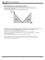
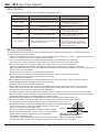
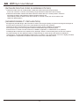
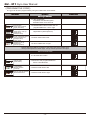
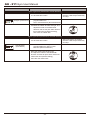
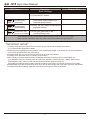
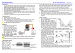
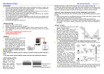
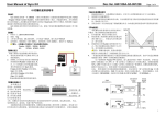
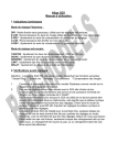
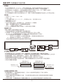
GU 211 陀螺儀使用說明書
《特點》
GU211陀螺儀採用新一代 M.M.S.(微電子機械系統)高級角度感測器件和先進的AVCS
(Angular Vector Control System,角度向量控制系統)演算法,內建溫度補償,
具有高精度的方向控制能力。此陀螺儀兼有普通和方向鎖定(Head lock)兩種工作模式,
利用感度(Gain)通道進行兩種模式的切換及感度值的設定。
GU211陀螺儀採用全數位化的參數設定方式,避免了因電位器機械磨損所造成的工作不穩定現象。
《規格》
1.外形尺寸:26mm x 24mm x 9mm
2.重量:12g
3.工作電壓和電流:DC 4.5-6.5V,工作電流 50mA,最大電流<100mA
4.操作溫度:0℃~65℃
5.操作濕度:0%~95%
6.符合RoHS限用規章,相容標準1520µs與窄頻760µs伺服機
警告:本陀螺儀不相容以下非標準頻率的舵機:
JR:
2700G,8700G,810G
7.GU-211 陀螺儀僅適用數位伺服機,不適用於類比伺服機。
《接線方法》
請按下圖所示連接陀螺儀和其他設備:
1.將舵機控制線插入陀螺儀本體上的舵機線接頭;
2.陀螺儀上引出的2條長線分別插到遙控接收機的Rudder及Gain通道。
黑、紅、白三色線插頭對應Rudder通道,黃色單線插頭對應Gain通道。
Futaba接收機Rudder對應CH4,Gain對應CH5。
(部分Futaba遙控器可自定義各通道連接,請對應遙控器通道設定)
JR 接收機Rudder對應CH4,Gain對應AUX2。
其他品牌遙控器請參照其遙控器使用說明作連接。
Rudder
Gain
《陀螺儀的固定》
本陀螺儀在設計時,內部結構已採取了震動隔離、溫度補償和電磁干擾防護等措施,
但為保證陀螺儀感測器能穩定工作,陀螺儀在安裝時應選擇震動較小且接近機體回轉中心的位置,
請遠離發動機、馬達、電調等震動大、溫度高、電磁干擾嚴重的部位。
為隔離機體震動對感測器的影響,陀螺儀的底部須貼上軟性材料(泡棉貼)。
若發現飛行時有明顯的中點漂移現象,請檢查機體震動情況並安裝好附件中的配重鐵片,
以更好的隔離高頻震動。
配重安裝方式
一般安裝方式
雙面泡棉貼片(薄)
雙面泡棉貼片(薄)
配重鐵片
雙面泡棉貼片(薄)
《油機安裝調整注意》
因油機震動較大,安裝調整應仔細進行,若有中立點漂移現象請從以下幾方面解決:
1.使用附件中的配重鐵片。
2.請用尼龍綁帶固定陀螺儀的引出線,引出線要留有適當的長度以避免將震動傳導至陀螺儀,
影響其正常工作。
3.安裝完成後,在發動機怠速下輕觸陀螺儀外殼,如未感覺到明顯震動即可獲得較好效果。
-1-
GU - 211 Gyro User Manual
《START 》
1.Turn on transmitter and ensure the output signal is in good condition.
2.Set the GAIN value above 50% in transmitter to select Head-Lock Mode.
3.Keep the rudder stick at neutral position, and then power on the gyro
(That means connecting the battery pack to the speed controller to supply the receiver, then the
gyro gets its power supply from the receiver). Don’t move the rudder stick or the helicopter until the
initialization process is completed.
Gyro cannot work properly if it is not initialized with Head-Lock Mode.
Gyro
Sensitvity
100%
50%
Normal
Mode
0%
Head Lock
Mode
50%
100%
Gain
4.Some old transmitters (such as Futaba FF7S, FF6S and T6XHS, etc) don't have the gyro sensitivity switching function,
in such a case, the gyro sensitivity setting is performed by adjusting the ATV of the GAIN channel, and the
mode switching of Head-Lock Mode and Normal Mode is performed by the switch position.
Please read the user manual of your transmitter for reference.
The figure is an example of sensitivity setting with a T6XHS transmitter. In the hovering flight,
(That is: Head-Lock Mode), the gyro sensitivity is set to 72%, and in the Idle-up flight (That is: Normal Mode),
the gyro sensitivity is set to 54%.
The Head-Lock Mode and Normal Mode are switched by the CH5 switch position.
Please always keep in mind that when the sensitivity switching is performed with the ATV setting, the
Head-Lock Mode cannot be used at both side (that means forward position and backward position) of the
CH5 switch for hovering and Idle-up flight.
-2-
GU - 211 Gyro User Manual
《LED STATUS》
Under different working mode, the LEDs on the gyro have different status.
Working Modes
Rudder Stick Conditions
Head-lock Mode
Neutral point
Head-lock Mode
Stick not at neutral position or initialization failed
LED #S: Solid green
Neutral point
Normal Mode
LED Status
LED #S: Solid red, led #1, #2, and
#3 become solid green.
LED #S: Solid red
Normal Mode
Stick not at neutral position or initialization failed
LED #S: Solid red, led #1, #2, and
#3 become solid green.
Failure
No radio signal or initialization faild
LED #S: Solid red, led #1, #2, and
#3 become solid green.
Gyro initialization
Keep rudder stick at neutral position and
ensure fuselage steady
LED #S turns red, and LED#1, #2, and
#3 turn green for one second, then LED
#S becomes green, LED #1, #2, and
#3 turn off If initialization failed, LED #S
becomes solid red, and LED #1, #2, and
#3 become solid green
《SET-UP PROCEDURE》
The installation and set-up process of the gyro are almost same as other brand products. For a better performance,
please read the following instructions.
1.Follow the installation instructions on page 1. Select suitable type of servo(1520µs /760µs )before connecting the
before connecting the tail servo to avoid permanent damage.
2.Turn on transmitter and ensure the GAIN channel sensitivity is more than 50% (that means the
gyro will work in Head-Lock Mode). Put the rudder stick, trimmer and sub-trim at neutral position.
3.Connect the rudder servo to the gyro; switch on the main power, the gyro starts initialization.
When the initialization is completed, LED #S lights solid green means the gyro is working in Head-Lock
Mode, while solid red means the gyro is working in Normal Mode. Please reverse the direction of GAIN channel if the
gyro is working in Normal Mode.
Please read the user manual of your transmitter for reference.
4.Move the fuselage clockwise and anti-clockwise to check the rudder servo horn moving direction.
If wrong direction occurred, please program the gyro correctly.
This is an important operation!
5.Move rudder stick left and right to check the rudder servo horn moving direction. If wrong direction occurred,
please program the gyro at the REV menu of your transmitter.
(Warning: This is an very important operation!)
6.After the above procedures, disconnect the main battery pack to power-off the gyro and then reconnect the
battery pack after a few seconds. Check the gyro again to ensure the rudder will be set to neutral correctly in
head-lock mode (the LED #S is solid green after initialization.).
7.In Head-Lock Mode, make the rudder servo neutrally, and then install the servo horn perpendicular to servo body.
8.Adjust the length of push-rod linkage to make sure that it's perpendicular between the ball-link and push-rod linkage
(90 degree) while the gyro is at neutral position in head-lock mode.
9.Follow the program instructions to adjust the rudder servo travelling limits of left and right side.
10.During the test flight, establish a stable hovering by adjusting the sensitivity value of gain channel.
The suggested value should around 60% to 75% of JR transmitters, 20%~ 30% of
90o
FUTABA transmitters, and the most suitable value is gotten by test flights adjustment.
If there is any tendency for the tail to twitch quickly from side-to-side,
it will be necessary to lower the gain value.
Ball-link position
If the tail is precarious when pitch and throttle is rapidly changed,
please use higher gain value. If you do need to use normal mode,
please switch to normal mode after the gyro completes the
Ball-link position suggestion
Standard servo:12-17mm
initialization in head-lock mode.
Micro or mini servo: 8-15mm
The picture at right side shows the rudder servo in neutral position.
The ball-link position on servo horn should be referred to the user manual of your helicopter.
-3-
GU - 211 Gyro User Manual
《INITIALIZATION THE GYRO IN WORKING STATUS》
1.Reset the rudder servo to neutral position: Shake the rudder stick left and right at least 4
times at an interval of 1 second. (The traveling range should be at least half of the full range)
2.Reset the neutral date of Head-Lock Mode: Move the rudder stick to the neutral position, switch the
transmitter sensitivity switch between Head-Lock Mode position and
Normal Mode position at least 3 times at an interval of 1 second or less, then set the switch to the
Head-Lock Mode position.
《NONRESPONSIBILITY DECLARATION》
R/C flight has potential danger. We have tried our best to use the good quality components and high technologies to
provide superior performance. But for the unpredictable environment and conditions,
customers are also recommended to try their best to maintain proper installation and operation,
ensure power supply and control signal are stable and believable, flight in legal flying field.
In that we have no control over the correct use, installation, application, or maintenance of our products,
no liability shall be assumed nor accepted for any damages, losses or costs resulting from the use of the product.
Any claims arising from the operating, failure of malfunctioning etc. will be denied. We assume no liability for
personal injury, consequential damages resulting from our product or our workmanship. As far as is legally permitted,
the obligation to compensation is limited to the invoice amount of the affected product.
-4-
GU - 211 Gyro User Manual
《PROGRAM THE GYRO》
The gyro can be user-programmed by using the rudder stick of transmitter.
LED Status
Operation
Rudder Stick
Servo Type Selection
1.1 After initialization
completed, LED #S solid green,
hold SET button for 3 seconds.
LED #1 lights
(Solid Green) LED #S
lights (Solid Red)
1.2 Release SET buttom to enter the 1st
programmable item: Servo Type
LED#1 lights
(Solid Green) 1520 μs
Digital Servo
(wide spectrum)
1.3 Move rudder stick to right 1520. μs
Digital Servo (wide spectrum)
LED#1 lights(Solid Green)
1520 μs Digital Servo
(wide spectrum)
1.4 Move rudder stick to left.
LED#1 lights
(Solid Red) 760 μs
Digital Servo
(narrow spectrum)
1.5 Move rudder stick to right.
Please adjust the LED #1 according to the frame rate of the rudder servo.
1520 μs wide spectrum: Green light, 760 μs narrow spectrum: Red light.
Servo Travel Direction
2.1 Click the SET buttom
LED #1 off (Solid Green)
LED #2 lights
(Solid Green)
2.2 Enter the 2nd programmable item:
Servo Travel Direction
LED #2 lights
(Solid Green).
Normal Direction
(Default).
2.3 Move rudder stick to left
LED #2 lights (Solid Red).
Reversed Direction
2.4 Move rudder stick to right
-5-
GU - 211 Gyro User Manual
LED Status
Operation
Rudder Stick
Servo Type Limit (Travel limit of normal direction)
3.1 Click the SET buttom
LED #2 off. LED
#3 lights (Solid Green)
* Servo will shift to the positive
direction a little bit spontaneously
and stop.
3.2 Enter the 1st section og 3nd
programmable item:
Servo Travel Direction (Normal Direction)
3.3 Move the rudder stick left and right, and
adjust the rudder to the POSITIVE
direction until the tail pitch slider reaches
its mechanical end (without binding),
then ceter the rudder stick.
Servo Type Limit (Travel limit of reversed direction)
3.4 Click the SET buttom
LED #3 lights
(Solid Green)
3.5 Enter the 2nd section og 3nd
programmable item: Servo Travel
Direction (Reverse Direction)
Move the rudder stick left and right,
and adjust the rudder to the REVERSE
direction until the tail pitch slider reaches its
mechanical end (without binding),
then ceter the rudder stick.
-6-
* Servo will shift to the reverse
direction a little bit spontaneously
and stop.
GU - 211 Gyro User Manual
LED Status
Operation
Save Settings
Rudder Stick
4.1 Click the SET buttom
LED #S.1.2.3 light
simultaneously
(Solid RED)
4.2 All the prepared settings are ready
to be saved, and the servo horn
centered spontaneously.
LED #S.1.2.3 light
simultaneously
(Solid GREEN)
4.3 Click the SET buttom to save all the
prepared settings.
LED #1.2.3 off
simultaneously, LED
#S lights (Solid GREEN)
4.4 The gyro goes bace to the
normal working mode.
As all settings are being saved, please power off the gyro and power it on once again.
Make sure the mechanism works fine and the servo horn shifts to the right direction.
《IMPORTANT NOTES》
1.Carefully check the servo type before connecting it to gyro. Never use an analog servo with the
gyro programmed to Digital Servo Mode.
2.Please place the fuselage to the flying field for a few minutes before flight. It can let the gyro to accommodate the
environment temperature for best performance.
3.Carefully fasten the gyro wire and remain extra length to avoid extra vibration
4.Carefully check the rudder servo to maintain good condition
5.When the Gyro Is interfered accidentally, the LED #S will change to Orange color and flash slowly, the
gyro will quickly resume to working status to avoid crash. Normally, the resuming time <100ms. After landing,
please click the “SET” button to clear the LED #S alarm. Please check the wiring, the
flying field circumstance and the battery carefully to search for the reason of interference before the next flight.
6.Please adjust the rudder channel travel range (ATV) at both left and right side to get better symmetry and linearity.
7.Carefully check all the settings, data and connections before flight to avoid any accident.
-7-