1
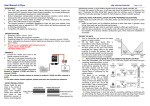
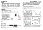
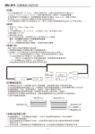
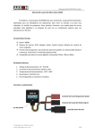
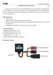
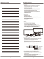
GU - 211 Gyro User Manual
GU - 211 Gyro User Manual
《FEATURES》
1.This Gyro uses advanced MEMS (Micro Electro Mechanical Systems) angular rate sensor and
AVCS (Angular Vector Control System) algorithm. It is a super performance, compact,
light weight gyro developed for model helicopter.
2.Built-in temperature compensation provides high-precision direction control ability to eliminate the
drift caused by environment temperature change.
3.Dual working mode: Normal Mode and Head-Lock Mode, switched by the sensitivity value of the
GAIN channel of your transmitter.
4.The program process is completely digitalized to make the gyro more reliable.
Each programmable value is adjusted by a “SET” button without any analog component such as
trimming potentiometer.
5.Compatible with digital and analog servo.
《SPECIFICATION》
1.Dimension: 26mm * 24mm * 9mm
2.Weight: 12g (wires and connectors included)
3.Operating voltage DC 4.5-6.5V, operating current ≈ 50mA, maximum current <100mA
4.Servo: Analog Servos (frequency 50Hz), digital Servos (frequency 333Hz), servo neutral point: 1520us
This gyro is not compatible with following servos:
Futaba- S9251, S9256, BLS251
JR-2700G, 8700G, 810G
《WIRING》
1.Connect the rudder servo lead to the female connector on the gyro.
2.There are 2 male leads coming from the gyro, the lead with black,
red and white wires is plugged into the Rudder channel of your receiver,
and the lead with one single orange wire is plugged into the Gain channel of your receiver.
For Futaba receiver, Rudder channel is located in channel 4 (CH4) and Gain in channel 5 (CH5).
For JR receiver, Rudder channel is located in channel 3 (CH3) and Gain channel in AUX2.
For other remote control systems, please read their user manuals for reference.
Rudder
Gain
《GYRO INSTALLATION》
Please install the gyro close to the centre of fuselage and keep away from vibration. Please don’t install the
gyro close to heat generation sources, or strong electromagnetic interference sources,
or high vibration sources such as motor, speed controller, etc.
To isolate the vibration to the gyro, a soft foam pad should be attached on the bottom of the gyro.
If helicopter tail drifts during flight, please check the vibration source of fuselage and install the metal plate
(package included) for high frequency vibration isolation purpose.
Normal lnstallation
lnstallation With Steel Plate
Adhesive foam pad (Thin)
Adhesive foam pad
(Thin)
Steel plate
Adhesive foam pad (Thin)
《SPECIAL HINTS FOR INSTALLATION ON NITRO-POWERED HELICOPTER》
Please Install and handle with care. If tail drifts, please use the following methods for trouble shooting.
1.Install the steel plate, and try difference thickness of foam tape pads. In general, using thinner foam pads can
provide better performance.
2.Carefully fasten the gyro wires to avoid extra vibrations that affect gyro performance.
3.After the above operations, run the engine under idle speed and touch the gyro case to test vibration.
If no obvious vibration conducted to gyro, the installation is successful.
-8-
-1-
GU - 211 Gyro User Manual
GU - 211 Gyro User Manual
《START TO USE》
LED Status
1.Turn on transmitter and ensure the output signal is in good condition.
2.Set the GAIN value above 50% in transmitter to select Head-Lock Mode.
3.Keep the rudder stick at neutral position, and then power on the gyro
(That means connecting the battery pack to the speed controller to supply the receiver, then the
gyro gets its power supply from the receiver). Don’t move the rudder stick or the helicopter until the
initialization process is completed.
Gyro cannot work properly if it is not initialized with Head-Lock Mode.
Gyro
Sensitvity
100%
50%
Normal
Mode
Head Lock
Mode
0%
50%
Operation
Save Settings
4.1 Click SET button
LED #S.1.2.3
light simultaneously
(Solid RED)
4.2 All the prepared settings are ready
to be saved
Note: All modifications will be canceled if the
power supply is cut
LED #S.1.2.3
light simultaneously
(Solid Green)
4.3 Click SET button to save all the prepared settings
LED #S.1.2.3 off
LED #S lights
(Solid Green)
4.4 The gyro goes back to the normal working mode
《IMPORTANT NOTES》
100%
Gain
4.Some old transmitters (such as Futaba FF7S, FF6S and T6XHS, etc) haven’t the gyro sensitivity switching function,
in such a case, the gyro sensitivity setting is performed by adjusting the ATV of the GAIN channel, and the
mode switching of Head-Lock Mode and Normal Mode is performed by the switch position.
The figure is an example of sensitivity setting with a T6XHS transmitter. In the hovering flight,
(That is: Head-Lock Mode), the gyro sensitivity is set to 72%, and in the Idle-up flight (That is: Normal Mode),
the gyro sensitivity is set to 54%.
The Head-Lock Mode and Normal Mode are switched by the CH5 switch position.
1.Carefully check the servo type before connecting it to gyro. Never use an analog servo with the
gyro programmed to Digital Servo Mode.
2.Please place the fuselage to the flying field for a few minutes before flight. It can let the gyro to accommodate the
environment temperature for best performance.
3.Carefully fasten the gyro wire and remain extra length to avoid extra vibration
4.Carefully check the rudder servo to maintain good condition
5.When the Gyro Is interfered accidentally, the LED #S will change to Orange color and flash slowly, the
gyro will quickly resume to working status to avoid crash. Normally, the resuming time <100ms. After landing,
please click the “SET” button to clear the LED #S alarm. Please check the wiring, the
flying field circumstance and the battery carefully to search for the reason of interference before the next flight.
6.Please adjust the rudder channel travel range (ATV) at both left and right side to get better symmetry and linearity.
7.Carefully check all the settings, data and connections before flight to avoid any accident.
Please always keep in mind that when the sensitivity switching is performed with the ATV setting, the
Head-Lock Mode cannot be used at both side (that means forward position and backward position) of the
CH5 switch for hovering and Idle-up flight.
CH5
Sensitivity
Switch
Transmitter
ATV Setting
100%
Transmitter
Setting
Forward
Position
Gyro
Setting
100%
CH 1 2 3 4 5 6
ATV
50%
Head Lock
Mode 72%
R/U%
72
0%
0%
CH 1 2 3 4 5 6
Normal Lock
Mode 54%
%
Backward
Position
ATV
50%
54
100%
-2-
Rudder Stick
-7-
GU - 211 Gyro User Manual
LED Status
GU - 211 Gyro User Manual
Operation
Servo Type Limit (Travel limit of normal direction)
Rudder Stick
《LED STATUS》
Under different working mode, the LEDs on the gyro have different status.
3.1 Click SET button
LED #2 off
LED #3 lights
(Solid Green)
3.2 Enter the step 1 of the 3rd
programmable item
Servo Travel Limit of Normal Direction
Servo horn turns
(Anti clockwise)
3.3 Move rudder stick to left
Servo horn
stops moving
3.4 Move rudder stick to center
Servo horn turns
(Clockwise)
3.5 Move rudder stick to right
Working Modes
Rudder Stick Conditions
Head-lock Mode
Head-lock Mode
Neutral point
Normal Mode
Failure
Gyro initialization
LED #S: Solid green
Stick not at neutral position or initialization failed
Normal Mode
LED Status
Neutral point
LED #S: Green, rapidly flashes 2 times
LED #S: Solid red
Stick not at neutral position or initialization failed
No radio signal or initialization faile
Keep rudder stick at neutral position and
ensure fuselage steady
LED #S: Red, rapidly flashes 2 times
LED #S: Orange, slowly flashes
All LEDs light, red for 0.5 second then
turn to green for 1 second, then
LED #1, #2, #3 turn-off, LED #S solid green.
If initialization failed, LED #1, #2 and #3
become solid green, and LED #S flashes
slowly with Orange color.
Servo Type Limit (Travel limit of reversed direction)
3.6 Click SET button
舵片移動
LED #3 lights
(Solid Red)
3.7 Enter the step 2 of the 3rd
programmable item:
Servo Travel Limit of Reversed Direction
Servo horn turns
(Clockwise)
3.8 Move rudder stick to left
Servo horn
stops moving
3.9 Move rudder stick to center
Servo horn turns
(Anti-clockwise)
3.10 Move rudder stick to right
-6-
《SET-UP PROCEDURE》
The installation and set-up process of the gyro are almost same as other brand products. For a better performance,
please read the following instructions.
1.Follow the installation instructions on page 1. Select suitable type of servo (digital/analog) before connecting the
tail servo to avoid permanent damage.
2.Turn on transmitter and ensure the GAIN channel sensitivity is more than 50% (that means the
gyro will work in Head-Lock Mode). Put the rudder stick, trimmer and sub-trim at neutral position.
3.Connect the rudder servo to the gyro; switch on the main power, the gyro starts initialization.
When the initialization is completed, LED #S lights solid green means the gyro is working in Head-Lock
Mode, while solid red means the gyro is working in Normal Mode. Please reverse the direction of GAIN channel if the
gyro is working in Normal Mode.
4.Move the fuselage clockwise and anti-clockwise to check the rudder servo horn moving direction.
If wrong direction occurred, please program the gyro correctly.
This is an important operation!
5.Move rudder stick left and right to check the rudder servo horn moving direction. If wrong direction occurred,
please program the gyro correctly.
This is an important operation!
6.After the above procedures, disconnect the main battery pack to power-off the gyro and then reconnect the
battery pack after a few seconds. Check the gyro again to ensure the LED #S is solid green after initialization.
7.In Head-Lock Mode, make the rudder servo neutrally, and then install the servo horn perpendicular to servo body.
8.Adjust the length of push-rod linkage to achieve stable hovering in the normal mode.
9.Follow the program instructions to adjust the rudder servo travelling limits of left and right side.
10.During the test flight, establish a stable hovering by adjusting the sensitivity value of gain channel.
The suggested value should around 65% to 70%, the
most suitable value is gotten by test flights adjustment.
If there is any tendency for the tail to twitch quickly from side-to-side,
it will be necessary to lower the gain value.
Ball-link position
If the tail is precarious when pitch and throttle is rapidly changed,
please use higher gain value. If you do need to use normal mode,
please switch to normal mode after the gyro completes the
Ball-link position suggestion
Standard servo:12-17mm
initialization in head-lock mode.
The picture at right side shows the rudder servo in neutral position. Micro or mini servo: 8-15mm
The ball-link position on servo horn should be referred to the user manual of your helicopter.
-3-
GU - 211 Gyro User Manual
GU - 211 Gyro User Manual
《INITIALIZATION THE GYRO IN WORKING STATUS》
1.Reset the rudder servo to neutral position: Shake the rudder stick left and right at least 4
times at an interval of 1 second. (The traveling range should be at least half of the full range)
2.Reset the neutral date of Head-Lock Mode: Move the rudder stick to the neutral position, switch the
transmitter sensitivity switch between Head-Lock Mode position and
Normal Mode position at least 3 times at an interval of 1 second or less, then set the switch to the
Head-Lock Mode position.
《NONRESPONSIBILITY DECLARATION》
R/C flight has potential danger. We have tried our best to use the good quality components and high technologies to
provide superior performance. But for the unpredictable environment and conditions,
customers are also recommended to try their best to maintain proper installation and operation,
ensure power supply and control signal are stable and believable, flight in legal flying field.
In that we have no control over the correct use, installation, application, or maintenance of our products,
no liability shall be assumed nor accepted for any damages, losses or costs resulting from the use of the product.
Any claims arising from the operating, failure of malfunctioning etc. will be denied. We assume no liability for
personal injury, consequential damages resulting from our product or our workmanship. As far as is legally permitted,
the obligation to compensation is limited to the invoice amount of the affected product.
《PROGRAM THE GYRO》
The gyro can be user-programmed by using the rudder stick of transmitter.
LED Status
Operation
Servo Type Selection
1.1 After initialization completed,
hold SET button for 3 seconds.
LED #S lights
(Solid Orange)
1.2 LED #S lights (solid Orange), that means
PROGRAM mode is activated.
LED #1 lights
(Solid Green)
1.3 Release SET button to enter the 1st
programmable item:
Servo Type
LED #1 lights
(Solid Green)
1.4 Move rudder stick to left.
LED #1 lights
(Solid Red)
Analog Servo
1.5 Move rudder stick to right.
Servo Travel Direction
2.1 Click SET buttion
LED #1 off
LED #2 lights
(Solid Green)
2.2 Enter the 2nd progammable item:
Servo Travel Direction
LED #2 lights
(Solid Green)
2.3 Move rudder stick to left
Normal Direction (Default)
LED #2 lights
(Solid Red)
2.4 Move rudder stick to right
Reversed Direction
-4-
-5-
Rudder Stick