1
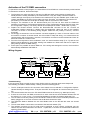
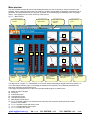
1 DIGITAL MULTIMETER DMK32-62 REMOTE CONTROL SOFTWARE MANUAL [email protected] 64 : ب.ص 031-2227638 : فاكس lovato - DMK 031- 2480780 : هاتف حمص 2 DIGITAL MULTIMETER DMK32-62 REMOTE CONTROL SOFTWARE MANUAL SUMMARY Introduction................................................................................................................................................ 3 Minimum PC hardware requirements ........................................................................................................ 3 Installation.................................................................................................................................................. 3 Activation of the PC-ADX connection ....................................................................................................... 4 Wiring diagram ......................................................................................................................................... 4 Basic principles ......................................................................................................................................... 6 Main window .............................................................................................................................................. 7 System configuration ................................................................................................................................ 8 View menu .................................................................................................................................................12 Data log...................................................................................................................................................12 Alarms.....................................................................................................................................................13 Graphs ....................................................................................................................................................14 Harmonics ...............................................................................................................................................15 Front panel ..............................................................................................................................................16 Password ..................................................................................................................................................17 Communication menu ..............................................................................................................................17 Online .....................................................................................................................................................17 Offline .....................................................................................................................................................17 Parameters menu ......................................................................................................................................18 Base setup ..............................................................................................................................................18 Advanced setup.......................................................................................................................................19 Capacitor overload setup .........................................................................................................................19 Serial interface setup ...............................................................................................................................20 Save-Load-Print ......................................................................................................................................20 Page editor ................................................................................................................................................21 Indicator types .........................................................................................................................................25 Objects types ..........................................................................................................................................31 Start page generation ..............................................................................................................................34 [email protected] 64 : ب.ص 031-2227638 : فاكس lovato - DMK 031- 2480780 : هاتف حمص 3 Introduction The remote control software allows to: Graphically show on a PC the measures read from the multimeters, in the form of ‘virtual’ instruments (gauges, bar graphs, displays, counters and more). Periodically sample a set of measurements defined by the user and save them on disk in different formats (MS-Access, ASCII text, MS-Excel). Plot graphs of the sampled measures. Apply alarm thresholds to the sampled measures. Save on disk the alarm and event sequence happened in the multimeters network. Show a ‘virtual’ front panel of the multimeter, with the possibility to view all the readings and to click on the pushbuttons. Show, modify, save on disk, reload and print the multimeter setup settings. Display a graph of the voltage and current harmonic content, using the FFT readings supplied by the multimeter. Customize the software pages, inserting indicators linked to measurements, background pictures, fixed texts, command buttons and more. Change the language of the software menus and commands, selecting among Italian, English, French, German and Spanish. Minimum PC hardware requirements Windows 95/98/2000 operative system. Graphic card with minimum resolution of 800x600, 1024x768 or more recommended. One free serial interface port (COM:) 64Mb of RAM Pentium-like processor or faster CD-ROM drive for installation Installation To proceed with the installation, it is necessary that the PC is already working with the operative system and to have the CD ROM for the software setup. It is also recommended that the user has at least a minimum experience with PCs and Windows environment. The software is supplied on a CD with two diferent setup procedures. Under the Setup1 directory there is a standard setup procedure used with Win95 and Win98 first releases. The Setup2 directory holds a new setup procedure which can be used with Win 98 second release and Win 2000. Setup1: 1. Close all applications 2. Insert the CD in the drive and wait for its recognition. 3. Select Setup1 directory and launch Setup.exe. 4. Click on the square button with the PC icon to start the installation. 5. A dialog box will appear asking for the directory where to install the program. State the new name, if any, in the space. 6. Follow the given instructions. In case the PC indicates that more recent files are already installed, maintain the existing ones, that is answer YES or KEEP. Setup2: 1. Close all applications 2. Insert the CD in the drive and wait for its recognition. 3. Select Setup2 directory and launch dmk.msi. 4. If your PC does not recognize .msi files (microsoft installer), run instmsia.exe. 5. A dialog box will appear asking for the directory where to install the program. State the new name, if any, in the space. 6. Click Next to proceed 7. If at the end of setup process the installation program asks to reboot the Pc, .execute this procedure. [email protected] 64 : ب.ص 031-2227638 : فاكس lovato - DMK 031- 2480780 : هاتف حمص 4 Activation of the PC-DMK connection To operate the remote control program, it is essential the PC and DMK can communicate by serial interface. To activate the serial link, follow these steps: 1. The first step is to make sure the PC has one free RS-232 serial communications interface port. Serial ports are normally indicated by the COM reference. They are usually numbered COM1: to COM4: although the majority of the brands on the market have only two available ports, COM1: and COM2:, identifiable by the 9-pin D-type male connector. Secondly, it is important to choose the PC port bearing in mind that one serial port is already used for the mouse in some cases. 1. Configure the software to use the selected serial port. This can be done when the DMK.exe software is ececuted for the first time and also later, using Configuration-Options-General menu (see the Configuration chapter). The factory default for the serial port is COM1: , 9600 baud, no parity. 2. Prepare the Rs-485 network. Connect the Rs-232/Rs-485 converter to the PC. Connect all multimeters interface terminals in parallel with the twisted-pair cable and then to the interface converter, as shown in the following wiring diagram. Make sure the polarity is correct ( A and B terminals). 3. We strongly recommend to use an interface converter supplied by Lovato. If the user wants to use an interface converter of another brand, we will not able to help with wiring, nor to assure that the communication will work properly. However, the interface converter must be insulated and have an automatic enable line control circuit. 4. From the front keyboard of each multimeter, enter the serial interface setup (P.41 ) and set one different serial address for each DMK, starting from address 01. Make sure that the PC speed an parity settings match the DMK setting. 5. At this point it is possible to launch DMK.exe. If the wiring and settings are correct, the link will be automatically established with DMK 01. Wiring diagram PC TR A B SG NC NO C TR A B SG RS485 NC NO TR A B SG C RS485 RELAY AC-DC SSR DMK32/62 n°31 RELAY AC-DC SSR DMK32/62 n°1 PX1 Troubleshooting If the connection does not work (trying to enter Online mode, the program emits some beeps and automatically proceeds in Offline mode), carefully check the following points: 1. The PC COM port used for the connection must match the one selected in Configuration-OptionsGeneral-Serial port settings menu. That port must NOT be configured as a serial mouse port on the PC. 2. The communication rate set on the PC and all DMKs must be the same (e.g. 9600 bps for both). 3. If there are more than one DMK connected, then each must have a serial address different than all the others (e.g. 01, 02, 03, etc.). To set the serial address, program the relative parameter P.41 4. The converter connection polarity to the RS-485 bus must be correct; all A terminals (marked on the leads), plugged on to one bus connector and the B terminals with the other. 5. The maximum distance between the two most distant units on the RS-485 bus must not exceed 1000 m. 6. The two most distant units must be connected to the terminal resistor (TR). 7. The interface converter on the PC side must be switched on and correctly configured; see the relative technical sheet attached to the device. In particular, it must be set for automatic enable line switching (Data mode). [email protected] 64 : ب.ص 031-2227638 : فاكس lovato - DMK 031- 2480780 : هاتف حمص 5 [email protected] 64 : ب.ص 031-2227638 : فاكس lovato - DMK 031- 2480780 : هاتف حمص 6 Basic principles The working criteria of the program is to cyclically read the measures taken by connected DMKs and to display them in the form of indicators on the PC monitor. Information are grouped in pages that can be selected by the user during connection. When the software is installed, some already-made pages are supplied. The user, if needed, will be able to create new customized pages and/or to modify the existing ones. Pages can be of two types: Pages that groups data coming from different DMKs, for instance to show simultaneously voltage, current, power etc read from different points of a plant, each controlled by one DMK. In this case each indicator displays readings coming from one particular multimeter. Pages with indicators not assigned to one particular multimeter, where the user selects from which multimeter he wants to read data to be shown. In this case it is possible to concentrate many measures all coming from the same DMK (the one selected in that moment). With a simple click, the user can move its attention to another multimeter, and all indicators will be updated with data coming from the newly selected DMK. Most common pages are of the second type. When the software is displaying one of these pages, one dropdown list will be shown allowing the user to select the DMK from which read measurements. In this case other functions will also be enabled, addressed to the selected multimeter, as for instance the access to setup parameters, harmonic contents graph, virtual front panel and so on. Example of a page with data coming from different DMK Example of a page filled with data coming from the same DMK [email protected] 64 : ب.ص 031-2227638 : فاكس lovato - DMK 031- 2480780 : هاتف حمص 7 Main window The main window contains all menus and toolbars that allow the user to access to various functions of the software. Some of these functions that can modify the software and/or DMK configuration are protected by a password, and are disabled when the program is started. In the following figure is displayed the main page aspect , with highlights on the most commonly used controls. Fig 1.1 – Main window ‘7 segment display’ indicator Drop-down box for page selection Drop-down box for multimeter selection Gauge indicator Type 1 G A H B C D E F I J Command buttons ‘Bar graph’ indicator Page refresh rate Communication status of connected DMKs DMK alarm status description Gauge indicator Type 2 The page shown in figure 1.1, called MAIN, is one of the already-made pages supplied with the program. It is a non-associated indicator page, so the displayed measures are referred to the multimeter selected in the drop-down selection box placed top-right. In this page are displayed many of the most important readings given by DMK, that is: A) B) C) D) E) F) G) Phase-to-phase voltages Frequency Total active power Total reactive power Total apparent power DMK digital outputs status L1, L2, L3 phase voltage, with instantaneous maximum and minumum values (HIGH and LOW functions of the DMK). H) L1, L2, L3 phase current with HIGH-LOW. I) L1, L2, L3 displacement power factor J) L1, L2, L3 total power factor [email protected] 64 : ب.ص 031-2227638 : فاكس lovato - DMK 031- 2480780 : هاتف حمص 8 System configuration To access the configuration window it is necessary to enter the password. By default, the password is LOVATO. Click on Password menu, key-in LOVATO and then confirm with OK. The configuration phase is a very important step to correctly define the program operation. In particular, in the case in which are connected more than one multimeter, the user will have to pay attention to the setting of each DMK connected to the network. Before proceeding with the explanation of the various functions of the software, we will examine the configuration window, looking at the meaning of all settings. Figure 2.1 – Configuration-Options-General PC serial port settings Software language selection Default colors for pages and indicators [email protected] 64 : ب.ص 031-2227638 : فاكس lovato - DMK 031- 2480780 : هاتف حمص 9 Figure 2.2 – Configuration-Options-Multimeters Selected DMK Total number of configured DMKs Add a new DMK to the network configuration Enables / disables the serial communication with the selected DMK Selects the previous / next DMK Nominal value setting for the indicator scale (sets 100% of bar graph indicators etc.) Must be set according to the DMK CT and VT ratio settings. Description of the DMK. It is used to identify the multimeter in pages, data log, alrms and more. Maximum value setting for the indicator scale (sets full scale of all indicators) Must be set according to the DMK CT and VT ratio settings. Defines if an alarm message must be stored when digital output 1 trips Same as above, referred to digital output 2 [email protected] Removes the last DMK from the network configuration Text of the alarm to be stored when output 1 trips 64 : ب.ص Text of the alarm to be stored when output 2 trips 031-2227638 : فاكس lovato - DMK 031- 2480780 : هاتف حمص 10 Figure 2.3 - Configuration-Options-Data log Time interval between data log samples / alarms check Defines how many days the data log database will keep sample records. Defines if, in case of the last sample measures are out of alarm bounds, they must be saved in the database even if the recording time interval is not yet elapsed. Time interval between data log sample recording in the database Selects the measure to sample Selects the source multimeter for the measure to be sampled Deletes the selected row from the list. Note: Deleting fields in the data log database structure will mean losing of all currently present records. Adds a row to the data log list, copying the multimeter and the measure selected in the drop-down boxes List of the measures to be sampled. They will be sampled at the same time and will be used for alarms check (see next chapter), graph plots, data export etc. Max 16 measures. [email protected] 64 : ب.ص 031-2227638 : فاكس lovato - DMK 031- 2480780 : هاتف حمص 11 Figure 2.4 - Configuration-Options-Alarms Selects the measure to which apply the thresholds from the list defined in data log window. Maximum threshold value Enables maximum threshold check. Minimum threshold value Enables minimum threshold check List of the alarm checks applied to data log samples [email protected] 64 : ب.ص 031-2227638 : فاكس lovato - DMK 031- 2480780 : هاتف حمص 12 View menu Data log Variables defined in the Data log configuration (Figure 2.3) are sampled cyclically by the software, independently from which page is shown, with an acquisition rate defined by the user with the Sampling period setting. After each sample, data are compared with alarm thresholds defined by the user (if any). The same data are saved in the Data log database with a storing rate defined with Storing period setting. For instance, it is possible to set a sampling period of 5 sec and a storing period of 30 sec. In this case, every 5 sec the software will read all variables defined in the data log configuration list, and will check those among them for which alarm thresholds have been defined. If there are no alarms, once every 30 sec the sample will be stored in a new record of the database. If the option Store alarms has been selected and one of the measures is out of bounds, its value will be saved in the database even if the storing period has not yet elapsed. Obviously, the user can decide to set a storing period equal to the sampling period. In this case, every sample will be saved in the database. When the user defines the Storing period, he must pay attention to the disk space available on its PC. For instance, setting a storing period of 5 sec, a total of 17280 records/day will be added to the database, each one with date, time and value of each variable defined in the data log list. This is the reason why it has been decided to separate the storing from the sampling period. This solution allows to check variables for alarms with a good frequency, but to store them only when they are out of bounds and however, with a slower ratio. To limit the hard disk space occupation, it is possible to eliminate automatically from the database the samples older than a defined number of days. Setting Maintain samples of the last…days to 7, only records of the last week will be kept in the database. Data recorded in the database can be displayed in a table with View-Data log menu, or clicking on the corresponding icon on the toolbar. Figure 3.1 – View-Data log Sample date and time Number of selected records Start / end date and time for extracting records from the database [email protected] Values of the sampled variables Opens the window for defining start and end date 64 : ب.ص Displays all records of the database 031-2227638 : فاكس lovato - DMK Allows to export data in ASCII text format or MSExcel format 031- 2480780 : هاتف Delete selected records from the database. حمص 13 Alarms As described in the previous Alarm configuration page (Figure 2.4), the user has the possibility to apply thresholds (minimum, maximum or both) to the measures sampled with the data log. In the case in which one or more of the values is out of bounds, the alarm condition is always saved in the alarm database with date and time. When the alarm conditions ends, another record will be saved, allowing to define the duration of the abnormal situation. In the Multimeter configuration window (Figure 2.3) it is possible to specify if the DMK digital outputs tip has to be saved as an alarm record into the alarms database. In this case it is possible to freely define the text that will be stored each time the output will be activated. In the same database are stored also some Events, that is something that happened that can help to better understand the alarms sequence. One example of Event can be the activation of the remote control, that is the instant in which the software has been started and thus the measures sampling has been initiated. It is obvious that if the software or the Pc have been left inactive, then some alarm situation may not be found in the alarm recording. The same can happen if one multimeter has been left switched off for a certain period of time. Events are stored in time sequence with alarms, but with the database window the user will be able to select the information with the following criteria: Period in which alarms and events have happened (date-time of start and end) View only alarms, only events, both View alarms/events from one particular multimeter or from all configured multimeters Figure 4.1 – View-alarms Date-Time of alarm or event Select from viewing all only alarms only events [email protected] Number of selected records Select records from a particular multimeter or from all multimeters 64 : ب.ص Record type Event / Alarm Opens the window for defining start and end date 031-2227638 : فاكس lovato - DMK Description of the alarm or event Allows to export data in ASCII text format or MSExcel format Delete selected records from the database. 031- 2480780 : هاتف حمص 14 Graphs The content of the Data log database can be shown in the form of a graph (strip-chart). In this way it is possible to have immediately a global idea of the trend of the most important measures, or to compare on the same graph two measures taken from two different part of the plant. To open the graph window click on View-Graph menu or use the correspondent icon on the toolbar. The operation criteria of this graph is very similar to on oscilloscope. The X-axis (horizontal) represents the time. The horizontal scale is common to all shown traces and is indicated with sample date-time labels . It is possible to plot up to 4 traces simultaneously, selecting them among the measures defined in Data log. The selection is done by the four drop-down boxes, one for each trace color. For each measure it is possible to modify the vertical scale using the + and – pushbuttons. The value of one measure in a certain moment can be calculated looking at the vertical scale division value (one square). If , for instance, the vertical scale is 50V/division and the plot is about at 8 division, then the absolute value of the measure is about 400V. When looking at a graph of this type, it is more important to look at the trend of the measure rather than its absolute value. The graph is 240 divisions wide per 10 division in height. When opened, the window is set to show data of the current date, that is from 00:00:00 of current day up to 00:00:00 of the next day (tomorrow). Using the Select period pushbutton it is possible to select a different period and also to change the horizontal scale resolution. If in the database there is no data for a certain period of time (for instance because the software has been inactive) one straight line is drawn using a dark colour, connecting the two edges of the ‘hole’. Figure 5.1 – View-Graph Select the measure associated to the red trace [email protected] Dark colour = no data available Selects Start / end date and time. Changes horizontal scale. 64 : ب.ص Bright color = sampled data Increase / decrease vertical scale 031-2227638 : فاكس lovato - DMK Scrolls graph horizontally Red trace vertical scale = 50V / division 031- 2480780 : هاتف Prints this window حمص 15 Harmonics DMK series multimeters have the possibility to measure the harmonic content of the voltage and current waveforms, for each phase, by means of an FFT algorithm (Fast Fourier Transform). By means of ViewHarmonics menu, it is possible to display harmonic data on a bar-graph where on the horizontal axis are represented the order of the harmonic, from the 2nd to the 22nd, plus two bars that represents the THD (Total Harmonic Distortion) and RHD (Residual Harmonic Distortion). The vertical axis represents the intensity of each harmonic, expressed as a percentage of the fundamental harmonic. By means of a drop-down box it is possible to select between Voltage and current harmonic analysis. The single phases L1, L2 and L3 are displayed in three different bar colors. Data shown is referred to the currently selected multimeter (see drop-down box in figure 1.1). If the software is showing a page with data coming from different multimeters, then it will not be possible to show the harmonic analysis window. Note: On DMK multimeters the FFT calculation can be disabled in order to have a better acquisition speed. In this case the graph will not show any data. Figure 6.1 – View-Harmonics Multimeter from which data are taken Drop-down box to select Voltage or Current [email protected] L1, L2, L3 color legend. 64 : ب.ص Harmonics data in graphic format Harmonics data in numeric format 031-2227638 : فاكس lovato - DMK Print this window 031- 2480780 : هاتف حمص 16 Front panel With the remote control software it is possible to display on the PC monitor a ‘virtual’ front panel of the DMK. The window can be opened with View-Front panel menu. It will show the panel of the currently selected multimeter, with real-time visualization of displays and leds status. Clicking with the mouse on the pushbuttons, the user will have the same effect as clicking the real DMK buttons, selecting measurements and functions. It will not be possible to access the functions (like entering setup , meters reset etc) that require the simultaneous pression of more than one button or the continuous pression of the same button for a certain period of time. There are two types of front panels, that represents multimeters of DMK3x and DMK6x series. The front panel window shows the front panel that corresponds to the currently selected multimeter. For this reason, it will not be possible to view the front panel window when the software is showing a page with measures coming from different multimeters. Note: The quality of the graphic representation of the front panel may vary according to some PC settings, such as screen resolution, Font size etc. Figure 7.1 – View-Front panel Description of the currently selected multimeter Clicking on the buttons you have the same effect as clicking the real ones. Real-time visualization of displays and LEds [email protected] 64 : ب.ص 031-2227638 : فاكس lovato - DMK 031- 2480780 : هاتف حمص 17 Password When the software is started some of the functions are disabled. By means of the Password menu it is possible to key in the password that will allow access to all functions, including: Modifying remote control software settings Entering a new password Delete records from Alarms and Data log databases Use of the page editor Modify the DMK settings from the remote control Figure 8.1 – Password After the first installation the password is LOVATO. Later, the user will be able to customize its password, using the New Password button and then entering the new desired password two times. Figure 8.2 – New password Communication menu Online The Communication-Online menu allows to re-establish the serial link after it has been stopped by the user with the Offline command. When clicking Online, the software executes a complete scan of all configured DMK, to verify their status. Offline With communication-Offline the user has the possibility to temporarily suspend the serial communication link between the PC and the DMK network. When the software is in Offline mode, all indicators are shown in a disabled status and Alarm checking and Data log are suspended. This command is to be used when, for instance, it is necessary to modify the network wiring or when DMK are to be switched off. The System Offline status is displayed on the main page Toolbar (at the bottom of the main window). The system passes automatically in Offline mode when the user opens the Configuration window or the Page editor. [email protected] 64 : ب.ص 031-2227638 : فاكس lovato - DMK 031- 2480780 : هاتف حمص 18 Parameters menu The multimeters setup settings can be viewed and modified using the Parameters menu. This way of accessing to the DMK setting is far more immediate and easy than using the direct access from the DMK front keyboard, because on the PC window displays: The parameter code Parameter description Set value Bar graph or drop-down box with possible options Parameters are grouped into four menus that follow the structure described on the DMK manual and addendum. The four available menus are: Base setup (basic settings like CT ratio, VT ratio etc.) Advanced setup (settings of the digital outputs) Capacitor overload setup (settings for the capacitor protection function) Serial communication setup (parameters regarding serial interface) Base setup Figure 9.1 – Parameters-Base setup Parameter code Description Transmits the displayed value into the DMK memory. Enabled only with password. [email protected] Numerical value of the parameter. Highlighted in yellow if different from the factory setup. Double-clicking on this box will open a window for setting the parameter with the numeric keyboard. Receives values from the DMK memory and displays them in the window 64 : ب.ص Resets the values to the factory default. 031-2227638 : فاكس lovato - DMK Drop-down box with the possible options Bar-graph. Drag with the mouse pointer to change value of parameter Closes setup window 031- 2480780 : هاتف حمص 19 Advanced setup Figure 9.2 – Parameters-Advanced setup Box for values with a very high range. Double-click to set value. Select: k for value x 1000 M for value x 1000000 Same method of DMK display. Scroll bar to access following parameters Capacitor overload setup Figure 9.3 – Parameters-Capacitor overload setup [email protected] 64 : ب.ص 031-2227638 : فاكس lovato - DMK 031- 2480780 : هاتف حمص 20 Serial interface setup Figure 9.4 – Parameters-Serial interface setup It is not possible to modify serial interface settings THROUGH the serial interface itself. Save-Load-Print Parameters values (of all four menus) can be saved on disk in a ASCII text file, allowing the user to load them in another multimeter in a very fast and comfortable way. This function is useful when it is necessary to program various multimeters with the same settings or when the user wants to keep track of the setting of one particular plant. To save on disk, select Parameters-Save and enter the desired file name. The extension for this type of file is .PAR. To execute the reverse operation, that is transfer a file to the DMK memory, use Parameters-Load menu. It is also possible to have a printout of the settings, useful to archive with the plant documentation, using Parameters-Print menu. [email protected] 64 : ب.ص 031-2227638 : فاكس lovato - DMK 031- 2480780 : هاتف حمص 21 Page editor The Page editor is the part of the remote control software that allows the user to create some custom pages, inserting indicators and fixed objects. This argument, that should be a part of the configuration Chapter, has been left as the last part of the manual because it is intended for experienced users. To open the page editor, enter the password and click on Configuration-Page editor. Please note that during page editing, as during configuration change, the software enters Offline mode, that is the serial communication with the multimeters is stopped. When started, the page editor shows an empty page. With File menu it is possible to execute the common operations of loading, saving and generating a blank new page. The pages used by the remote control software are placed in a directory (named …\PAGES\ENG when the software is set for English language). The pages are loaded and saved only from this directory. For this reason, the Open and Save windows do not appear as the common Windows file open/save dialogs. In the following paragraphs we will explain the functionality of the page editor by means of a very simple example that will create a test page. [email protected] 64 : ب.ص 031-2227638 : فاكس lovato - DMK 031- 2480780 : هاتف حمص 22 Step 1 The first operation that the user can carry out is to define some general properties of its new page, such as the title, the background color, and an optional background picture. For this purpose, use the Page-Properties menu and open the following window: Figure 10.1 – Page-Properties Text that will appear on the tile bar Select the background color Page background color Allows to select the name of the optional page background picture file. Supported formats are .BMP, .JPG and .GIF Background picture graphic file name. Its dimensions must fit the window. Step 2 At this point, the user may want to add to its page one needle indicator that will show the equivalent phase voltage. Select Indicator-Add menu or right-click on an empty point in the page and select Add indicator from the pop-up menu. The following window will be shown: Figure 10.2 Indicator-Add-Indicator type Select one of the available indicator types Click on this button to insert the new indicator [email protected] 64 : ب.ص 031-2227638 : فاكس lovato - DMK 031- 2480780 : هاتف حمص 23 Select the button with the Gauge 1 indicator and then click on the button Add new indicator At this point on the page a new indicator will be shown, with standard position and dimensions. At the same time, the window moves to the basic properties for all indicators: Figure 10.3 – Indicator -Properties Select from which DMK and which measures will be associated to the indicator Indicator position. Coordinates 0,0 are placed at topleft of the window. Objects can also be moved selecting the move tool on the toolbar and dragging them with the mouse Indicator dimensions. Some indicators have fixed Height/Width ratio. In this case adjust dimensions using Width The properties shown in Figure 10.3 are common to all kind of indicators. When specifying the multimeter from which read the measure, please take into account that: If in the Select multimeter drop-down box you choose one of the configured multimeters, the measure displayed by the indicator will always be read from that specific multimeter. This solution must be used when we want to put in the same page measures coming from different multimeters. If the Select multimeter drop-down box is left to Default multimeter , the indicator will show the measure read from the multimeter currently selected in the main page (see figure 1.1). Building one page with all indicators set in this way will enable the user to use the same page with all of the multimeters, one at a time. After having specified position and dimensions of the new indicator, leave the Multimeter selection box to Default multimeter and then select from the possible measures the one that we want for ourexample, that is Equivalent phase voltage. [email protected] 64 : ب.ص 031-2227638 : فاكس lovato - DMK 031- 2480780 : هاتف حمص 24 At this point we can move to the Options page of the Indicator window and fill-in some options for the Gauge 1 indicator type. This Options are different from one indicator to the other. In our case, for example, we can disable the Use default description checkbox and specify a custom description to be placed on our indicator. Figure 10.4 – Indicator-Options (for Gauge1 type indicator) Select if display on the indicator the default measure description or a custom description. Custom description text Custom full scale value Select if the fullscale of the indicator will be the one specified in the multimeter configuration (see figure 2.2) or a custom full scale. Clicking on OK the options are applied and the window is closed. Following the same procedure, it is possible to add other indicators to our page. To modify the properties of an already-placed indicator, select it clicking with the mouse (the indicator is highlighted with a frame) and then use Indicator-Modify menu or right-click and select Modify from the popup menu. In the same way, after having selected one indicator, it is possible to delete it with Delete. Step 3 At this point we have created a very simple page that is ready to be loaded by the software. Let’s save the page with File-Save as , specifying , for instance, TESTPAGE. This command will create a text file, called TESTPAGE.PGD and placed in the …\PAGES\ENG\ directory with the other pages. For whose interested, the file content can be examined and eventually modified with a standard text-editor. Step 4 Now, close the page editor with File-Exit page editor. The program loads the MAIN page (figure 1.1) or the START page (in this case select one of the DMK to move to MAIN page). Now, in the page selection dropdown box we will find our TESTPAGE. Selecting it, the page will be shown and the indicator will display the equivalent phase voltage read from the currently selected multimeter. At this point we have concluded the very minimum sequence to create a custom page. We will now explain the other capabilities of the software that will enable to create more complex pages. [email protected] 64 : ب.ص 031-2227638 : فاكس lovato - DMK 031- 2480780 : هاتف حمص 25 Indicator types Label indicator The label indicator shows one measure in numeric format. Description. Can be the default one or custom. Can also be not displayed. Unit of measure. Can be not displayed. Changes scale automatically (for instance W, kW, MW) Numerical value of the measure. Figure 10.5 – Indicator-Options (for label indicator) [email protected] 64 : ب.ص 031-2227638 : فاكس lovato - DMK 031- 2480780 : هاتف حمص 26 Gauge1 indicator Unit of measure. Scale. Can be the maximum defined for the multimeter (see figure 2.2) or custom. Blue / Yellow linesIndicators for maximum / minimum instantaneous values (function HIGH and LOW of DMK). Available only for certain measures. Numeric value. Description. Can be the default for the measure or custom. Figure 10.6 – Indicator-Options (for Gauge1 indicator) This option is enabled only for measures for which the DMK gives HIGH and LOW function. [email protected] 64 : ب.ص 031-2227638 : فاكس lovato - DMK 031- 2480780 : هاتف حمص 27 Gauge2 indicator It is possible to use the default scale or to customize the minimum and maximum. When associated to Displacement power factor (cosfi) is represented with symmetric scale Figure 10.7 – Indicator-Options (for Gauge2 indicator) [email protected] 64 : ب.ص 031-2227638 : فاكس lovato - DMK 031- 2480780 : هاتف حمص 28 Seven-segment indicator Operation similar to the label indicator, with 7-segment Led display visualization. 3-digits LED display Unit of measure. Changes automatically depending on the value (e.g. W, kW, MW). Figure 10.8 – Indicator-Options (for Seven-segment indicator) [email protected] 64 : ب.ص 031-2227638 : فاكس lovato - DMK 031- 2480780 : هاتف حمص 29 Bar-graph indicator The full scale corresponds to the maximum value defined in Configurationmultimeters (see figure 2.2) The 100% corresponds to the nominal value defined in Configurationmultimeters (see figure 2.2) Numeric value Unit of measure Figure 10.9 – Indicator-Options (for Bar-graphs indicators) [email protected] 64 : ب.ص 031-2227638 : فاكس lovato - DMK 031- 2480780 : هاتف حمص 30 Energy-meter indicator Digits after decimal point are on white background Meter value Unit of measure Figure 10.10 – Indicator-Options (for Energy-meter indicator) [email protected] 64 : ب.ص 031-2227638 : فاكس lovato - DMK 031- 2480780 : هاتف حمص 31 Objects types On a page it is possible to add other objects, some of them fixed (such as fixed texts, lines, pictures etc.) and others with an active function (for instance command buttons). Inserting and editing of these objects is done in the same way as for the indicators. Using Object-Add it is possible to open the window that allows to select the object type and to specify its options. Figure 11.1 – Object-Add The available objects type are Fixed text Rectangle (line) Picture 3D panel Command button Fixed string with customizable colors and dimensions Painted rectangle. Modifying its dimensions is possible to draw lines. Box showing a graphic file Fixed string on a 3D panel Button that can carry out particular functions Just like the indicators, objects have different properties depending on the object type. In the following pages we will explain the function of this properties. [email protected] 64 : ب.ص 031-2227638 : فاكس lovato - DMK 031- 2480780 : هاتف حمص 32 Text Object Inserts a fixed string on the page background. Figure 11.2 – Object-Text-Properties String text Font properties Defines if the string background must be opaque (with its own color) or transparent. Rectangle Object Allows to place a filled rectangle on the page background. Modifying its dimensions it is possible to draw orthogonal lines. Image object Inserts a box displaying a graphic file in BMP, JPG or GIF format. Figure 11.2 – Object-Image-Properties File name Defines if the image has to keep its original dimensions or has to stretch to fit the object dimensions. 3D panel object Similar to the text object, but placed over a 3D-effect panel [email protected] 64 : ب.ص 031-2227638 : فاكس lovato - DMK 031- 2480780 : هاتف حمص 33 Command button object The command button is an active object. Clicking it with the mouse can execute a series of commands selectable by the user. In the Property window, besides the common settings such as position, dimensions, text etc., the user must define also the Action for the command button and an optional Operand for that action. The possible Actions are the following: COMMAND Sends a command to the multimeter. In this case the operand defines the type of command to send. The possible commands are: Reset energy meter Reset HIGH function values Reset LOW function values Reset MAX function values Reset digital output 1 Reset digital output 2 Reset multimeter END Quit the remote control software NEWPAGE Loads a new page. In this case the operand must be selected among one of the existing pages. NEWNODE Selects a new multimeter. In this case the operand must be selected among one of the configured multimeters. PANEL Shows the front panel of the multimeter specified in the operand. Text that appears on the button Figure 11.3 – Object-Command button Box to select the Action for the button Operand connected to the Action Defines if the button is always enabled or only after entering the password. [email protected] 64 : ب.ص 031-2227638 : فاكس lovato - DMK 031- 2480780 : هاتف حمص 34 Start page generation When the software is started, it loads a page with the following criteria: If there is only one DMK in the configuration, the page named ‘MAIN’ is loaded. If there are more than one multimeter, then the program loads the page named ‘START’ These page names are valid when the software is configured in English. The user, if he wants, can customize these pages with the page editor , but it is necessary that the files MAIN.PGD and START.PGD are not deleted. There is the possibility to automatically generate the ‘START’ page, displaying one panel foe each DMK. This operation can be carried out after having finished the configuration phase, opening the page editor and selecting Page-Generate start page. In this way, the software automatically generates the page file START.PGD, inserting for each DMK in the network a panel with: Four label indicators that show Equivalent phase-to-phase voltage Equivalent current Equivalent active power Active energy meter One command button that allows to open the MAIN page selecting the desired DMK . After having generate the page, the user has the possibility to customize it using the common commands of the editor. The following picture shows an example of start page automatically generated for a four-DMK network. At this point he user can add, for instance, a picture with a scheme of its plant and then place the panels in the correct positions. When the software is installed for the first time, it is supplied a START page with only one DMK. This page can be overwritten by the one customized by the user, that will be automatically loaded every time the software is starte [email protected] 64 : ب.ص 031-2227638 : فاكس lovato - DMK 031- 2480780 : هاتف حمص 35 PENTIUM is a registered trademark of Intel Corporation WINDOWS is a registered trademark of Microsoft Corporation [email protected] 64 : ب.ص 031-2227638 : فاكس lovato - DMK 031- 2480780 : هاتف حمص