1
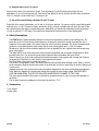
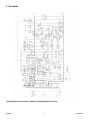
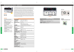
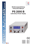
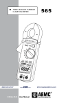
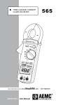
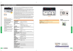
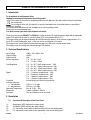
PS3010 - DC-REGULATED POWER SUPPLY
1. Introduction
To all residents of the European Union
Important environmental information about this product
This symbol on the device or the package indicates that disposal of the device after its lifecycle could harm
the environment.
Do not dispose of the unit (or batteries) as unsorted municipal waste; it should be taken to a specialised
company for recycling.
This device should be returned to your distributor or to a local recycling service.
Respect the local environmental rules.
If in doubt, contact your local waste disposal authorities.
Thank you for buying the PS3010! The PS3010 is a highly accurate, DC-regulated power supply with an adjustable
output. This output can be used for constant voltage (C.V.) and constant current (C.C.).
The output voltage can be adjusted between 0V and 30V when the device is in the constant voltage mode or C.V.mode. The current-limiting point (max. ± 12A) can also be set arbitrarily in this mode.
The output current can be adjusted continuously between 0 and 10A in the constant current mode.
The output current and voltage are indicated through LED displays.
2. Technical Specifications
Input Voltage
Output Voltage
Output Current
Source Regulation
Load Regulation
Ripple
Protection
Indication Accuracy
a. Volt-indication
b. Amp-indication
Operating Temperature
Dimensions
Autonomy
: 220V ± 10%, 50Hz ± 2Hz
: 30VDC
: 10A
: C.V. ≤ 2 x 10⁻⁴ + 1mV
C.C. ≤ 2 x 10⁻³ + 10mA
: C.V. ≤ 2 x 10⁻⁴ + 5mV (output current ≤ 10A)
C.V. ≤ 5 x 10⁻⁴ + 10mV (output current > 10A)
C.C. < 2 x 10⁻³ + 15mA (output current ≤ 10A)
C.C. < 5 x 10⁻³ + 20mA (output current > 10A)
: C.V. ≤ 1.5mVrms (output current ≤ 10A)
C.V. ≤ 3.0mVrms (output current > 10A)
C.C. ≤ 10mArms (output current ≤ 10A)
C.C. ≤ 15mArms (output current > 10A)
: current-limiting and short-circuit protection
: LED ± 1% ± 2 digits
: LED ± 2% ± 2 digits
: 0 to 40°C, RH ≤ 90%
: 310mm x 265mm x 165mm
: 8hrs of continuous use at max. load
3. Description
3.1. Controls and Description of the Front Panel
(1)
(2)
(3)
(4)
PS3010
Amp-display (LED): indicates the output current.
Volt-display (LED): indicates the output voltage.
C.C. fine-tuning: rotary switch for the fine-tuning of the current-limiting point.
C.C. adjustment: rotary switch for the adjustment of the current-limiting point.
1
VELLEMAN
(5)
(6)
(7)
(8)
(9)
(10)
(11)
(12)
C.V. adjustment: rotary switch for the adjustment of the output voltage.
C.V. fine-tuning: rotary switch for the fine-tuning of the output voltage.
C.C. indicator: the LED is lit when the device is in the C.C.-mode.
C.V. indicator: the LED is lit when the device is in the C.V.-mode.
Power switch: push-button used to activate/deactivate the device. The device is ON when either the C.C.
LED (7) or the C.V. LED (8) is lit.
Output terminal (+): used for the connection of the load's positive terminal.
Ground connection of the housing: the housing is grounded.
Output terminal (-): used for the connection of the load's negative terminal.
3.2. Operating Procedure
1) Using the device as a C.V. source
Turn adjustments (3) and (4) to the extreme right prior to activating the device. Activate the device. Use adjustment
(5) to obtain a voltage that is close to the desired value. Consequently, you should use fine-tuning adjustment (6) to
install the exact value. The C.V. indicator comes on.
2) Connecting the Load
The load is connected as shown in the figure above. You can read the output current (1) and the output voltage (2)
from the display as soon as the device has been switched on. The C.V. indicator (8) is lit if the device is in the C.V.mode. The C.V. LED is off and the C.C. LED will light if the Amp display indicates a value that exceeds the installed
value. When this happens, the device will automatically go into the current-limiting mode. Install a load that will allow
the device to function normally.
PS3010
2
VELLEMAN
3) Using the device as a C.C. source
Use the power switch (9) to activate the device. Turn adjustments (5) and (6) to the extreme right and turn
adjustments (3) and (4) to the extreme left. Connect the load. Adjust (3) and (4) until the desired current is obtained.
The C.C. indicator is now lit while the C.V. indicator is off.
4) Use of the current-limiting adjustment in the C.V.-mode
Place both of the current adjustments, viz. (3) and (4), in the max. position. You can now set the current-limiting point
arbitrarily (max. ± 12A). Proceed as follows: activate the device, connect a variable load and adjust the load so that
the current matches the desired current-limiting point. Meanwhile, you should also manipulate current-adjustments
(3) and (4) until the C.C. LED lights. The value on the Amp display is identical to the current-limiting point.
4. Safety Prescriptions
- The PS3010 enjoys optimal protection thanks to the short-circuit protection and the current-limiting point. The
power loss in case of short circuit is limited thanks to the protection circuit that controls the power loss of the
transistors in the power supply. This feature keeps the device from being damaged. The device will automatically
go into the current-limiting mode, which means that the current-limiting point (max. ± 12A) is installed.
Nevertheless, the short circuit should be repaired as soon as possible in order to prevent wear and unnecessary
power consumption.
The output will be cut off if the short-circuit occurs between the positive and the negative output terminal, which
prevents power loss. The device will resume normal operation when the problem has been solved.
- Store the device in a dry and well-ventilated environment and wipe it clean regularly with a damp cloth. Remove
the power plug if the device is to be stored for a prolonged period of time.
- Cut off the input voltage prior to cleaning the device.
- This device is a large power source. The device should be well-ventilated when working at max. power in order to
avoid overheating. Keep in mind that the surface of the heat sink is too hot to touch when the device is being used
at max. power.
- Improper operation of the device and an excessive ambient temperature may cause certain internal components
to fail. When this happens, the actual output voltage may exceed the rated output voltage. PROCEED WITH
CAUTION WHEN USING THIS DEVICE AND AVOID UNNECESSARY DAMAGE TO THE LOAD.
- The 3-pins ground terminal of the power cord should be grounded securely in order to ensure safe operation of
the device.
- The fan kicks in when the temperature of the heat sink reaches ± 75°C.
5. Accessories
1 user manual
1 power cable
PS3010
3
VELLEMAN
6. Schematics
The information in this manual is subject to change without prior notice.
PS3010
4
VELLEMAN