1
MITSUBISHI ELECTRIC
MELSEC System Q
Programmable Logic Controllers
Reference Manual
QJ71LP21, QJ72LP25,
QJ71BR11, QJ72BR15
MELSECNET/H Network System
Art. no.: 142030
01 09 2006
SH (NA) -080124
Version J
MITSUBISHI ELECTRIC
INDUSTRIAL AUTOMATION
• SAFETY PRECAUTIONS •
(Always read these instructions before using this equipment.)
Before using this product, please read this manual and the relevant manuals introduced in this manual
carefully and pay full attention to safety to handle the product correctly.
The instructions given in this manual are concerned with this product. For the safety instructions of the
programmable controller system, please read the CPU module user's manual.
In this manual, the safety instructions are ranked as "DANGER" and "CAUTION".
DANGER
Indicates that incorrect handling may cause hazardous conditions,
resulting in death or severe injury.
! CAUTION
Indicates that incorrect handling may cause hazardous conditions,
resulting in medium or slight personal injury or physical damage.
!
Note that the ! CAUTION level may lead to a serious consequence according to the circumstances.
Always follow the instructions of both levels because they are important to personal safety.
Please store this manual in a safe place and make it accessible when required. Always forward it to the
end user.
[Design Precautions]
!
DANGER
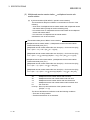
• When the network develops a communication error, the station with the communication error will
enter into the following status.
Use the communication status data to form an interlock circuit in the sequence program that will
operate the system on the safe side. Erroneous output or malfunctioning could cause accidents.
(1) The remote master station will hold the data from before the communication error.
(2) The remote I/O station turns off all outputs. The output module of the remote I/O station can
clear/hold the output status at the time of error by using the remote I/O module parameters.
As the parameters are set to "clear" by default, the output module turns off the outputs at the
time of error. If it is required to hold the output in order to operate the system safely, set the
parameters to "hold".
• If a coaxial cable is disconnected, this may destabilize the line, and a data link communication
error may occur in multiple stations. Make sure to create an interlock circuit in the sequence
program so that the system will operate safely even if the above error occurs. Failure to do so
may result in a serous accident due to faulty output or malfunctions.
A-1
A-1
[Design Precautions]
!
DANGER
• When performing control operations to a PLC (modifying data) in operation by connecting GX
Developer to the CPU module or connecting personal computers to the intelligent functional
modules, configure an interlocking circuit in a sequence program so that the safety of the overall
system is maintained. Also, before performing other control operations (program modifications
and operating status modifications (status control)) on the PLC in operation, be sure to read the
manual thoroughly and confirm the safety. Especially if the above mentioned control operations
are performed from an external device to a remote PLC, problems arising on the PLC side may
not be dealt with immediately due to abnormal data communication. Thus, in addition to
configuring an interlocking circuit in a sequence program, determine how the system should
handle data communication errors between the PLC CPU and external devices.
!
CAUTION
• Always reset the CPU module after changing the parameters for the CPU module or the remote
I/O module. If this is not done, data from before the change could cause malfunctioning.
• Do not bundle the control wires and communication cables with the main circuit or power wires,
or install them close to each other. They should be installed at least 100 mm (3.94 in.) away
from each other. Failure to do so may generate noise that may cause malfunctions.
[Installation Precautions]
!
CAUTION
• Use the PLC in the operating environment that meets the general specifications described in the
user's manual for the CPU module used. Using the PLC in any other operating environments
may cause electric shocks, fires or malfunctions, or may damage or degrade the product.
• While holding the module mounting lever at the bottom of module, insert the module fixing tab
into the fixing hole in the base unit. Then secure the module using the module fixing hole as a
support point.
Incorrect mounting may cause malfunctions, a failure or a drop of the module.
In an environment of frequent vibrations, secure the module with the screw.
Tighten the screw within the specified torque range.
If the screw is too loose, it may cause a drop of the module, a short circuit or malfunctions.
If too tight, it may damage the screw and/or the module, resulting in a drop of the module, a
short circuit or malfunctions.
• Completely turn off the externally supplied power used in the system before mounting or
removing the module. Failure to do so may damage the product.
For remote I/O stations of function version D or later, online module change can be performed.
However, the modules which can be replaced online are limited, and replacement procedures
are determined for each module. For details, refer to the section of online module replacement
in this manual.
A-2
A-2
[Installation Precautions]
!
CAUTION
• Do not directly touch the conducting parts and electronic parts of the module. This may cause
the module to malfunction or fail.
[Wiring Precautions]
!
DANGER
• Completely turn off the externally supplied power used in the system when installing or placing
wiring. Failure to do so may cause electric shocks or damage the product.
!
CAUTION
• Be sure to ground the FG terminals independently for PLC by class D (class 3) or higher.
Failure to do so may cause malfunctions.
• When connecting cables to the terminal block for external power supply, check the rated voltage
and terminal layout of the product for correct wiring.
Connecting a cable to power supply of different rating or incorrect wiring may cause a fire or
fault.
• Tighten the terminal screws with the specified torque.
Loose tightening may lead to a short circuit, fire or malfunction.
• Solder coaxial cable connectors properly. Incomplete soldering may result in malfunctioning.
• Be careful not to let foreign particles such as chaff and wire chips get inside the module. They
may cause a fire, mechanical breakdown or malfunction.
• The top surface of the module is covered with a protective film to prevent foreign objects such as
wire chips from entering the module during wiring work. Do not remove this film until all the
wiring work is complete. Before operating the system, be sure to remove the film to provide
adequate heat ventilation.
• Make sure to place the communication and power cables to be connected to the module in a
duct or fasten them using a clamp. If the cables are not placed in a duct or not fastened with a
clamp, their positions may become unstable and may move, or they may be pulled
inadvertently. This may damage the module and the cables or cause the module to malfunction
because of faulty cable connections.
• When disconnecting the communication and power cables from the module, do not pull the
cables by hand. When disconnecting a cable with a connector, hold the connector to the module
by hand and pull it out to remove the cable. When disconnecting a cable connected to a terminal
block, loosen the screws on the terminal block first before removing the cable. If a cable is
pulled while being connected to the module, it may cause the module to malfunction or damage
the module and cables.
A-3
A-3
[Setup and Maintenance Precautions]
!
CAUTION
• Please read this manual thoroughly and confirm the safety enough before starting online
operations (especially, program modifications, forced outputs, and operating status
modifications), which are performed by connecting GX Developer via the MELSECNET/H
network system to a CPU module running on another station. Performing incorrect online
operations may damage the machinery or result in accidents.
• Never disassemble or modify the module. This may cause breakdowns, malfunctions, injuries or fire.
• Use any radio communication device such as a cellular phone or a PHS phone more than 25cm
(9.85 inch) away in all directions of the PLC.
Not doing so can cause a malfunction.
• Completely turn off the externally supplied power used in the system before mounting or
removing the module. Failure to do so may damage the module or result in malfunctions.
For the remote I/O network systems of function version D or later, online module change can be
performed. However, the modules which can be replaced online are limited, and replacement
procedures are determined for each module. For details, refer to the section of online module
replacement in this manual.
• Do not mount/remove the module onto/from base unit more than 50 times (IEC61131-2compliant), after the first use of the product.
Failure to do so may cause the module to malfunction due to poor contact of connector.
• Do not touch the terminals while the power is on. This may cause breakdowns, malfunctions,
injuries or fire.
• Switch off all phases of the externally supplied power used in the system when cleaning the
module or retightening the terminal or module mounting screws. Failure to completely shut off
all phases of the external power supply may cause module breakdowns and malfunctions. If the
screws are loose, it may cause the module to short-circuit, malfunction or fall off. If the screws
are tightened excessively, it may damage the screws and cause the module to short circuit,
malfunction or fall off.
• Before handling the module, always touch grounded metal, etc. to discharge static electricity
from the human body.
Failure to do so can cause the module to fail or malfunction.
[Disposal Precautions]
!
CAUTION
• When disposing of this product, treat it as industrial waste.
A-4
A-4
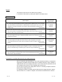
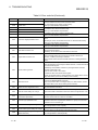
REVISIONS
The manual number is given on the bottom left of the back cover.
Print Date
Manual Number
Revision
Oct., 2000 SH (NA) -080124-A First printing
May., 2001 SH (NA) -080124-B Model addition
QJ71LP21G, QJ72LP25G, QJ71LP21GE, QJ72LP25GE
Correction
Product Components, About The Generic Terms And Abbreviations,
Chapter 1, Section 1.2, 2.4, 3.1.1, 3.1.2, 3.2.1, 3.2.2, 3.3.2, 4.2.1, 4.2.2,
4.8.2, Chapter 5, Section 5.1.5, 5.2.1, 6.1.2, 6.2.1, 6.3, 6.4, 7.1.1, 7.8,
8.1, 8.1.1, 8.1.4, 8.3.1, 8.3.2, Appendix 2, 3, 4, 5, Index
Addition
Section 8.2.6
Apr., 2002 SH (NA) -080124-C Correction
Section 1.2, 1.3, 2.3.1, 2.3.2, 2.3.3, 2.5, 3.1.1, 3.1.2, 3.2, 3.3.2, 4.2.1,
6.1.1, 6.4, Chapter 7, Section 8.4, Appendix 2, 3
Changed item numbers
Section 2.3
Section 2.4, Section 2.4
Section 2.5
Addition
Section 7.10
Nov., 2002 SH (NA) -080124-D Model addition
QJ71LP21S-25
Correction
SAFETY PRECAUTIONS, CONTENTS,
Generic Terms And Abbreviations, Product Components,
Section 1.1, 1.2, 3.1.1, 3.1.2, 4.1.2, 4.8.1, 4.8.2, 7.1.1, 8.1.4,
Appendix 2, 3
Apr., 2003 SH (NA) -080124-E Correction
SAFETY PRECAUTIONS, About Manuals, Section 1.2, 2.1.2, 2.2.2,
2.3.2, 2.5, 3.1.1, 3.1.2, 3.2.2, 3.3.1, Chapter 5, Section 5.1.3, 5.1.5, 6.2,
6.3, 6.4, 6.5, 8.1, 8.2, 8.2.1, 8.2.5, 8.3.1
A-5
A-5
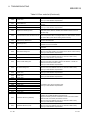
The manual number is given on the bottom left of the back cover.
Print Date
Manual Number
Revision
Jun., 2004 SH (NA) -080124-F Correction
SAFETY PRECAUTIONS, Manuals, Generic Terms And Abbreviations,
Section 1.2, 2.1.2, 2.2.2, 2.3.2, 2.4.2, 2.5, 3.1.1, 3.1.2, 3.1.3, 3.1.4, 3.2,
3.2.2, 4.2.2, 4.9.1, 4.10, 4.10.1, 4.10.2, 4.10.3, Chapter 5, Section 5.1.1,
5.2, 5.2.1, 6.4, 6.5, Chapter 7, Section 8.1, 8.1.1, 8.1.2, 8.1.3, 8.1.4,
8.2.1, 8.2.3, 8.2.5, 8.2.7, 8.3.1, 8.3.2, Appendix 2, 3
Addition
Section 1.4, 2.4, 2.7, 3.3.3, 3.3.4, 7.11, 7.12, 8.2.7, Appendix 7
Changed section No.
Section 2.4
Mar., 2005 SH (NA) -080124-G Correction
Section 2.5, Section 2.5
Section 2.6
Safety Precautions, Conformation to the EMC Directive and Low Voltage
Instruction, Product Configuration, Section 1.1, 1.2, 2.6, 2.7, 3.1.1, 3.1.2,
3.1.4, 3.2.2, 3.3.2, 4.2.1, 4.2.2, 4.3, 4.4, 4.8.1, 4.8.2, 4.9.1, 4.10.1, 5.1.4,
6.1.1, 6.2, 6.2.2, 6.3, 7.4, 8.1, 8.1.2, 8.1.3, 8.2, 8.2.1, 8.3.1, 8.3.2,
Appendix 2, 3, 4, 5, 7
Addition
Section 8.2.8
Sep., 2005 SH (NA) -080124-H Correction
Generic Terms And Abbreviations, Section 1.2, Section 2.5, Section 3.2,
3.2.2, 3.3.2, Section 5.1.5, 5.2.1, Section 6.3, 6.5, Section 7.12, Section
8.2, 8.2.5, 8.3.1, 8.3.2, Appendix 3, 4, 5
May, 2006
SH (NA) -080124-I Correction
Generic Terms And Abbreviations, Section 1.1, Chapter 2, Section 2.2.1,
2.5, 3.1.1, 3.1.4, 4.2.1, 4.2.2, 5.1.3, 5.1.4, 5.1.5, 6.3, 6.4, 7.1.1, 8.1.2,
8.3.2, Appendix 5
Addition
Section 2.5.1, 2.5.2
Sep., 2006 SH (NA) -080124-J Correction
Section 2.1.2, 2.2.2, 2.3.2, 2.4.2, 4.2.1, 4.2.2, 8.3.2
Japanese Manual Version SH-080123-M
This manual confers no industrial property rights or any rights of any other kind, nor does it confer any patent
licenses. Mitsubishi Electric Corporation cannot be held responsible for any problems involving industrial property
rights which may occur as a result of using the contents noted in this manual.
© 2000 MITSUBISHI ELECTRIC CORPORATION
A-6
A-6
INTRODUCTION
Thank you for purchasing the MELSEC-Q series PLC.
Before using the equipment, please read this manual carefully to develop full familiarity with the functions
and performance of the Q series PLC you have purchased, so as to ensure correct use.
Please forward a copy of this manual to the end user.
CONTENTS
SAFETY PRECAUTIONS..............................................................................................................................A- 1
REVISIONS ....................................................................................................................................................A- 5
CONTENTS....................................................................................................................................................A- 7
Manuals
....................................................................................................................................................A-11
Conformation to the EMC Directive and Low Voltage Instruction ................................................................A-11
Generic Terms And Abbreviations.................................................................................................................A-12
Product Components .....................................................................................................................................A-13
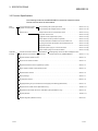
1 OVERVIEW
1.1
1.2
1.3
1.4
1- 1 to 1- 9
Overview.................................................................................................................................................. 1Features .................................................................................................................................................. 1Abbreviations Used in the Text, Tables and Diagrams of This Manual ................................................ 1Functions Added/Changed with Upgrade to Function Version D.......................................................... 1-
2 SYSTEM CONFIGURATION
1
2
9
9
2- 1 to 2-19
2.1 Single Remote I/O Networks .................................................................................................................. 2- 1
2.1.1 Configuration .................................................................................................................................... 2- 1
2.1.2 Setting items..................................................................................................................................... 2- 2
2.1.3 Available device ranges ................................................................................................................... 2- 3
2.2 Multiple Remote I/O Network (QnPHCPU Only).................................................................................... 2- 4
2.2.1 Configuration .................................................................................................................................... 2- 4
2.2.2 Setting items..................................................................................................................................... 2- 5
2.2.3 Available device ranges ................................................................................................................... 2- 6
2.3 Multiplexed Remote I/O Network for Redundant System (QnPRHCPU Only) ..................................... 2- 7
2.3.1 Configuration .................................................................................................................................... 2- 7
2.3.2 Setting items..................................................................................................................................... 2- 8
2.3.3 Available device ranges ................................................................................................................... 2- 9
2.4 Multiple Remote I/O Network.................................................................................................................. 2-10
2.4.1 Configuration .................................................................................................................................... 2-10
2.4.2 Setting items..................................................................................................................................... 2-10
2.4.3 Available device ranges ................................................................................................................... 2-11
2.5 Applicable Systems................................................................................................................................. 2-12
2.5.1 Applicable systems for remote master stations ............................................................................... 2-12
2.5.2 Applicable systems for remote I/O stations...................................................................................... 2-13
2.6 When Using a Multiple CPU System...................................................................................................... 2-16
2.7 Checking Function Version and Serial No. ............................................................................................ 2-18
A-7
A-7
3 SPECIFICATIONS
3- 1 to 3-52
3.1 Performance Specifications .................................................................................................................... 3- 1
3.1.1 Optical loop system performance specifications............................................................................. 3- 1
3.1.2 Coaxial cable system performance specifications .......................................................................... 3- 3
3.1.3 Optical fiber cable specifications ..................................................................................................... 3- 4
3.1.4 Coaxial cable specifications............................................................................................................. 3- 5
3.2 Function Specifications ........................................................................................................................... 3- 8
3.2.1 Cyclic transmission function (Periodic communication).................................................................. 3- 9
(1) Communicating with input/output module....................................................................................... 3- 9
(2) Communicating with intelligent function module............................................................................. 3-10
3.2.2 RAS functions................................................................................................................................... 3-15
(1) Output reset function for communication errors ............................................................................. 3-15
(2) Automatic return function................................................................................................................. 3-15
(3) Loopback function (Optical loop system)........................................................................................ 3-16
(4) Station detach function (Coaxial bus systems)............................................................................... 3-18
(5) Transient transmission enabled even at CPU module error .......................................................... 3-19
(6) Checking the transient transmission abnormal direction time........................................................ 3-20
(7) Diagnostic functions......................................................................................................................... 3-21
(8) Redundant power supply on a remote I/O station .......................................................................... 3-22
(9) Online module change in a remote I/O station ............................................................................... 3-25
3.3 Link Data Send/Receive Processing Time Specifications..................................................................... 3-31
3.3.1 Link data send/receive processing .................................................................................................. 3-31
3.3.2 Transmission delay time .................................................................................................................. 3-34
3.3.3 Switching time from the multiplexed remote master station to the multiplexed remote
sub-master station in a multiplexed remote I/O network................................................................ 3-47
3.3.4 Output holding time during system switching in the multiplexed remote I/O network for
redundant system ............................................................................................................................ 3-48
4 SETUP AND PROCEDURES BEFORE STARTING THE OPERATION
4- 1 to 4-29
4.1 Procedures Before Starting the Operation............................................................................................. 4- 1
4.2 Network Module Names and Settings.................................................................................................... 4- 2
4.2.1 QJ71LP21, QJ71LP21-25, QJ71LP21G, QJ71LP21GE, QJ71BR11 (Remote master station) ... 4- 2
4.2.2 QJ72LP25-25, QJ72LP25G, QJ72LP25GE, QJ72BR15 ............................................................... 4- 5
4.3 Installing and Uninstalling the Module.................................................................................................... 4- 8
4.4 Stopping the CPU (Unintentional Output Prevention) ........................................................................... 4-10
4.5 Checking the Input Power Supply Voltage............................................................................................. 4-10
4.6 Powering On............................................................................................................................................ 4-10
4.6.1 Checking the on status of the POWER LED of the power supply module .................................... 4-10
4.6.2 Checking the on status of the RUN LED of the network module ................................................... 4-10
4.7 Standalone Check of the Network Module (Offline Tests) .................................................................... 4-11
4.7.1 Self-loopback test............................................................................................................................. 4-12
4.7.2 Internal self-loopback test ................................................................................................................ 4-13
4.7.3 Hardware test ................................................................................................................................... 4-14
4.8 Cable Connections.................................................................................................................................. 4-15
4.8.1 Optical loop system.......................................................................................................................... 4-15
4.8.2 Coaxial bus system .......................................................................................................................... 4-17
4.9 Offline Tests from GX Developer............................................................................................................ 4-22
A-8
A-8
4.9.1 Forward loop/reverse loop test (Remote master station only)........................................................ 4-22
4.10 Network Diagnostics from GX Developer (Online Tests) .................................................................... 4-25
4.10.1 Loop test (optical loop system only) .............................................................................................. 4-26
4.10.2 Setup confirmation test .................................................................................................................. 4-27
4.10.3 Station order check test (optical loop system only) ...................................................................... 4-28
4.10.4 Communication test ....................................................................................................................... 4-29
5 PARAMETER SETTINGS
5- 1 to 5-32
5.1 Remote Master Station Parameter Setting ............................................................................................ 5- 5
5.1.1 Setting the number of module cards (Network type) ...................................................................... 5- 5
5.1.2 Network settings............................................................................................................................... 5- 6
(1) Starting I/O No. ................................................................................................................................ 5- 6
(2) Network No. ..................................................................................................................................... 5- 6
(3) Total (slave) stations........................................................................................................................ 5- 6
(4) Group No.
(Can be set for multiplexed remote master station/multiplexed remote sub-master station only) ... 5- 7
(5) Mode ................................................................................................................................................ 5- 7
(6) Parameter setting example ............................................................................................................. 5- 8
5.1.3 Common parameter ......................................................................................................................... 5- 9
(1) LX/LY setting.................................................................................................................................... 5- 9
(2) LB/LW setting................................................................................................................................... 5-12
(3) Reserved station designation .......................................................................................................... 5-13
(4) Remote sub-master station ............................................................................................................. 5-13
5.1.4 Supplemental settings...................................................................................................................... 5-15
5.1.5 Network refresh parameters ............................................................................................................ 5-18
5.1.6 Valid Module During Other Station Access..................................................................................... 5-26
5.1.7 Redundant settings .......................................................................................................................... 5-27
5.2 Remote I/O Station Parameter Settings................................................................................................. 5-28
5.2.1 Remote I/O station possible parameter settings............................................................................. 5-28
6 PROGRAMMING
6- 1 to 6-16
6.1 Programming Precautions ...................................................................................................................... 6- 1
6.1.1 Interlock related signals ................................................................................................................... 6- 1
6.1.2 Program example............................................................................................................................. 6- 4
6.2 Cyclic Transmission ................................................................................................................................ 6- 6
6.2.1 32-bit data guarantee....................................................................................................................... 6- 6
6.2.2 Block guarantee of cyclic data per station....................................................................................... 6- 7
6.3 Communication Between Input/Output Module and Intelligent Function Module................................. 6- 8
6.4 Dedicated Link Instruction List................................................................................................................ 6-12
6.5 Using the Link Special Relays (SB)/ Link Special Registers (SW) ....................................................... 6-16
7 APPLICATION FUNCTIONS
7- 1 to 7-45
7.1 Transient Transmission Function (Non-Periodical Communication)..................................................... 7- 2
7.1.1 Dedicated link instruction ................................................................................................................. 7- 3
(1) Reading/writing remote I/O station intelligent function module buffer memory
(REMFR/REMTO) ............................................................................................................................ 7- 3
7.2 Remote I/O Station System Monitor....................................................................................................... 7-13
A-9
A-9
7.3 Device Test for Remote I/O Station........................................................................................................ 7-14
7.4 Multiplex Transmission Function (Optical Loop System) ...................................................................... 7-16
7.5 Return Sequence Station Number Setting Function.............................................................................. 7-17
7.6 Reserved Station Function ..................................................................................................................... 7-17
7.7 Interrupt Settings..................................................................................................................................... 7-18
7.8 I/O Assignment Function ........................................................................................................................ 7-19
7.9 Stopping/Restarting the Cyclic Transmission and Stopping Link Refreshing (Network Test) ............. 7-20
7.10 Multiplexed remote master function (QnPHCPU only) ........................................................................ 7-21
7.11 Multiplexed remote master function for redundant system (QnPRHCPU only).................................. 7-36
7.11.1 Backup function of master operation on system switching between control system and
standby system................................................................................................................................ 7-37
7.11.2 Master operation by the station that has started up as the control system ................................. 7-38
7.11.3 System switching request function of control system ................................................................... 7-39
7.11.4 Access function by specifying either the control system or standby system ............................... 7-41
7.12 Remote password ................................................................................................................................. 7-42
8 TROUBLESHOOTING
8- 1 to 8-51
8.1 Network Diagnostics (Network Monitor)................................................................................................. 8- 2
8.1.1 Host information ............................................................................................................................... 8- 4
8.1.2 Other station information.................................................................................................................. 8- 6
8.1.3 Network monitor details ................................................................................................................... 8- 8
8.1.4 Error history monitor......................................................................................................................... 8-11
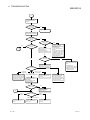
8.2 Troubleshooting ...................................................................................................................................... 8-14
8.2.1 Items to be checked first .................................................................................................................. 8-20
8.2.2 When data link cannot be executed on the entire system.............................................................. 8-20
8.2.3 When data link is disabled because of reset or power off of each station ..................................... 8-21
8.2.4 When a specific-station's data link cannot be executed ................................................................. 8-21
8.2.5 When the transmission and reception data are abnormal.............................................................. 8-22
8.2.6 When the dedicated link instruction is not completed..................................................................... 8-22
8.2.7 When a multiplexed remote I/O network for the redundant system does not operate normally ... 8-23
8.2.8 When checking for reversely inserted fiber-optic cables online ..................................................... 8-24
8.3 Error Codes ............................................................................................................................................. 8-26
8.3.1 MELSECNET/H error code list ........................................................................................................ 8-26
8.3.2 Error codes corresponding to CPU module detected on remote I/O station ................................. 8-38
8.4 H/W Information ...................................................................................................................................... 8-50
APPENDIX
App- 1 to App-50
Appendix 1 Precautions when Changing Over from a MELSECNET/10 Remote I/O Network to
a MELSECNET/H Remote I/O Network................................................................................App- 1
Appendix 2 Link Special Relay (SB) List ..................................................................................................App- 3
Appendix 3 Link Special Register (SW) List.............................................................................................App-11
Appendix 4 Special Relay (SM) for Remote I/O Modules List.................................................................App-28
Appendix 5 Special Register (SD) for Remote I/O Module List...............................................................App-31
Appendix 6 Discontinued Models that can be Mounted on Remote I/O Stations...................................App-44
Appendix 7 External Dimensions..............................................................................................................App-45
INEDX
A - 10
Index- 1 to Index- 2
A - 10
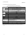
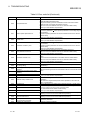
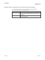
Manuals
The following manuals are also related to this product.
In necessary, order them by quoting the details in the tables below.
Related Manuals
Manual Number
Manual Name
(Model Code)
Q Corresponding MELSECNET/H Network System Reference Manual (PLC to PLC network)
This manual describes the specifications for a MELSECNET/H network system for PLC to PLC network.
It explains the procedures and settings up to operation, setting the parameters, programming and
troubleshooting.
SH-080049
(13JF92)
(Sold separately)
QCPU User's Manual (Hardware Design, Maintenance and Inspection)
This manual provides the specifications of the CPU modules, power supply modules, base units,
extension cables, memory cards and others.
(Sold separately)
QCPU User's Manual (Function Explanation, Program Fundamentals)
This manual explains the functions, programming methods, devices and so necessary to create
programs with the QCPU.
(Sold separately)
SH-080483ENG
(13JR73)
SH-080484ENG
(13JR74)
QCPU User's Manual (Multiple CPU System)
This manual explains the multiple CPU system overview, system configuration, I/O numbers,
communication between CPU modules, and communication with the I/O modules or intelligent function
modules.
SH-080485ENG
(13JR75)
(Sold separately)
QnPRHCPU User's Manual (Redundant System)
This manual explains the redundant system configuration, functions, communication with external
devices, and troubleshooting for redundant system construction using the Redundant CPU.
SH-080486ENG
(13JR76)
(Sold separately)
GX Developer Version 8 Operating Manual
This manual describes the programming, printing, monitoring and debugging procedures, and other
online functions using GX Developer.
(Sold separately)
SH-080373E
(13JU41)
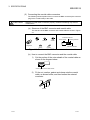
Conformation to the EMC Directive and Low Voltage Instruction
When incorporating the Mitsubishi PLC into other industrial machinery or equipment
and keeping compliance with the EMC and low voltage directives, refer to Chapter 3
"EMC Directive and Low Voltage Instruction" of the User’s Manual (Hardware) for the
CPU module used or the PLC CPU supplied with the base unit.
The CE logo is printed on the rating plate of the PLC, indicating compliance with the
EMC and low voltage directives.
For making this product compliant with the EMC and low voltage directives, please
refer to Section 3.1.3 "Cable" in Chapter 3 of the above-mentioned user’s manual.
A - 11
A - 11
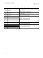
Generic Terms And Abbreviations
Generic term/abbreviation
Description of generic term/abbreviation
QJ71LP21
This is an abbreviation for a QJ71LP21, QJ71LP21-25, QJ71LP21S-25, QJ71LP21G,
QJ71LP21GE MELSECNET/H network module. However, especially in cases to show
different models, QJ71LP21, QJ71LP21-25, QJ71LP21S-25, QJ71LP21G and
QJ71LP21GE are printed.
QJ71BR11
Abbreviation for QJ71BR11 type MELSECNET/H network module.
QJ72LP25
Abbreviation for QJ72LP25-25, QJ72LP25G, QJ72LP25GE MELSECNET/H network
module.
However, especially in cases to show different models, QJ72LP25-25, QJ72LP25G and
QJ72LP25GE are printed.
QJ72BR15
Abbreviation for QJ72BR15 MELSECNET/H network module.
Master module
General term for QJ71LP21 and QJ71BR11.
Remote I/O module
General term for QJ72LP25 and QJ72BR15.
Network module
General term for master module and remote I/O module.
Ethernet module
Abbreviation for QJ71E71-100, QJ71E71-B5, and QJ71E71-B2 Ethernet interface
modules.
Serial communication module
Abbreviation for QJ71C24N, QJ71C24N-R2, QJ71C24N-R4, QJ71C24, and QJ71C24R2 serial communication modules.
MELSECNET/H
Abbreviation for Q series MELSECNET/H network system.
MELSECNET/10
Abbreviation for AnU series MELSECNET/10 network system and QnA/Q4AR series
MELSECNET/10 network system
QCPU
Abbreviation for Q02CPU, Q02HCPU, Q06HCPU, Q12HCPU, Q25HCPU, Q12PHCPU,
Q25PHCPU, Q12PRHCPU, Q25PRHCPU.
QnCPU
Abbreviation for Q02CPU.
QnHCPU
Abbreviation for Q02HCPU, Q06HCPU, Q12HCPU, Q25HCPU.
QnPHCPU
Abbreviation for Q12PHCPU, Q25PHCPU.
QnPRHCPU
Abbreviation for Q12PRHCPU and Q25PRHCPU modules.
QnACPU
Generic term for MELSEC-QnA series CPU modules.
ACPU
Generic term for MELSEC-A series CPU modules.
AnUCPU
Generic term for MELSEC-A series A2UCPU, A2UCPU-S1, A3UCPU, A4UCPU,
A2USCPU, A2USCPU-S1, and A2USHCPU-S1 CPU modules.
Q3 B
Generic term for Q33B, Q35B, Q38B and Q312B main base units.
Q3 SB
Generic term for Q32SB, Q33SB and Q35SB slim type main base units.
Q3 RB
Generic term for Q38RB main base units for the redundant power supply system.
Q5 B
Generic term for Q52B and Q55B extension base units.
Q6 B
Generic term for Q63B, Q65B, Q68B and Q612B extension base units.
Q6 RB
Generic term for Q68RB extension base units for the redundant power supply system.
QA1S6 B
Generic term for QA1S65B and QA1S68B extension base units.
Q6 P
Generic term for Q61P, Q61P-A1, Q61P-A2, Q62P, Q63P and Q64P power supply
modules.
Q6 RP
Generic term for Q61P, Q63RP and Q64RP power supply modules for the redundant
power supply system.
GX Developer
Abbreviation for GX Developer software package.
GX Configurator
Abbreviation for GX Configurator software package.
Tracking cable
Abbreviation for QC10TR and QC30TR tracking cables.
A - 12
A - 12
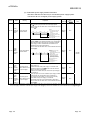
Product Components
Model name
QJ71LP21
QJ71LP21-25
Part name
QJ71LP21 MELSECNET/H Network Module (optical loop type)
QJ71LP21-25 MELSECNET/H Network Module (optical loop type)
QJ71LP21S-25 MELSECNET/H Network Module (optical loop type, with
QJ71LP21S-25
external power supply function)
QJ71LP21G
QJ71LP21G MELSECNET/H Network Module (optical loop type)
QJ71LP21GE QJ71LP21GE MELSECNET/H Network Module (optical loop type)
QJ71BR11 MELSECNET/H Network Module (coaxial bus type)
QJ71BR11
F-type connector
QJ72LP25-25 QJ72LP25-25 MELSECNET/H Network Module (optical loop type)
QJ72LP25G
QJ72LP25G MELSECNET/H Network Module (optical loop type)
QJ72LP25GE QJ72LP25GE MELSECNET/H Network Module (optical loop type)
QJ72BR15 MELSECNET/H Network Module (coaxial cable bus type)
QJ72BR15
F-type connector (A6RCON-F)
Quantity
1
1
1
1
1
1
1
1
1
1
1
1
REMARK
For the coaxial bus system, terminal resistors (75 Ω) are required in the network
terminal stations.
Terminal resistors are not included with the QJ71BR11, QJ72BR15; they must be
purchased separately.
For a list of the model and how to use the terminal resistors, refer to Section 4.8.2.
A - 13
A - 13
1 OVERVIEW
MELSEC-Q
1 OVERVIEW
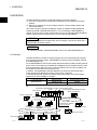
1
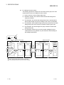
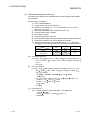
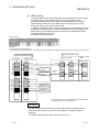
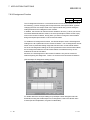
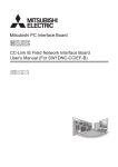
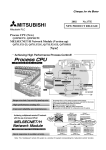
The MELSECNET/H system includes the following 2 types of networks:
1) PLC to PLC network for communications between a control station and normal
stations
2) Remote I/O network for communications between a remote master station and
remote I/O stations
This is the manual to read when building a remote I/O network for MELSECNET/H
systems (hereafter called MELSECNET/H). If you are building a MELSECNET/H
network for PLC to PLC network, please refer to the Q-corresponding MELSECNET/H
network system reference manual. (PLC to PLC network) (SH-080049)
POINT
The Q00JCPU, Q00CPU and Q01CPU cannot configure a remote I/O network in a
MELSECNET/H network system.
REMARK
The previous network, called MELSECNET/10H is now called MELSECNET/H.
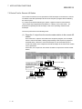
1.1 Overview
The MELSECNET/H remote I/O network system has more functionality and capacity
than the former network system, MELSECNET/10 network system (hereafter referred
to as MELSECNET/10).
As the MELSECNET/H remote I/O network adopts the same module mounting method
as the usual one (mounting I/O modules and intelligent function modules onto the main
base unit/expansion base unit), each module mounted on the remote I/O stations can
be handled in the similar way as the basic one.
In addition, the applicability to the MELSECNET/10 remote I/O network has been
further enhanced so that the FA system can be easily configured.
In the MELSECNET/H remote I/O network optical loop system, the communication
speed can be set to 25 Mbps or 10 Mbps.
Network system
Optical loop 1
Optical loop, coaxial cable
MELSECNET/H
Communication speed
25 Mbps
10 Mbps
1: QJ71LP21-25, QJ71LP21S-25, QJ72LP25-25 only
Control station (MELSECNET/10 mode) Remote master station
QCPU
Control station (MELSECNET/H mode)
GX Developer
QCPU normal station
QCPU normal station
MELSECNET/H (10Mbps)
PLC to PLC network
QnACPU
AnUCPU
QCPU
normal station normal station normal station
MELSECNET/H (25Mbps)
PC network
MELSECNET/H (10Mbps)
remote I/O network
QCPU normal station
MELSECNET/H (25Mbps) remote I/O network
Remote I/O station
Remote I/O station
Remote I/O station
Remote I/O station
GX Developer
1-1
1-1
1 OVERVIEW
MELSEC-Q
POINT
(1) Use QCPU for MELSECNET/H remote I/O network PLC selection time.
(2) Remote I/O networks and PLC to PLC networks cannot be mixed on the same
MELSECNET/H network. Always build separate networks.
(3) Only MELSECNET/H network modules can be connected to a MELSECNET/H
remote I/O network. They cannot be mixed with MELSECNET/10 network
modules (AJ72LP25, A1SJ72QLP25, etc.).
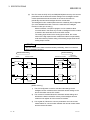
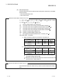
The following table shows the types of networks the CPU modules can be connected to.
CPU module
Network to be connected
Type of networks
that can be used
with CPU
MELSECNET/10
MELSECNET/H
PLC to PLC network
Remote I/O network PLC to PLC network Remote I/O network
(MELSECNET/10 mode)
(MESLECNET/H mode,
MELSECNET/H
Extended mode)
MELSECNET/H
QCPU
(10 Mbps)
MELSECNET/H
(25 Mbps)
AnUCPU
MELSECNET/10
QnACPU
MELSECNET/10
: Can be used
: Cannot be used
1.2 Features
The MELSECNET/H remote I/O network has the following features.
(1) Achievement of a high-speed communication system
(a)
High-speed data sending at a communication rate of 10 Mbps/25 Mbps is
possible.
(25Mbps is available for only the optical loop type QJ71LP21-25,
QJ71LP21S-25 and QJ72LP25-25.)
(2) Large-scale and flexible system configuration
1-2
(a)
The link device has a larger capacity: 16384 points for the link relay (LB)
and 16384 points for the link register (LW). (See Section 2.1.3, "Available
device range settings.")
(b)
A maximum of 4096 I/O points can be set for each remote I/O station.
The link points between a remote master station and a remote I/O station
can be set up to 1600 bytes. The link points of up to 2000 bytes can be set
between a master station and a sub-master station on a multiplexed remote
I/O network.
(c)
Either of the following systems can be chosen: the optical loop system
(maximum total extension of 30 km (98430 ft.)) which has a long station-tostation distance and total distance, and is resistant to noise, or the coaxial
bus system (maximum total extension of 500 m (1640.5 ft.) which can easy
be wired.
(See Section 3.1, "Performance Specifications.")
1-2
1
1 OVERVIEW
MELSEC-Q
(d)
The following functions facilitate network connection:
1) Any station to be connected in the future can be specified as a reserved
station.
Specifying a station not actually connected as a reserved station
prevents a communication error. (See Section 5.1.3 "Common
parameter.")
2) It is not necessary to connect stations in order of the station Nos. in the
network. (See Section 4.2.1, 4.2.2.)
(e)
The parameters can be written to remote I/O modules using GX Developer
in the same way as to CPU modules.
The parameters of the remote I/O module can be used to change the
detailed settings (response time, error output mode) for I/O modules on a
remote I/O station, intelligent function module switch settings and I/O
allocations, and remote password settings.
(Refer to Section 5.2 "Remote I/O Station Parameter Settings".)
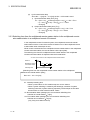
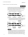
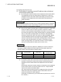
(f)
Setting up a master station (DMR) and a sub-master station (DSMR) on the
multiplexed remote I/O network allows the sub-master station to take over
the control of remote I/O stations (R) in case of the master station's failure.
(The QnPHCPU should be used for the multiplexed remote master station
and sub-master station.)
By making a parameter setting, the multiplexed remote sub-master station
can continue the control of the remote I/O stations even if the master
station has recovered to normal and rejoined to the system. (Setting for the
recovered master station to control the remote I/O stations is also
available.)
(Refer to Section 7.10 "Multiplex Remote Master Function (QnPHCPU
Only)".)
Multiplexed remote
master station (DMR)
Multiplexed remote
sub-master station (DSMR)
Remote I/O station (R) Remote I/O station (R)
1-3
Remote I/O station (R)
1-3
1 OVERVIEW
MELSEC-Q
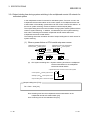
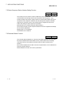
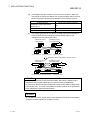
(g)
The redundant system uses the multiplex remote master function to control
I/O modules and intelligent function modules. (The QnPRHCPU should be
used in the redundant system.)
If the multiplexed master station (control system) fails, the multiplex remote
master function will switch the master station from "control system" to
"standby system". At this time, the multiplexed remote sub-master station
is switched from "standby" to "control", continuing the remote I/O control.
The sub-master station (control system) that is controlling the remote I/O
stations will keep its control even if the master station (standby system) has
returned to normal status.
(Refer to Section 7.11 "Multiplex Remote Master Function for Redundant
System (QnPRHCPU Only).)
Multiplexed remote master station (DMR)
Control system Standby system
Multiplexed remote sub-master station (DSMR)
Standby system Control system
Tracking cable
Remote I/O station (R) Remote I/O station (R)
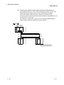
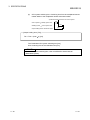
(h)
1-4
Remote I/O station (R)
A maximum of 7 extension base units can be connected to the remote I/O
module (eight base units including the main base unit), allowing the
installation of up to 64 modules.
The maximum overall length of extension cables is 13.2m, ensuring a
flexible layout of extension base units.
1-4
1 OVERVIEW
MELSEC-Q
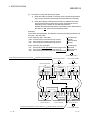
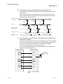
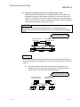
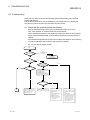
(3) Providing versatile communication service
(a)
Reading and writing of data for an intelligent function module that has been
mounted to a remote I/O station can be easily performed.
There are four methods available for reading and writing.
1)
Use GX Configurator to make the initial settings and automatic refresh
settings in the intelligent function module parameters, and write them
into the remote I/O module in the remote I/O station.
By refreshing the intelligent function module data to the link register W
of the remote I/O module in the auto refresh settings, the remote
master station can read/write refreshed data by cyclic transmission.
Remote I/O station
Remote master station
QCPU
QCPU
Master module
Link register W
Intelligent function module
LW
Intelligent
Remote I/O module function module
Link register LW
Refresh
Link register W
Intelligent function
module parameters
• Initial settings
• Automatic refresh
settings
2)
Buffer memory
Refresh
GX
Configurator
Special link instructions can be used to directly read from or write to the
buffer memory of the intelligent module.
• REMFR instruction: Reads data from the buffer memory of the
remote I/O station intelligent function module.
• REMTO instruction: Writes data to the buffer memory of the remote
I/O station intelligent function module.
REMTO
Remote master station
QCPU
QCPU
Z.REMTO
Remote I/O station
Intelligent function module
Network module
Network module
REMTO
1-5
Intelligent
function module
Buffer memory
1-5
1 OVERVIEW
MELSEC-Q
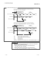
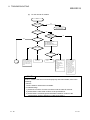
3)
By refreshing the intelligent function module data into the remote I/O
module's data register D by the automatic refresh setting of the
intelligent function module parameters, the remote master station can
read/write data from/to the data register D with READ or WRITE
instruction.
WRITE
Remote I/O station
Remote master station
Intelligent function module
QCPU
QCPU
Master station
Intelligent
Remote I/O module function module
W
Data
Buffer
RI
TE register D
memory
JP.WRITE
Intelligent function
module parameters
• Initial settings
• Automatic refresh
settings
4)
Refresh
GX
Configurator
The automatic refresh setting of the intelligent function parameters
enables the intelligent function module data to be refreshed into the
remote I/O module's data register D. By refreshing the data register D
to the link register W with the parameter of the remote I/O module, the
remote master station can read/write the intelligent function module
data by cyclic transmission.
This method has the advantage that the intelligent function module
parameters created for QCPU can be applied to the remote I/O
module without making any modifications.
Remote I/O station
Remote master station
Intelligent function module
QCPU
QCPU
LW
Master station
Link register W
Intelligent
Remote I/O module function module
Link
Data
Buffer
register W
register D
memory
Link register LW
Refresh
Intelligent function
module parameters
• Initial settings
• Automatic refresh
settings
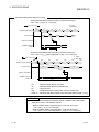
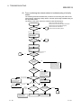
(b)
GX
Configurator
Network module
MELSECNET/H
Condition check
MAIN
Interrupt
sequence
program
IRET
Refresh
The interrupt sequence program of the host's CPU module can be started
up using the event issue function. This function reduces the response time
of the system and enables real-time data reception.
(See Section 7.7, "Starting Up the Interrupt Sequence Program.")
CPU module
I50
Refresh
Normal
sequence
program
Conditions
matched
Interrupt condition
parameters
• Relay information
• Register data
• Network status
Cyclic transmission
END
1-6
1-6
1 OVERVIEW
MELSEC-Q
(4) Enhanced RAS functions (Refer to Section 3.2.2 "RAS functions")
(a)
When a faulty station recovers and can resume normal operation, it
automatically returns to the network to resume the data communication
using the automatic return function.
(b)
By using the loopback function (the optical loop system), it is possible to
continue data transmission among operational stations by disconnecting
faulty areas such as a part of the network where there is a cable
disconnection, a faulty station, etc.
(c)
By using the station detach function (coaxial bus system), even when some
of the connected stations are down due to power off, etc., the normal
communication can be continued among other operational stations.
(d)
The network module can continue the transient transmission even if an error
that stops the CPU module while the system is operating occurs.
(e)
It is possible to check the time when a transient error occurred.
(f)
By mounting 2 power supply modules on a remote I/O station, either of
them can be replaced without powering off the station. (Redundant power
supply on remote I/O station)
The redundant power supply base unit is required for mounting 2 power
supply modules.
(g)
When an input module, an output module or an intelligent function module
mounted on a remote I/O station fails, the faulty module can be replaced
without stopping the system operation. (Online module change)
Online module change is available for Q series I/O modules and function
version D or later analog-to-digital and digital-to-analog converter modules,
temperature input modules and temperature control modules.
REMARK
The following faults make the RAS functions valid.
• Break in cable
• Power-off of slave station
• Network setting error
• Fault detectable by self-diagnostics of CPU module
If the network module has become faulty, the RAS functions may not be activated
depending on the fault.
(5) Control of external connection to remote I/O stations (refer to
Section 7.12)
Setting a remote password for a remote I/O station restricts connections from the
outside via an Ethernet interface module or serial communication module.
(Remote password)
1-7
1-7
1 OVERVIEW
MELSEC-Q
(6) Strengthening network functions
(a)
Remote I/O station
system monitor
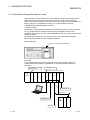
Intelligent function modules mounted to remote I/O stations can be
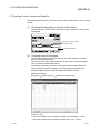
diagnosed using the GX Developer system monitor.
Intelligent function modules mounted to remote I/O stations can be
diagnosed using the system monitor even if it is done via the network using
a GX Developer connected to a remote master station or even if the GX
Developer is directly connected to a remote I/O station.
GX Developer
QCPU
Remote master station
Select
Q64AD
Remote I/O station
Remote I/O station
Q64AD
system monitor
GX Developer
GX Developer
Q64AD
When the network seems to be faulty, it can be diagnosed through GX
Developer connected to the remote master station or remote I/O station.
(b)
If the GX Developer is connected to a remote I/O station, it will not affect the
system operating so user program network function testing can be done online.
It shuts out input (X) from the input module on the remote I/O station and
can turn input (X) on or off using the GX Developer test.
This allows testing of the remote master station input program to be performed.
In addition, it shuts of output (Y) form the remote master station and can
turn remote I/O station output (Y) on and off using the GX Developer test.
This allows testing of the wires for the output module on the remote I/O
station to be performed.
(7) Increased ease of network configuration in combination with Q
corresponding GX Developer
(a)
The network parameters can easily be set by visualising pull-down menus,
dialogue boxes, etc.
(b)
The settings of network Nos., group numbers and operation modes have
been simplified so that these values can be designated only through
software settings.
(Network parameters)
Pull-down menu
Abbreviations
1-8
1-8
1 OVERVIEW
MELSEC-Q
1.3 Abbreviations Used in the Text, Tables and Diagrams of This Manual
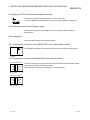
(1) Abbreviations
Abbreviations
Name
MR
Remote master station
R
Remote I/O station
DMR
DSMR
Multiplexed remote master
Multiplexed remote sub-master
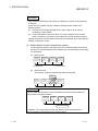
(2) Marking format
Station number (1 to 64)
Abbreviation
Network No. (1 to 239)
[Example]
1) Network No. 3 and remote master station· · · · · · · · · · · · · · · · · · · · 3MR
Station number "0" is not attached to the remote master station.
2) Network No. 5, remote I/O station, station number 3 · · · · · · · · · · · · 5R3
3) Network No. 7, Multiplexed remote sub-master,
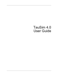
station number 4 · · · · · · · · · · · · · · · · · · · · · · · · · · · · · · · · · · · · 7 DSMR4
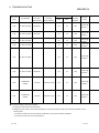
1.4 Functions Added/Changed with Upgrade to Function Version D
The following table lists the additional/altered functions for network modules of function
version D.
Function
Function version
Description
Reference
Multiplexed remote I/O
Allows construction of a multiplexed remote I/O network
network for redundant Function version D
Section 7.11
that includes the redundant system as the master station.
system
Power supply
Allows the construction of the system that includes a
redundancy on remote Function version D remote I/O station in which 2 power supply modules are
I/O station
mounted for power supply redundancy.
Section 3.2.2 (8)
Allows the faulty I/O module or intelligent function module
Online module change
Function version D on a remote I/O station to be replaced online while the
Section 3.2.2 (9)
on remote I/O station
remote I/O station is running.
Remote password for
remote I/O station
1-9
Limits the connection made from GX Developer via the
Ethernet module or serial communication module
Function version D
mounted on a remote I/O station, by setting the
password.
Section 7.12
1-9
2 SYSTEM CONFIGURATION
MELSEC-Q
2 SYSTEM CONFIGURATION
This introduces a system comprised of remote I/O networks.
POINT
(1) Remote I/O networks and PLC to PLC networks cannot be mixed on the same
MELSECNET/H network. Always build separate networks.
(2) Only MELSECNET/H network modules can be connected to a MELSECNET/H
remote I/O network. They cannot be mixed with MELSECNET/10 network
modules (AJ72LP25, A1SJ72QLP25, etc.).
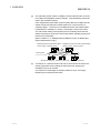
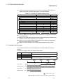
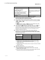
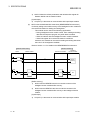
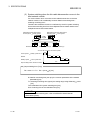
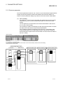
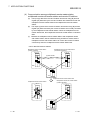
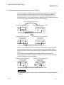
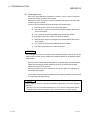
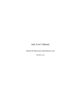
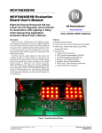
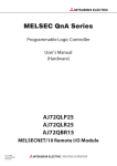
2.1 Single Remote I/O Networks
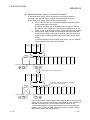
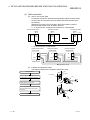
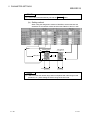
2.1.1 Configuration
(1) Optical loop system
Station number 2
(remote I/O station)
Power supply
QCPU QJ71
LP21
Station number 1
(remote I/O station)
QJ72 I/O I/O
LP25
Power supply
Power supply
Station number 0
(remote master station)
Power supply
Up to 64 remote I/O modules can be connected to a remote master station.
Always set the station number of the remote master station to 0.
QJ72 I/O I/O
LP25
QJ72 I/O I/O
LP25
QJ72 I/O I/O
LP25
Station number 64
(remote I/O station)
Power supply
Power supply
Optical fiber cable
QJ72 I/O I/O
LP25
Station number 4
(remote I/O station)
Station number 3
(remote I/O station)
(2) Coaxial cable bus system
QCPU QJ71
BR11
Station number 1
(remote I/O station)
Station number 32
(remote I/O station)
Power supply
Power supply
Station number 0
(remote master station)
Power supply
Up to 32 remote I/O stations can be connected to a remote master station.
Always set the station number of the remote master station to 0.
QJ72 I/O I/O
BR15
QJ72 I/O I/O
BR15
Coaxial cable
Terminator
(Sold separately)
2-1
Terminator
(Sold separately)
2-1
2
2 SYSTEM CONFIGURATION
MELSEC-Q
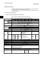
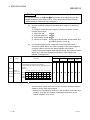
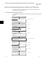
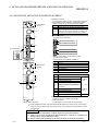
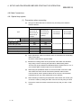
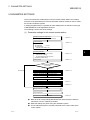
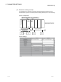
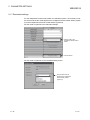
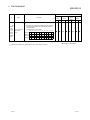
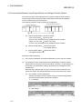
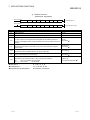
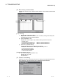
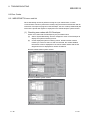
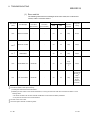
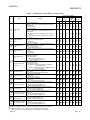
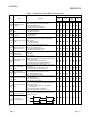
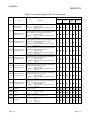
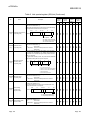
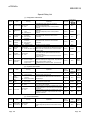
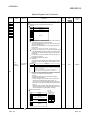
2.1.2 Setting items
(1)
Table 2.1 shows the setting items on the master module of the remote master
station (MR) and the parameter setting items on GX Developer.
Table 2.1 Remote master station setting items
Setting items
2
Remote master station (MR)
Reference
0
Section 4.2.1
Section 4.2.2
Network module switch
STATION NO.
MODE
Parameter setting on GX Developer
MELSECNET/H Ethernet module count setting
MELSECNET/H
(Remote master station)
Network type
Starting I/O No.
Network No.
Total stations
Group No.
Mode
Common parameters
Auxiliary setting
Station specific parameters
Section 5.1.2
Section 5.1.2
Section 5.1.2
—
Section 5.1.2
Section 5.1.3
Section 5.1.4
—
1
Refresh parameters
Valid module during other station access
Interlink transmission parameters
Routing parameters
: Always set,
Section 5.1.1
: Default setting,
Section 5.1.5
Section 5.1.6
—
2
: Set as needed,
: No need to set
1: Default value is not set in LX/LY. Set refresh parameters.
2: Refer to the "Q Corresponding MELSECNET/H Network System Reference
Manual (PLC to PLC Network) (SH-080049)".
2-2
2-2
2 SYSTEM CONFIGURATION
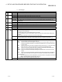
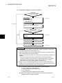
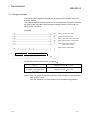
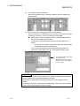
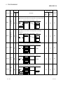
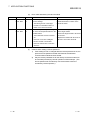
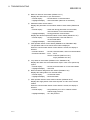
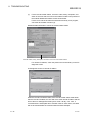
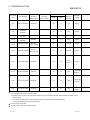
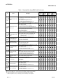
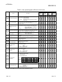
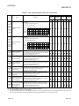
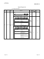
(2)
MELSEC-Q
Table 2.2 shows the setting items on the remote I/O module of the remote I/O
station (R) and the parameter setting items on the GX Developer.
Table 2.2 Remote I/O station setting items
Setting items
Remote I/O station (R)
Reference
1 to 64
Section 4.2.2
Section 4.2.2
Network module switch
STATION NO.
MODE
Parameter setting on GX Developer
PLC system setting
PLC RAS setting
I/O assignment
Operation setting
Ethernet setting
CC-Link setting
Remote password setting
GX Configurator setting
Initial setting
Auto refresh setting
: Always set,
3
3
3
Section 5.2.1
4
5
Section 7.12
6
6
: Default setting,
: Set as needed,
: No need to set
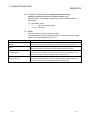
3 : Refer to "QCPU User's Manual (Functional Explanation: Program Fundamentals)
(SH-080484ENG)".
4 : Refer to "Q Corresponding Ethernet Interface Module User's Manual (Basic) (SH080009)". Note that interrupt setting is not available.
5 : Refer to "CC-Link System Master/Local Module User's Manual (SH-080394E)".
Note that interrupt setting is not available.
6 : Refer to the user's manual of the corresponding intelligent function module.
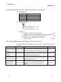
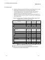
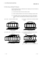
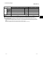
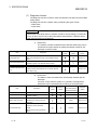
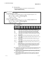
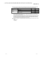
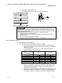
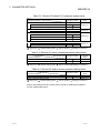
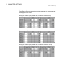
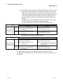
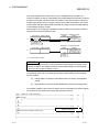
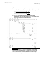
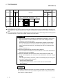
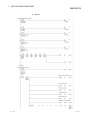
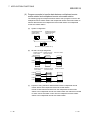
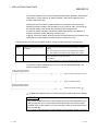
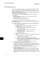
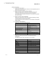
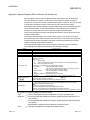
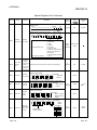
2.1.3 Available device ranges
The remote I/O network can use the following device ranges within each network
module.
These device ranges indicate the remote master station.
Device
Range setting
LB
0H to 3FFFH (16384 points)
LW
0H to 3FFFH (16384 points)
LX
0H to 1FFFH (8192 points) The device range (excluding that of I/O module mounted on the host
0H to 1FFFH (8192 points) station) should be assigned to each network module.
LY
Other
1000H
(4096)
0
CPU module
Network module
CPU module
Network module
—
2000H
(8192)
3000H
(12288)
Extended
B/W
3FFFH
(16383)
1
LB/LW
X/Y
Actual I/O
LX/LY
Actual I/O
: Available device range
1: Expandable by changing from [PLC parameters] - [Device settings]
2-3
2-3
2 SYSTEM CONFIGURATION
MELSEC-Q
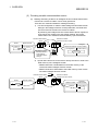
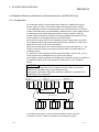
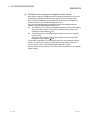
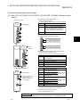
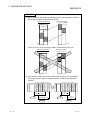
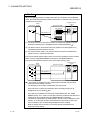
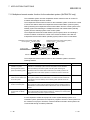
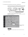
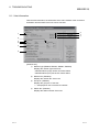
2.2 Multiple Remote I/O Network (QnPHCPU Only)
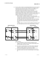
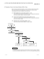
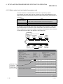
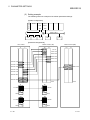
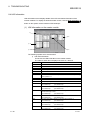
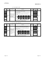
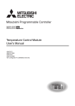
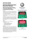
2.2.1 Configuration
A multiplexed remote I/O network system includes a multiplexed remote master station
and a multiplexed remote sub-master station. The multiplexed remote sub-master
station takes control of remote I/O stations when the multiplexed remote master station
fails.
Always assign station No. 0 to the multiplexed remote master station.
It is allowed to assign any of station number 1 to 64 to the multiplexed remote submaster station, provided that the number does not overlap with that of remote I/O
station.
63 remote I/O stations can be connected in an optical loop system, 31 stations in a
coaxial bus system.
POINT
Only the QnPHCPU is the CPU module that works as a multiplexed remote master
station and multiplexed remote sub-master station.
The Q02CPU, Q02HCPU, Q06HCPU, Q12HCPU, Q25HCPU, Q12PRHCPU and
Q25PRHCPU do not work as a multiplexed remote master station and multiplexed
remote sub-master station.
QnPH QJ71
CPU LP21
Power supply
QJ71
LP21
Station No. 2
(Remote I/O station)
QJ72 I/O I/O
LP25
Power supply
QnPH
CPU
Station No. 1
(Multiplexed remote
sub-master station)
Power supply
Power supply
Station No. 0
(Multiplexed remote
master station)
QJ72 I/O I/O
LP25
QJ72 I/O I/O
LP25
Station No. 64
(Remote I/O station)
Power supply
Power supply
Optical fiber cable
QJ72 I/O I/O
LP25
Station No. 4
(Remote I/O station)
Station No. 3
(Remote I/O station)
Up to 63 remote I/O stations can be connected in an optical loop system.
Up to 31 stations can be connected in a coaxial bus system.
2-4
2-4
2 SYSTEM CONFIGURATION
MELSEC-Q
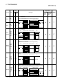
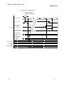
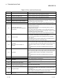
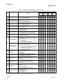
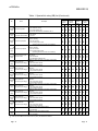
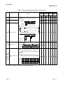
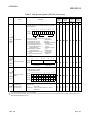
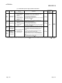
2.2.2 Setting items
(1)
Table 2.3 lists the parameter setting items of the multiplexed remote master
station (DMR) and multiplexed remote sub-master station (DSMR).
Table 2.3 Setting Items of Multiplexed Remote Master Station and
Multiplexed Remote Sub-Master Station
Setting item
Multiplexed remote
master station (DMR)
Multiplexed remote
sub-master station
(DSMR)
Reference
0
1 to 64
Section 4.2.1
Network module switch
STATION NO.
MODE
Section 4.2.1
Parameter setting on GX Developer
MELSECNET/H Ethernet module count setting
Network type
MELSECNET/H
(Multiplexed remote
master station)
MELSECNET/H
(Multiplexed remote
sub-master station)
Starting I/O
Section 5.1.1
Section 5.1.2
Network No.
Section 5.1.2
1
Total stations
Group No.
Section 5.1.2
Section 5.1.2
Mode
Section 5.1.2
1
Common parameters
Auxiliary setting
Section 5.1.3
Section 5.1.4
Station specific parameters
Refresh parameters
—
2
2
Valid module during other
station access
Section 5.1.6
Interlink transmission parameter
—
Routing parameters
: Always set,
Section 5.1.5
3
: Default setting,
: Set as needed,
: No need to set
POINT
1: Set Total stations and common parameters of the multiplexed remote submaster station when using the multiplexed remote sub-master station to
resume the network. The settings must be the same as those of the
multiplexed remote master station.
For example, if the multiplexed remote master station is powered off and then
on during network control by the multiplexed remote sub-master station, the
multiplexed remote sub-master station resumes networking as a master
operating station.
2 : Default value is not set in LX/LY. Set refresh parameters.
3 : Refer to the "Q Corresponding MELSECNET/H Network System Reference
Manual (PLC to PLC Network) (SH-080049)".
2-5
2-5
2 SYSTEM CONFIGURATION
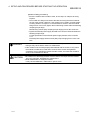
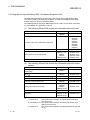
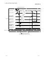
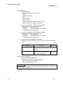
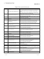
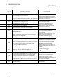
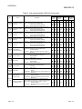
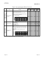
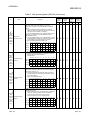
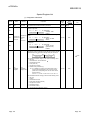
(2)
MELSEC-Q
Table 2.4 lists the setting items can be set on a remote I/O module operating as a
remote I/O station (R) and the parameter setting items can be set from GX
Developer.
Table 2.4 Setting Items of Remote I/O Station
Setting item
Remote I/O station (R)
Reference
1 to 64
Section 4.2.2
Network module main module switch
STATION NO.
MODE
Section 4.2.2
Parameter setting
PLC system setting
4
PLC RAS setting
4
I/O assignment
4
Operation setting
Section 5.1.2
Ethernet setting
5
CC-Link setting
6
Remote password setting
Section 7.12
GX Configurator setting
Initial setting
7
Auto refresh setting
7
: Always set,
: Default setting,
: Set as needed,
: No need to set
4 : Refer to "QCPU User's Manual (Functional Explanation: Program Fundamentals)
(SH-080484ENG)".
5: Refer to "Q Corresponding Ethernet Interface Module User's Manual (Basic) (SH080009)". Note that interrupt setting is not available.
6 : Refer to "CC-Link System Master/Local Module User's Manual (SH-080394E)".
Note that interrupt setting is not available.
7 : Refer to the user's manual of the corresponding intelligent function module.
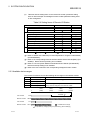
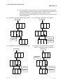
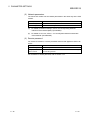
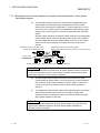
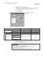
2.2.3 Available device ranges
The remote I/O network can use the following ranges of devices inside network
modules.
Device
Available Range
Others
LB
0H to 3FFFH (16384 points)
LW
0H to 3FFFH (16384 points)
LX
0H to 1FFFH (8192 points)
LY
0H to 1FFFH (8192 points)
Network module
CPU module
Network module
The device range (excluding that of I/O module
mounted on the host station) should be assigned to
each network module.
1000H
(4096)
0
CPU module
—
2000H
(8192)
3000H
(12288)
Extended
B/W
3FFFH
(16383)
1
LB/LW
X/Y
Actual I/O
LX/LY
Actual I/O
: Available device range
1: Expandable by changing from [PLC parameters] - [Device settings]
2-6
2-6
2 SYSTEM CONFIGURATION
MELSEC-Q
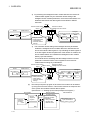
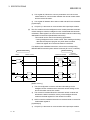
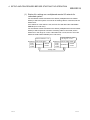
2.3 Multiplexed Remote I/O Network for Redundant System (QnPRHCPU Only)
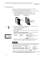
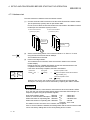
2.3.1 Configuration
The redundant system including QnPRHCPU utilizes the multiplexed remote I/O
network system in order to control I/O modules and intelligent function modules.
In the multiplexed remote I/O network system for the redundant system, the network
module on the side of the control QnPRHCPU (started up as a control system) acts as
a multiplexed remote master station and controls remote I/O stations, while the
network module mounted on the side of the standby QnPRHCPU performs the submaster operation as a multiplexed remote sub-master station.
When the control system CPU or the multiplexed remote master station goes down,
the multiplexed remote sub-master station switches from "standby" to "control" and
takes over the control of the remote I/O stations.
Make sure to assign No.0 to the network module mounted on the system A, i.e., the
system to which the system A connector of tracking cable is connected within the
redundant system.
For station No. of the multiplexed remote sub-master station, set any of No. 1 to 64,
which should not be overlapped with any of remote I/O stations.
The number of remote I/O stations connectable to a multiplexed remote I/O network for
the redundant system is 63 in the optical loop system and 31 in the coaxial bus
system.
POINT
The CPU module applicable for the multiplexed remote master or sub-master
station in the redundant system is the QnPRHCPU only.
The Q02CPU, Q02HCPU, Q06HCPU, Q12HCPU, Q25HCPU, Q12PHCPU and
Q25PHCPU are not applicable.
Power supply
QnPRH System QJ71
B
LP21
CPU
Station No. 2
(Remote I/O station)
QJ72 I/O I/O
LP25
Power supply
QnPRH System QJ71
A
LP21
CPU
Power supply
Power supply
Station No. 0
Station No. 1
(Multiplexed remote master station) (Multiplexed remote sub-master station)
QJ72 I/O I/O
LP25
Tracking cable
QJ72 I/O I/O
LP25
Station No. 64
(Remote I/O station)
Power supply
Power supply
Optical fiber cable
QJ72 I/O I/O
LP25
Station No. 4
(Remote I/O station)
Station No. 3
(Remote I/O station)
In the optical loop system, up to 63 remote I/O stations can be connected.
Connection of up to 31 stations is allowed for the coaxial bus system.
2-7
2-7
2 SYSTEM CONFIGURATION
MELSEC-Q
2.3.2 Setting items
(1)
Table 2.5 indicates the parameter setting items of the multiplexed remote master
station (DMR) and multiplexed remote sub-master station (DSMR).
In the redundant system, the same network parameters are set to both the
control and standby systems. For this reason, parameter setting for the
multiplexed remote sub-master station is not required.
Make sure to assign No.0 to the network module mounted on the system A, i.e.,
the system to which the system A connector of tracking cable is connected within
the redundant system.
Table 2.5 Setting Items of Multiplexed Remote Master Station and
Multiplexed Remote Sub-master Station
Setting items
Tracking cable connector
Remote master
station (MR)
Remote
submaster
station (DSMR)
Reference
System A
System B
Section 7.1.1
0
1 to 64
Section 4.2.1
Network module switch
STATION NO.
MODE
Section 4.2.1
Parameter setting on GX Developer
MELSECNET/H Ethernet card settings
MELSECNET/H
(Remote master
station)
Network type
Section 5.1.1
Starting I/O No.
Section 5.1.2
Network No.
Section 5.1.2
Total stations
Section 5.1.2
Group No.
—
Mode
Section 5.1.2
Common parameters
Section 5.1.3
Auxiliary setting
Section 5.1.4
Station specific parameters
—
1
Refresh parameters
Valid module number during other station
access
Section 5.1.5
Section 5.1.6
Interlink data transfer parameters
—
Setting of redundant configuration
Section 5.1.7
Routing parameters
: Always set,
2
: Default setting,
: Set as needed,
: No need to set
1: Default value is not set in LX/LY. Set refresh parameters.
2: Refer to the "Q Corresponding MELSECNET/H Network System Reference
Manual (PLC to PLC Network) (SH-080049)".
2-8
2-8
2 SYSTEM CONFIGURATION
(2)
MELSEC-Q
Table 2.6 lists the setting items on the remote I/O module, parameter setting
items on GX Developer and intelligent function module parameter setting items
on GX Configurator.
Table 2.6 Setting Items of Remote I/O Station
Setting item
Reference
Remote I/O station (R)
Network module main module switch
STATION NO.
1 to 64
Section 4.2.2
MODE
Section 4.2.2
Parameter setting
PLC system setting
3
PLC RAS setting
3
I/O assignment
3
Operation setting
Section 5.2.1
Ethernet setting
4
CC-Link setting
5
Remote password setting
Section 7.12
GX Configurator setting
Initial setting
6
Auto refresh setting
6
: Always set,
: Default setting,
: Set as needed,
: No need to set
3 : Refer to "QCPU User's Manual (Functional Explanation: Program Fundamentals)
(SH-080484ENG)".
4 : Refer to "Q Corresponding Ethernet Interface Module User's Manual (Basic) (SH080009)". Note that interrupt setting is not available.
5 : Refer to "CC-Link System Master/Local Module User's Manual (SH-080394E)".
Note that interrupt setting is not available.
6 : Refer to the user's manual of the corresponding intelligent function module.
2.3.3 Available device ranges
The remote I/O network can use the following device ranges in the network module.
Device
Available range
LB
0H to 3FFFH (16384 points)
LW
0H to 3FFFH (16384 points)
LX
0H to 1FFFH (8192 points) The device range (excluding that of I/O module mounted on the host
0H to 1FFFH (8192 points) station) should be assigned to each network module.
LY
1000H
(4096)
0
CPU module
Network module
CPU module
Network module
Others
—
2000H
(8192)
3000H
(12288)
Extended
B/W
3FFFH
(16383)
1
LB/LW
X/Y
Actual I/O
LX/LY
Actual I/O
: Available device range
1: Expandable by changing from [PLC parameters] - [Device settings]
2-9
2-9
2 SYSTEM CONFIGURATION
MELSEC-Q
2.4 Multiple Remote I/O Network
2.4.1 Configuration
1MR
2MR
QCPU QJ71
LP21
QJ71
LP21
QJ72 I/O I/O
LP25
1R1
QJ72 I/O I/O
LP25
Power supply
Remote I/O net
Power supply
Power supply
Remote I/O net
1R2
Power supply
Power supply
A multiple remote I/O network system is a network system with many networks
connected to it.
Set so that a network number will not duplicate another. If there are no duplications,
setting can be anywhere within a range from 1 to 239.
On the QCPU, a maximum of four network modules can be mounted.
QJ72 I/O I/O
LP25
2R1
QJ72 I/O I/O
LP25
2R2
2.4.2 Setting items
(1)
Table 2.7 shows the setting items for the master module main module for remote
master station (MR) and the parameter settings from the GX Developer.
Table 2.7 Remote master station setting items
Setting items
Remote master station (MR)
Reference
0
Section 4.2.1
Section 4.2.1
Network module main module switch
STATION NO.
MODE
Parameter setting on GX Developer
MELSECNET/H Ethernet card settings
MELSECNET/H
(Remote master station)
Network type
Starting I/O No.
Network No.
Total number of remote modules
Group No.
Mode
Common parameters
Auxiliary setting
Station specific parameters
Section 5.1.2
Section 5.1.2
Section 5.1.2
—
Section 5.1.2
Section 5.1.3
Section 5.1.4
—
1
Refresh parameters
Valid module number during other station
access
Inter-link data transfer parameters
Routing parameters
: Always set,
Section 5.1.1
: Default setting,
Section 5.1.5
Section 5.1.6
—
2
: Set as needed,
: No need to set
1: Default value is not set in LX/LY. Set refresh parameters.
2: Refer to the "Q Corresponding MELSECNET/H Network System Reference
Manual (PLC to PLC Network) (SH-080049)".
2 - 10
2 - 10
2 SYSTEM CONFIGURATION
(2)
MELSEC-Q
Table 2.8 shows the setting items for the remote I/O module main module for the
remote I/O station (R) and the parameter setting items from the GX Developer.
Table 2.8 Remote I/O station setting items
Setting items
Remote I/O station (R)
Reference
Network module main module switch
STATION NO.
1 to 64
Section 4.2.2
MODE
Section 4.2.2
Parameter setting
PLC system setting
3
PLC RAS setting
3
I/O assignment
3
Operation setting
Section 5.2.1
Ethernet setting
4
CC-Link setting
5
Remote password setting
Section 7.12
GX Configurator setting
Initial setting
6
Auto refresh setting
6
: Always set,
: Default setting,
: Set as needed,
: No need to set
3 : Refer to "QCPU User's Manual (Functional Explanation: Program Fundamentals)
(SH-080484ENG)".
4 : Refer to "Q Corresponding Ethernet Interface Module User's Manual (Basic) (SH080009)". Note that interrupt setting is not available.
5 : Refer to "CC-Link System Master/Local Module User's Manual (SH-080394E)".
Note that interrupt setting is not available.
6 : Refer to the user's manual of the corresponding intelligent function module.
2.4.3 Available device ranges
The remote I/O network can use the following device ranges in the network module.
Device
LB
LW
LX
LY
Available range
Others
0H to 3FFFH (16384 points)
—
0H to 3FFFH (16384 points)
0H to 1FFFH (8192 points) The device range (excluding that of I/O module mounted on the host
0H to 1FFFH (8192 points) station) should be assigned to each network module.
1000H
(4096)
0
CPU module
LB/LW
Remote I/O network 2
LB/LW
X/Y
Real I/O
Remote I/O network 1
LX/LY
Real I/O
Remote I/O network 2
LX/LY
Real I/O
CPU module
3000H
(12288)
Extended function area
B/W
Remote I/O network 1
2000H
(8192)
3FFFH
(16383)
1
1: Expandable by changing from [PLC parameters] - [Device settings]
2 - 11
2 - 11
2 SYSTEM CONFIGURATION
MELSEC-Q
2.5 Applicable Systems
2.5.1 Applicable systems for remote master stations
This section provides precautions on system configuration for use of a remote master
station.
(1) Applicable CPUs and the number of mountable modules
The table below lists the CPU modules that can be mounted with a master
module and the number of mountable master modules.
Applicable module
Q00JCPU, Q00CPU, Q01CPU
Q02CPU, Q02HCPU, Q06HCPU,
Q12HCPU, Q25HCPU 1
Q12PHCPU, Q25PHCPU
Q12PRHCPU, Q25PRHCPU
Number of mountable modules
Not mountable
Remarks
—
Up to 4
(including any in PLC-to-PLC
networks)
Available only in
Q mode. 2
2
1: Use a CPU module whose first 5 digits of the serial No. are "02092" or lator.
2: See the QCPU User's Manual (Function Explanation, Program Fundamentals).
(2) Base unit
A master module can be mounted to any I/O slot 1 of a main base unit or an
extension base unit.
1: Within the number of I/O points of the CPU module.
(3) Supporting multiple CPU systems
Before using a master module in a multiple CPU system, see the QCPU User's
Manual (Multiple CPU System).
To construct the remote I/O network with a multiple CPU system, use a master
module of function version B or later.
For precautions for the use in a multiple CPU system, see Section 2.6.
(4) Network type
The available network type varies depending on the CPU module type, the
function version of the master module, and the version of GX Developer.
Network type
CPU module
Multiplexed remote I/O network
Q12PRHCPU, Q25PRHCPU
for redudant system
Master module
Function version D or lator.
Function version B or lator
Version 7.10L or
(First 5 digits of the serial No. are
lator
"04012" or lator.)
Multiple remote I/O network
Q12PHCPU, Q25PHCPU
Remote I/O network
Q02CPU, Q02HCPU, Q06HCPU,
Q12HCPU, Q25HCPU,
Function version B or lator.
Q12PHCPU, Q25PHCPU
2 - 12
GX Developer
Version 8.18U or
lator
Version 6 or lator
2 - 12
2 SYSTEM CONFIGURATION
MELSEC-Q
2.5.2 Applicable systems for remote I/O stations
This section provides precautions on system configuration for use of remote I/O
stations.
(1) Applicable base units
Listed below are the main base units applicable to remote I/O modules.
Mount a remote I/O module to a CPU slot of any of the following main base units.
Model
Product name
Q33B, Q35B, Q38B, Q312B
Q32SB, Q33SB, Q35SB
Q35RB
Main base unit
Slim type main base unit
Main base unit for the redundant power supply system
(2) Network type
The available network type varies depending on the function version of the
remote module and the version of GX Developer.
Network type
Remote I/O module
Multiplexed remote I/O network for
Function version D or later
redundant system
Multiple remote I/O network
Function version B or lator
Remote I/O network
GX Developer
Version 6 or lator
(3) Applicable modules
The Q-series modules are applicable to remote I/O stations.
Note that the following modules have some restrictions.
Module Name
Q3 B, Q3 SB, Q3 RB
Q6 B, Q6 RB, Q5 B
QA1S6 B, QA6 B
1,
1,
2
2,
3
Q6 P, Q6 RP, Q61SP 4
QC05B, QC06B, QC12B, QC30B, QC50B,
QC100B
QI60, QJ71LP21, QJ71LP21-25,
QJ71LP21S-25, QJ71LP21G,
QJ71LP21GE, QJ71BR11, QJ71WS96
QJ71E71-B5, QJ71E71-B2, QJ71E71-100
Description
Base unit for remote I/O modules
Max. mountable remote I/O modules: 1
Max. mountable stages: 7
N/A
• Q6 RP is applicable to Q6 RB.
• Q61SP is applicable to Q3 SB.
Overall extension cable length: 13.2m or less
5
N/A
• Function version B or later is available.
• Interrupt pointers, dedicated instructions and email function are not available.
(To the next page)
2 - 13
2 - 13
2 SYSTEM CONFIGURATION
MELSEC-Q
Module name
QJ71C24, QJ71C24-R2, QJ71C24N,
QJ71C24N-R2, QJ71C24N-R4,
QJ71CMO, QD51, QD51-R24,
QJ61BT11N, QJ61BT11,
QD62, QD62D, QD62E, QD75P1, QD75P2,
QD75P4, QD75D1, QD75D2, QD75D4
QD75M1, QD75M2, QD75M4, QD75MH1,
QD75MH2, QD75MH4
Description
Interrupt pointers and intelligent-functionmodule-dedicated instructions are not
available.
Dedicated instructions and automatic
refresh are not available.
QJ71PB92V
1 : Total of up to 64 modules can be mounted to a base unit.
Refer to the data book for the latest information.
A-series and QnA-series modules are not usable.
2 : Online module change can be performed for modules mounted on Q3 B,
Q3 RB, Q6 B or Q6 RB. Modules mounted on the following base unit
cannot be replaced online.
1) Q3 SB
2) Q5 B (Modules mounted on Q3 B cannot be replaced online, while
those mounted on Q6 B can be replaced online.)
3 : When using the Q5 B, calculate the operating voltage of the Q5 B and
confirm that it is within the specified range. Refer to the QCPU User's
Manual (Hardware Design, Maintenance and Inspection) for the calculation
expression, and to the Data Book for the current consumption of each
module mounted to the base unit.
4 : The ERR contact of the power supply module operates differently
depending on the combination of the remote I/O module function version
and the base unit. The following table indicates the ERR contact operation
of the power supply module.
Base unit
Remote I/O module
Function version D or later
Q3 B, Q3 SB
3)
Q3 RB
1)
Function version C or earlier
Q6 B, Q5 B
Q6 RB
2)
2)
1): Output turns OFF when AC/DC power is not input or power supply
module fault or remote I/O module stop error occurs.
2): Output turns OFF when AC/DC power is not input, or power supply
module fault occurs.
3): Output turns OFF when AC/DC power is not input or remote I/O module
stop error occurs.
: Output is always OFF.
5 : Note the following points when using extension cables.
1) Do not install extension cables together with the main circuit (high
voltage, large current) cables.
2) Connect an extension cable from OUT of the extension cable connector
of the base unit to IN of the next extension base unit.
2 - 14
2 - 14
2 SYSTEM CONFIGURATION
MELSEC-Q
(4) Precautions for mounting an intelligent function module
Note that the number of intelligent function module parameters that may be set
(initial setting, automatic refresh setting) is limited on the remote I/O station.
If the number of parameters set exceeds the limited number, the remote I/O
module detects the "SP. PARA ERROR (3301)" error.
If the error has been detected, read/write the data of the intelligent function
modules using the REMFR/REMTO instruction.
(a) The following is the number of parameters that may be set for initial setting.
Sum total of the numbers of parameters within the setting ranges of all
intelligent function modules 512
(b) The following is the number of parameters that may be set for automatic
refresh setting.
Sum total of the numbers of parameters within the setting ranges of all
intelligent function modules 256
The number of parameters for initial setting is fixed for each intelligent function
module. To confirm the numbers of parameters for initial setting, refer to the
user's manuals of the corresponding intelligent function modules.
Refer to Section 6.3 for the way to count the number of parameters for automatic
refresh setting.
2 - 15
2 - 15
2 SYSTEM CONFIGURATION
MELSEC-Q
2.6 When Using a Multiple CPU System
Take the following points into consideration when configuring a remote I/O network by
utilizing multiple CPU system.
(1)
Use the master module of function version B or later.
(2)
Set the network parameters to the control CPU controlling the master module.
(3)
It is possible to set up to four master modules per control CPU. Note that the
maximum number of mountable master modules per multiple CPU system is
four.
(a) CPU No. 1 controls all master modules
CPU CPU QJ71 QJ71 QJ71 QJ71
No. 1 No. 2 BR11 BR11 BR11 BR11
(c) CPU No 1 to No. 4 control each master module
CPU CPU CPU CPU QJ71 QJ71 QJ71 QJ71
No. 1 No. 2 No. 3 No. 4 BR11 BR11 BR11 BR11
(b) CPU No. 1 and CPU No. 2 control each master
module
CPU CPU QJ71 QJ71 QJ71 QJ71
No. 1 No. 2 BR11 BR11 BR11 BR11
(d) The maximum number of mountable master
modules per system is four
CPU CPU QJ71 QJ71 QJ71 QJ71 QJ71
No. 1 No. 2 BR11 BR11 BR11 BR11 BR11
The number of mounted modules exceeds the limit by one.
2 - 16
2 - 16
2 SYSTEM CONFIGURATION
(4)
MELSEC-Q
By connecting to a remote I/O station for access to other stations, GX Developer
can access stations in the other network system, whether the relay stations in the
multiple CPU system are controlled by the same or different CPUs.
Also, GX Developer can access either the control CPU or non-control CPU in the
multiple CPU system.
(a) Accessible to remote I/O station in other network
GX Developer
QJ72
BR15
(b) Accessible to control CPU in other network
GX Developer
QJ72
BR15
I/O
I/O
CPU CPU QJ71 QJ71
No. 1 No. 2 BR11 BR11
CPU CPU QJ71 QJ71
No. 1 No. 2 BR11 BR11
CPU No.1 is
control CPU
CPU No.1 is
control CPU
QJ72
BR15
I/O
I/O
(c) Accessible to non-control CPU in other network
CPU CPU QJ71
No. 1 No. 2 BR11
I/O
CPU No.1 is
control CPU
(d) Accessible to other network even if relayed
station is controlled by another control CPU
GX Developer
QJ72
BR15
I/O
I/O
GX Developer
QJ72
BR15
I/O
I/O
I/O
CPU No.1 is
control CPU
CPU CPU QJ71 QJ71
No. 1 No. 2 BR11 BR11
CPU CPU QJ71 QJ71
No. 1 No. 2 BR11 BR11
CPU No.2 is
control CPU
CPU No.1 is
control CPU
CPU CPU QJ71
No. 1 No. 2 BR11
2 - 17
CPU No.1 is
control CPU
CPU CPU QJ71
No. 1 No. 2 BR11
CPU No.1 is
control CPU
2 - 17
2 SYSTEM CONFIGURATION
MELSEC-Q
2.7 Checking Function Version and Serial No.
The following describes how to check the function version and serial No. of the network
module.
(1)
Checking the rating plate on the side of the module.
The serial number of the module and function version number are shown in the
"Serial" field.
Serial No. (Upper 5 digits)
Function version
06051
D
Conformed standard
(2)
Checking using GX Developer
The following shows the method for checking the serial number and function
version of the selected module.
The serial number and function version are shown in the "Product Information
List" or "Module's Detailed Information".
The following shows the procedure for checking the serial number and function
version using the "Product Information List" screen. (Refer to Section8.3.1 for
information about using the " Module's Detailed Information" screen.)
[Starting procedure]
[Diagnose] [System monitor]
[Product Information List]
[Serial No., Ver.]
• The serial number for the modules are shown in the "Serial No." column.
• The function version for the modules is shown in the "Ver." column.
2 - 18
2 - 18
2 SYSTEM CONFIGURATION
MELSEC-Q
POINT
The serial No. described on the rated plate may not match with the serial No.
displayed on the product information of GX Developer.
• The serial No. on the rated plate describes the management information of the
product.
• The serial No. displayed on the product information of GX Developer describes
the function information of the product.
The function information of the product is updated when adding functions.
2 - 19
2 - 19
3 SPECIFICATIONS
MELSEC-Q
3 SPECIFICATIONS
The following describes the network system specifications, performance specifications
and the specifications for sending and receiving link data.
For general specifications, refer to the user's manual of the CPU module to be used on
the network system.
3.1 Performance Specifications
3.1.1 Optical loop system performance specifications
Table 3.1 shows the performance of the optical loop system.
3
Table 3.1 Optical loop system performance specifications
Remote master station
Remote I/O station
QJ71LP21G QJ71LP21GE QJ71LP21-25 QJ71LP21S-25 QJ72LP25-25 QJ72LP25G QJ72LP25GE
LX/LY
8192 points
Maximum
16384 points (Remote master station
remote sub-master station, remote I/O station: 8192 points, remote sub-master
LB
number of links
remote master station: 8192 points)
station, remote I/O station
per network
16384 points (Remote master station
remote sub-master station, remote I/O station: 8192 points, remote sub-master
LW
remote master station: 8192 points)
station, remote I/O station
• Remote Master Station
Remote I/O station ((LY + LB)/8 + (2
LW)) ≤ 1600 bytes 1
Maximum number of links per
• Remote I/O station
Remote Master Station ((LX + LB)/8 + (2
LW)) ≤ 1600 bytes
station
• Multiplexed remote master station
multiplexed remote sub-master station ((LY + LB) /8 + (2
LW)) ≤ 2000 bytes
Maximum I/O points per remote
X + Y ≤ 4096 points
I/O station
If the X/Y numbers are duplicate, only one side is taken into consideration.
M
8192 points
SM
2048 points
Device points per
remote I/O station
D
12288 points
SD
2048 points
25 Mbps /10 Mbps /
10 Mbps
Communication speed
10 Mbps
(selected with MODE switch)
2
Number of stations per network
65 stations (Remote master stations: 1 Remote I/O stations: 64)
Overall distance
30 km
SI optical cable : 200m
H-PCF optical cable : 400m
—
25 Mbps
—
Broad-band H-PCF
optical cable : 1km
QSI optical cable : 1km
SI optical
Distance
cable : 500m
between
H-PCF optical
stations
SI optical cable: 500m
GI-62.5/125
GI-50/125
GI-62.5/125
GI-50/125
cable : 1km
H-PCF optical cable: 1km
Broad-band optical cable optical cable :
optical cable : optical cable :
10 Mbps
Broad-band H-PCF optical cable: 1km
H-PCF optical : 2km
2km
2km
2km
QSI optical cable: 1km
cable : 1km
QSI optical
cable : 1km
Network cable
Optical fiber cable (procured by user) 3
Applicable connectors
2-core optical connector plug (procured by user)
Maximum number of networks
239 (Total including PLC to PLC networks)
Transmission method
Duplex loop
'Transmission method
Token ring
Synchronization method
Frame synchronization
Coding method
NRZI code (Non Return to Zero Inverted)
Transmission format
HDCL standards (Frame format)
Error control
CRC (X16 + X12 + X5 + 1) and retry by timeover
• Loop-back function due to error detection or broken cable
• Diagnostic function for checking local link lines
RAS functions
• Detection using link special relays or link special registers
• Backup of power supply on a remote I/O station
• Online module change in a remote I/O station
Application function
• Remote password for remote I/O station
• 1:1 communication (Monitor, program upload/download, etc.)
Transient transmission
• Various send/receive commands from the PLC program (READ/WRITE,REMFR/REMTO)
48 points
(I/O Allocation:
Number of I/O points
32 points (Intelligent function module: 32 points)
—
vacant; first 16,
intelli.; last 32)
Item
QJ71LP21
4
3-1
3-1
3 SPECIFICATIONS
Item
Voltage
External
Power
Supply
Current
Size of terminal
screw
Suitable crimp
terminal
QJ71LP21
MELSEC-Q
Remote master station
Remote I/O station
QJ71LP21G QJ71LP21GE QJ71LP21-25 QJ71LP21S-25 QJ72LP25-25 QJ72LP25G QJ72LP25GE
20.4 to 31.2 V
—
—
DC
0.20 A
—
—
—
M3 Screw
—
—
R1.25-3
—
Suitable cable size
—
Tightening torque
—
5 V DC internal current
consumption
Weight
0.3 to 1.25
mm2
0.42 to 0.58
N•m
0.55 A
0.11 kg
—
—
0.89 A
0.20 kg
0.15 kg
1: The remote master station includes the multiplexed remote master station and multiplexed remote sub-master station.
2: On a multiplexed remote I/O network, one of 64 remote I/O stations works as a multiplexed remote sub-master station.
) differs in interstation distance between the L and H types. Refer to Section 4.8.1 for details.
3: The optical fiber cable (A-2P4: Two slots are occupied.
Set the numeric value resulted from adding 10H to the I/O No. of the slot where a module mounted as the “Starting I/O No.” of the
“Network parameter”. The first empty 16 points can be set to “0” on the “I/O assignment” tab screen within the “Qn(H) Parameter”
screen.
Example: Set 10H as the “Starting I/O No.” when the module is mounted on slot 0.
(Set 0H as the “Starting I/O No.” when 0 has been set to slot 0 on the “I/O assignment” tab screen.)
3-2
3-2
3
3 SPECIFICATIONS
MELSEC-Q
3.1.2 Coaxial cable system performance specifications
Table 3.2 shows the performance of the coaxial bus system.
Table 3.2 Coaxial cable system performance specifications
Remote master station
QJ71BR11
Item
LX/LY
Maximum
number of links
8192 points
remote sub-master station, remote I/O station: 8192 points, remote sub-master
16384 points (Remote master station
station, remote I/O station
remote master station: 8192 points)
remote sub-master station, remote I/O station: 8192 points, remote sub-master
16384 points (Remote master station
station, remote I/O station
remote master station: 8192 points)
LB
LW
Maximum number of links per
station
Maximum I/O points per remote I/O
station
M
Device points per
SM
remote I/O
D
station
SD
Communication speed
Number of stations per network
Overall distance
Remote I/O station ((LY + LB)/8 + (2
LW)) ≤ 1600 bytes 1
• Remote Master Station
• Remote I/O station
Remote Master Station ((LX + LB)/8 + (2
LW)) ≤ 1600 bytes
• Multiplexed remote master station
multiplexed remote sub-master station ((LY + LB) /8 + (2
LW)) ≤ 2000 bytes
X + Y ≤ 4096 points
If the X/Y numbers are duplicate, only one side is taken into consideration.
8192 points
2048 points
12288 points
2048 points
10 Mbps
33 stations (Remote master stations: 1
3C-2V
Maximum number of networks
Transmission method
Communication method
Synchronization method
Coding method
Transmission format
Error control
Application function
Transient transmission
Maximum number of cards per CPU
Number of I/O points
5 V DC internal current consumption
Weight
Remote I/O stations: 32)
300 m (Between stations 300 m)
5C-2V
RAS functions
Remote I/O station
QJ72BR15
•
•
•
•
•
•
•
•
2
3
500m (Between stations 500 m) 3
Can be extended up to 2.5 km with the use of a repeater (A6BR10,A6BR10-DC)
239 (Total including PLC to PLC networks)
Single layer bus
Token bus
Frame synchronization
Manchester code
HDCL standards (Frame format)
CRC (X16 + X12 + X5 + 1) and retry by timeover
Station separation function due to error detection or cable disconnection
Diagnostic function for checking local link lines
Detection using link special relays or link special registers
Configuring a redundant power supply on a remote I/O station
Online module change in a remote I/O station
Remote password for remote I/O station
1:1 communication (Monitor, program upload/download, etc.)
Various send/receive commands from the PLC program (READ/WRITE,REMFR/REMTO)
4 cards
—
32 points (Intelligent function module: 32 points)
—
0.75 A
1.10 A
0.11 kg
0.16 kg
1: The remote master station includes the multiplexed remote master station and multiplexed remote sub-master station.
2: On a multiplexed remote I/O network, one of 32 remote I/O stations works as a multiplexed remote sub-master station.
3: There are restrictions on the interstation cable length depending on the number of connected stations. Refer to Section 4.8.2 for
details.
3-3
3-3
3 SPECIFICATIONS
MELSEC-Q
3.1.3 Optical fiber cable specifications
The following shows the specifications for the optical fiber cable used in the
MELSECNET/H loop system. Confirm the details of the optical fiber specifications by
the cable that is being used.
The optical fiber cables and connectors are dedicated parts. Optical fiber cable with
connectors are sold by Mitsubishi System Service. (A catalogue of optical fiber cables
is available.)
Mitsubishi System Service can also provide installation. Contact your nearest
representative for details.
Table 3.3 Optical fiber cable specifications
Item
SI (Multiparticulate glass)
H-PCF (PlasticBroad-band Hclad)
PCF (Plastic-clad)
QSI (Quartz
glass)
QI-50/125 (Quartz
glass)
QI-62.5/125
(Quartz glass)
2 km
2 km
10 Mbps
500 m
1 km
1 km
1 km
25 Mbps
200 m
400 m
1 km
1 km
Transmission loss
12 dB/km
6 dB/km
5 dB/km
5.5 dB/km
3 dB/km
3 dB/km
Core diameter
200 μ m
200 μ m
200 μ m
185 μ m
50 μ m
62.5 μ m
Clad diameter
220 μ m
250 μ m
250 μ m
230 μ m
125 μ m
125 μ m
Primary membrane
250 μ m
—
—
250 μ m
—
—
Interstation
distance
Applicable connector
Must not be used Must not be used
F06/F08 or equivalent (JIS C5975/5977 conformance)
REMARK
Prepare the following types of optical cables.
A type: Cable for connection inside control panel.
B type: Cable for connections between outside control panels.
C type: Cable for outdoor connections.
D type: Cable for outdoor connections that have been reinforced.
There are special cables available for moveable applications and resistance to heat.
Contact your Mitsubishi System Service for details.
(1) Cable loss of GI-62.5/125 optical fiber cable
Conversion cable (1m) *1
QJ71LP21GE
Adaptor
QJ72LP25GE
IN
SD
RD
OUT
SD
RD
Optical
module
5.5 dB or less
Conversion cable (1m)
Adaptor
SD IN
RD
Connection loss: 1 dB (max.)
Connection loss: 1 dB (max.)
SD OUT
RD
Total cable loss = 7.5 dB or less
1: Conversion cable
Conversion Type
CA type FC type
CA type ST type
CA type SMA type
Cable
AGE-1P-CA/FC1.5M-A
AGE-1P-CA/ST1.5M-A
AGE-1P-CA/SMA1.5M-A
Purchased from: Mitsubishi Electric Europe GmbH
3-4
3-4
3 SPECIFICATIONS
MELSEC-Q
3.1.4 Coaxial cable specifications
The following table lists the specifications of the coaxial cables used for the coaxial bus
system.
The high frequency coaxial cable "3C-2V" or "5C-2V" (conforms to JIS 3501) is used.
However, when configuring a multiplexed remote I/O network for redundant system,
use a double shield coaxial cable. (Refer to section 4.8.2.)
(1) Coaxial cable specifications
The specifications of the coaxial cable are shown in Table 3.4.
Select coaxial cables that meet the operating ambient temperature (0 to 55 C )
shown in the general specifications of the PLC.
Table 3.4 Coaxial cable specifications
Item
3C-2V
Structure
5C-2V
Internal
conductive Insulating External
material
Outer
material
conductor
Sheath
Cable diameter
5.4 mm (0.21 in.)
7.4 mm (0.29 in.)
22 mm (0.87 in.) or more
30 mm (1.18 in.) or more
Internal conductor diameter
0.5 mm (0.02 in.) (annealed copper wire)
0.8 mm (0.03 in.) (annealed copper wire)
Insulating material diameter
3.1 mm (0.12 in.) (polyethylene)
4.9 mm (0.19 in.) (polyethylene)
External conductor diameter
3.8 mm (0.15 in.) (single annealed copper wire mesh)
6.6 mm (0.26 in.) (single annealed copper wire mesh)
3C-2V connector plug
(BNC-P-3-NiCAu is recommended.)
5C-2V connector plug
(BNC-P-5-NiCAu is recommended.)
Minimum allowable bend radius
Applicable connector plug
REMARK
Consult the nearest Mitsubishi representative with connector plugs.
3-5
3-5
3 SPECIFICATIONS
MELSEC-Q
(2) Connecting the coaxial cable connectors
The following section explains how to connect the BNC connector (the connector
plug for the coaxial cable) to the cable.
CAUTION
• Solder the coaxial cable connectors properly. Insufficient soldering may result in
malfunctions.
(a) Structure of the BNC connector and coaxial cable
The structure of the BNC connector and coaxial cable are shown in Figure
3.1.
Structure of the coaxial cable
Components of the BNC connector
Nut
Washer
Gasket
External conductor
Outer sheath
Insulating material
Plug shell
Clamp
Contact
Internal conductor
Figure 3.1 Structure of the BNC connector and coaxial cable
(b) How to connect the BNC connector and the coaxial cable
1)
Cut the portion of the outer sheath of the coaxial cable as
shown in the diagram below.
15mm
(0.59 in.)
Cut this portion of the outer sheath
2)
Fit the nut, washer, gasket and clamp onto the coaxial
cable, as shown below, and then loosen the external
conductor.
Clamp
Nut
Washer
Gasket
3-6
3-6
3 SPECIFICATIONS
MELSEC-Q
3)
Cut the external conductor, insulating material and
internal conductor to the dimensions shown below. Note
that the external conductor should be cut to the same
dimension as the tapered section of the clamp and
smoothed down to the clamp.
Insulating material
Internal conductor
3mm
(0.12 in.)
6mm
(0.24 in.)
4)
Clamp and external conductor
Solder the contact to the internal conductor.
Solder here
5)
(1)
(2)
3-7
Insert the connector assembly shown in 4) into the plug
shell and screw the nut into the plug shell.
The following precautions should be observed when soldering the internal
conductor and contact:
• Make sure that the solder does not bead up at the soldered section.
• Make sure that there are no gaps between the connector and cable
insulating material and that they do not cut into each other.
• Solder as quick as possible so the insulating material does not deform.
Before connecting or disconnecting the coaxial connector, touch a grounded
metal object to discharge the static electricity from the human body. Failure to
do so may result in a module malfunction.
3-7
3 SPECIFICATIONS
MELSEC-Q
3.2 Function Specifications
The following introduces the MELSECNET/H remote I/O network functions.
The list of the functions is shown below.
Basic
functions
Cyclic transmission function
(Periodic communication)
Communicating with input/output module · · · · · · · · · · · · · · · · · · · · · · · · Section 3.2.1 (1)
RAS functions
Output reset function for communication errors · · · · · · · · · · · · · · · · · · · Section 3.2.2 (1)
Communicating with intelligent function module · · · · · · · · · · · · · · · · · · · Section 3.2.1 (2)
Automatic return function · · · · · · · · · · · · · · · · · · · · · · · · · · · · · · · · · · · · Section 3.2.2 (2)
Loopback function (Optical loop system) · · · · · · · · · · · · · · · · · · · · · · · · Section 3.2.2 (3)
Station detach function (Coaxial bus systems) · · · · · · · · · · · · · · · · · · · · Section 3.2.2 (4)
Transient transmission enabled even at CPU module error · · · · · · · · · · Section 3.2.2 (5)
Checking the transient transmission abnormal direction time · · · · · · · · Section 3.2.2 (6)
Diagnostic functions · · · · · · · · · · · · · · · · · · · · · · · · · · · · · · · · · · · · · · · · Section 3.2.2 (7)
Redundant power supply on a remote I/O station· · · · · · · · · · · · · · · · · · Section 3.2.2 (8)
Online module change in a remote I/O station · · · · · · · · · · · · · · · · · · · · Section 3.2.2 (9)
Application
functions
Transient transmission function
(Non-periodic communication)
Dedicated link
instructions
Reading/writing remote I/O station intelligent function
module buffer memory (REMFR/REMTO) · · · · · · · · · Section 7.1.1 (1)
Remote I/O station system monitor · · · · · · · · · · · · · · · · · · · · · · · · · · · · · · · · · · · · · · · · · · · · · · · · · · · · · · · · · Section 7.2
Device test for remote I/O station · · · · · · · · · · · · · · · · · · · · · · · · · · · · · · · · · · · · · · · · · · · · · · · · · · · · · · · · · · Section 7.3
Multiplex transmission function (Optical loop system) · · · · · · · · · · · · · · · · · · · · · · · · · · · · · · · · · · · · · · · · · · · Section 7.4
Return sequence station number setting function · · · · · · · · · · · · · · · · · · · · · · · · · · · · · · · · · · · · · · · · · · · · · · Section 7.5
Reserved station function · · · · · · · · · · · · · · · · · · · · · · · · · · · · · · · · · · · · · · · · · · · · · · · · · · · · · · · · · · · · · · · · Section 7.6
Interrupt settings · · · · · · · · · · · · · · · · · · · · · · · · · · · · · · · · · · · · · · · · · · · · · · · · · · · · · · · · · · · · · · · · · · · · · · · Section 7.7
I/O assignment function · · · · · · · · · · · · · · · · · · · · · · · · · · · · · · · · · · · · · · · · · · · · · · · · · · · · · · · · · · · · · · · · · · Section
·
7.8
Stopping/restarting the cyclic transmission and stopping link refreshing (Network test) · · · · · · · · · · · · · · · · · Section 7.9
Multiplex remote master function (QnPRHCPU only) · · · · · · · · · · · · · · · · · · · · · · · · · · · · · · · · · · · · · · · · · · · Section 7.10
Multiplexed remote master function for redundant system (QnPRHCPU only) · · · · · · · · · · · · · · · · · · · · · · · · Section 7.11
Remote password · · · · · · · · · · · · · · · · · · · · · · · · · · · · · · · · · · · · · · · · · · · · · · · · · · · · · · · · · · · · · · · · · · · · · · Section 7.12
Network diagnostics (Network monitor) · · · · · · · · · · · · · · · · · · · · · · · · · · · · · · · · · · · · · · · · · · · · · · · · · · · · · · Section 8.1
3-8
3-8
3 SPECIFICATIONS
MELSEC-Q
3.2.1 Cyclic transmission function (Periodic communication)
The cyclic transmission function periodically exchanges data between the remote
master station and remote I/O station using link device (LX/LY/LB/LW)
The following explains the differences between when the module connected to the
remote I/O station is an input/output module and when it is an intelligent module
connected to it.
(1) Communicating with input/output module
The remote master station uses input/output X/Y(LX/LY) device after the actual
I/O for the host so that there can be communication with the input/output module
on the remote I/O station
When communicating between the remote master station and the remote I/O
station, network data is written to the remote master station.
The device range for communicating with each remote I/O station is set by the
remote master station common parameters.
PLC parameters written to the remote I/O station will not cause problems with the
input/output module communication, even with the default settings. Change the
settings of the PLC parameters as needed.
Remote master station
QCPU
0
X
Remote I/O station
Master module
Y
0
Actual I/O
LX
LY
0
to
0F
Actual I/O
X1000
1000
to
100F
Y1010
1FFF
1010
to
101F
1000
to
100F
1010
to
101F
1FFF
Remote I/O module
LX
LY
10
to
1F
Input module
Output module
X
Y
0
1
2
3
4
5
6
7
8
9
A
B
C
D
E
F
10
11
12
13
14
15
16
17
18
19
1A
1B
1C
1D
1E
1F
1)
3-9
2)
1)
When X0 for the input module for the remote I/O station is set to on, the
X1000 for the remote I/O station is set to on.
2)
When Y1010 for the remote master station is set to on, the Y10 for the
remote I/O station output module is set to on.
3-9
3 SPECIFICATIONS
MELSEC-Q
(2) Communicating with intelligent function module
The remote master station can communicate with the intelligent function module
mounted to the remote I/O station in the following four ways.
Methods for communicating with the intelligent module
(a)
By cyclic transmission (common parameters) +
intelligent function module parameters
(Automatic refresh object device W).
(b)
Dedicated instructions for the intelligent function module
(REMFR,REMTO)
(c)
By cyclic transmission (common parameters) +
intelligent function module parameters
(Automatic refresh object device D).
Remote I/O station parameters (parameters for
transmitting between devices)
(d)
Dedicated link instructions (READ,WRITE)
Intelligent function module parameters
(Automatic refresh object device D)
Features
When the intelligent function module is mounted to a
nearby slot of the CPU module, the same kind of
sequence program can be created.
Regular time data can be read without regard to timing
The GX Configurator is not needed.
Data can be communicated only when needed.
When the intelligent function module is mounted to a
nearby slot of the CPU module, the same kind of
sequence program can be created.
In a way different from method 1, it is also possible to set
the intelligent parameters in the same was as setting for
the host.
When the intelligent function module is mounted to a
nearby slot of the CPU module, the same kind of
sequence program can be created.
Data can be communicated only when needed.
In communication methods (a), (c) and (d), when there is communicating
between remote master station and remote I/O station, the network parameters
are written to the remote master station and the PC parameters and intelligent
function module parameters are written to the remote I/O station.
The device range for communicating with each remote I/O station is set by the
remote master station common parameters.
PC parameters written to the remote I/O station will not cause problems with the
intelligent function module communication, even with the default settings.
Change the settings of the PLC parameters as needed.
POINT
(1)
(2)
3 - 10
Note that the number of intelligent function module parameters (initial setting,
automatic refresh setting) that may be set is limited. If the number of
parameters set exceeds the limited number, the remote I/O module detects
the "SP. PARA ERROR (3301)" error. If the error has been detected,
read/write the data of the intelligent function modules using the
REMFR/REMTO instruction.
(a)
The following is the number of parameters that may be set for initial
setting.
Sum total of the numbers of parameters within the setting ranges of all
intelligent function modules 512
(b)
The following is the number of parameters that may be set for automatic
refresh setting.
Sum total of the numbers of parameters within the setting ranges of all
intelligent function modules 256
The number of parameters for initial setting is preset to each intelligent
function module. To confirm the numbers of parameters for initial setting, refer
to the user's manuals of the corresponding intelligent function modules.
Refer to Section 6.3 for the way to count the number of parameters for
automatic refresh setting.
A remote master station cannot execute the dedicated instructions for
intelligent function module to the intelligent function modules mounted in a
remote I/O station.
3 - 10
3 SPECIFICATIONS
MELSEC-Q
(a)
The CPU uses the X/Y(LX/LY) and B/W(LB/LW)devices set by the common
parameters and the automatic refresh settings for the intelligent function
module parameters that where written in the remote I/O station to
periodically read and write intelligent function module data.
The intelligent function module parameters are created by GX Configurator.
(For more detailed information, refer to the manual for the intelligent
function module you are using.)
· · · · With this method, a sequence program can be created to allow
communication in the same way as with an intelligent function module
mounted to the same base units as the CPU module.
The analog input values for the analog input module, the current
values of the high-speed counter module and others are periodically
read and suited for periodic writing of the analog output value for the
analog output module.
POINT
With this method, since data is read and written periodically, there is no interlock
with the intelligent functions.
Remote master station
QCPU
Remote I/O station
Master module
Intelligent
function module
Remote I/O module
Initial settings
1)
MOV W0 D0
MOV D10 W10
4)
LW
3)
LW(W)
LX/LY
5)
LX/LY
2)
Buffer
memory
X1000
X/Y
Y1018
[Buffer memory]
3 - 11
1)
The GX Configurator is used to write the initial settings for the
intelligent function module and the automatic refresh settings to the
remote I/O station remote I/O module.
2)
The remote I/O module follows the automatic refresh settings and
refreshes the data in the buffer memory of the intelligent function
module to link register W of the remote I/O module.
3)
Link register W, follows the common parameters set in the remote
master station for communication between the remote master station
and the remote I/O station.
3 - 11
3 SPECIFICATIONS
MELSEC-Q
4)
QCPU follows the refresh parameters and refreshes link register W
between QCPU and the master module.
[Input/output]
5)
(b)
X/Y(LX/LY) is the same as communication with input/output module.
QCPU uses the dedicated link instructions (REMFR/REMTO instructions)
for directly writing to the buffer memory of the intelligent function module for
the remote I/O station for reading and writing data.
· · · · This method can be used for the following applications.
• During intelligent function module control, when reading and writing
data with the sequence program only when data is needed.
• When an interlock with the intelligent function module is desired.
• When link register W to remote I/O station is insufficient.
Moreover, this method can be used for reading and writing data when
there is no GX Configurator available.
Refer to Section 7.1.1.for details on the REMFR/REMTO instructions.
Remote I/O station
Remote master station
QCPU
Remote I/O module
Master module
Z.REMFR
Intelligent
function module
1)
Buffer
memory
Z.REMTO
2)
X1000
LX/LY
3)
LX/LY
X/Y
Y1018
[Buffer memory]
1)
QCPU uses the REMFR instruction to read the contents of the
intelligent function module buffer memory.
2)
QCPU uses the REMTO instruction to write the contents in the
intelligent function module buffer memory to the intelligent function
module.
[Input/output]
3)
3 - 12
X/Y(LX/LY) is the same as communication with input/output module.
3 - 12
3 SPECIFICATIONS
MELSEC-Q
(c)
The CPU uses the X/Y(LX/LY) and B/W(LB/LW)devices set by the common
parameters and the automatic refresh settings for the intelligent function
module parameters that where written in the remote I/O station to
periodically read and write intelligent function module data.
The difference between this and (a) is that with the automatic refresh
settings for the intelligent function module parameters, the automatic
refresh destination of the intelligent function module is network module data
register D. Data register D, uses the PLC parameters for the network
module to transmit to link register W among devices.
· · · · With this method, a sequence program can be created to allow
communication in the same way as with an intelligent function module
mounted to the same base units as the CPU module.
The analog input value for the analog input module, current value for
the high-speed count module and others are periodically read to suit
the analog output module analog output value being periodically
written.
In addition, there is no need to revise the intelligent parameters even if
the network parameters for the remote master station are changed.
Remote I/O station
Remote master station
QCPU
Intelligent
function module
Remote I/O module
Master module
1)
Initial settings
MOV W0 D0
MOV D10 W10
5)
LW
4)
LX/LY
6)
W
3)
D
2)
Buffer
memory
X1000
LX/LY
X/Y
Y1018
[Buffer memory]
3 - 13
1)
The GX Configurator is used to write the initial settings for the
intelligent function module and the automatic refresh settings to the
remote I/O station remote I/O module.
2)
The remote I/O module follows the automatic refresh contents and
refreshes the data in the buffer memory of the intelligent function
module to the data register D of the remote I/O module.
3)
The remote I/O module uses transfer among devices for the PLC
parameters written to the host to send data register D to link register
W.
3 - 13
3 SPECIFICATIONS
MELSEC-Q
4)
Link register W, follows the common parameters set in the remote
master station for communication between the remote master station
and the remote I/O station.
5)
Link register W between the master module and QCPU are refreshed.
[Input/output]
6)
(d)
X/Y(LX/LY) is the same as communication with input/output module.
The CPU module uses the intelligent function module parameter automatic
refresh settings to write the intelligent function module data that has been
refreshed in data register D of the remote I/O station network module using
dedicated link instructions (Read/Write instructions).
· · · · This method can be used for the following applications.
• During intelligent function module control, when reading and writing
data with the sequence program only when data is needed.
• When link register W to remote I/O station is insufficient.
For details on the read/write instructions, refer to the Q-corresponding
MELSECNET/H network system reference manual (PLC to PLC network).
Remote I/O station
Remote master station
QCPU
Remote I/O module
Master module
Initial settings
Intelligent
function module
1)
JP.READ
JP.WRITE
4)
D
6)
LX/LY
2)
Buffer
memory
X1000
LX/LY
X/Y
Y1018
[Buffer memory]
1)
The GX Configurator is used to write the initial settings for the
intelligent function module and the automatic refresh settings to the
remote I/O station remote I/O module.
2)
The remote I/O module follows the automatic refresh contents and
refreshes the data in the buffer memory of the intelligent function
module to the data register D of the remote I/O module.
3)
QCPU uses the read/write instructions to read and write to remote I/O
module data register D.
[Input/Output]
4)
3 - 14
X/Y(LX/LY) is the same as communication with input/output module.
3 - 14
3 SPECIFICATIONS
MELSEC-Q
3.2.2 RAS functions
RAS stands for "Reliability", "Availability" and "Serviceability" and is an automated
facility for overall ease of use.
(1) Output reset function for communication errors
Remote I/O net will set all output of remote I/O stations to off when there is a data
link error.
It will also set all output of remote I/O stations to off when the data links are
operating properly but the remote master station CPU module is down.
If you wish to save the output of the remote I/O station when there is an error,
use the detailed I/O allocation settings in the PLC parameters for the remote I/O
station to set the "Error time output mode" settings to "Hold".
Refer to the GX Developer Operating Manual for more information about setting
the PLC parameters.
If the remote master station has a remote I/O station that has experienced a data
link communication error or communication stop, it saves the received data
(X,B,W) from the remote I/O station in the immediately preceding data.
(2) Automatic return function
By using this function, when a station that has been disconnected from the data
link due to a data link error returns to the normal status, it automatically returns to
the system to resume the data link.
When the data link of a remote I/O station is resumed (the "D.LINK" LED is on),
the remote I/O station resets all the mounted modules. If data link is resumed by
connecting/disconnecting the link cable, the module is not reset. When the
parameters of a remote I/O station are changed, then those of the remote master
station are changed, the remote master station is reset or the remote I/O station
is reset (powered off and then on, or reset switch is turned on), the modules will
be reset when the remote I/O station returns to the system to resume the data
link. Consequently, even if the output setting under a CPU error is set to HOLD
(retention) in an output module, digital-analog conversion module, and
temperature adjustment module, output cannot be retained when data link is
resumed.
2) The station No. 2 recovers to the normal
status and returns to the system.
1) The remote I/O station No. 2 is disconnected
due to a data link error.
Down
Remote
master
station
(station
No. 0)
Remote I/O
station
(station
No. 1)
Network No. 1
Remote I/O
station
(station
No. 5)
Remote I/O
station
(station
No. 4)
Return
Remote
master
station
(station
No. 0)
Remote I/O
station
(station
No. 2)
Return
Remote I/O
station
(station
No. 3)
Remote I/O
station
(station
No. 1)
Remote I/O
station
(station
No. 2)
Network No. 1
Remote I/O
station
(station
No. 5)
Remote I/O
station
(station
No. 4)
Remote I/O
station
(station
No. 3)
POINT
There is a limit to the number of faulty stations that can return to the system within
one link scan. For details, see Section 5.1.4, "Supplemental Settings."
3 - 15
3 - 15
3 SPECIFICATIONS
MELSEC-Q
(3) Loopback function (optical loop system)
In the optical loop system, the transmission path is dual-structured. When an error
occurs in a transmission path, the faulty area is disconnected by switching the
transmission path from the forward loop to the reverse loop or from the reverse
loop to the forward loop, or performing a loopback. The transmission is continued
normally between the stations that are still able to perform data communication.
(a)
When normal
The data link is performed using the forward loop (or the reverse loop).
Remote
master station
(station No. 0)
Remote I/O
station
(station No. 5)
Remote I/O
station
(station No. 4)
Forward loop
Reverse loop
Data flow
Remote I/O
station
(station No. 1)
(b)
Remote I/O
station
(station No. 2)
Remote I/O
station
(station No. 3)
When abnormal
1) Disconnection in the forward loop (reverse loop)
The data link continues using the reverse loop (forward loop).
Remote
master station
(station No. 0)
Remote I/O
station
(station No. 5)
Remote I/O
station
(station No. 4)
Remote I/O
station
(station No. 1)
Remote I/O
station
(station No. 2)
Remote I/O
station
(station No. 3)
Cable disconnection
2)
When some of the stations are down
The data link continues excluding the stations that are down.
When two or more stations are down, the data link cannot be
performed with the station located between the stations that are down.
Loopback
Remote
master station
(station No. 0)
Remote I/O
station
(station No. 5)
Remote I/O
station
(station No. 4)
Remote I/O
station
(station No. 1)
Remote I/O
station
(station No. 2)
Remote I/O
station
(station No. 3)
Loopback
Down
3 - 16
Down
Communication
disabled
3 - 16
3 SPECIFICATIONS
MELSEC-Q
(c)
Precautions in using the optical loop system
1)
When the cable is inserted or removed, the line (forward loop/reverse
loop) may be switched, but the data link will be performed normally.
2)
When the loopback is being executed due to a cable disconnection,
both the forward and reverse loops may be recognized as normal
depending on the condition of the cable disconnection.
Whether the forward/reverse loop is normal/abnormal is determined by
the status of "RD" (receive) of the loopback station.
(Example)
In the cases described below, the data link continue by dividing the network into
two loops: "1MR-1R5-1R6"
Forward loop
<Loop containing 1MR1-1R4-1R5>
normal
1MR1: Forward loop normal/reverse loop normal
Reverse loop
1R4 : Forward loop normal/reverse loop normal
normal
1R5 : Forward loop normal/reverse loop normal
<Loop containing 1R1-1R2-1R3>
1R1 : Forward loop "RD" abnormal/reverse loop normal
1R2 : Forward loop normal/reverse loop normal
1R3 : Forward loop normal/reverse loop "RD" abnormal
Forward loop
abnormal
Reverse loop
abnormal
Communication disabled
Loopback with the reverse loop
Remote I/O station
1R2
Reverse
RD
Forward
SD
Reverse
SD
Forward
RD
Forward
RD
Reverse
SD
Forward
RD
Reverse
SD
Forward
SD
Reverse
RD
An RD abnormal detection in the reverse loop
Forward
SD
Reverse
RD
Reverse
RD
Forward
SD
Reverse
SD
Forward
RD
Loopback
Forward
RD
Reverse
SD
1R5
Remote I/O station
3 - 17
Remote I/O station
1R1
Forward
SD
Reverse
RD
Loopback
Communication disabled
Reverse
RD
Forward
SD
Remote master station
1MR
Communication disabled
Reverse
SD
Forward
RD
An RD abnormal detection in the forward loop
Loopback
Loopback
1R4
Remote I/O station
1R3
Remote I/O station
Loopback with the forward loop
Communication disabled
3 - 17
3 SPECIFICATIONS
MELSEC-Q
REMARK
If the network module has become faulty, a loopback may not be made depending
on the fault.
In that case, the network may stop. Identify the faulty network module in the
following method.
(1) Check the LED indications (RUN LED off, ERR. LED on) of all network
modules for a faulty station.
(2) Power off all stations and power them on in order, starting from the master
station. At that time, check up to which station the network operates properly.
Change the network module where the fault has been detected, and confirm that the
network is restored to normal.
(4) Station detach function (coaxial bus system)
In the coaxial bus system, even if the power to a connected station is turned off,
the data link continues between other stations which are still able to perform data
communication.
(a)
When normal
Remote
master station
(station No. 0)
Remote I/O
station
(station No. 1)
Terminal resistor
(b)
Remote I/O
station
(station No. 3)
Remote I/O
station
(station No. 2)
Terminal resistor
When abnormal
The data link continues excluding the station that is down.
Down
Remote
master station
(station No. 0)
Remote I/O
station
(station No. 1)
Remote I/O
station
(station No. 2)
Remote I/O
station
(station No. 3)
POINT
When a cable disconnection occurs, the data link cannot be performed because
there will be no terminal resistors.
Remote
master station
(station No. 0)
Remote I/O
station
(station No. 1)
Remote I/O
station
(station No. 2)
Remote I/O
station
(station No. 3)
Cable disconnection
In addition, even if the cable is normal, the data link cannot be performed if a
terminal resistor is detached from an F-type connector.
3 - 18
3 - 18
3 SPECIFICATIONS
MELSEC-Q
(5) Transient transmission enabled even at CPU module error
By using this function, the network module can continue the transient
transmission even if an error that stops the CPU module occurs while the system
is operating.
The description of the error of the corresponding station can be checked from
other stations using GX Developer.
Power supply
Power supply
QCPU QJ71
LP21
Power supply
Power supply
OPERATION ERROR
QJ72
LP25
QJ72
LP25
QJ72
LP25
GX Developer
The following table lists the operations of the cyclic and transient transmissions
for each CPU module status.
CPU module status
Rank
Battery error
Annunciator error ON, etc. Minor error
(Continue error)
Parameter error
Instruction code error, etc.
(Stop error)
CPU reset, etc.
(MAIN CPU down)
Medium
error
Major error
Cyclic transmission
Transient transmission
Continued
Enabled
Stopped
Enabled
Stopped
Disabled
Accessing the master station from GX Developer or like using the transient function will
result in a communication error.
3 - 19
3 - 19
3 SPECIFICATIONS
MELSEC-Q
(6) Checking the transient transmission abnormal detection time
By using this function, the "Time," "Abnormal detection network number," and
"Abnormal detection station number" can be checked when a transient
transmission (READ, WRITE and other instructions) ends abnormally.
The time log can be used to identify the network problems and to determine how
the network can be improved.
For details on the instructions, refer to the Q-corresponding MELSECNET/H
network system reference manual (PLC to PLC network).
READ
QJ71
LP21
QJ72
LP25
Power supply
QCPU
Power supply
Power supply
Request
sourse
QJ72
LP25
Request
destination
3 - 20
Abnormal detection station
3 - 20
3 SPECIFICATIONS
MELSEC-Q
(7) Diagnostic function
The diagnostic function is used to check the network's line status and the module
setting status.
The diagnostic function consists mainly of following two types of tests:
• Offline tests
• Online tests
POINT
Execute the online tests when the network module is communicating (T.PASS LED
is on). An error occurs if any of the online tests is executed from a station that has
been disconnected from the data link.
1)
Offline tests
The network module's hardware and the data link cable wiring can be
checked at the system startup by setting the network module or GX
Developer to the test mode.
Item
Optical loop
system
Description
Coaxial bus
system
Reference
section
Self-loopback test
Checks hardware including the send/receive circuits and the
cables of the transmission system of an individual network
module.
Section 4.7.1
Internal self-loopback test
Checks hardware including the send/receive circuits of the
transmission system of an individual network module.
Section 4.7.2
Hardware test
Checks hardware inside the network module.
Section 4.7.3
Forward loop/reverse loop
test
Checks the wiring status of the forward and reverse loops in
the status in which all the stations are connected. (Remote
master station only)
Section 4.9.2
2)
Item
Online tests
The status of a line and other items can be easily checked with GX
Developer.
If an error occurs while the system is in operation, the diagnostics
listed below can be executed while remaining in the online status.
Description
Optical loop
system
Data link status
Coaxial bus
(cyclic transmission or
system
transient transmission)
Reference
section
Loop test
Checks the line status.
Pause
Section 4.10.1
Setup confirmation test
Checks for duplicate control stations
and station numbers.
Pause
Section 4.10.2
Station order check test
Checks the order of stations connected
in the directions of the forward and
reverse loop.
Pause
Section 4.10.3
Communication test
Checks whether or not the transient
transmission can be performed
normally.
It also checks the routing parameter
settings.
Continue
Section 4.10.4
3 - 21
3 - 21
3 SPECIFICATIONS
MELSEC-Q
(8) Redundant power supply on a remote I/O station
A redundant power supply can be configured on a remote I/O station by
mounting a pair of power supply modules onto the dedicated base unit.
A redundant power supply offers the following advantages.
1) The remote I/O station can continue the operation after either power
supply module stops power supply
The remote I/O station with a redundant power supply can continue
the operation even if either of the power supply modules stops power
supply, as the remaining power supply module supplies power instead.
2) A faulty power supply module can be replaced online (hot-swapping)
A faulty power supply module can be replaced online (hot-swapping),
as the remote I/O station operates using the remaining power supply
module.
To take advantages of the redundant power supply, connect separate
power supplies to the power supply modules.
Q61P
QCPU QJ71
LP21
Q38RB
Q64RP
Q64RP
Power supply A
QJ72
LP25
I/O
I/O
I/O
I/O
I/O
I/O
I/O
I/O
Power supply B
NF
NF
Power supply A stops supplying power
Q61P
QCPU QJ71
LP21
QJ72LP25 continues operation by supplying
power from power supply B
Q38RB
Q64RP
Power supply A
NF
Q64RP
QJ72
LP25
I/O
I/O
I/O
I/O
I/O
I/O
I/O
I/O
Power supply B
NF
If either of the power supply modules stops supplying power, the remote I/O
station detects error code 1510 "SINGLE PS DOWN" or 1520 "SINGLE PS
ERROR" (moderate error). Errors in the remote I/O station can be
confirmed through the PLC diagnostics/system monitor of GX Developer
(version 8.17T or later), the ERR. LED of the remote I/O module, and the
ERR contact of the power supply module.
3 - 22
3 - 22
3 SPECIFICATIONS
MELSEC-Q
POINT
For the specifications of Q3 RB/Q6 RB Redundant power supply base unit and
Q6 RP redundant power supply module, refer to QCPU Module User's Manual
(Hardware Design, Maintenance and Inspection).
(a)
Modules needed to configure a redundant power supply in a remote I/O
station
To configure a redundant power supply in a remote I/O station, use the
modules shown below.
1) Main base unit:
Q3 RB
2) Extension base unit: Q6 RB
3) Power supply module: Q6 RP
4) Remote I/O module: QJ72LP25-25, QJ72LP25G, QJ72LP25GE, and
QJ72BR15 (function version D)
(b)
Link special register used for configuring a redundant power supply
The remote master station can confirm the status of the power supplies of
remote I/O stations using the link special registers shown below.
If either of the power supplies stops supplying power, the remote I/O station
detects error code 1510 "SINGLE PS DOWN" or 1520 "SINGLE PS
ERROR" (moderate error).
Availability
No.
Name
Description
Control station Normal station
Remote
master station
Optical
Optical
Coaxial
Optical
Coaxial
Remote I/O
station
Coaxial Optical
Coaxial
The CPU status of each station is stored (including the host).
Only normal stations out of SW70 to 73 are effective.
0: normal (including the maximum station No. or later and reserved
stations)
1: minor error
1
SW0088
•
Operation
b15 b14 b13 b12
SW0089
status of each
•
SW0088 16 15 14 13
station CPU (2)
SW008A
SW0089 32 31 30 29
•
SW008A 48 47 46 45
SW008B
SW008B 64 63 62 61
to
b4
b3
b2
b1
b0
to
5
4
3
2
1
17
to
21
20
19
18
to
37
36
35
34
33
to
53
52
51
50
49
In the table, 1 to 64 indicate station No.
1: Effective only when SB0047 is OFF. When this signal is turned ON (error), the data just before ON are held.
The link special register stores minor errors caused by the factors below in
addition to power supply disconnection.
• When an error specified as "Continue" in the "operation mode under error
condition" in the PC RAS settings of parameters (fuse blown or I/O
module verification error) occurs
3 - 23
3 - 23
3 SPECIFICATIONS
MELSEC-Q
(c)
Precautions on configuring a redundant power supply
1) If either of the power supply modules fails and it needs to be replaced
in a remote I/O station including redundant power supply, replace the
other power supply module as well, in order to prevent the potential
accidents
Also, it is recommended to replace power supply modules five years
after the remote I/O station starts to run.
2) For the Q64RP power supply modules for the redundant power supply
system, it is recommended to supply AC power from one of them and
to supply power from the other via UPS (Uninterruptible Power
Supply).
Use the on-line UPS or line interactive UPS, of which voltage distortion
is less than 5%. Or use the off-line UPS, Mitsubishi FREQUPS-F
Series with serial No. P or later. (Example: FW-F10-0.3K/0.5K).
Do not use the off-line UPS other than above.
3) When mounting modules onto the Q38RB or Q68RB redundant power
supply base unit, make sure that the sum of 5VDC current
consumption of them is within 8.5 A, the rated current value of a power
supply module.
4) Connect a NF (non-fuse breaker) to each power supply module so that
power supply modules can be shut down separately when either of
power supply modules has failed.
5) The output of the ERR contact of the power supply module mounted
on a main or extension base unit is turned off when AC/DC power
supply is not input or a power supply module error is detected.
6) The output of the ERR contact of the power supply module mounted
on a main base unit is turned off when an error that stops the remote
I/O module has occurred.
REMARK
For a remote I/O station including redundant power supply configuration, remote I/O
modules of function version C or later can also be used.
However, follow the precautions below.
(1)
(2)
3 - 24
Precautions on redundant power supply
• When power supply fails, the remote I/O module does not detect an error
code. In addition, errors (minor errors) are not noticed to the remote master
station.
• When power supply fails, the remote I/O module does not store the error in
link special registers SW0088 to 8B.
Precautions on the ERR contact of power supply module
• When an error that stops a remote I/O module operation occurs, the output
of the ERR contact is not turned off.
• When the remote I/O module is mounted on the main base unit, the output of
the ERR contact is always OFF.
When it is mounted on the extension base unit, the output is turned off in the
case where AC/DC power supply is not input or the ERR contact is turned off
due to detection of a power supply module error.
3 - 24
3 SPECIFICATIONS
MELSEC-Q
(9) Online module change on a remote I/O station
Online module change is the function for replacing a Q series module mounted
on the main base unit or extension base unit of a remote I/O station while the
station is operating.
Using this function, a faulty module can be replaced with a module of the same
model while the station is operating.
POINT
(1)
(2)
(3)
(4)
(5)
A new module cannot be added and a module cannot be replaced with
different model by using the online module change.
Perform online module change after confirming that the system outside the
PLC system will not malfunction.
In order to prevent electric shocks or malfunction, provide a switch or other
method to turn off the external power supply of the module to be replaced
online.
In order to confirm the content shown below, it is recommended to perform
online change on an actual system in advance to verify that no error is found
in the operations of the modules out of the scope of change.
• Isn't there any error in the method and configuration for disconnecting
external devices?
• Isn't any influence found from the turning on/off of switches and so on?
Do not mount/remove the module onto/from base unit more than 50 times
(IEC61131-2-compliant), after the first use of the product.
Failure to do so may cause the module to malfunction due to poor contact of
connector.
(a)
Conditions for online module change on a remote I/O station
Online module change can be performed in the following cases:
1) Target modules of online module change in a remote I/O station
Target modules of online module change are shown in the table
below.
Module type
Input module
Output module
I/O combined module
Analog-digital conversion module
Chanel isolated high resolution analog-digital conversion module
Chanel isolated high resolution distributor
Digital-analog converter module
Chanel isolated digital-analog module
Temperature input module
Intelligent
function module Temperature control module
Thermocouple input module
Chanel isolated thermocouple/micro voltage input module
Temperature input module
Chanel isolated temperature input module
Chanel isolated pulse input module
Restriction
No restriction
Function version “C”
Modules other than above cannot be replaced online.
For whether the intelligent function module can be replaced online and
replacement procedure, refer to the manual of the intelligent function
module used.
3 - 25
3 - 25
3 SPECIFICATIONS
3 - 26
MELSEC-Q
2)
GX Developer versions required for online module change on a remote
I/O station
To perform online module change, GX Developer Version 8.18U or
later is required.
In addition, online module change can also be performed from GX
Developer via a network.
3)
Remote I/O station configuration for online module change
Online module change can be performed for Q3 B or Q3 RB main
base unit and the modules mounted on the Q6 B or Q6 RB
extension base unit.
Online module change cannot be performed for the modules mounted
on the following base units:
• Q32SB, Q33SB, or Q35SB slim type main base unit
• Q5 B extension base unit (the modules mounted on a main base
unit cannot be replaced online. However, the modules mounted on a
Q6 B extension base unit can be replaced.)
4)
Control status of the remote I/O module
Online module change can be performed when a stop error has not
occurred on the remote I/O module. In addition, online module change
can be performed when an error that allows the system to continue
operation occurs.
However, if the followings occur while online module change is
performed, the online module change is suspended.
• The remote I/O module has been reset.
• A stop error has occurred.
5)
Number of modules that can be replaced online
Only one module can be replaced on a remote I/O station while online
module change is performed once.
More than one module cannot be replaced simultaneously.
3 - 26
3 SPECIFICATIONS
MELSEC-Q
(b)
Restrictions online module change operation
The following operations cannot be performed while online module change
is performed.
1) Issue an online module change request from more than one GX
Developer to a remote I/O module.
2) Write parameters in the remote I/O module being replaced online.
POINT
If an online module change request is issued from other GX Developer to a remote
I/O module being replaced online, the message below is displayed. Confirm the
message, and select "Yes" or "No."
• When "Yes" is selected
The operation of online module change is switched to GX Developer (2), which
issued the request latter. (Operation is continued from the status before
switching.)
Q
J
72
L
P
25
GX Developer
2)
Q
J
71
C
24
Online module change is
being executed
Continue the online
module change
GX Developer
1)
Cancel the execution of the online
module change
• When "No" is selected
The operation of online module change (GX Developer (2)), which was the latter
request, is canceled. (The online module change being executed first (GX
Developer (1)) is continued.)
Q
J
72
L
P
25
GX Developer
2)
3 - 27
Cancel the online module
change
Q
J
71
C
24
Continue the online module
change
GX Developer
1)
3 - 27
3 SPECIFICATIONS
MELSEC-Q
(c)
3)
If an error has occurred on the target remote I/O module, the module
holds the error even after online module change is completed.
Therefore, it is necessary to clear the error by clearing the error using
SM50 and SD50 on the PLC CPUs of the remote I/O station and
master station.
Reset the error in the order below:
a) Remote I/O station
b) PLC CPU of the master station
4)
When the REMTO/REMFR instruction is executed for an intelligent
function module under online module change, the system turns to the
waiting for execution status without detecting an error. The instruction
is resumed after the online module change has finished.
The completion flag of the instruction is not turned on in the waiting for
execution status.
Procedure of online module change
This section describes the procedure of the online module change of the
I/O module.
For the procedure of the online module change of the intelligent function
module, refer to the manual of the intelligent function module used.
POINT
It is recommended to turn off the output (Y) from the output module or I/O
combined module in advance.
1)
3 - 28
Select "Diagnostics" "Online Module Change" on GX Developer to
enter the "Online module change" mode.
3 - 28
3 SPECIFICATIONS
MELSEC-Q
2)
Double-click the module to be replaced online to display the Online
Module Change screen.
(The table below indicates the communication status of the module to
be replaced online when the screen below is displayed.)
Target modules and items
Execute/not execute
Input module refreshing
Execute
Output module refreshing
Execute
I/O combined module
Input refreshing
Execute
Output refreshing
Execute
Intelligent function module
Input refreshing
3)
Execute
Output refreshing
Execute
Intelligent module automatic refreshing
Execute
Buffer memory batch monitoring
Execute
Click the "Execute" button to enable the online module change.
(The table below indicates the communication status of the module to
be replaced online when the screen below is displayed.)
Target modules and items
Execute/not execute
Input module refreshing
Not execute
(data are held)
Output module refreshing
Not execute
I/O combined module
Input refreshing
Not execute
(data are held)
Output refreshing
Not execute
Intelligent function module
3 - 29
Input refreshing
Not execute
Output refreshing
Not execute
Intelligent module automatic refreshing
No processing
Buffer memory batch monitoring
Communication error
4)
Disconnect the connection of the module (I/O signal) with the external
device by the switch and so on.
5)
Turn off the switch of the external power supply for modules to shut off
power supply.
6)
Remove the terminal block or connector from the module.
7)
Remove the module.
8)
Mount a new module in the same slot.
9)
Mount the terminal block or connector to the module.
10) Turn on the switch of the external power supply for modules to resume
power supply.
3 - 29
3 SPECIFICATIONS
MELSEC-Q
11) Connect between the external device and module (I/O signal) by the
switch and so on.
12) Mount the module, and then click the "Execute" button.
(The table below indicates the communication status of the new
module when the screen below is displayed.)
Target modules and items
Execute/not execute
Input module refreshing
Not execute
(data are retained)
Output module refreshing
Not execute
I/O combined module
Input refreshing
Not execute
(data are retained)
Output refreshing
Not execute
Intelligent function module
Input refreshing
Execute
Output refreshing
Execute
Intelligent module automatic refreshing
No processing
Buffer memory batch monitoring
Execute
: If the initial settings of the intelligent function module have been
made by GX Configurator, the setting data are written in to the
intelligent function module.
13) Click the "Execute" button to start control.
14) The "Online Module Change Completion" screen is displayed.
(The table below indicates the communication status of the new
module when the screen below is displayed.)
Applicable modules and items
Execute/not execute
Input module refreshing
Execute
Output module refreshing
Execute
I/O combined module
Input refreshing
Execute
Output refreshing
Execute
Intelligent function module
Input refreshing
3 - 30
Execute
Output refreshing
Execute
Intelligent module automatic refreshing
Execute
Buffer memory batch monitoring
Execute
3 - 30
3 SPECIFICATIONS
MELSEC-Q
3.3 Link Data Send/Receive Processing Time Specifications
The following introduces the method of calculating link data send/receive and
transmission delay time in the remote I/O network.
3.3.1 Link data send/receive processing
(1) Summary of send/receive processing
Cyclic transmission of the remote I/O network communicates by network module
LX/LY/LB/LW.
(a)
For input module
The following is an example of CPU module side output (Y).
1)
Remote master station Y1000 is on.
2)
Y1000 data is stored in the network module refresh data storage area
(LY) by link refresh.
3)
The Y1000 data in the refresh data storage area (LY) is stored as Y0 in
the link data storage area (LY) according to the common parameters.
4)
The Y0 data in the link data storage area (LY) is stored in the link data
storage area (LY) for the remote I/O network module by link scan.
5)
The Y0 data in link data storage area (Y) is stored in refresh data
storage area (LY).
6)
The Y0 data is output from the output module of the remote I/O station
by the automatic refresh operation of the network module.
1)
X0
Y1000
Remote master station
QCPU
Remote I/O station
Network module
Y
LY
Network module
LY
Sequence scan
EN
D
Device
memory
storage
area
2)
Link
refresh
1
Refresh data
storage area
2
3)
Link data
storage area
2
4)
Link
scan
LY
Output module
LY
Y0
Link data
storage area
2
5)
Refresh data
storage area
2
6)
I/O
refresh
1: Set by network refresh parameters.
2: Set by remote master station common parameters.
3 - 31
3 - 31
3 SPECIFICATIONS
MELSEC-Q
(b)
For intelligent function module
The following provides an example of how the link device (W) on the CPU
module side is sent to an intelligent function module.
1)
Data is sent to the remote master station W0.
2)
W0 data is stored in the network module refresh data storage area
(LW) by link refresh.
3)
The W0 data in the refresh data storage area (LW) is stored as W0 in
the link data storage area (LW) according to the common parameters.
4)
The W0 data in the link data storage area (LW) is stored in the link data
storage area (LW) for the remote I/O network module by link scan.
5)
The W0 data in link data storage area (LW) is stored in refresh data
storage area (LW).
6)
The W0 data is written to the remote I/O station intelligent function
module buffer memory address 0 by the automatic refresh settings of
the intelligent parameters.
1)
X0
MOV D0 W0
Remote master station
QCPU
Remote I/O station
Network module
W
LW
LW
Sequence scan
Device
memory
storage
area
2)
Link
refresh
1
Refresh data
storage area
2
3)
Intelligent
function module
Network module
Link data
storage area
2
4)
Link
scan
LW
Buffer
memory
LW(W)
Address 0
Link data
storage area
2
5)
Refresh data
storage area
2
6)
Automatic
refresh
3
1: Set by network refresh parameters.
2: Set by remote master station common parameters.
3: Set by intelligent parameter automatic refresh settings.
3 - 32
3 - 32
3 SPECIFICATIONS
MELSEC-Q
(2) Link refresh, link scan, I/O refresh and automatic refresh
Link refresh of the remote master station is done in the END processing of the
CPU module.
Link scan is performed synchronously with the CPU module sequence scan.
The I/O refresh and automatic refresh of the remote I/O station and performed
"asynchronously" with the link scan.
Remote master station
0
sequence scan
END
0
END
Link refresh
0
Link refresh
END
0
END
Link refresh
Link scan
Link refresh
Link refresh
Link refresh
Remote I/O station
network module
I/O refresh
I/O refresh
I/O refresh
Input/output module
Automatic refresh
Intelligent function
module
(3)
Automatic refresh
Automatic refresh
Link data when communication error station/communication stop
station has occurred
If a remote I/O station has experienced a communication error or communication
stop, the remote master station saves the immediately preceding data (X,B,W)
from the communication error station and communication stop station.
The remote I/O station output (Y) is set to all points off.
(A communication stop station is a station that has had its cyclic transmission
stopped by peripheral equipment.)
Remote master station
Remote I/O station
X
X
Y
Y
B
B
B
B
W
W
W
W
All points off
· · · · Location of storage
3 - 33
3 - 33
3 SPECIFICATIONS
MELSEC-Q
(4) SB/SW when a communication error station/communication stop
station occurs on the network
The status of whether there are any communication error/communication stop
stations on the network can be checked with the link special relay/register
(SB/SW).
Use them as interlocks for programs.
Link special relays and registers
Link special
SB47
Signal status
Description
relay/register
Off
On
The baton
The baton
Shows the baton pass execution status of the host. pass is being
executed
SB49
Shows the cyclic transmission status of the host.
Normal
Shows the baton pass execution status of all
The baton
stations (including the host). However, it only shows pass is being
SB70
the status for the number of stations set with
executed on
parameters.
all stations
Shows the baton pass execution status of each
The baton
SW70 to 73 station.
Each bit corresponds to the status of each station.
(including the host). However, it only shows the
Each bit corresponds to the status of each station.
station
The baton
pass is
normal
Shows the cyclic transmission status of each station.
on stop
stopped
parameters.
SW74 to 77
of
communicati-
executed
All stations
status for the number of stations set with
Abnormal
Occurrence
pass is being
Shows the cyclic transmission status of all stations
SB74
pass is
stopped
Normal
Occurrence
of abnormal
station
Abnormal
3.3.2 Transmission delay time
The names of items (1), (2) on the following pages indicate those between the
following stations.
Remote master station
MR
Multiplexed remote
sub-master station
Multiplexed remote
master station
DMR
(1)
R
(1)
R
R
(2)
DSMR
(1)
R
Remote I/O station
Remote I/O station
Item Name
Remote master station
remote I/O station
Multiplexed remote master station
3 - 34
multiplexed remote sub-master station
3 - 34
3 SPECIFICATIONS
MELSEC-Q
(1) Remote master station
(a)
remote I/O station
Cyclic transmission (X/Y/W periodic communication)
Transmission delay time of X/Y/W is the sum of the following.
• Remote master station scan time (Except for the link refreshing time)
• Remote master station link refresh time
• Link scan time
• Remote I/O station I/O refresh (X/Y) or automatic refresh (W)
Calculate the sum as shown below:
(Note that for X/Y communication time, it is necessary to add the I/O
module response delay time to the calculation)
[X transmission delay time (TDX)]
[Remote master station scan time (Sm) > link scan time (LS)]
TDX = (Sm + αm) 2 + Sm + TRIOR [ms]
The master station
confirms the X attached
near the end step
X
Sm
Remote master station 0
E
αm
LS
Link scan time
Sm
0
E
αm
LS
Sm
0
E
αm
LS
Sm
0
E
αm
LS
Sm
0
E
αm
Sm
0
E
LS
TRION
0: 0 step
E: END step
Remote I/O station
TDX
ON
[Remote master station scan time (Sm) < link scan time (LS)]
TDX = (Sm + αm) round up [LS/(Sm + αm)] 2 + Sm + TRIOR [ms]
The master station
confirms the X attached
near the end step
Remote master station 0
Sm
E
αm
Link scan time
0
Sm
E
αm
0
Sm
E
αm
0
Sm
LS
LS
TRION
Sm
αm
LS
TRIOR
round up
αm
0
Sm
E
αm
0
Sm
E
LS
0: 0 step
E: END step
Remote I/O station
ON
E
X
TDX
: Remote master station scan time
: Remote master station link refresh time
: Link scan time
: I/O refresh time
: Round up the decimal point of the result operation [LS/(Sm + αm)]
POINT
The same formula is used to calculate the transmission delay time (TDX)
independently of the Secured data send/receive setting.
3 - 35
3 - 35
3 SPECIFICATIONS
MELSEC-Q
[Y transmission delay time (TDY)]
[Remote master station scan time (Sm) > link scan time (LS)]
TDY = (Sm + αm) + LS + TRIOR [ms]
Remote station sets Y
to on near 0 step.
Y
Remote master station 0
Sm
E
αm
Sm
0
E
αm
Sm
E
αm
Sm
0
LS
LS
Link scan time
0
0: 0 step
E: END step
E
αm
LS
0
Sm
E
αm
LS
Sm
0
E
αm
0
Sm
LS
TRI
Remote I/O station
OR
ON
TDY
[Remote master station scan time (Sm) < link scan time (LS)]
TDY = (Sm + αm) round up [LS/(Sm + αm)] + LS + TRIOR [ms]
Remote station sets Y
to on near 0 step.
Y
Remote master station 0
Sm
E
αm
0
Sm
E
αm
0
Sm
0: 0 step
E: END step
E
αm
0
LS
Link scan time
Sm
E
αm
0
Sm
E
αm
0
Sm
E
αm
0
Sm
LS
LS
TRI
Remote I/O station
OR
ON
TDY
Sm
αm
LS
TRIOR
round up
: Remote master station scan time
: Remote master station link refresh time
: Link scan time
: I/O refresh time
: Round up the decimal point of the result operation [LS/(Sm + αm)]
POINT
When the Secured data send/receive setting is enabled, the transmission
delay time (TDY) is calculated as follows:
• [Remote master station scan time (Sm) > Link scan time (LS)]
TDY = (Sm + αm) + LS + TRIOR [ms]
• [Remote master station scan time (Sm) < Link scan time (LS)]
TDY = (Sm + αm) round up[LS/(Sm + αm)] 2 + LS + TRIOR [ms]
3 - 36
3 - 36
3 SPECIFICATIONS
MELSEC-Q
[W input transmission delay time (TDB1)]
[Remote master station scan time (Sm) > link scan time (LS)]
TDB1 = (Sm + αm) 2+ Sm + TRBF [ms]
MOV W0 D0
Sm
Remote master station 0
E
αm
Link scan time LS
Sm
0
E
αm
Sm
0
LS
E
αm
LS
Sm
0
LS
E
αm
Sm
0
Intelligent function
module
αm
Sm
0
E
LS
0: 0 step
E: END step
TRBF
Remote I/O station
E
Buffer memory
TDB1
[Remote master station scan time (Sm) < link scan time (LS)]
TDB1 = (Sm + αm) round up [LS/(Sm + αm)] 2 + Sm + TRBF [ms]
MOV W0 D0
Remote master station 0
Sm
E
αm
0
Link scan time
Remote I/O station
Sm
E
αm
0
Sm
E
αm
0
Sm
LS
LS
αm
0
Sm
E
αm
0
Sm
E
αm
0
Sm
LS
0: 0 step
E: END step
TRBF
Intelligent function
module
E
Buffer memory
TDB1
Sm
αm
LS
TRBF
round up
: Remote master station scan time
: Remote master station link refresh time
: Link scan time
: Intelligent function module buffer memory refresh time
: Round up the decimal point of the result operation [LS/(Sm + αm)]
POINT
The same formula is used to calculate the transmission delay time (TDB1)
independently of the Secured data send/receive setting.
3 - 37
3 - 37
3 SPECIFICATIONS
MELSEC-Q
[W output transmission delay time (TDB2)]
[Remote master station scan time (Sm) > link scan time (LS)]
TDB2 = (Sm + αm) + LS + TRBF [ms]
0: 0 step
E: END step
Sm αm
Sm
E 0
E
MOV D100 W100
Remote master station 0
Sm
E
Link scan time
αm
Sm
0
E
LS
αm
Sm
0
E
αm
Sm
0
LS
E
LS
Remote I/O station
αm
0
LS
LS
TRBF
Intelligent function
module
Buffer memory
TDB2
[Remote master station scan time (Sm) < link scan time (LS)]
TDB2 = (Sm + αm) round up [LS/(Sm + αm)] + LS + TRBF [ms]
MOV D100 W100
Remote master station 0
Sm
E
αm
Link scan time
0
Sm
E
αm
0
Sm
E
αm
LS
0
Sm
E
αm
0
Sm
LS
Remote I/O station
E
αm
0
0: 0 step
E: END step
Sm
Sm αm
E 0
LS
TRBF
Intelligent function
module
Buffer memory
TDB2
Sm
αm
LS
TRBF
round up
: Remote master station scan time
: Remote master station link refresh time
: Link scan time
: Intelligent function module buffer memory refresh time
: Round up the decimal point of the result operation [LS/(Sm + αm)]
POINT
When the Secured data send/receive setting is enabled, the transmission
delay time (TDB2) is calculated as follows:
• [Remote master station scan time (Sm) > Link scan time (LS)]
TDB2 = (Sm + αm) + LS + TRBF [ms]
• [Remote master station scan time (Sm) < Link scan time (LS)]
TDB2 = (Sm + αm) x round up[LS/(Sm + αm)] x 2 + LS + TRBF [ms]
3 - 38
3 - 38
3 SPECIFICATIONS
MELSEC-Q
(b)
REMFR/REMTO/READ/WRITE instructions
REMFR/REMTO/READ/WRITE instructions transmission delay time is the
sum of the following.
• Remote master station scan time (Except for the link refreshing time)
• Remote master station refresh time
• Link scan time
Calculate the sum as shown below:
[Instruction transmission delay time (MD)]
[Remote master station scan time (Sm) > link scan time (LS)]
MD = (Sm + αm) 3 [ms]
Completion flag ON
Instruction
Sm αm Sm αm Sm αm Sm αm Sm αm Sm αm Sm αm Sm αm Sm αm Sm αm Sm αm
Remote master station 0 E 0 E 0 E 0 E 0 E 0 E 0 E 0 E 0 E 0 E 0 E
LS
Link scan time
LS
LS
LS
0: 0 step
E: END step
Mrα
Instruction execution
Remote I/O station
LS
MD
[Remote master station scan time (Sm) < link scan time (LS)]
MD = (Sm + αm) round up [LS/(Sm + αm)] 3 [ms]
Completion flag ON
Instruction
Remote master station 0
Sm
Link scan time LS
Remote I/O station
E
αm
0
LS
Sm
E
αm
Sm
0
LS
E
αm
0
LS
Mrα
Instruction execution
Sm
E
αm
0
Sm
E
αm
0
Sm
E
LS
0: 0 step
E: END step
Md
Sm
αm
LS
Mrα
round up
3 - 39
: Remote master station scan time
: Remote master station link refresh time
: Link scan time
: Instruction access data refresh time
: Round up the decimal point of the result operation [LS/(Sm + αm)]
3 - 39
3 SPECIFICATIONS
MELSEC-Q
(2) Multiplexed remote master station
master station
multiplexed remote sub-
(a) Cyclic transmission (LB/LW/LX/LY periodic communication)
The transmission delay time of B/W/Y communication is the sum of the
following:
• Scan times of multiplexed remote master station and multiplexed remote
sub-master station (Except for the link refreshing time)
• Link refresh times of multiplexed remote master station and multiplexed
remote sub-master station
• Link scan time of multiplexed remote master station
Calculate the sum as shown below:
[Transmission delay time of B/W/Y communication]
1) Multiplexed remote master station Multiplexed remote sub-master station:
Transmission delay time (TDM1)
[Multiplexed remote master station side scan time (Sm) > Link scan time (LS)]
TDM1 = (Sm + α m) + LS + (Ss 2 + α s) [ms]
[Multiplexed remote master station side scan time (Sm) < Link scan time (LS)]
TDM1 = (Sm + α m) round up [LS/(Sm + α m)] + LS + (Ss 2 + α s) [ms]
2) Multiplexed remote sub-master station Multiplexed remote master station:
Transmission delay time (TDS1)
[Multiplexed remote master station side scan time (Sm) > Link scan time (LS)]
TDS1 = (Ss + α s) + (Sm + α m) 2 + Sm [ms]
[Multiplexed remote master station side scan time (Sm) < Link scan time (LS)]
TDS1 = (Ss + α s) + (Sm + α m) round up [LS/(Sm + α m)] 2 + Sm [ms]
Sm
Ss
αm
αs
LS
round up
:Multiplexed remote master station side scan time
:Multiplexed remote sub-master station side scan time
:Multiplexed remote master station side link refresh time
:Multiplexed remote sub-master station side link refresh time
:Link scan time
:Round up decimal fraction of the operation result
[LS/(Sm + α m)]
The above calculations are effective under the following conditions:
• There are no faulty stations.
• Transient transmission is not executed.
3 - 40
3 - 40
3 SPECIFICATIONS
MELSEC-Q
POINT
When the Secured data send/receive setting is enabled, the following formulas are
used.
1) Formula for Transmission delay time (TDM1)
[Multiplexed remote master station side scan time (Sm) > Link scan time (LS)]
TDM1 = (Sm + α m) + LS + (Ss 2 + α s ) [ms]
[Multiplexed remote master station side scan time (Sm) < Link scan time (LS)]
TDM1 = (Sm + α m) round up[LS/(Sm + α m)] 2 + LS + (Ss 2 + α s ) [ms]
2) Formula for Transmission delay time (TDS1)
The same formula is used independently of the Secured data send/receive
setting.
3 - 41
3 - 41
3 SPECIFICATIONS
MELSEC-Q
(b) SEND/RECV/RECVS/READ/WRITE/REQ/ZNRD/ZNWR instruction
communication
The transmission delay time of instruction communication is the sum of the
following:
• Scan times of multiplexed remote master station and multiplexed remote
sub-master station (Except for the link refreshing time)
• Link refresh times of multiplexed remote master station and multiplexed
remote sub-master station
• Link scan time of multiplexed remote master station
Calculate the sum as shown below:
[Transmission delay times of instruction communication]
1) SEND (with arrival check)/READ/WRITE/REQ/ZNRD/ZNWR instruction
TD2 = (ST + α T + SR + α R) 2 + (LS 4) + LSU [ms]
(MAX : TD2 = (ST + α T + SR + α R) 2 + (LS 6) + LSU)
2) SEND - RECV arrival time
TD3 = ST + α T + (LS 2) + (SR 2) + α R + LSU [ms]
(MAX : TD3 = ST + α T (LS 3) + (SR 2) + α R + LSU)
3) SEND - RECVS arrival time
TD4 = ST + α T + (LS 2) + SR + α R + LSU [ms]
(MAX : TD4 = ST + α T + (LS 3) + SR + α R + LSU)
ST
SR
αT
αR
: Send side scan time
: Receive side scan time
: Send side link refresh time 2
: Receive side link refresh time 2
LS
: Link scan time
1
LSU=
(Number of simultaneous transient requests)
-1
(Maximum transient count)
(LS 2)
Number of simultaneous transient requests : Total number of transient
requests made from stations
on the same network during
one link scan
Maximum transient count : Max. transient count during one link scan set by
supplemental settings of common parameters
1: Round up the fractional portion
2: Total number of mounted network modules
3 - 42
3 - 42
3 SPECIFICATIONS
MELSEC-Q
(3) Link refresh time
The link refresh time (CPU module end processing time extension) is calculated
as shown below.
• Link device allotment points
• Type of CPU used
[Remote master station refresh time (αm)]
αm = KM1 + KM2
αE = KM3
{LB + LX + LY + SB + (LW
{LB + LX + LY + (LW
16) + (SW
16)} /16 + αE [ms]
16)} /16
αm : Remote master station link refresh time
LB : The total number of link relays (LB) that station refreshes 1
LW : The total number of link registers (LW) that station refreshes 1
LX : The total number of link inputs (LX) that station refreshes 1
LY : The total number of link outputs (LX) that station refreshes 1
SB : Number of special relays (SB) for link
SW : Number of special register (SW) for link
αE
: File register (R, ZR) transmission time on memory card 2
KM1, KM2, KM3 : Constants
1)
When a network module is connected to main base unit
Constant
CPU type
2)
KM1
(
KM2
10–3)
(
KM3
10–3)
QnCPU
0.30
0.48
0.60
QnHCPU, QnPHCPU,
QnPRHCPU
0.13
0.41
0.53
When a network module connected is to extension base unit
Constant
CPU type
KM1
(
KM2
10–3)
(
KM3
10–3)
QnCPU
0.30
1.20
1.32
QnHCPU, QnPHCPU,
QnPRHCPU
0.13
0.97
1.09
1: The total number of points for the range that is actually refreshed.
(Includes unused areas as well)
2: Becomes the total when simultaneous transient transmissions are
performed from multiple stations.
Remote I/O station link refresh time (αr)
The remote I/O station link refresh time (αr) does not affect transmission delay
time
3 - 43
3 - 43
3 SPECIFICATIONS
MELSEC-Q
(4) Link scan time
Link scan time is based on a calculation of the following factors.
• Link device allotment points
• Number of stations connected
[Link scan time]
[Communication speed: 10 Mbps]
LS = KB + (0.45 total number of stations) + {LX + LY + LB + (LW
+ {LYM R + LB M R + (LW M R 16)} /16 0.0003
+ {LX M R + LB M R + (LW M R 16)} /16 0.0003
[ms]
+ (T 0.001) + (F 4)
[Communication speed: 25 Mbps]
LS = KB + (0.40 total number of stations) + {LX + LY + LB + (LW
+ {LYM R + LB M R + (LW M R 16)} /16 0.0003
+ {LX M R + LB M R + (LW M R 16)} /16 0.0003
[ms]
+ (T 0.0004) + (F 4)
16)} /8
0.001 + KR
16)} /8
0.0004 + KR
LS
: Link scan time
KB, KR : constants
Total remote I/O
stations
KB
KR
LX
LY
LB
LW
LYM
R
:
:
:
:
:
LBM
R
:
LW M
R
:
LXM
R
:
LBM
R
:
LW M
T
F
R
:
:
:
1 to 8
4.0
3.9
9 to 16 17 to 24 25 to 32 33 to 40 41 to 48 49 to 56 57 to 64
4.5
3.1
4.9
2.6
5.3
2.3
5.7
1.7
6.2
1.1
6.6
0.6
7.0
0.0
Total number of link inputs (LX) being used by all stations. 1
Total number of link outputs (LY) being used by all stations. 1
Total number of link relay (LB) being used by all stations 1
Total number of link register (LW) being used by all stations 1
Total number of link outputs (LY) being used by stations in M R
direction 1
Total number of link relay (LB) being used by stations in M R
direction 1
Total number of link register (LW) being used by stations in M R
direction 1
Total number of link input (LX) being used by stations in M R
direction 1
Total number of link relay (LB) being used by stations in M
R
direction 1
Total number of link register (LW) being used by stations in M R
direction 1
Maximum number of bytes transmitting during one link scan 2
Number of stations that return to system (available only when an
error has occurred. Maximum number of stations that return to
system in a link scan (setting) 3)
1: It ranges from the first address to the end of the device with allocation setting
by the common parameters. (If there are empty areas midway, they are
included in the number)
2: If simultaneous transient transmissions are performed from multiple stations
during one link scan, it totals the data length of the sending and receiving
frames. 0 when not used.
3: Set the maximum number of stations that return to system in a link scan
using the supplementary settings in the common parameters. (Refer to
section 5.1.4.)
3 - 44
3 - 44
3 SPECIFICATIONS
MELSEC-Q
(5) Refresh time with the remote I/O network module, input/output
module and intelligent function module
Refresh time with the remote I/O network module, input/output module and
intelligent function module is according to the formula shown below.
[Input/output module and refresh time]
TRIOR = XK/16
0.0016 + XZ/16
0.0024 + YK/16
0.0014 + YZ/16
0.0022 [ms]
TRIOR : I/O refresh time
XK : Number of input modules mounted to main base unit (Multiples of 16)
XZ : Number of input modules mounted to extension base unit (Multiples of 16)
YK : Number of output modules mounted to main base unit (Multiples of 16)
YZ: Number of output modules mounted to extension base unit (Multiples of 16)
The number of input/output modules ranges as follows:
The input module is the X range set by the common parameters of the network
parameters
The output module is the range of modules mounted to the remote I/O station
(from the first output module mounted to the main base unit to the last output
module mounted to the extension base unit.)
In the formula, the main base unit and extension base units from the range
referenced above are allocated.
[Intelligent function module and refresh time]
TRBF = NBF + NCF NDT + NEX [ms]
TRBF : Refresh time between intelligent function module and GX Configurator
NBF : Refresh time generated by auto refresh settings of GX Configurator for intelligent function module
NBF = (number of set modules 0.05ms) + (number of set items 0.22ms)
+ (number of set words 0.005ms) [ms]
NCF : Refresh time generated by CC-Link auto refresh settings of remote I/O station
NCF = (number of set modules 3ms) + (number of set words 0.003ms) + 1ms [ms]
NDT : Refresh time generated by device-to-device transfer parameter settings of remote I/O station
NDF = (number of set devices 0.3ms) + (number of set words 0.006ms) [ms]
NEX : Delay time by external access or relay processing 1
NEX = 0 ms or 20 ms
1: In the case of the following access (reading and writing devices, monitoring,
etc.) or relay processing, 20 ms is generated as delay time.
Without any access or relay processing, the delay time is 0 ms.
• When accessing a remote I/O station from GX Developer or GOT, or when
accessing other station from GX Developer or GOT via a remote I/O
station.
• When accessing a remote I/O station from an intelligent function module,
or when accessing other station from an intelligent function module via a
remote I/O station.
• When accessing a remote I/O station from a CPU module.
3 - 45
3 - 45
3 SPECIFICATIONS
MELSEC-Q
(6) Transmission delay time formula
The transmission delay time is calculated based on the following system design
and conditions.
(System design, conditions)
1) CPU module:Q06HCPU
2) Total number of remote I/O stations: 8
3) Number of link devices: LX = LY = 1024 points, LB = LW = 0 point,
SB = SW = 512 points
4) Remote master station CPU module scan time: 1 ms
5) Communication speed: 10 Mbps
6) File register not used.
7) Transient transmission not used.
8) Remote master station mounts the network module to the main base unit.
9) All remote I/O stations only use the input/output module.
10) The link device per each remote I/O station is LX = LY = 128 points.
<Constants when a network module is mounted to the main base unit.>
Constant
CPU type
3 - 46
KM1
(
KM2
10–3)
(
KM3
10–3)
QnCPU
0.30
0.48
0.60
QnHCPU, QnPHCPU,
QnPRHCPU
0.13
0.41
0.53
(a)
Link refresh time (αm)
αm = KM1 + KM2 {LB + LX + LY + SB + (LW 16) + (SW 16)} /16 + αE
-3
= 0.13 + 0.41 10
{0 + 1024 + 1024 + 512 + (0 16) + (512 16)}
/16 + 0
= 0.41 [ms]
(b)
Link scan time (LS)
LS = KB + (0.45 total number of remote I/O stations) + {LX + LY + LB +
(LW 16)} /8 0.001 + KR + {LYM R + LBM R + (LWM R
16)} /16 0.0003
+ {LXM R + LBM R + (LWM R 16)} /16 0.0003
+ (T 0.001)
= 4.0 + (0.45 8) + {1024 + 1024 + 0 + (0 16)} /8 0.001 + 3.9
+ {1024 + 0 + (0 16)} /16 0.0003
+ {1024 + 0 + (0 16)} /16 0.0003
+ (0 0.001)
= 11.8 [ms]
(c)
I/O refresh time
TRIOR = XK/16 0.0016 + XZ/16 0.0024 + YK/16
+ YZ/16 0.0022
= 128/16 0.0016 + 0 + 128/16 0.0014 + 0
= 0.024 [ms]
0.0014
3 - 46
3 SPECIFICATIONS
MELSEC-Q
(d)
Cyclic transmission delay
Since Sm = 1 [ms],LS = 11.8 [ms], the Sm < LS formula is used.
1)
Input transmission delay time (TDX)]
TDX = (Sm + αm) round up [LS/(Sm + αm)] 2 + Sm + TRIOR
= (1 + 0.41) [11.8/(1 + 0.41)] 2 + 1 + 0.024
= 24.6 [ms]
2)
Output transmission delay time (TDY)]
TDY = (Sm + αm) round up [LS/(Sm + αm)] + LS + TRIOR
= (1 + 0.41) [11.8/(1 + 0.41)] + 11.8 + 0.024
= 23.6 [ms]
3.3.3 Switching time from the multiplexed remote master station to the multiplexed remote
sub-master station in a multiplexed remote I/O network
In the multiplexed remote I/O network system, the multiplexed remote sub-master
station takes over the control of the remote I/O station from of the multiplexed remote
master station when it develops an error.
While control is switched from the multiplexed remote master station to the multiplexed
remote sub-master station, the remote station holds output (data).
The switching time from the multiplexed remote master station to the multiplexed
remote sub-master station is expressed with the formula below:
An error has occurred on the multiplexed remote master station
Network
K1
Multiplexed remote
sub-master station
Switching time
Cs
Cm
K2
Ds2
[Switching time from the multiplexed remote master station to the multiplexed
remote sub-master station (Ds2)]
Ds2 = K1 + Cs + Cm [ms]
K1: Internal processing time
• When a power failure or CPU module stop error occurs: 620ms
• When a system switching is caused by the followings, execution of system
switching instruction, system switching request by GX Developer or link cable
disconnection on other network module: 160ms
Cs: Normal station baton passing/cyclic communication initializing time
= Number of normal stations 9 [ms]
Cm: Error station baton passing/cyclic communication initializing time
= Number of error stations 16 [ms]
(only if any error station is found)
3 - 47
3 - 47
3 SPECIFICATIONS
MELSEC-Q
3.3.4 Output holding time during system switching in the multiplexed remote I/O network for
redundant system
In the multiplexed remote I/O network for redundant system, if an error occurs in the
multiplexed remote master station of the control system, the multiplexed remote submaster station of the standby system takes over the control of remote I/O stations. At
the time of system switching, remote I/O stations hold the outputs (data).
The output holding time of remote I/O stations during system switching differs with the
reason of system switching. In addition, it is affected by the CPU system switching
time and the switching time between multiplexed remote master station and
multiplexed remote sub-master station.
The following shows the calculation formula of output holding time for each reason for
system switching.
(1) When a power failure or CPU module stop error occurs
Multiplexed remote master station
Control system standby system
Multiplexed remote sub- master station
Standby system control system
Remote I/O station (R) Remote I/O station (R) Remote I/O station (R)
(a)
CPU system switching time < System switching time from the multiplexed
remote master station to the multiplexed
remote sub-master station
A power failure has occurred on the control system
Control system
standby system CPU
Standby system
control system CPU
Output holding time of remote I/O station
Scan
Ds2
Toh
[Output holding time (Toh)]
Toh = Ds2 + Scan [ms]
Ds2: Switching time from the multiplexed remote master station to the
multiplexed remote sub-master station [ms]
Scan: Scanning time of the redundant CPU [ms]
3 - 48
3 - 48
3 SPECIFICATIONS
MELSEC-Q
(b)
CPU system switching time > Switching time from the multiplexed remote
master station to the multiplexed remote sub-master station
A power down has occurred on the control system
Control system
standby system CPU
Standby system
control system CPU
Output holding time of remote I/O station
Scan
Tsw
Toh
[Output holding time (Toh)]
Toh = Tsw + (Scan
2) [ms]
Tsw: Redundant CPU system switching time [ms]
Scan: Scanning time of the redundant CPU [ms]
POINT
For the CPU system switching time, refer to QnPRHCPU User's Manual
(Redundant System).
3 - 49
3 - 49
3 SPECIFICATIONS
MELSEC-Q
(2) System switching when a system switching dedicated instruction is
executed, a system switching request is issued by GX Developer,
or the link cable is disconnected on other network module
Multiplexed remote master station (DMR)
Control system standby system
Multiplexed remote sub-master station (DSMR)
Standby system control system
System switching request
GX Developer
Remote I/O station (R) Remote I/O station (R) Remote I/O station (R)
(a)
CPU system switching time < System switching time from the multiplexed
remote master station to the multiplexed
remote sub-master station
System switching request from GX Developer
Control system
standby system CPU
Standby system
control system CPU
Output holding time of remote I/O station
Scan
Ds2
Toh
[Output holding time (Toh)]
Toh = Ds2 + Scan [ms]
Ds2: Switching time from the multiplexed remote master station to the
multiplexed remote sub-master station [ms]
Scan: Scanning time of the redundant CPU [ms]
3 - 50
3 - 50
3 SPECIFICATIONS
MELSEC-Q
(b)
CPU system switching time > Switching time from the multiplexed remote
master station to the multiplexed remote submaster station
System switching request from GX Developer
Control system
standby system CPU
Standby system
control system CPU
Output holding time of remote I/O station
Scan
Tsw
Toh
[Output holding time (Toh)]
Toh = Tsw + Scan [ms]
Tsw: Redundant CPU system switching time [ms]
Scan: Scanning time of the redundant CPU [ms]
POINT
For the CPU system switching time, refer to QnPRHCPU User's Manual
(Redundant System).
3 - 51
3 - 51
3 SPECIFICATIONS
MELSEC-Q
(3) System switching when the link cable disconnection occurs in the
host network module
If a communication error occurs due to link cable disconnection on the host
network module, it will considerably increase "data link monitoring time +
switching monitoring time".
Therefore the calculation formula is not affected by the CPU system switching
time and the switching time from the multiplexed remote master station to the
multiplexed remote sub-master station.
Multiplexed remote master station
Control system standby system
Remote I/O station (R)
Multiplexed remote sub- master station
Standby system control system
Remote I/O station (R)
Remote I/O station (R)
An error has occurred on the control system
Control system
standby system CPU
Scan
500
Network
Standby system
Tc
K
Tsw
control system CPU
Scan
Toh
Output holding time of remote I/O station
[Output holding time (Toh)]
Toh = 500 + K + Tc + Tsw + (Scan
2) [ms]
K: Data link monitoring time (set up by the common parameters in the network
parameters) [ms]
Tc: Switching monitoring time (specify the setting range using SW0018) 10ms
[ms]
Tsw: Redundant CPU system switching time [ms]
Scan: Scanning time of the redundant CPU [ms]
POINT
For the CPU system switching time, refer to QnPRHCPU User's Manual
(Redundant System).
3 - 52
3 - 52
4 SETUP AND PROCEDURES BEFORE STARTING THE OPERATION
MELSEC-Q
4 SETUP AND PROCEDURES BEFORE STARTING THE OPERATION
This chapter explains the procedures, settings, connections and testing that are
required to start the data link operation.
4.1 Procedures Before Starting the Operation
The following flowchart shows the procedures that are required to perform the data link
operation:
S ta rt
Module switch settings
· · · · · · Section 4.2 to Section 4.5
• Set the operation conditions of the network module
(STATION No., MODE)
• Install the network module.
• Stop the CPU (to prevent unintentional outputs)
• Check the input power supply voltage.
4
Power on
· · · · · · Section 4.6
• Turn on the power and check that the POWER LED of the
power supply module and the RUN LED of the network
module are turned on.
Standalone check of the network module
· · · · · · Section 4.7
• Self-loopback test
• Internal self-loopback test
• Hardware test
Remote master station's parameter settings
· · · · · · Section 5.1
• Network type, start I/O No., network No., total number of
(slave) stations
• Common parameters, redundant settings, and other
settings
• Write the parameters to the CPU, and perform other operations.
Remote I/O station parameter settings
· · · · · · Section 5.2 (Set as needed)
• System settings, RAS settings, I/O allocations
• Intelligent parameters, others
• Writing parameters to remote I/O module
Connect cables
· · · · · · Section 4.8
Offline tests from GX Developer
· · · · · · Section 4.9
• Forward loop/reverse loop test
Network diagnostics from GX Developer
· · · · · · Section 4.10
• Loop test (optical loop test only)
• Setup confirmation test
• Communication test, and other tests
Programming and debugging
· · · · · · Chapter 6
End
4-1
4-1
4 SETUP AND PROCEDURES BEFORE STARTING THE OPERATION
MELSEC-Q
4.2 Network Module Names and Settings
4.2.1 QJ71LP21, QJ71LP21-25, QJ71LP21G, QJ71LP21GE, QJ71BR11 (Remote master
station)
Optical loop module
QJ71LP21-25
RUN
T.PASS
SD
ERR.
MNG
D.LINK
RD
L ERR.
1) LED displays
2) STATION No. (factory default setting: 1):
Station number setting switch
This switch sets the station number on the same network.
Setting
Description
0
STATION NO.
0
0
5
X1
5
X10
2)
1 to 64
3)
IN
65 to 99
3) IN/OUT connectors
Connected with an optical fiber connector.
8
0
4
MODE
C
OUT
4)
3)
IN
QJ71LP21
-25
MNG
D.LINK
RD
L ERR.
90 1
45 6
X10
90 1
45 6
23
2)
3)
IN
01
EF 2
BCD
MODE
89
67 A
345
EXT.PW
EXT.PW
01
EF 2
OUT
OUT Forward loop sending
3)
OUT
4) MODE (factory default setting: 0): Mode setting switch
This switch sets the operation mode.
a) QJ71LP21, QJ71LP21G, QJ71LP21GE, QJ71BR11
Setting
0
4)
+24V
+24V
24G
24G
(FG)
24G
QJ71LP21S-25
1
2
3
4 to F
6)
MNG
D.LINK
RD
L ERR.
1) LED displays
0
5
X1
5
X10
0
STATION NO.
8
0
4
MODE
Self-loopback test
Internal self-loopback test
Hardware test
Use prohibited
Setting
0
RUN
T.PASS
SD
ERR.
Description
Online (Mode selected with a parameter
becomes valid.)
b) QJ71LP21-25, QJ71LP21S-25
Coaxial cable bus module
QJ71BR11
Reverse loop sending
345
OUT Reverse loop receiving
1) LED
displays
78
X1
IN
4
23
78
STATION NO.
Forward loop receiving
BCD
RUN
T.PASS
SD
ERR.
EXT.PW
IN
89
67 A
MODE
QJ71LP21S-25
Remote master station setting
Setting of a remote sub-master station
(When using the QJ71BR11, setting any
of 33 to 64 will result in a setting error.
However, the red ERR. LED will not turn
ON.)
Setting error (The red ERR. LED turns ON.)
2) (Same as the optical
loop module)
4) (Same as the optical
loop module)
C
5)
1
2
3
4
5
6
7
8 to F
Description
Online (Mode selected with
a parameter becomes valid.)
Self-loopback test
When 10Mbps
in use
Internal self-loopback test
Hardware test
Online (Mode selected with
a parameter becomes valid.)
When 25Mbps
Self-loopback test
in use
Internal self-loopback test
Hardware test
Use prohibited
5) Coaxial connector
Connect an F-type connector for a coaxial cable
6) External power supply terminal block
Wire for external power supply.
QJ71BR11
POINT
Set the mode setting switches in the same position on all network modules.
4-2
4-2
4 SETUP AND PROCEDURES BEFORE STARTING THE OPERATION
MELSEC-Q
1) LED displays
No.
Name
LED status
1
RUN
Green on
Off
2
MNG
1
Green on
Off
3
T.PASS
Green on
Description
Module operating normally
WDT error occurred (hardware error)
Operating as a remote master station
Not operating as a remote master station
Executing baton pass (being joined in a network)
Green flash Test is determined to have completed normally when this LED flashes 20 times (approximately
10 s) during the test.
Off
4
D.LINK
Green on
Off
5
SD
6
RD
7
ERR.
Baton pass not yet executed (the host is disconnected from the network)
Data link being executed (cyclic transmission is being executed)
Data link not yet executed (parameter receiving not completed, host CPU error, data link stop
instructed, etc.)
Green on
Data being sent
Off
Data not yet sent
Green on
Data being received
Off
Data not yet received
Red on
• An error occurred, for instance a station number setting error (other than 0 to 64), mode setting
error (set to use prohibited), operation condition setting error (parameters), or an installed CPU
type error (settings outside the range used, CPU type).
• A station with the same number already exists in the network.
• Invalid parameter settings (contradicting settings).
• A moderate or fatal error occurred in the CPU module.
Flashing
• An error was detected while testing the network module.
• The mode setting switch or the station number setting switch was changed during operation.
Off
8
L ERR.
Red on
9
EXT. PW
Off
Green on
off
Normal status
A communication error occurred (one of the following communication errors has occurred):
CRC
: Error generated by an abnormal cable, noise, etc.
OVER
: This error occurs when the next data is received before the last receive data is loaded
into the module, and the data is overwritten. It is caused by a hardware error in the
receive area of the network module.
AB.IF
: This error occurs when more than the specified number of bits are set to "1" among the
receive data in the frame, or when the receive data is shorter than the specified data
length.
TIME
: This error occurs when a baton pass was not handed to the host within the monitoring
time.
DATA
: This error is caused when abnormal code data is received.
UNDER : This error occurs when the internal processing of the send data was not executed at a
fixed interval.
LOOP
: This error occurs when the forward or reverse loop line is faulty and the power to the
adjacent station, which sends data to the host station, is turned OFF or the cable
connector is faulty.
<Corrective action>
Check the cables and connectors (detached or loosened connectors, wrong IN/OUT
connections, broken or damaged cables, improper cable routing, etc.)
For more details, see the "Network Diagnostics" (Section 8.1).
No communication error
External power being supplied
External power not supplied
1: On a multiplexed remote I/O network, the LED of the sub-master operating station is off.
2: The ERR. LED flashes on the following modules whose first five digits of the serial number is "02112" or later.
• QJ71LP21
• QJ71LP21-25
• QJ71BR11
4-3
2
4-3
4 SETUP AND PROCEDURES BEFORE STARTING THE OPERATION
MELSEC-Q
(1) Station No. settings on a multiplexed remote I/O network for
redundant system
For the network module mounted on the station (multiplexed remote master
station) to which the system A connector of tracking cable is connected, set the
station No.0.
If the station No. other than 0 is set, the PLC CPU will detect the LINK PARA.
ERROR (error code 3101).
For the network module mounted on the station (multiplexed remote sub-master
station) to which system B connector of tracking cable is connected, set the
station No. in the range of 1 to 64. If the station No. 0 is set, the PLC CPU will
detect the LINK PARA. ERROR (error code 3101).
Set the station No. within
the range of "1 to 64."
Set the station No. to "0."
Multiplexed remote master station
Power
supply
module
QnPRHCPU
Multiplexed remote sub-master station
Network
module
Power
supply
module
QnPRHCPU
Network
module
B
A
Tracking cable
4-4
4-4
4 SETUP AND PROCEDURES BEFORE STARTING THE OPERATION
MELSEC-Q
4.2.2 QJ72LP25-25, QJ72LP25G, QJ72LP25GE, QJ72BR15
1) LED indicator
section
RS-232
2) ReS-232 connector
For connecting RS-232 connector for peripheral equipment
3) STATION No. (Factory setting:1) : Station setting switch
Station numbers can be set inside the same network.
Contents
Setting
0
Setting error (The red ERR. LED turns ON.)
Valid setting range (When using the QJ72BR15,
1 to 64 setting any of 33 to 64 will result in a setting error.
However, the red ERR. LED will not turn ON.)
65 to 99 Setting error (The red ERR. LED turns ON.)
2)
4)
4) IN/OUT connector
For connector for optical fiber.
IN
IN Reverse loop sending
IN Forward loop receiving
6)
RESET
C
0
345
MODE
8
RESET
4
MODE
BCD
F01
5)
789
IN
3) (Left side face)
STATION NO.
OUT Reverse loop receiving
90 1
23
78
5) MODE (Factory setting: 0): Mode setting switch
Sets the operating mode
a) QJ72LP25G, QJ72LP25GE, QJ72BR15
90 1
23
456
78
X1
OUT Forward loop sending
OUT
45 6
X10
4)
OUT
Q J7 2 LP 25 -2 5
Optical loop module
1) LED indicator
section
RS-232
2)
Contents
Setting
0
1
2
3
On line
Self return test
Internal self return test
Hardware test
4 to F
Prohibited
b) QJ72LP25-25
STATION
NO.
X10
5
C
8
MODE
RESET
6)
0
4
5)
3)
0
X1
0
5
Setting
7)
Self return test
2
Internal self return test
3
Hardware test
4
Online (Parameter mode selection
is enabled)
5
Self return test
6
Internal self return test
7
8 to F
Q J 72 B R 1 5
Coaxial cable bus module
Contents
Online
0
1
10 Mbps
used
25 Mbps
used
Hardware test
Prohibited
6) RESET switch
Resets the remote I/O station hardware. 1
7) Coaxial connector
For connecting F-type connector for coaxial cable.
1: When resetting the system, press and hold the RESET switch for a second or more. If the pressing
time is too short, the system may not be reset normally. If the system is not reset normally, try reset
operation again.
POINT
1) There can be no duplication of station numbers in the same network.
2) Setting can be done regardless of station sequence. However, if a number is to
be left empty, sting a reserved number.
3) Set the mode setting switches in the same position on all network modules.
4-5
4-5
4 SETUP AND PROCEDURES BEFORE STARTING THE OPERATION
MELSEC-Q
1) LED displays
No.
Name
1
RUN
LED status
4
D.LINK
5
SD
6
RD
Green on
Off
2 REM. 2
Green on
Green flashing
Off
3 T.PASS
Green on
Green flash
7
ERR.
2
Off
Green on
Off
Green on
Off
Green on
Off
Red on
Flashing
8
L ERR.
Off
Red on
Off
4-6
Description
Module operating normally
WDT error occurred (hardware error)
Module operating normally.
Parameters being written to flash ROM or device is in test mode.
In remote initialization, error (WDT error, blown fuse error, input/output verification error, etc.)
Executing baton pass (being joined in a network)
Test is determined to have completed normally when this LED flashes 20 times (approximately 10 s)
during the test.
Baton pass not yet executed (the host is disconnected from the network)
Data link being executed (cyclic transmission is being executed)
Data link not yet executed (parameter receiving not completed, host CPU error, data link stop instructed, etc.)
Data being sent
Data not yet sent
Data being received
Data not yet received
• Station setting error (other than 1 to 64), mode setting error (prohibited setting), operating condition
setting error due to parameters.
• A station with the same number already exists in the network.
• Host is designated as remote master station in spite of a remote master station already existing in the
network.
• Abnormality in parameters received from the remote master station.
• An error was detected while testing the network module.
• The mode setting switch or the station number setting switch was changed during operation. 3
Normal status
A communication error occurred (one of the following communication errors has occurred):
CRC
: Error generated by an abnormal cable, noise, etc.
OVER : This error occurs when the next data is received before the last receive data is loaded into the
module, and the data is overwritten. It is caused by a hardware error in the receive area of the
network module.
AB.IF : This error occurs when more than the specified number of bits are set to "1" among the receive
data in the frame, or when the receive data is shorter than the specified data length.
TIME
: This error occurs when a baton pass was not handed to the host within the monitoring time.
DATA : This error is caused when abnormal code data is received.
UNDER : This error occurs when the internal processing of the send data was not executed at a fixed
interval.
LOOP : This error occurs when the forward or reverse loop line is faulty and the power to the adjacent
station, which sends data to the host station, is turned OFF or the cable connector is faulty.
<Corrective action>
Check the cables and connectors (detached or loosened connectors, wrong IN/OUT connections,
broken or damaged cables, improper cable routing, etc.)
For more details, see the "Network Diagnostics" (Section 8.1).
No communication error
4-6
4 SETUP AND PROCEDURES BEFORE STARTING THE OPERATION
MELSEC-Q
2: When a remote I/O module is used in a redundant power supply system, the REM. LED and ERR.
LED indicate errors as follows according to the failure causes of the power supply module.
Power supply module
Failure of only one
module
Failure of both the two
modules
Failure cause
Input power supply off, fuse blown
Internal failure
Input power supply off, fuse blown
Internal failure (Both the LEDs are off or on depending
on the failure part.)
REM. LED
Off
On
Off
Off
On
ERR. LED
On
On
Off
On
On
The faulty power supply module can be confirmed by the error code. (Refer to section 8.3.2.)
When a remote I/O module of function version C or later is used, the ERR. LED remains off even if
one or two power supply modules fail.
Confirm the failure of the power supply module on the LED of the module. If the power supply module
is mounted on an extension base unit, the error can also be confirmed by the ERR contact of the
power supply module. (For the specification of the LED of the power supply module, refer to QCPU
User's Manual (Hardware Design, Maintenance and Inspection).)
3: The ERR. LED flashes on the following modules whose first five digits of the serial number is "02112"
or later.
• QJ72LP25-25
• QJ72BR15
4-7
4-7
4 SETUP AND PROCEDURES BEFORE STARTING THE OPERATION
MELSEC-Q
4.3 Installing and Uninstalling the Module
(1) Installing the module
Base unit
Fully insert the module fixing
latch into the module fixing
hole in the base unit (exercise
care not to allow the module
fixing latch to separate from
the module fixing hole).
Base unit
Module fixing
lever
Module locking
hook
Using the module fixing hole
as a fulcrum, push the module
in the direction of arrow to
mount it into the base unit.
Module
fixing latch
Module connector
Module fixing hole
Base unit
Module fixing
latch
Module
Module
fixing lever
Check that the module is
securely fixed to the
base unit
Module fixing hole
Complete
(2) Uninstalling the module
Hold the module by both
hands, and push the module
locking hook on the top of the
module until it stops.
Push.
Lift
Pushing the module locking
hook, pull the module
downward.
Module locking
hook
Module
connector
Module
Lift the module to disengage
the module fixing latch from
the module fixing hole.
Base unit
Module fixing hole
Complete
4-8
4-8
4 SETUP AND PROCEDURES BEFORE STARTING THE OPERATION
MELSEC-Q
[Module handling precautions]
• Since the module case is made of resin, do not drop it or subject it to strong
impacts.
• The module can easily be secured to the base unit using the hook located at
the top of the module. However, if the module is to be used in an area subject
to strong vibration or impact, it is recommended to secure it with the module
fixing screws. In this case, tighten the module fixing screws within the following
clamping torque range.
Module fixing screws (M3): clamping torque ranging from 0.36 to 0.48 N•m
• Tighten the external power supply terminal screw of QJ71LP21S-25 within the
following torque range:
For the specification of the external power supply terminal, refer to section
3.1.1.
External power supply terminal screw (M3): torque ranging from 0.42 to 0.58
N•m
DANGER
• Do not touch the terminals and the connectors while the power to the module is on.
Doing so may cause electric shocks or malfunctions.
• If the module is not mounted properly and fastened with the screws, it may cause
the module to malfunction, break down or fall off. If the screws are tightened
excessively, it may damage the module and the screws, and cause the module to
short-circuit, malfunction or fall off.
CAUTION
• Be careful not to let foreign particles such as chaff or wire chips enter the module.
They may cause fire, breakdowns or malfunctions.
• Never disassemble or modify the module.
It may cause breakdowns, malfunctions, injuries or fire.
4-9
4-9
4 SETUP AND PROCEDURES BEFORE STARTING THE OPERATION
MELSEC-Q
4.4 Stopping the CPU (Unintentional Output Prevention)
STOP
RUN
Set the CPU module's RUN/STOP switch *1 to the STOP side.
*1: Use the RESET/STOP/RUN switch for the Q00JCPU, Q00CPU, or Q01CPU.
4.5 Checking the Input Power Supply Voltage
Check that the supply power voltage to the power supply module is within the
specifications.
4.6 Powering On
Check the power supply to the network module.
4.6.1 Checking the on status of the POWER LED of the power supply module
POWER
The POWER LED lights up at the same time when the PLC system is powered on.
4.6.2 Checking the on status of the RUN LED of the network module
Remote master station
RUN
T.PASS
SD
ERR.
MNG
D.LINK
RD
The RUN LED lights up in green when the network module of remote master station
and remote I/O station is operating normally.
If this LED does not light up, see Chapter 8, "Troubleshooting."
L ERR.
Remote I/O station
RUN
T.PASS
SD
ERR.
4 - 10
REM.
D.LINK
RD
L ERR.
4 - 10
4 SETUP AND PROCEDURES BEFORE STARTING THE OPERATION
MELSEC-Q
4.7 Standalone Check of the Network Module (Offline Tests)
Before executing the data link operation, check the network module and the cables.
Select a test using the mode setting switch on the front of the network module.
The following three test are available for the offline tests:
(1) Self-loopback test (mode setting switch: 1 or 5)
This test checks the hardware of the internal circuits, including the send/receive
circuit of the network module, as well as the cables.
(2) Internal self-loopback test (mode setting switch: 2 or 6)
This test checks the hardware of the internal circuits, including the send/receive
circuit of the network module.
(3) Hardware test (mode setting switch: 3 or 7)
This test checks the hardware inside the network module.
Flow of offline tests
Test start
Self-loopback test
Mode setting switch: 1 or 5
Test result?
NG
OK
Test completed
Internal self-loopback test
Mode setting switch: 2 or 6
Test result?
OK
NG
Hardware test
Mode setting switch: 3 or 7
Test result?
NG
OK
Defective cable
Corrective action:
Replace cable
Defective send/receive
circuit
Corrective action:
Replace module
Defective internal circuit
Corrective action:
Replace module
REMARK
The data link operation cannot be executed normally if at least one station is placed
in the test mode (offline, MODE switches 1 to 3 or 5 to 7) during data linking (online).
4 - 11
4 - 11
4 SETUP AND PROCEDURES BEFORE STARTING THE OPERATION
MELSEC-Q
4.7.1 Self-loopback test
This test checks the hardware of a standalone network module, including the
send/receive circuit and cable of the transmission system.
(1)
Connect the IN and OUT terminals of the QJ71LP21/QJ72LP25 network module
(for the optical loop system) with an optical fiber cable.
Connect a terminal resistor to both of the F-type connectors for the
QJ71BR11/QJ72BR15 network module (for the coaxial bus system).
For QJ71LP21/QJ72LP25
(optical loop system)
For QJ71BR11/QJ72BR15
(coaxial bus system)
Connect IN
and OUT
Connect terminal
resistors
IN
OUT
MODE
RUN
T.PASS
SD
ERR.
(2)
Set the mode setting switch of the network module to "1". Set it to "5" when
using the QJ71LP21/QJ72LP25 at 25Mbps.
The self-loopback test is selected.
(3)
Power on the target station.
The self-loopback test is executed; check the execution status on the network
module display.
During the test, the T.PASS LED flashes and the test is determined to have
completed normally when it flashes 20 times.
If the test is abnormally completed, the ERR. LED flashes.
1
MNG
D.LINK
RD
L ERR.
Before test
T.PASS : Off
⇒
During test
: Flashing
⇒
ERR.
Normal completion of test
: Normal completion of test after 20 flashes
(approximately 10 s)
Abnormal completion of test
: Flashing
When an error occurs, the contents of the error should be checked with GX
Developer. The faulty area can be examined by replacing the cable.
REMARK
In the MELSECNET/H, a link refresh is executed even when the module is offline.
Thus, the user can check the testing status and the result with GX Developer or a
sequence program using the special link registers.
1F
: Offline test
Host communication status
SW0047
Cause of communication interruption SW0048
2
: Offline test
Offline test status on requesting side SW00AC
7
: Self-loopback test
0
: Normal
Offline test results on requesting side SW00AD
1 or larger : Error code
For details on how to check the error contents, see Chapter 8.
If two or more modules are installed, the testing status and the result of each module
can be checked by adding 200H to the corresponding device number.
4 - 12
4 - 12
4 SETUP AND PROCEDURES BEFORE STARTING THE OPERATION
MELSEC-Q
4.7.2 Internal self-loopback test
This test checks the hardware of a standalone network module, including the
send/receive circuit of the transmission system.
(1)
Do not connect the optical fiber cable with the QJ71LP21/QJ72LP25 network
module (for LPthe optical loop system). However, make sure that the exterior
random light does not enter from the connector.
Do not connect cables or terminal resistors if the QJ71BR11/QJ72BR15 network
module (for the coaxial bus system) is used.
For QJ71LP21/QJ72LP25
(optical loop system)
For QJ71LP21/QJ72BR15
(coaxial bus system)
Do not allow
exterior random
light to enter
IN
Do not connect
anything
OUT
MODE
RUN
T.PASS
SD
ERR.
2
MNG
D.LINK
RD
L ERR.
(2)
Set the mode setting switch of the network module to "2". Set it to "6" when
using the QJ71LP21/QJ72LP25 at 25Mbps.
The internal self-loopback test is selected.
(3)
Power on the target station.
The internal self-loopback test is executed; check the execution status on the
network module display.
During the test, the T.PASS LED flashes and the test is determined to have
completed normally when it flashes 20 times.
If the test is abnormally completed, the ERR. LED flashes.
Before test
T.PASS : Off
⇒
During test
: Flashing
⇒
ERR.
Normal completion of test
: Normal completion of test after 20 flashes
(approximately 10 s)
Abnormal completion of test
: Flashing
When an error occurs, the contents of the error should be checked with GX
Developer. The faulty area can be examined by replacing the module.
REMARK
In the MELSECNET/H, a link refresh is executed even when the module is offline.
Thus, the user can check the testing status and the result with GX Developer or a
sequence program using the special link registers.
1F
: Offline test
Host communication status
SW0047
Cause of communication interruption SW0048
2
: Offline test
Offline test status on requesting side SW00AC
8
: Internal selfloopback test
0
: Normal
Offline test results on requesting side SW00AD
1 or larger : Error code
For details on how to check the error contents, see Chapter 8.
If two or more modules are installed, the testing status and the result of each module
can be checked by adding 200H to the corresponding device number.
4 - 13
4 - 13
4 SETUP AND PROCEDURES BEFORE STARTING THE OPERATION
MELSEC-Q
4.7.3 Hardware test
This test checks the hardware inside the network module.
(1)
Connect the IN and OUT terminals of the QJ71LP21/QJ72LP25 network module
(for the optical loop system) with an optical fiber cable.
Do not connect cables or terminal resistors if the QJ71BR11/ QJ72BR15 network
module (for the coaxial bus system) is used.
For QJ71LP21/QJ72LP25
(optical loop system)
For QJ71LP21/QJ72BR15
(coaxial bus system)
Connect IN
and OUT
Do not connect
anything
IN
OUT
3
(2)
Set the model setting switch of the network module to "3". Set it to "7" when
using the QJ71LP21/QJ72LP25 at 25Mbps.
The hardware test is selected.
(3)
Power on the target station.
The hardware test is executed; check the execution status on the network
module display.
During the test, the T.PASS LED flashes and the test is determined to have
completed normally when it flashes 20 times.
If the test is abnormally completed, the ERR. LED flashes.
MODE
RUN
T.PASS
SD
ERR.
MNG
D.LINK
RD
L ERR.
Before test
T.PASS : Off
⇒
During test
: Flashing
⇒
ERR.
Normal completion of test
: Normal completion of test after 20 flashes
(approximately 10 s)
Abnormal completion of test
: Flashing
When an error occurs, the contents of the error should be checked with GX
Developer. The faulty area can be examined by replacing the cable or module.
REMARK
In the MELSECNET/H, a link refresh is executed even when the module is offline.
Thus, the user can check the testing status and the result with GX Developer or a
sequence program using the special link registers.
Host communication status
SW0047
1F
: Offline test
Cause of communication interruption SW0048
2
: Offline test
Offline test status on requesting side SW00AC
9
: Hardware test
Offline test results on requesting side SW00AD
0
: Normal
1 or larger : Error code
For details on how to check the error contents, see Chapter 8.
If two or more modules are installed, the testing status and the result of each module
can be checked by adding 200H to the corresponding device number.
4 - 14
4 - 14
4 SETUP AND PROCEDURES BEFORE STARTING THE OPERATION
MELSEC-Q
4.8 Cable Connections
4.8.1 Optical loop system
(1) Precautions when connecting
(a)
The type of cables that can be used will vary according to the distance
between stations.
Interstation distance (m)
QJ71LP21,
QJ71LP21-25,
Type
QJ71LP21S-25,
QJ72LP25-25 :
10 Mbps
QJ71LP21-25,
QJ71LP21S-25,
QJ71LP21G
QJ71LP21GE
QJ72LP25-25 :
QJ72LP25G
QJ72LP25GE
Must not be used
Must not be used
25 Mbps
L type
500
200
H type
300
100
SI fiber-optic cable
500
200
H-PCF fiber-optic cable
1000
400
Broad-band H-PCF fiber-optic cable
1000
1000
QSI fiber-optic cable
1000
1000
GI-50/125 fiber-optic cable
Must not be used
Must not be used
2000
Must not be used
GI-62.5/125 fiber-optic cable
Must not be used
Must not be used
Must not be used
2000
SI fiber-optic cable
(Old type: A-2P-
4 - 15
)
(b)
When optical fiber cable is connected, there are restrictions for the bending
radius of the cable.
Check the cable used for specific details.
(c)
Maintain the bending radius of the optical fiber cable within the allowable
range using a tool for securing the optical fiber cable bending radius.
This tool may be purchased from Mitsubishi Electric System Service, Inc, or
your nearest dealer. Please inquire for more information.
(d)
When laying the optical-fiber cables, do not touch the fiber cores of the cable
and module connectors, and do not let dust or particles collect on them.
If oil from hands, dust or particles adhere to the cores, the accumulated
transmission loss may cause malfunctions in the data link.
(e)
When attaching or detaching the optical fiber cable to/from the module, pull
or insert the cable by holding the cable connector securely with your hand.
(f)
Connect the cable and module connectors securely until you hear a "click"
sound.
4 - 15
4 SETUP AND PROCEDURES BEFORE STARTING THE OPERATION
MELSEC-Q
(2) Cable connection
Remote master station
Power supply
Station
No. 0
QCPU QJ71
LP21
IN
OUT
Remote I/O station
Station
No. 1
Remote I/O station
Station
No. n n ≤ 64
Power supply
How to connect the cable
Connect the IN and OUT terminals with optical fiber cables as shown below.
(Connect the OUT terminal of the host station with the IN terminal of the
next station.)
Stations do not have to be connected in the order of station numbers.
Remote master station is set as station number 0.
a - 1) QJ71LP21-25 - QJ72LP25-25, QJ71LP21G - QJ72LP25G
Power supply
(a)
QJ72
LP25
IN
OUT
QJ72
LP25
IN
OUT
a - 2) QJ71LP21GE - QJ72LP25GE
Remote master station
QJ71LP21GE
IN
SD
RD
SD
OUT RD
Remote I/O station
QJ72LP25GE
IN
Remote I/O station
QJ72LP25GE
RD
SD
IN
RD
OUT SD
RD
SD
RD
OUT SD
Optical module
Optical fiber cable
(b)
Installing the optical fiber cable
The following shows how to install the optical fiber cable:
Jack
Start (Installation)
Insert the plug by aligning the groove of
the plug with the projection of the jack.
Push the plug in until the plug fixing hole
catches the hook of the jack.
Projection
Link module
Plug
Groove
Pull the plug lightly in the direction of the
arrow to make sure that it is securely
connected.
Complete
4 - 16
4 - 16
4 SETUP AND PROCEDURES BEFORE STARTING THE OPERATION
(c)
MELSEC-Q
Removing the optical fiber cable
The following shows how to remove the optical fiber cable:
Start (Removal)
Plug
Press the fixed sections of the plug in
the directions of the arrows and pull out
the plug.
Cover
Put the covers, which were attached to
the plug before installation, back on both
the plug and jack to store.
Complete
POINT
Data link operation may be executed even if IN and IN or OUT and OUT are
connected with an optical fiber cable. However, the loopback function, the network
diagnostic function and some of other functions do not operate normally. So, make
sure to connect OUT and IN.
The wiring status can be checked by either of the following methods.
(1) When checking by stopping data link
Conduct a loop test in the network diagnostics of GX Developer. (Refer to
Section 4.10.1.)
(2) When checking without stopping data link
Check the status of SW009C to 9F. (Refer to Section 8.2.8.)
4.8.2 Coaxial bus system
(1) Precautions in connecting
(a)
Restrictions on the cable length between the stations
1) When connecting between the network modules, the cable lengths
indicated in the table below should be used according to the number of
stations connected.
A communication error may occur if a cable length other than the
lengths indicated in the table is used.
Number of stations
connected
Station-to-station cable length
Cable type
0 to 1 m (3.28 ft.)
1 (3.28 ft.) to 5 m (16.4 ft.)
5 (16.4 ft.) to 13 m (42.65 ft.)
13 (42.65 ft.) to 17 m (55.78 ft.)
17 (55.78 ft.) to 25 m (175.63 ft.)
25 (175.63 ft.) to 300 m (98.43 ft.)
300 (98.43 ft.) to 500 m (1640.5 ft.)
2 to 9 stations
3C – 2V
5C – 2V
10 to 33 stations
3C – 2V
: Allowed
2)
3)
4 - 17
5C – 2V
(cable less than 1m (3.28 in.) in length cannot be used.)
: Not allowed
If there is a possibility of adding more stations to expand the existing
system, the cables should be installed by considering restriction 1)
mentioned above in advance.
When using a repeater module (models A6BR10 or A6BR10-DC), use
the station-to-station cable length for "10 to 33" stations, regardless of
the number of stations connected or the number of repeater modules.
4 - 17
4 SETUP AND PROCEDURES BEFORE STARTING THE OPERATION
(b)
Cable installation precautions
1) Install the coaxial cables at least 100 mm (3.94 in.) away from other
power cables and control cables.
2) Consider to use double-shielded coaxial cables in locations where
there is excessive noise.
3) To configure a multiplexed remote I/O network for redundant system,
use a double-shielded coaxial cable.
Double-shielded coaxial cable
Mitsubishi Cable · · · 5C-2V-CCY
Ground
(c)
MELSEC-Q
Cable close-up
Internal Insulator
conductor
External Sheath External
conductor
conductor Sheath
(ground)
5C-2V connector plug can be applied to double-shielded coaxial cable.
Connect the plug to the coaxial cable inside the double-shielded
coaxial cable.
Ground the shielded section, external part of the double-shielded
coaxial cable, as shown above.
When connecting a coaxial cable, the following restrictions on the bending
radius must be observed.
Cable type
Allowable bending radius
Connector
r [mm (in.)]
A (mm (in.))
3C – 2V
23 (0.91)
5C – 2V
30 (1.18)
A
r
55 (2.17)
Front of module
(d)
(e)
(f)
4 - 18
Do not pull any of the connected coaxial cables.
This may cause a faulty contact and cable disconnection, or damage the
module.
For coaxial bus type network systems, be sure to connect both end stations
to the terminal register.
Depending on the usage environment, some white oxidation deposits may
be seen on the F type connector. However, oxidation will not occur on the
connection area, so there will be no problems with the function of the unit.
4 - 18
4 SETUP AND PROCEDURES BEFORE STARTING THE OPERATION
MELSEC-Q
(2) Cable connection
(a)
Connection method
Connect the coaxial cable as shown below.
Always install a terminal resistor (sold separately: A6RCON-R75) to the
stations connected at both ends.
The F-type connector (A6RCON-F) comes with the module.
1)
Without a repeater module
Remote master station
Station No. 0
Remote I/O station
Station No. 1
Remote I/O station
Station No. n
QJ71BR11
QJ72BR15
QJ72BR15
F-type connector
A6RCON-F
F-type connector
A6RCON-F
Terminal resistor
A6RCON-R75
(sold separately)
2)
n ≤ 32
F-type connector
A6RCON-F
Terminal resistor
A6RCON-R75
(sold separately)
Coaxial cable
With a repeater module (series connection)
Remote master station
Remote I/O station
Remote I/O station
Remote I/O station
Station No. 0
Station No. 1
Station No. 2
Station No. n
QJ71BR11
QJ72BR15
QJ72BR15
QJ72BR15
F-type connector
A6RCON-F
Terminal resistor
A6RCON-R75
(sold separately)
F-type connector
A6RCON-F
F-type connector
A6RCON-F
Coaxial cable
T-type
A6BR10
connector
n ≤ 32
F-type connector
A6RCON-F
Coaxial cable Terminal resistor
A6RCON-R75
(sold separately)
T-type
connector
(A6BR10 accessory)
(A6BR10 accessory)
Terminal resistor
A6RCON-R75 (sold separately)
REMARK
For details about the repeater module (A6BR10), see the following user's manual
attached to the product:
Model A6BR10/A6BR10-DC MELSECNET/10 Coaxial Bus System
Repeater Module User's Manual (IB-66499)
4 - 19
4 - 19
4 SETUP AND PROCEDURES BEFORE STARTING THE OPERATION
3)
MELSEC-Q
With a repeater module (branch connection)
Remote master station
Remote I/O station
Remote I/O station
Station No. 0
Station No. 1
Station No. 2
QJ71BR11
QJ72BR15
QJ72BR15
F-type connector
A6RCON-F
F-type connector
A6RCON-F
F-type connector
A6RCON-F
T-type connector
(A6BR10 accessory)
Terminal resistor Coaxial cable
A6RCON-R75
(sold separately)
A6BR10
Coaxial cable Terminal resistor
A6RCON-R75
Remote I/O (sold separately)
station
Station No. 3
Remote I/O station
Terminal resistor
A6RCON-R75
(sold separately)
n ≤ 32
Station No. n
QJ72BR15
QJ72BR15
F-type connector
A6RCON-F
F-type connector
A6RCON-F
T-type connector
(A6BR10 accessory)
Coaxial cable
Terminal resistor
A6RCON-R75
(sold separately)
POINT
(1)
By setting stations that will be connected in future (stations that are included in
the number of stations but not actually connected) as reserved stations, a
communication error can be prevented and the link scan time will not be
affected.
(2)
The two connectors of the F-type connector are not dedicated to IN and OUT.
A coaxial cable can be connected to either of them.
(3)
A terminal resistor can be placed on either side of the F-type connector.
or
4 - 20
4 - 20
4 SETUP AND PROCEDURES BEFORE STARTING THE OPERATION
(b)
MELSEC-Q
Installing the coaxial cable
The following shows how to install the coaxial cable:
Link module
Start (Installation)
Jack
Insert the plug by aligning the groove of
the plug with the projection of the jack.
Plug
Projection
Groove
Rotate the plug in the direction of the
arrow (clockwise) securely to the position
shown in the second figure from above.
Complete
(c)
Removing the coaxial cable
The following shows how to remove the coaxial cable:
Start (Removal)
Plug
Link module
Rotate the plug in the direction of the
arrow and unhook it.
Hold the plug by hand and pull it out in
the direction of the arrow as shown in
the bottom diagram.
Complete
4 - 21
4 - 21
4 SETUP AND PROCEDURES BEFORE STARTING THE OPERATION
MELSEC-Q
4.9 Offline Tests from GX Developer
The offline tests check the cable connection status using the network parameters of
GX Developer.
4.9.1 Forward loop/reverse loop test (Remote master station only)
The forward loop/reverse loop test checks the hardware of the network modules and
cables after all stations are connected with optical fiber cables. It also checks whether
the cables are connected between IN and OUT connections properly.
The following explains how to conduct the forward loop/reverse loop test:
(1) Setting the test mode
(a)
Mode for performing the forward loop/reverse loop test on a system other
than the redundant system
When conducting the forward loop test, set the mode network parameter of
the station that will be executing the forward loop test to "Forward loop test"
with GX Developer and write the parameter setting to the CPU module.
Set the mode for all other stations than the testing station to "Online."
When conducting the reverse loop test, set the mode network parameter of
the station that will be executing the reverse loop test to "Reverse loop test"
with GX Developer and write the parameter setting to the CPU module.
Remote master station
Set
4 - 22
4 - 22
4 SETUP AND PROCEDURES BEFORE STARTING THE OPERATION
(b)
MELSEC-Q
Setting the mode when performing the forward loop/reverse loop test on the
redundant system
When conducting the forward loop/reverse loop test on the redundant
system, set the operation mode of the redundant CPU to the backup mode
in advance.
When it the power supplies of both the systems cannot be powered on/off,
perform the forward loop/reverse loop test in the separate mode.
The table below shows the mode settings when conducting the forward
loop/reverse loop test on the redundant system.
Target station
Set-up
Redundant In backup mode
Test target station
system
In separate mode or "reverse loop test."
Redundant In backup mode
Non-test target station
system
Set to "forward loop test"
Set to "offline."
In separate mode Set to "online."
Remote I/O station
Set to "online."
The figure below shows the settings when the forward loop test is executed
on the system A (station No. 1) of the redundant system (in the backup
mode).
Remote I/O station
Power
supply
module
Power
supply
module
QJ72
LP25
Station
No. 3
Control system
(system A)
Power
Redundant
supply
CPU
module
QJ72
LP25
Station
No. 2
Standby system
(system B)
Station
No. 0
Set the mode of the system A (station No. 0)
to "forward loop test."
4 - 23
Remote I/O station
Power
Redundant
supply
CPU
module
Station
No. 1
Set the mode of the system B (station No. 1)
to "offline."
4 - 23
4 SETUP AND PROCEDURES BEFORE STARTING THE OPERATION
MELSEC-Q
(2) Starting the test
Set the STOP/RUN switch of the CPU module to STOP position. When resetting
the CPU module, use the RESET/L.CLR switch.
Perform this operation on the station to be tested first, then on the station to
execute the test.
Center
RESET
3
4
5
CPU
module
STOP
Center
3
4
5
RUN
STOP
RESET L.CLR
3
4
5
RUN
STOP
RESET L.CLR
RUN
RESET L.CLR
(3) Checking the test result
The T.PASS LED of the network module flashes at approximately 0.5 s intervals.
The T.PASS LED flashes when the test is normal, and the ERR. LED flashes
when an error occurs.
[Normal test result]
Switch position
Before test
(during RESET)
RUN
Display section
MNG
T.PASS
D.LINK
SD
RD
ERR.
L ERR.
Before test
(during STOP)
RUN
Test complete
MNG
D.LINK
T.PASS
RD
SD
L ERR.
ERR.
Test is completed when
T.PASS flashes 20 times
(approximately 10 s).
[Abnormal test result]
Before test
(during RESET)
Switch position
RUN
Display section
T.PASS
SD
ERR.
MNG
D.LINK
RD
L ERR.
Before test
(during STOP)
RUN
Test complete
MNG
D.LINK
T.PASS
RD
SD
Flashing of the ERR.
LED indicates an error.
L ERR.
ERR.
Or
L. ERR.
<Possible causes of errors>
A loopback was executed because of a wiring error, a faulty optical fiber cable or
abnormality was detected in other station.
4 - 24
1)
If wiring is incorrect
Check the connections of IN and OUT connectors and other connectors.
If an incorrect connection is found, connect properly.
2)
If an optical fiber cable is faulty or other station is abnormal
Replace the defective cable or module.
4 - 24
4 SETUP AND PROCEDURES BEFORE STARTING THE OPERATION
MELSEC-Q
4.10 Network Diagnostics from GX Developer (Online Test)
With the network diagnostic function of GX Developer, the line status can easily be
checked and diagnosed.
Conduct network diagnostics by connecting GX Developer with a remote master
station.
For a remote sub-master station and remote I/O station, the line status can be
confirmed through the network diagnostics of the remote master station.
To conduct the network diagnostics, the network parameters (station number switch,
mode switch, number of module cards, network settings, and common parameters)
must be set.
However, even if not all the parameters were set, the loop test can be performed while
the "T.PASS" LED is on.
The network diagnostics function allows the diagnostics of the network module while
maintaining it in the online status when a problem occurs during system operation.
The following table lists the tests that can be conducted for each network system:
Data link status of cyclic
and transient
transmissions
Reference
section
Continue
Section 7.9
Loop test
Pause
Section 4.10.1
Setup confirmation test
Pause
Section 4.10.2
Station order check test
Pause
Section 4.10.3
Continue
Section 4.10.4
Test item
Network test
Communication test
Optical loop
system
Coaxial loop
system
: Execution allowed
: Execution not allowed
For details on the operations of each function, see the GX Developer Operating
Manual.
The following screen is displayed when the network diagnostics is selected with GX
Developer. Select the button for the network diagnostic item that will be conducted.
Select a test.
4 - 25
4 - 25
4 SETUP AND PROCEDURES BEFORE STARTING THE OPERATION
MELSEC-Q
4.10.1 Loop test (optical loop system only)
This test checks the line status of the forward and reverse loops upon completion of
the wiring of the optical loop system. Also, when a loopback is being executed, it
checks the station that executes the loopback.
For example, in the system shown below, where the IN/OUT connectors of station
number 5 are connected in reverse, conduct a loop test using the GX Developer
connected to remote master station.
The monitoring screen below is displayed after the loop test has been executed, and
station No. 5 is detected as the receive direction error station.
GX Developer
Remote
master station Reserved station
Station
No. 0
IN OUT
OUT IN
Station
No. 1
Station
No. 3
IN OUT
OUT IN
Station
No. 7
Loopback
Station
No. 6
IN OUT
Station
No. 4
IN OUT
OUT IN
Station
No. 2
IN OUT
Station
No. 5
Loopback
Faulty station
POINT
In the loop test, data link is stopped to check the wiring status.
To check the wiring status without stopping data link, make the check by SW009C
to 9F.
Refer to Section 8.2.8 for details.
4 - 26
4 - 26
4 SETUP AND PROCEDURES BEFORE STARTING THE OPERATION
MELSEC-Q
4.10.2 Setup confirmation test
The switch settings of the network module can be checked with this test.
The following three types of items can be checked:
1) Control station duplicate check Not performed on remote I/O network.
2) Station number duplicate check
3) Matching between the network number set for the station to which GX
Developer is connected and the network number set with a network
parameter of the host
For example, in the following system, when the Setup confirmation test is conducted
by the GX Developer connected to remote master station, the monitor screen shown
below is displayed and the setting status of each station can be checked.
Station 1 is indicating that there is a duplication in station number settings.
(Parameter settings)
Remote master station
GX Developer
Station
No. 0
Station
No. 2
Reserved station
Reserved station
Station
No. 3
Station
No. 4
Network No. 1
Station
No. 1
Duplicate error
4 - 27
Station
No. 7
Station
No. 1
Station
No. 5
Duplicate error
4 - 27
4 SETUP AND PROCEDURES BEFORE STARTING THE OPERATION
MELSEC-Q
4.10.3 Station order check test (optical loop system only)
This test checks the connected station numbers in the optical loop system.
The following connection orders can be checked by the loop status (displayed on the
station order check test result screen. See the monitor screen below.) when this test is
conducted.
Loop status
Forward and reverse loops
Display
The station numbers connected in the direction of the forward loop from the host as well as
the station numbers connected to the direction of the reverse loop from the host
Forward loop
Only the station numbers connected in the direction of the forward loop from the host
Reverse loop
Only the station numbers connected in the direction of the reverse loop from the host
Loop back
Only the station numbers connected in the direction of the forward loop from the host
For example, in the following system, when the station order check test is conducted
by the GX Developer connected to remote master station, the monitor screen shown
below is displayed to verify that a loopback is being executed between station numbers
4 and 2 that are connected in the direction of the forward loop.
GX Developer
Forward loop direction
Remote
master station Reserved station
Station
No. 0
IN OUT
OUT IN
Station
No. 1
Station
No. 3
IN OUT
OUT IN
Station
No. 7
Reverse loop direction
Loopback
Station
No. 6
IN OUT
OUT IN
Station
No. 2
Loopback
Station
No. 4
IN OUT
OUT IN
Station
No. 5
Faulty station
Station No. 3 is
not displayed
because it is a
reserved station.
4 - 28
4 - 28
4 SETUP AND PROCEDURES BEFORE STARTING THE OPERATION
MELSEC-Q
4.10.4 Communication test
This test checks whether or not data communication can normally be performed
between the host and a destination station (designated with network number and
station number). Especially when the destination has another network number, the
relay network and station numbers are displayed. So, make sure that the routing
parameters are properly set.
In the following system, when the communication test is conducted to 4Ns6 of network
number 4 by the GX Developer connected to 1MR (2Mp2) of network number 2, the
monitor screen shown below is displayed to verify that normal communication can be
performed with the contents of the routing parameter settings.
GX Developer
1R1
2NS1
1R2
2NS3
Host
Network No. 1
1R4
1R3
1MR
2MP2
Network No. 2
2NS6
2NS5
3MP1
2NS4
4MP1
3NS3
Network No. 3
3NS5
3NS2
3NS4
4NS5
4NS2
4NS3
Network No. 4
4NS6
4NS4
Destination
Return path from the destination
to the host
Forward path from the host
to the destination
Station numbers of
relay stations
5 is the station No.
of network No. 1 side
2 is the station No.
of network No. 2 side
REMARK
If the routing parameters are not properly set, the message "Cannot communicate
with PLC" is displayed and the communication result is not displayed.
4 - 29
4 - 29
5 PARAMETER SETTINGS
MELSEC-Q
5 PARAMETER SETTINGS
There is a needed use GX Developer to set the remote master station CPU module
and each of the parameters in the remote I/O station network module in order to make
the remote I/O network operate.
In setting the parameters, it is possible to make settings from the selection of the type
of MELSECNET/H to the application functions.
The following is a flow chart of the settings.
(1) Parameter settings for the remote master station
Setting the number of module cards
· · · · Section 5.1.1
Network type · · · · MNET/H (Remote master)
Network settings
· · · · Section 5.1.2
(1) Starting I/O No.
(2) Network No. · · · · 1 to 239
(3) Total stations · · · ·
Remote master station only
5
Common parameters
(1) Transmission range of each station
(LB/LW, LX/LY setting)
Set the following items as necessary.
(2) Reserved station setting
· · · · Section 5.1.3
Auxiliary setting
· · · · Section 5.1.4
Set the following functions
as necessary.
Required
Not required
· · · · Section 5.1.5
Refresh parameter settings
Setting of valid module during other station access
Routing parameter settings
1
· · · · Section 7.7
Interrupt setting parameter settings
Redundant settings for redundant system
2
Writing parameter to CPU module
3
· · · · Section 5.1.7
CPU module reset
To cable connection
· · · · Section 4.6
1: Refer to the Q-corresponding MELSECNET/H network system reference
manual (PLC to PLC network) for details.
2: Make the settings only when using the redundant system.
3: For the redundant system, write the parameter to the CPU module of the
control system.
5-1
5-1
5 PARAMETER SETTINGS
MELSEC-Q
(2) Parameter settings for remote I/O station
Set the following
1
functions as necessary.
Required
PLC Parameters
· · · · Section 5.1.1
(1) PLC system settings
(2) PLC RAS settings
(3) Operational settings
1
(4) I/O assignment
Not required
Intelligent function module parameter settings
2
Set the following
functions as necessary.
Required
Not
required
Network parameter settings
(1) Ethernet
(2) CC-Link
5
· · · · Section 5.2.1
Writing parameters to remote I/O module
Resetting network module
To cable connection
· · · · Section 4.6
POINT
1) If no parameters are written to the remote I/O station, operation is performed
using the default settings. (See Section 5.2.1)
2) If the CPU module for the remote master station is reset or if set from STOP to
RUN, it also resets the remote I/O station.
However, the remote I/O station can be reset when the following conditions are
satisfied:
• When the PLC parameter/network parameter or remote password of a
remote I/O station is corrected and the corrected parameter is not effective
because the remote I/O station has been reset or due to other reasons.
• When a stop error has occurred. (Refer to section 8.3.2.)
3) Even if only one of the following settings is corrected, all the parameters are
written to the remote I/O module: PLC parameters, intelligent function module
parameters, network parameters, and remote password
1: The following settings can be performed for the I/O assignment.
1) Input module for I/O response time.
2) Output module error time output mode.
3) I/O assignment
4) Setting switches for intelligent function module.
2: Refer to the intelligent function module user's manual for details about
intelligent function module parameters.
5-2
5-2
5 PARAMETER SETTINGS
MELSEC-Q
Table 5.1 Remote master station network parameter setting items
Network station type
Parameter setting item
Remote master station
—
Settings with the network module
Station number (STATION No.)
Reference
section
Section 4.3
Section 4.3.1
Mode (MODE)
Section 4.3.2
—
Settings with GX Developer
Setting the number of module cards (network type)
Section 5.1.1
—
Network settings
Section 5.1.2
Starting I/O No.
Section 5.1.2 (1)
Network No.
Section 5.1.2 (2)
Total stations
Section 5.1.2 (3)
Group No.
Section 5.1.2 (4)
Mode
Section 5.1.2 (5)
—
Common parameters
Section 5.1.3
Send range of each station (LX/LY settings)
Section 5.1.3 (1)
Send range of each station (LB/LW settings)
Section 5.1.3 (2)
Reserved station settings
Section 5.1.3 (3)
—
Supplemental settings
Section 5.1.4
Constant link scan
Maximum number of return stations per scan
Multiplex transmission
Instruction to guarantee send data per station
Instruction to guarantee receive data per station
Transient settings
Refresh parameters
Section 5.1.5
Valid module number during other station access
Section 5.1.6
Interrupt setting parameters
Section 7.7
Redundant settings
Section 5.1.7
Routing parameters
: Always set
: Default setting exists
3
: Set as needed
: Setting not required
3: For details, refer to the Q Series MELSECNET/H Network System
Reference Manual (PLC to PLC Network).
REMARK
Always write network parameters to the remote master station.
5-3
5-3
5 PARAMETER SETTINGS
MELSEC-Q
Table 5.2 Remote I/O station PLC parameter setting items
Network station type
Parameter setting item
Remote I/O station
Reference
section
—
PLC system settings
Number of empty slots
Section 5.2.1
Module synchronization settings
—
PLC RAS settings
Error check
Section 5.2.1
—
Operational settings
Remote I/O switch settings
Section 5.2.1
Assignment method
Forwarding parameter between devices
—
I/O assignment
Section 5.2.1
I/O Assignment
Standard setting
: Always set
: Default setting exists
: Set as needed
: Setting not required
Table 5.3 Remote I/O station network parameter setting items
Network station type
Parameter setting item
Remote I/O station
Reference
section
Ethernet
Section 5.2.1
CC-Link
Section 5.2.1
: Always set
: Default setting exists
: Set as needed
: Setting not required
Table 5.4 Remote I/O station remote password setting items
Network station type
Parameter setting item
Remote I/O station
Reference
section
Password setting
Section 5.2.1
Setting of password effective module
Section 5.2.1
: Always set
: Default setting exists
: Set as needed
: Setting not required
Refer to the intelligent function module user's manual for details about intelligent
function module parameters.
5-4
5-4
5 PARAMETER SETTINGS
MELSEC-Q
5.1 Remote Master Station Parameter Setting
The remote master station sets the network parameters to the CPU module.
5.1.1 Setting the number of module cards (Network type)
Set the network type and the station type for each module.
Up to four cards for the MELSECNET/H and up to eight cards including the Ethernet
can be selected.
Select the remote master station in the MELSECNET/H network system.
(1) Selection type
Select the following item.
• MNET/H (Remote master)
: When the remote master station is
specified
• MNET/H (multiplexed remote master)
: When the multiplexed remote
master station is specified
• MNET/H (multiplexed remote sub-master) : When the multiplexed remote submaster station is specified
(2) Precautions
(a)
5-5
If a MELSECNET/10 network module for QnA/A is erroneously connected
to a MELSECNET/H remote I/O network, the network system will operate
as follows.
• If the remote master station is a MELSECNET/H network module, the
remote I/O station MELSECNET/10 network module will break away.
• If the remote master station is a MELSECNET/10 network module, the
remote I/O station MELSECNET/H network module will break away.
5-5
5 PARAMETER SETTINGS
MELSEC-Q
5.1.2 Network settings
These parameters are used to configure the MELSECNET/H network.
Set the starting I/O No., network No., total number of (slave) stations, group No. and
mode for each of the module model names set in the number of module cards settings.
(1) Starting I/O No.
Set the starting input/output number to which the module is loaded in 16-point
units in hexadecimal for each applicable network module.
For example, set 130 when the network module is loaded onto X/Y130 to 14F.
Q61P
QCPU QX42
QX42
QX41
QY41
QY41
QY41
QJ71
Vacant
64 pts 64 pts 32 pts 32 pts 32 pts 32 pts 48 pts 32 pts
40H
to
7FH
00H
to
3FH
X/Y
80H
to
9FH
A0H
to
BFH
C0H
to
DFH
E0H
to
FFH
100H
to
12FH
130H
to
14FH
(a) Valid setting range
0H to 0FE0H
(b) Precaution
Unlike the setting method for the AnUCPU (where the higher two digits of
the 3-digit value should be set), here all three digits should be set as is.
(2) Network No.
Set the network number to which the applicable network module is connected.
(a) Valid setting range
1 to 239
(3) Total (slave) stations
Set up the total number of multiplexed remote sub-master stations, remote I/O
stations, and reserved stations in a single network.
CPU QJ71
Remote master station
1MR
Total (slave) stations
3
Network No.1
QJ72
I/ O
1R1
Reserved
stations
QJ72
QJ72
1R2
1R3
I/ O
(a) Enabled setting range
1 to 64
5-6
5-6
5 PARAMETER SETTINGS
MELSEC-Q
(4) Group No. (Can be set for multiplexed remote master
station/multiplexed remote sub-master station only)
Set the group No. to send data simultaneously to other stations in transient
transmission.
(a)
Valid setting range
0
: No group setting (default)
1 to 32 : Group No.
(5) Mode
Set the operation mode of the network module.
The mode selection with this parameter becomes valid when the mode setting
switch of the network module is set to 0 or 4.
Selection item
Description
Online
This mode performs normal operations (the station returns to the network).
(Default)
Starts data communication at startup and executes automatic return operation. etc.
Offline
This mode stops operations (disconnecting the station).
Baton pass and data communication with other stations are not executed.
This mode is to select the hardware test operation that checks the connection status
Forward loop test
and the optical fiber cables on the forward loop side. (Remote master station only)
For details on how to conduct the hardware test, see Section 4.9.1.
This mode is to select the hardware test operation that checks the connection status
Reserve loop test
and the optical fiber cable on the reverse loop side. (Remote master station only)
For details on how to conduct the hardware test, see Section 4.9.1.
5-7
5-7
5 PARAMETER SETTINGS
MELSEC-Q
(6) Parameter setting example
The following is an example for system parameter settings including remote
master station (remote I/O network) and controlling station (PLC to PLC network).
(System configuration)
Power supply
Remote master station
QCPU
QJ71
LP21
Control station
QJ71
BR11
Valid module during other
station access: First card
1MR
Remote I/O network
(Network No. 1)
1R1
to
1R5
2MP1
PLC to PLC network
(Network No. 2)
2NS2
2NS3
(Screen settings)
5-8
5-8
5 PARAMETER SETTINGS
MELSEC-Q
5.1.3 Common parameter
The common parameters set the LB, LW, LX and LY cyclic transmission range that allows
sending and receiving between remote master stations and remote I/O stations in a
network. Common parameter settings only need to be set for the remote master station.
(1) LX/LY setting
I/O signals (X, Y) of each remote I/O station are transferred to the CPU module
via link devices (LX, LY) of the remote master station for control in the CPU
module.
The I/O signals (X,Y) are allocated to the remote master station’s link devices
(LX, LY) in the LX/LY setting.
The LX setting is made for transferring the input signal (X) information of remote
I/O stations to the link devices of the remote master station.
The LY setting is made for transferring the link device (LY) information of the
remote master station to the output signal (Y) area of the remote I/O stations.
Set the same device points for the remote master and each remote I/O station in
the LX/LY setting.
(Screen setting)
(Allocation)
An LY allocation is illustrated below.
The following is an example where LX of the master module is automatically refreshed to the area starting
from X1000 in the CPU module.
Remote master staion (1MR)
CPU module
X
Master module
LX
X
0 to FF
Actual
I/O
Remote I/O station (1R1) Remote I/O station (1R2) Remote I/O station (1R3)
X
0 to FF
X
0 to FF
0 to FF
100 to 1FF
200 to 2FF
1000
to
10FF
1100
to
11FF
1200
to
12FF
5-9
5-9
5 PARAMETER SETTINGS
MELSEC-Q
REMARK
The link device (LX, LY) data of the remote master station are refreshed to the
internal user devices (e.g. X, Y) of the CPU module to be used in sequence
programs.
To refresh these data to the CPU module’s input (X) or output (Y) area, allocate
them to the area after the actual I/O.
For details on the automatic refresh, refer to Section 5.1.5.
5 - 10
5 - 10
5 PARAMETER SETTINGS
MELSEC-Q
POINT
(1) Set the setting for the remote master station side to the input/output number of
the remote I/O station module that is mounted.
Remote master station
X
0
Remote I/O station
Y
X
Y
0
Actual I/O
1FFF
1FFF
If there is an error in the mounting condition, malfunctioning will occur.
Remote master station
X
0
Remote I/O station
Y
X
Y
0
Actual I/O
1FFF
1FFF
(2) It is possible to reduce the number of links if the mounting of is consolidated
into groups of input modules, intelligent function modules and input/output
modules.
16
32
32
16
64
16
points points points points points points
XF X2F X/Y4F Y5F X7F YBF YCF
Output allocation range
Y30 to CF
5 - 11
Vacant
Output modules
Output modules
Output modules
Intelligent
function module
Input modules
16
32
32
32
16
64
16
points points points points points points points
XF X2F Y4F X/Y6F X7F YBF YCF
Input
allocation range
Input allocation range
X0 to 7F
Input modules
QJ72
LP25
Input modules
Power supply
X0 X10 X30 X/Y50 Y70 Y80 YC0
Vacant
Output modules
Input modules
Output modules
Output modules
Intelligent
function module
Input modules
Input modules
Power supply
X0 X10 X/Y30 Y50 X60 Y80 YC0
QJ72
LP25
X0 to 6F
Output
allocation range
Y50 to CF
5 - 11
5 PARAMETER SETTINGS
MELSEC-Q
(2) LB/LW setting
The LB/LW data on each remote I/O station are transferred to the CPU module
via LB/LW of the remote master station for control in the CPU module.
In the LB/LW setting, set the area ranges for sending data from the remote
master station to each remote I/O station and for receiving data from each
remote I/O station to the remote master station.
In addition, if intelligent function parameters (automatic refresh setting) are set to
an intelligent function module on a remote I/O station from GX Configurator, the
buffer memory of the intelligent function module can be read/written from the
remote master station using LW.
For details, refer to Section 3.2.1.
(Screen setting)
(Allocation)
An LW allocation is illustrated below.
The following is an example where LW of the master module is automatically refreshed to the area starting from W0 in the CPU module.
Remote I/O statiom (1R1)
Remote master station (1MR)
CPU module
W
0
to
7F
80
to
FF
100
to
17F
1000
to
107F
1080
to
10FF
1100
to
117F
LW
LW
0 to 7F
80 to FF
100 to 17F
Intelligent function
module
Remote I/O module
Master module
0 to 7F
W
Buffer memory
0 to 7F
*1
Send to remote
I/O (1R2)
Send to remote
I/O (1R3)
1000 to
107F
1000 to
107F
*1
1000 to 107F
1080 to 10FF
1100 to 117F
Receive from
remote I/O (1R2)
Receive from
remote I/O (1R3)
*1 The intelligent function module parameters (automatic refresh
setting) must be set by GX Configurator.
REMARK
The link device (LB, LW) data of the remote master station are refreshed to the
internal user devices (e.g. B, W) of the CPU module to be used in sequence
programs.
For details of the automatic refresh, refer to Section 5.1.5.
5 - 12
5 - 12
5 PARAMETER SETTINGS
MELSEC-Q
POINT
(1) Set so that the M station
R station and M station
R station do not overlap.
Good example
MR
M station
R station
R1
MR
R1
MR
R2
Bad example
R2
MR
M station
R1
MR
R1
MR
R1
MR
R2
MR
R2
R2
R station
M station
M station
R station
MR
R1
MR
R2
R station
(2) When the MELSECNET/H remote I/O network uses the link dedicated
instructions (REMFR, REMTO, READ, WRITE), there is no need for LB/LW for
handshake that was required for MELSECNET/10.
(3) Reserved station designation
The reserved station designation is a function that handles stations to be
connected in the future as stations with communication errors. (These stations
are not actually connected, but they are included in the total number of stations
(slave) in the network.)
Since reserved stations do not affect scan time, full performance can be realized
even when they remain reserved.
(4) Remote sub-master station
Since the multiplexed remote master station must recognize the station No. of the
multiplexed remote sub-master station, set the station No. of the multiplexed
remote sub-master station in the network range assignment screen of the
multiplexed remote master station.
1) Select a station No. of
the multiplexed remote
sub-master station
2) After selecting a station No. of the multiplexed remote sub-master
station, click the button to finish the settings.
When the settings are completed, "Sub" is displayed on the station
No. box.
5 - 13
5 - 13
5 PARAMETER SETTINGS
MELSEC-Q
POINT
In the case of the multiplexed remote I/O network for redundant system, set the link
devices in the tracking settings in the redundant parameters to update the link
devices between the multiplexed remote master station and multiplexed remote
sub-master station. (The set link devices are tracked from the control system to the
standby system via the tracking cable.)
On the network range assignment screen, do not set the devices between the
multiplexed remote master station and multiplexed remote sub-master station.
5 - 14
5 - 14
5 PARAMETER SETTINGS
MELSEC-Q
5.1.4 Supplemental settings
The supplemental settings are included in common parameter settings to provide more
precise usage. Keep the default settings for normal use.
Common parameters supplemental are only for remote master stations.
1)
2)
3)
4)
5)
6)
[Setting items]
1) Constant scan
The constant scan function is used to maintain the link scan time
constant.
If the response time is long for the transient transmission function,
setting the constant link scan function may reduce the response time.
Set a value in the following range to use a constant scan time:
Setting time
5 - 15
Constant scan
Blank
Not executed (default)
1 to 500 ms
Executed using the set time
5 - 15
5 PARAMETER SETTINGS
MELSEC-Q
2)
Maximum No. of return to system stations in 1 scan (see Section 3.2.2)
Set the number of faulty stations that can return to the network in one
link scan.
• Valid number of stations : 1 to 64 stations
: 2 stations
• Default
Since link scan time may be extended when a station error occurs if
the number of stations has been increased in the settings, carefully
change the settings.
3)
With multiplex transmission (see Section 7.4)
Set this item when executing the multiplex transmission function.
The multiplex transmission function is used when both the forward and
reverse loops are in the normal status to speed up the transmission
rate using both loops at the same time.
This setting can be made when there are four or more remote I/O
stations.
• Default: No multiplex transmission
4) Secured data send/Secured data receive
Set these items when executing the link data separation prevention
per station in the cyclic transmission.
This allows multiple word data manipulation without interlocks.
However, the separation prevention 1 is valid only for the refresh
processing between the CPU module and the network module.
• Default: No setting for both send and receive
1: The separation prevention refers to a prevention of link data with
double word precision (32 bits), such as the current value of the
positioning module, from being separated into new data and old data in
one word (16 bits) units due to the cyclic transmission timing.
5 - 16
5 - 16
5 PARAMETER SETTINGS
MELSEC-Q
5) Transient setting 2
Set the execution conditions for the transient transmission.
"Maximum no. of transients in 1 scan"
Set the number of transients (total for one entire network) that a single
network can execute in one link scan.
• Valid setting count : 1 to 255 times
: 2 times
• Default
"Maximum no. of transients in one station"
Set the number of transients that a single station can execute in one
link scan.
• Valid setting count : 1 to 10 times
: 2 times
• Default
2: When making the transient setting, use the following network module
and GX Developer:
• Remote master and remote I/O stations: First 5 digits of serial No. is
"07102" or later.
• GX Developer: GX Developer Version 8.29F or later
POINT
(1) Transient request processing may be prolonged in a system where transient
requests are made frequently (e.g. a system including a remote I/O station to
which a GOT is mounted).
In such a case, make the following setting.
(a) Parameter setting for the remote master station
Increase the value set in No. of transients.
Doing this enables concurrent execution of many transient requests (during
one scan).
(b) Setting on the remote master station (CPU module)
1) Execute the COM instruction.
Transient requests are processed when the remote master station
executes the COM instruction. (This is effective when the scan time of the
remote master station is long.)
2) Using special register SD315, secure the communication processing time.
In the END processing of the remote master station, the processing time
for transient requests is secured. (This is effective when the scan time is
short.)
Either of the above 1) or 2) can reduce the wait time for transient request
processing on the remote master station even if multiple remote I/O stations
issue transient requests.
(2) Although the above (1) can reduce the transient request processing time, it may
affect the process as described below.
Adjust each set value shown in (1) to a value suitable for the system being
used.
(a) Link scan time of MELSECNET/H
When transient requests are issued from multiple stations at the same time,
the link scan time may be temporarily prolonged.
(b) Scan time of the remote master station (CPU module)
The scan time may be prolonged by execution of the COM instruction or by
securing the communication processing time.
6) Link start designation
For future expansion. Cannot be set at present time.
5 - 17
5 - 17
5 PARAMETER SETTINGS
MELSEC-Q
5.1.5 Network refresh parameters
The refresh parameters are used to transfer the link device data (LB, LW, LX, LY) of
the network link module to the devices (X, Y, M, L, T, B, C, ST, D, W, R, ZR) of the
CPU module for operation of the sequence programs.
By eliminating the network refresh of those link devices that are not used by the
sequence programs, the scan time can also be reduced.
Because it is not necessary to transfer the link devices to different devices with the
sequence programs, the number of program steps is reduced and easy-to-understand
programs can be created.
POINT
Note that there are no default settings for LX/LY points in the refresh parameters.
A CPU that does not have the number of points set cannot input and output
network link device LX/LY.
(Refresh parameter setting screen)
The assignment status of the above refresh parameters can be checked with the
assignment image diagram.
The assignment image diagram displays the device assignment status of the CPU
module as well as between the MELSECNET/H modules (module 1 to 4).
0
Master module 1
0
to
to
5FF
5FF
CPU module
Not possible
Duplicate
Master module 2
0
to
9FF
9FF
1FFF
3FFF
3FFF
Using the assignment image diagram, assignment errors and duplicate settings
between the modules can also be checked.
It is a convenient tool to view the assignment status when setting or changing the
network refresh parameters.
5 - 18
5 - 18
5 PARAMETER SETTINGS
MELSEC-Q
(Refresh parameter setting screen)
POINT
This check function only checks MELSECNET/H network parameters.
1)
Assignment method
Select the device range input method from either Points/Start or
Start/End.
• Default: Start/End
2)
Transient transmission error history status
Select whether to overwrite or hold the error history.
• Default: Overwrite
3)
Transfer settings on the Link side and the PLC side
Select the device names from the following:
Link side : LX, LY, LB. LW
PLC side : X, Y, M, L, T, B, C, ST, D, W, R, ZR
However, if the link side is LX, any of C, T and ST cannot be selected
on the CPU side.
Set the values for Points/Start/End in 16-point units.
4)
Default button
Select this button to automatically assign the default link devices
according to the number of installed cards.
5)
Check button
Select this button to check if there are any duplicate parameter data
settings.
6)
End button
Click this button to return to the network setting screen after
completing the data settings.
REMARK
[Random cyclic] is for future use. An error will not occur even if it is selected, but no
processing will be performed.
5 - 19
5 - 19
5 PARAMETER SETTINGS
MELSEC-Q
POINT
Either of the following settings must be made to use the entire device range (16k
points) of LB/LW.
1) Change the number of B/W device points. (Refer to the following
example.)
2) Make the refresh parameter settings so that B/W and other devices
will be assigned as the refresh destination devices of LB/LW.
(Refer to Section 5.1.5.)
[Example]
To change [Device settings] of [PLC parameters] in order to use all 16k
points of the LB and LW device range
Note the following points when assigning device points:
1) The total number of device points is 29k words for the
Q02/Q02H/Q06H/Q12H/Q25H/Q12PH/Q25PH/Q12PRH/Q25PRH
CPU, and 16.4k words for the Q00J/Q00/Q01CPU.
2) The total number of bit devices must be 64k bits.
[In the case of Q25HCPU]
[Default]
X 8K
Input relay
Y 8K
Output relay
M 8K
Internal relay
L 8K
Latch relay
B 8K
Link relay
F 2K
Annunciator
SB 2K
Link special relay
V 2K
Edge relay
S 8K
Step relay
T 2K
Timer
ST 0K
Retentive timer
C 1K
Counter
D 12K
Data register
W 8K
Link register
SW 2K
Link special register
[After change]
8K
8K
8K
4K
16K
2K
2K
2K
8K
2K
0K
1K
4K
16K
2K
26.0K
48.0K
29.0K
26.0K
44.0K
28.8K
Word device total
Bit device total
Device total
[Default]
[After change]
X:8K
X:8K
Y:8K
Y:8K
M:8K
M:8K
L:4K
L:8K
B:8K
F:2K
5 - 20
B:16K
F:2K
5 - 20
5 PARAMETER SETTINGS
MELSEC-Q
(1) Concept of the network refreshing
(a) Network refresh ranges
The devices that fall into both the range of all the stations set with the
common parameters ("start address to end address" of 1R1 to 1R3) and
the ranges set with the refresh parameters are refreshed.
Master module
CPU module
Common
parameters
Device
Range that is
actually refreshed
Start address
Refresh
1R1
(Vacant)
Range that is
actually refreshed
Refresh
1R2
Range of all
stations set with
the common
parameters
(Vacant)
Range that is
actually refreshed
Refresh
1R3
(Vacant)
End address
(b) Devices for which network refreshing can be executed
64 transfer settings (LX, LY, LB, LW), one SB transfer setting and one SW
transfer setting can be performed for each network module.
It is possible to transfer to different devices.
SB, LB, B, LX, LY, X, Y, M, L, T, C and ST can be set in 16-point units, and
SW, LW, W, D, R and ZR can be set in one-point units.
[List of devices for which the refresh combination transfer can be executed]
Setting item
SB transfer
Devices for which transfer is allowed
Link side device
PLC side device
SB
SB
SW transfer
SW
SW
Transfer 1
LX, LY, LB, LW
X, Y, M, L, T, B, C, ST, D, W, R, ZR 1
:
:
:
Transfer 64
LX, LY, LB, LW
X, Y, M, L, T, B, C, ST, D, W, R, ZR 1
1 : C, T or ST cannot be selected as the refresh destination of LX.
5 - 21
5 - 21
5 PARAMETER SETTINGS
MELSEC-Q
(2) How to set the refresh parameters
(a) Automatic setting with the Default button
The refresh parameters can be set as follows based on the number of
installed modules and the installation locations using the Default button.
Installation
location
Number
of installation
CPU
0
to
LB/LW
Module 1
Module 2
Module 3
Module 4
LB/LW
0
to
8192
points
1 card
1FFF
0
to
1FFF
to
3FFF
LB/LW
LB/LW
LB/LW
0
4096
points
0
to
FFF
1000
to
FFF
FFF
2 cards
to
4096
points
1FFF
3FFF
3FFF
0
to
7FF
800
to
3 cards
FFF
1000
to
17FF
1800
to
LB/LW
LB/LW
LB/LW
0
to
7FF
2048
points
LB/LW
0
to
7FF
0
to
7FF
2048
points
2048
points
1FFF
3FFF
3FFF
0
to
7FF
800
to
4 cards
FFF
1000
to
17FF
1800
to
1FFF
5 - 22
LB/LW
2048
points
LB/LW
LB/LW
3FFF
LB/LW
LB/LW
0
to
7FF
0
to
7FF
0
to
7FF
0
to
7FF
3FFF
3FFF
3FFF
3FFF
2048
points
2048
points
2048
points
5 - 22
5 PARAMETER SETTINGS
MELSEC-Q
POINT
(1)
LX/LY cannot be automatically set with the Default button.
(b) Setting method
When using the assignment method of Start/End, set the start and end
addresses of the network module and the start address of the PLC side.
Master module
LY
0
2048 points
CPU module
Y
0
to
to
7FF
7FF
1FFF
POINT
(1)
5 - 23
Make sure that the refresh range does not duplicate with other ranges used
(actual I/O, etc.) when setting the device range of the PLC side.
5 - 23
5 PARAMETER SETTINGS
MELSEC-Q
(3) Setting example
The following shows an example of the refresh parameters settings:
Power supply
[System configuration]
QCPU
QJ71
LP21
QJ71
BR11
1MR
2MR
Network No.2
Network No.1
1R1
1R2
2R1
1R3
2R2
[Parameter assignments]
CPU module
0
X
Master module (1MR)
Y
LX
LY
Master module (2MR)
LX
LY
0 to 7F
100 to 17F
200 to 27F
300 to 37F
400 to 47F
500 to 57F
1000 to 107F
1100 to 117F
800 to FFF
1200 to 127F
1300 to 137F
1400 to 147F
1500 to 157F
1800 to 1FFF
1FFF
B
LB
0 to FFF
0 to FFF
1FFF
3FFF
W
0 to FFF
1FFF
5 - 24
1FFF
LW
0 to FFF
3FFF
5 - 24
5 PARAMETER SETTINGS
MELSEC-Q
[Setting screen]
The following shows the settings of the refresh parameters for each module that
are displayed on the screen.
Settings of module 1 (1MR) (transfer SB, transfer SW, transfers 1 to 6)
(Transfers 7 to 8)
Settings of module 2 (2MR) (transfer SB, transfer SW, transfers 1 and 2)
5 - 25
5 - 25
5 PARAMETER SETTINGS
MELSEC-Q
5.1.6 Valid Module During Other Station Access
This parameter is used to specify any of the following modules to be relayed when a
data communication request for which the network No. of the access target PLC
station cannot be specified from the host (access from the QJ71C24 (A compatible 1C
frame), QJ71E71 (A compatible 1E frame), etc. to other stations) is issued.
• MELSECNET/H, MELSECNET/10 module
• Ethernet module
This setting is not required when a data communication request for which the network
No. can be specified, such as the QJ71C24 (QnA compatible 3C frame, QnA
compatible 4C frame) or QJ71E71 (QnA compatible 3E frame), is used. Leave it as the
default (1) setting.
For details of the QJ71C24 or QJ71E71 protocol, refer to the Q Corresponding
MELSEC Communication Protocol Reference Manual.
[Screen settings]
Select from the selection dialogue box.
(Example)
In the example below, the personal computer connected to the QJ71C24 can
communicate with the station on network No. 2 where the network module 3 is
connected.
Valid module No. for access
to other stations: 3
A compatible 1C frame
Module 1 Module 2 Module 3 Module 4
Power
supply
module
QCPU QX41 QX41 QY41P QJ71
C24
QJ71
LP21
QJ71
E71
-100
QJ71
LP21
QJ71
LP21
Network No. 3
Network No. 2
Power
supply
module
Network No. 1
QCPU QJ71
LP21
Ethernet
5 - 26
5 - 26
5 PARAMETER SETTINGS
MELSEC-Q
5.1.7 Redundant settings
For the multiplexed remote master station for redundant system, it is necessary to set
the same mode as the mode applied to the multiplexed remote master station (system
A) to the multiplexed remote sub-master station (system B).
Set the mode of system B in the redundant settings.
Set the mode of the
multiplexed remote master
station.
Click the button.
Set the mode of system B on the redundant setting screen.
Set the same mode as
applied to the multiplexed
remote master station
(system A).
5 - 27
5 - 27
5 PARAMETER SETTINGS
MELSEC-Q
5.2 Remote I/O Station Parameter Settings
For remote I/O stations, set up the PLC parameters, network parameters, and remote
password on the remote I/O module as needed.
POINT
After writing the parameters to the remote I/O module, reset it to enable the
parameters that have been set. To reset the remote I/O module, use the reset
switch on the body of the main module or reset the power supply for the remote I/O
station.
5.2.1 Remote I/O station possible parameter settings
The following parameters are set as needed on the remote I/O station and written to
the remote I/O module.
If settings are not needed, the remote I/O station operates using the remote I/O module
default settings so there is no need to write the parameters to the remote I/O module.
(1) PLC parameters
The remote I/O module can set the set the PLC parameters in the same manner
as the CPU module. However, only the required items can be set as a remote
I/O station.
Major item
PLC system settings
Intermediate item
Small item
Number of empty slots
Number of empty slots
Module synchronization
Synchronizes intelligent module's pulse
up
Operation mode upon an error
1
PLC RAS settings
Error check
Remote I/O switch settings
Assignment method
Operational settings
Fuse blown
Default value
16 points
Synchronizes
Stop
I/O module verification error
Stop
Carry out fuse blown check
Checks
Carry out I/O module comparison
Checks
Remote I/O switch settings
Points/start
Start/End
—
Start/End
Device name
Forwarding parameter between devices
Points/Start
No setting
Start/End
Type
I/O assignment
Model name
Points
No setting
Start
I/O assignment
Base model name
Power model name
Standard setting
Extension cable
No setting
Points
Base mode
5 - 28
5 - 28
5 PARAMETER SETTINGS
MELSEC-Q
1: The operation mode of a remote I/O station under the error status can be set
differently from the parameters of the remote master station (CPU module).
When an error (fuse blowout or I/O verification error) occurs on the remote
master station (CPU module) and remote I/O station, the data link and output
of the remote I/O station are determined based on the combination of the
parameter settings of remote I/O stations and remote master station (CPU
module).
The table below shows the status of the data link and output of the remote
I/O station based on the combination of parameter settings.
i) When an error occurs on the remote master station (CPU module)
Setting of operation mode when an error has occurred on the remote master station (CPU module)
Halt
Setting of operation
mode upon an error
of remote I/O station
Continue
Data link: Stopped on all stations.
Output: Conforms to the setting of output
holding/clearing.
Data link: All stations are normal.
Output: All stations output normally.
Data link: Stopped on all stations.
Continue Output: Conforms to the setting of output
holding/clearing.
Data link: All stations are normal.
Output: All stations output normally.
Stop
ii) When an error occurs on a remote I/O station
Setting of operation mode when an error has occurred on the remote master station (CPU module)
Halt
Setting of operation
mode upon an error
of remote I/O station
Stop
Data link: Stopped on all stations.
Output: Conforms to the setting of output
holding/clearing.
Data link: Stopped on all stations.
Continue Output: Conforms to the setting of output
holding/clearing
Continue
Data link: The error station is disconnected.
The other stations operate normally.
Output: The error station conforms to the setting of
output holding/clearing. The other stations
output normally.
Data link: All stations are normal.
Output: All stations output normally.
For details, refer to the QCPU User's Manual (Function Explanation, Program
Fundamentals) for details about "PLC system settings", "PLC RAS settings" and "I/O
assignment."
5 - 29
5 - 29
5 PARAMETER SETTINGS
(a)
MELSEC-Q
Operational settings
1)
2)
3)
5 - 30
1)
Remote I/O switch settings
For future expansion. Cannot be set at present time.
2)
Assignment method
Select the allocation method for sending parameters between devices:
"Points/Start" or "Start/End".
• Bit devices (B,M) have number of points in units of 16 and the
Start/End address is allocated in multiple units of 16.
3)
Forwarding parameters between devices
This sets the type of device and transfer range when performing data
transfer between internal remote I/O module devices. Up to 64 units
can be set.
With the basic setting, when the intelligent function module buffer
memory data is automatically refreshed to the remote I/O module data
register D, that data is used if there data transfer to link register W. It
is also used when link register data W data is transferred to data
register D.
5 - 30
5 PARAMETER SETTINGS
MELSEC-Q
POINT
When the intelligent function module buffer memory is located in several different
areas, the forwarding parameter between devices are convenient when you wish to
combine them for access.
CPU module
Master
module
Intelligent function
module
Remote I/O module
Link register W
1)
Buffer
memory
Buffer
memory
READ
MELSECNET/H
2)
Data register D
3)
(1) The buffer memory is refreshed to remote I/O module link register W by the
automatic refreshing of the intelligent function module parameters. 2
(2) The buffer memory is transferred from link register W to data register D by
forwarding parameter between devices.
(3) The remote master station can read and write the remote I/O module data
register D using 1 read/write instruction.
If the remote master station makes direct access to the intelligent function module
buffer memory using REMFR/REMTO instructions, the REMFR/REMTO
instructions will implement several cycles of the buffer memory area.
CPU module
Master
module
Remote I/ O module
Buffer
memory
REMFR
REMFR
Intelligent function
module
Buffer
memory
MELSECNET/ H
REMFR
2 : The number of intelligent function module parameters that may be set for
automatic refresh setting is limited.
The following is the number of parameters that may be set.
Sum total of the numbers of parameters within the setting ranges of all
intelligent function modules 256
If the above is exceeded, the remote I/O module detects the "SP. PARA
ERROR (3301)" error. If the error has been detected, read/write the data of the
intelligent function modules using the REMFR/REMTO instruction.
The number of parameters for initial setting is preset to each intelligent function
module. To confirm the numbers of parameters for initial setting, refer to the
user's manuals of the corresponding intelligent function modules.
Refer to Section 6.3 for the way to count the number of parameters for
automatic refresh setting.
5 - 31
5 - 31
5 PARAMETER SETTINGS
MELSEC-Q
(2) Network parameters
The remote I/O module can set network parameters in the same way as the CPU
module.
Major Items
Description
Ethernet settings
Sets the Ethernet network parameters.
CC-Link settings
Sets the CC-Link settings network parameters.
(a)
For details on Ethernet settings, refer to "Q Corresponding Ethernet
Interface User's Manual (Basic) (SH-080009).
(b)
For details on CC-Link, refer to : "CC-Link System Master/Local Module
User's Manual" (SH-080394E).
(3) Remote password
For remote I/O modules, a remote password similar to that applied to QCPU can
be set.
Major Items
Description
Password setting
Set a remote password.
Setting of password
effective module
Set the Ethernet module and serial communication module for making the
password setting effective.
For the details of remote password, refer to section 7.12.
5 - 32
5 - 32
6 PROGRAMMING
MELSEC-Q
6 PROGRAMMING
When diverting the program example introduced in this chapter to the actual system,
fully check that there are no problems in the controllability of the system.
6.1 Programming Precautions
This section explains the precautions in creating programs using data on the network.
6.1.1 Interlock related signals
A list of the interlock signal devices used in the sequence programs is provided below.
See Appendix 2, "List of the Link Special Relays (SB)" and Appendix 3, "List of the Link
Special Registers (SW)" for other explanations, such as the operation status and
setting status of the host and other stations.
When multiple network modules are installed, the interlock signal devices are
refreshed to the devices on the PLC side at 512 points (0H to 1FFH) intervals according
to the default settings as shown below.
POINT
The Q series uses the link special relays (SB) and the link special registers (SW) in
the entire intelligent function module. Because of this, it is important to manage
SB/SW properly so that duplicate SBs and SWs are not used in a program.
Assignments of the link special relay (SB) and the link special register
(SW) when multiple cards are installed
Mounting
position
1st card
2nd card
3rd card
4th card
SB
0H to 1FFH
200H to 3FFH
400H to 5FFH
600H to 7FFH
SW
0H to 1FFH
200H to 3FFH
400H to 5FFH
600H to 7FFH
Device
6-1
6-1
6
6 PROGRAMMING
MELSEC-Q
List of Interlock Devices
Use permitted/prohibited
No.
Name
Control
station
Description
Normal
station
Remote
master
station
Remote I/O
station
Optical Coaxial Optical Coaxial Optical Coaxial Optical Coaxial
Indicates the network module status.
Off: Normal
On: Abnormal
When PLC to PLC network
Indicates the station type set with the parameter of the host's
network module.
Off: Normal station
On: Control station
Station setting
When remote I/O network
(host)
Indicates the station type set with the parameter of the host's
network module.
Off: Remote I/O station or multiplexed remote sub-master
station
On: Remote master station or multiplexed remote master
station
Indicates the host's baton pass status (transient transmission
Baton pass status enabled).
Off: Normal
(host)
On: Abnormal
When PLC to PLC network
Control station
Indicates the host's status.
Off: Normal station
status
On: Control station (SB0044 is on)
(host)
Sub-control station (SB0044 is off)
When remote I/O network
Remote master
Indicate the host status
Off: Remote I/O station
station status (host)
On: Remote master station
Indicates the host's data link operation status.
Host data link
Off: Normal
status
On: Abnormal (Set after refreshing completes.)
Indicates the baton pass status of each station. (Not applicable to
reserved stations and the station with the maximum station number
Baton pass status or higher)
of each station
Off: All stations normal
On: Faulty station exists
Turns off when the SW0070 to SW0073 are all "0."
Indicates the cyclic transmission status of each station. (Not
applicable to reserved stations and the station with the maximum
Cyclic transmission
station number or higher)
status of each
Off: All stations are executing data linking
station
On: Stations that are not executing data linking exist
Turns off when the SW0074 to SW0077 are all "0."
Stores the baton pass status of each station (Including the host).
<Online>
0: Normal (including the stations with the maximum station
number and smaller numbers as well as reserved stations)
1: Abnormal
<Offline test>
0: Normal
1: Abnormal (including the stations with the maximum station
Baton pass status
number and smaller numbers as well as reserved stations)
of each station
b15 b14 b13 b12 to b4 b3 b2 b1 b0
5
4
3
2
1
SW0070 16 15 14 13 to
SB0020
Module status
(32)
SB0044
(68)
SB0047
(71)
1
SB0048
(72)
6
SB0049
(73)
1
SB0070
(112)
1
SB0074
(116)
1
SW0070
(112)/
SW0071
(113)/
SW0072
(114)/
SW0073
(115)
SW0071
32
31
30
29
to
21
20
19
18
SW0072
48
47
46
45
to
37
36
35
34
33
SW0073
64
63
62
61
to
53
52
51
50
49
17
Numbers 1 to 64 in the above table
indicate the station numbers.
[Availability column] Optical: optical loop, Coaxial: coaxial bus
: Available, : Not available
1: Valid only when SB0047 is off. When it turns on (error), the last data are retained.
6-2
6-2
6 PROGRAMMING
MELSEC-Q
Use permitted/prohibited
No.
Name
Control
station
Description
Normal
station
Remote
master
station
Remote I/O
station
Optical Coaxial Optical Coaxial Optical Coaxial Optical Coaxial
Stores the cyclic transmission status of each station (including the
host).
0: Executing cyclic transmission (including the station with the
1
maximum station number and smaller number as well as
SW0074
reserved stations)
(116)/
1: Cyclic transmission not executed
SW0075 Cyclic transmission
(117)/ status of each
b15 b14 b13 b12 to b4 b3 b2 b1 b0
W0076 station
SW0074 16 15 14 13 to
5
3
4
2
1
(118)/
SW0075 32 31 30 29 to 21 20 19 18 17
SW0077
SW0076 48 47 46 45 to 37 36 35 34 33
(119)
SW0077 64 63 62 61 to 53 52 51 50 49
Numbers 1 to 64 in the above table
indicate the station numbers.
[Availability column] Optical: optical loop, Coaxial: coaxial bus
: Available, : Not available
1: Valid only when SB0047 is off. When it turns on (error), the last data are retained.
6-3
6-3
6 PROGRAMMING
MELSEC-Q
6.1.2 Program example
Interlocks should be applied to the programs according to the link status of the host
and other stations.
The following example shows an interlock in the communication program that uses the
link status of the host (SB47, SB49) and the link status of station number 2 (bit 1 of
SW70 and bit 1 of SW74).
(Example)
SB47: Host baton pass status
SB49: Host data link status
SW70: Other station baton pass status
SW74: Data link status of each station
SW78: Other station parameter
communication status
SB20: Network module status
Communication program with remote I/O station No. 2
Set the values shown below for timer constant K
.
Baton pass status
(T0, T2)
(Sequence scan time
4) or more
Cyclic transmission status
Parameter communication status
(T1, T3, T4)
(Sequence scan time
3) or more
Reason: This is to prevent occasional errors due to cable conditions or electrical noise
from stopping control.
Also, the multipliers of 4 and 3 should only be considered as a guideline.
6-4
6-4
6 PROGRAMMING
MELSEC-Q
If the initial settings for the buffer memory of the intelligent function module on a
remote I/O station are set by a dedicated link command (REMTO instruction), write the
program so that when only that remote I/O module is reset (by turning the remote I/O
module power supply off or by using the remote I/O module reset switch), the remote
master station will detect that condition and will once again execute the initial settings
in the intelligent function module.
This program is for resetting the intelligent function module on the remote I/O station
whenever the remote I/O station is reset.
CPU module
1)
Master module
Remote I/O
module
Intelligent function
module
Buffer memory
10
REMTO
Initial setting: 10
CPU module
Master module
Remote I/O
module
Intelligent function
module
Buffer memory
10 0
2)
Reset
3) 1) is executed once again.
POINT
When the intelligent function module parameters (initial settings) are written to the
remote I/O station, the intelligent function module initial settings are automatically
set, even if the remote I/O station is reset.
The following cases may occur when performing the initial settings to the intelligent
function module.
(a)
Analog-digital conversion module Q64AD A/D conversion permit/prohibit
setting.
(b)
Digital-analog conversion module Q62DA D/A conversion permit/prohibit.
The operating status of the remote I/O station can be confirmed by the special register
for the links for each station baton pass status (SW70 to SW73).
(Station No. 2 baton pass status)
Write command
REMTO instruction completion device signal
6-5
Initial setting program
(REMOTE instruction)
6-5
6 PROGRAMMING
MELSEC-Q
6.2 Cyclic Transmission
The link scan of the remote I/O network and the sequence scan of the CPU module
operate synchronously.
Depending on the timing of the link refresh, link data with data types of more than 32
bits (two words), such as the ones below, may be broken up into new and old data,
which may coexist in 16-bit (one word) units.
• Corrent values of analog-digital module
• Current values of positioning module, command speed.
The remote I/O network provides the following functions for making handling of the link
data easy.
• 32-bit data guarantee
: Section 6.2.1
• Block guarantee of cyclic data per station : Section 6.2.2
6.2.1 32-bit data guarantee
32-bit data precision is guaranteed automatically by setting parameters so that the
following conditions 1) to 4) are satisfied.
If conditions 1) to 4) are not satisfied, a warning for 32-bit data separation is displayed
during setting with GX Developer.
1)
2)
3)
4)
The start device number of LB is a multiple of 20H.
The number of assigned LB points per station is a multiple of 20H.
The start device number of LW is a multiple of 2.
The number of assigned LW points per station is a multiple of 2.
Parameter settings for network assignment ranges
POINT
When you want to guarantee data larger than 32 bits (2 words), use the station unit
block assurance in Section 6.2.2.
6-6
6-6
6 PROGRAMMING
MELSEC-Q
6.2.2 Block guarantee of cyclic data per station
By enabling the parameter settings shown below, handshaking for the cyclic data is
performed between the CPU and the network module and then the network is refreshed.
Through the cyclic data handshaking, the link data block is guaranteed for each station
(to prevent link data separation per station 1).
As shown below, set the send and receive parameters as needed.
These settings can be made using the common parameters (supplementary settings)
only for the control station.
• Default: Disabled
Network range assignments
Supplementary settings
By selecting both [Secured data send] and [Secured data receive], an interlock for the
link data between the stations to be set becomes unnecessary.
CPU module device W
Network module LW
Updated portion
of refresh A
Refresh A
Station number 1
Updated portion
of refresh B
Refresh B
Station number 2
(Host)
Updated portion
of refresh C
Refresh C
Station number 3
Station number 4
<Precautions>
(1) In order to enable the block guarantee per station, it is necessary to set the
refresh parameters. (See Section 5.1.5.)
(2) It is not necessary to set the block guarantee of cyclic data per station for remote
I/O stations.
POINT
For the transmission delay time calculation for the case where the Secured data
send/receive is set enabled, see Section 3.3.2 (1) (a) and (2) (a) POINT.
6-7
6-7
6 PROGRAMMING
MELSEC-Q
6.3 Communication Between Input/Output Module and Intelligent Function Module
This section introduces the settings that are required to allow the CPU module to
communicate with the remote I/O station input/output module and the intelligent
function module using cyclic transmission.
The following example is used to explain this configuration.
Remote master station
Power QCPU QJ71
supply
BR11
QX40 QY40P
Remote I/O station (station No. 1)
Power QJ72
supply BR15
QX40 QY40P Q64AD
(a)
Remote master station / remote I/O station
Input: X100 to X12F Input X0 to X2F
(X120 to X12F are being used by intelligent function module)
Output: Y110 to Y12F Output: Y10 to Y2F
(Y120 to Y12F are being used by intelligent function module)
(b)
Remote master station
(c)
Remote master station Remote I/O station
Link register W100 to 10F
Remote I/O sattion
Link register W0 to F
(Parameter setting examples)
(1)
The common parameters and refresh parameters are set in the CPU module.
(2)
The intelligent function module parameters (initial settings, automatic refresh
settings) are set using in the remote I/O module. Moreover, switch settings can
also be done by I/O allocation settings, depending on the intelligent function
module used.
Note that when operating with only the input/output module mounted to the
remote I/O module, the default parameters are set in the remote I/O module.
(a)
6-8
CPU module: Common parameters
Sets the input/output and link register range for communicating between
the remote master station and remote I/O station.
1)
XY settings
2)
BW settings
6-8
6 PROGRAMMING
MELSEC-Q
(b)
CPU module: Refresh parameters
Sets the input/output range for refreshing between the CPU module and
master module.
(c)
Remote I/O module: Intelligent parameter (Initial settings)
Set so that channel 1 is sampling process, channel 2 is 50 times of average
processing, channel 3 is 100 ms of average processing. 1
1 : Note that the number of intelligent function module parameters that
may be set for initial setting is limited.
The number of parameters that may be set for initial setting is as
follows.
Sum total of the numbers of parameters within the setting ranges
of all intelligent function modules 512
If the number of parameters set exceeds the limited number, the
remote I/O module detects the "SP. PARA ERROR (3301)" error.
1 : The number of Q64AD parameters
for initial setting is 2.
Add this number to all numbers of
parameters of the other intelligent
function modules.
POINT
If the remote I/O module has detected the error, read/write the data of the intelligent
function modules using the REMFR/REMTO instruction.
The number of parameters for initial setting is fixed for each intelligent function
module.
To confirm the numbers of parameters for initial setting, refer to the user's manuals
of the corresponding intelligent function modules.
6-9
6-9
6 PROGRAMMING
MELSEC-Q
(d)
Remote I/O module: Intelligent parameters (Automatic refresh)
Sets the digital output vale for channels 1 to 3 and the device for refreshing
the error code. 2
2 : Note that the number of intelligent function module parameters that
may be set for automatic refresh setting is limited. The number of
parameters that may be set for automatic refresh setting is as follows.
Sum total of the numbers of parameters within the setting ranges
of all intelligent function modules 256
If the number of parameters set exceeds the limited number, the
remote I/O module detects the "SP. PARA ERROR (3301)" error.
2 : This single line is counted as one parameter.
A blank field is counted out.
Add all the setting items on this setting
screen to all numbers of parameters of the
other intelligent function modules.
POINT
If the error has been detected, read/write the data of the intelligent function
modules using the REMFR/REMTO instruction.
The number of parameters for automatic refresh setting is preset to each intelligent
function module.
To confirm the numbers of parameters for automatic refresh setting, refer to the
user's manuals of the corresponding intelligent function modules.
REMARK
Refer to the manual for the intelligent function module for details about the method
for setting the intelligent parameters.
6 - 10
6 - 10
6 PROGRAMMING
MELSEC-Q
(Program example)
(1) Program for communicating with input/output module QX40,QY40P
The sequence program uses input (X100 to X10F) and output (Y110 to Y11F) to
handle remote I/O station (station No. 1) QX40 input and QY40P output.
Input from remote I/ O station X0
Output to remote I/ O station Y10
(2)
Program for communicating with intelligent function module Q64AD
The 64AD digital value can be read out by W0 to W3 by the automatic refresh
settings of the intelligent function module parameters.
POINT
If automatic refresh settings are performed by the intelligent function module
parameters in the remote I/O module, do not use device X,Y in the PLC-side
device. If these are incorrectly used, the network will not operated properly.
In the same manner, do not use device X,Y in the CC-Link refresh settings with the
remote I/O module network parameters.
6 - 11
6 - 11
6 PROGRAMMING
MELSEC-Q
6.4 Dedicated Link Instruction List
The following table outlines the instructions that can be used for the MELSECNET/H.
For details on the format and program examples of each instruction, see the applicable
section listed in the Reference section column.
List of dedicated link instructions
: Can be used
Executing
Name
Instruction
Target station
Description
station
QCPU
Read
remote I/O
station
intelligent
REMFR
function
module
buffer
memory
Write
remote I/O
station
intelligent
REMTO
function
module
buffer
memory
: Cannot be used
Remote I/O station
Reference
section
Reads data from the remote I/O station intelligent function module
buffer memory.
CPU
Master module
Remote I/O
module
Buffer memory
Channel 1
Channel 2
Channel 3
Channel 4
Channel 5
Channel 6
Channel 7
Channel 8
REMFR
Word device
221
Intelligent
function module
Section 7.1.1 (1)
221
Writes data to object remote I/O station intelligent function module
buffer memory.
CPU
Master module
Remote I/O
module
Buffer memory
Channel 1
Channel 2
Channel 3
Channel 4
Channel 5
Channel 6
Channel 7
Channel 8
REMTO
Intelligent
function module
Section 7.1.1 (1)
754
Reads remote I/O station device data for object network number.
(16 bit unit)
READ
Read other
station
word
device
CPU
READ
Word device
2594
Master module
Channel 1
Channel 2
Channel 3
Channel 4
Channel 5
Channel 6
Channel 7
Channel 8
Remote I/O
module
Word device
1
2594
Writes device to object network number remote I/O station.
(16 bit unit)
WRITE
Write other
station
word
device
6 - 12
CPU
WRITE
Master module
Channel 1
Channel 2
Channel 3
Channel 4
Channel 5
Channel 6
Channel 7
Channel 8
Remote I/O
module
Word device
1
361
6 - 12
6 PROGRAMMING
MELSEC-Q
Execution
station
Name
Instruction
SEND
Data
send
Target station
Multiplexed Reference
section
remote submaster
station
SEND: Writes data to the target station (network module) of the target
network No.
RECV: Reads the data sent by SEND to the CPU device.
CPU
SEND
RECV
Multiplexed
remote
master
station
Description
QnPH QnPRH
CPU CPU
2
Data
receive
Network module
Channel 1
Channel 2
Channel 3
Channel 4
Channel 5
Channel 6
Channel 7
Channel 8
CPU
Network module
Logical channel 1 (Channel 1)
Logical channel 2 (Channel 2)
Logical channel 3 (Channel 3)
Logical channel 4 (Channel 4)
Logical channel 5 (Channel 5)
Logical channel 6 (Channel 6)
Logical channel 7 (Channel 7)
Logical channel 8 (Channel 8)
1
RECV
Reads the CPU device data of the target station of the target network
No. (in 16 bit units).
CPU
Other
station
READ
word
SREAD
device
read
READ
Word device
2594
Network module Network module
CPU
Word device
Channel 1
Channel 2
Channel 3
Channel 4
Channel 5
Channel 6
Channel 7
Channel 8
1
2594
Writes data to the CPU device of the target station of the target
network No. (in 16 bit units).
(SWRITE can turn ON the device of the target station.)
Other
station
WRITE
word
SWRITE
device
write
CPU
WRITE
Network module Network module
CPU
Word device
Channel 1
Channel 2
Channel 3
Channel 4
Channel 5
Channel 6
Channel 7
Channel 8
1
361
Performs "remote RUN/STOP" or "clock data read/write" to the other
station.
CPU
REQ
Other
station
transient
request
REQ
Network module Network module
Channel 1
Channel 2
Channel 3
Channel 4
Channel 5
Channel 6
Channel 7
Channel 8
CPU
1
STOP
Receives the channel data, which was sent by SEND, within an
interrupt program and reads that data to the CPU device immediately.
Processing is completed when the instruction is executed.
Message
receive
RECVS (1 scan
completi
on)
6 - 13
CPU
SEND
Network module
Channel 1
Channel 2
Channel 3
Channel 4
Channel 5
Channel 6
Channel 7
Channel 8
CPU
Network module
Logical channel 1 (Channel 1)
Logical channel 2 (Channel 2)
Logical channel 3 (Channel 3)
Logical channel 4 (Channel 4)
Logical channel 5 (Channel 5)
Logical channel 6 (Channel 6)
Logical channel 7 (Channel 7)
Logical channel 8 (Channel 8)
1
Interrupt program
I10
RECVS
6 - 13
6 PROGRAMMING
MELSEC-Q
Execution
station
Name
Instruction
Target station
Multiplexed
remote
master
station
Description
QnPH QnPRH
CPU CPU
2
Multiplexed Reference
remote subsection
master
station
[A-compatible instruction]
Reads the CPU device data of the target station of the target network
No.
ZNRD
Other
station
word
device
read
CPU
Network module Network module
Channel 1
ZNRD
CPU
Word device
Fixed
1
2594
Word device
2594
[A-compatible instruction]
Writes data to the CPU device of the target station of the target
network No.
ZNWR
Other
station
word
device
write
CPU
Network module Network module
CPU
Word device
Channel 2
Fixed
ZNWR
1
361
Performs "remote RUN" to the CPU module of the other station.
CPU
RRUN
Remote
RUN
RRUN
Network module Network module
Channel 1
Channel 2
Channel 3
Channel 4
Channel 5
Channel 6
Channel 7
Channel 8
CPU
1
RUN
Performs "remote STOP" to the CPU module of the other station.
CPU
RSTOP
Remote
STOP
RSTOP
Network module Network module
Channel 1
Channel 2
Channel 3
Channel 4
Channel 5
Channel 6
Channel 7
Channel 8
CPU
1
STOP
Performs "clock data read" to the CPU module of the other station.
CPU
Other
station
RTMRD clock
data
read
6 - 14
RTMRD
Word device
Clock data
Network module Network module
Channel 1
Channel 2
Channel 3
Channel 4
Channel 5
Channel 6
Channel 7
Channel 8
CPU
1
Clock data
6 - 14
6 PROGRAMMING
MELSEC-Q
Execution
station
Instruction
Name
Target station
Multiplexed
remote
master
station
Description
QnPH QnPRH
CPU CPU
2
Multiplexed Reference
remote subsection
master
station
"Write clock data" to the CPU module of other station.
CPU
Write
clock
RTMWR data into
other
station
Network module Network module
RTMWR
Channel 1
Channel 2
Channel 3
Channel 4
Channel 5
Channel 6
Channel 7
Channel 8
CPU
1
Clock data
1: For details of READ/WRITE instructions, refer to the Q Corresponding MELSECNET/H Network System Reference
Manual (PLC to PLC network).
2: If the QnPRHCPU of the execution station executes the unusable instructions such as SEND, RECV, RECVS, to the
target station once, it will not result in an error. However, if it executes the unusable instruction again, it will result in an
error.
3: It is recommended to use SB48 (ON: multiplexed remote master station) as an interlock signal when executing PRUN
or RSTOP instruction, to see if the host station operates as a master station.
POINT
(1) Eight channels may be used with each dedicated link instruction. Hence, up to
eight instructions can make simultaneous access to the intelligent function
modules of the remote I/O station.
We recommend you to combine GX Configurator's automatic refresh setting
and cyclic transmission to access the data of the intelligent function module
that is continuously accessed (e.g. the analog input value of the analog input
module).
(Refer to Section 6.3.)
(2) Execute the dedicated link instructions during data link.
If it is executed in the offline mode, an error will not occur but the dedicated link
instruction will not be completed.
(3) When the dedicated link instruction is used to access the other station PLC
during network diagnosis, the execution of the dedicated link instruction may be
delayed.
After taking the following measures, perform network diagnosis processing and
execute the dedicated link instruction.
• Execute the COM instruction.
• Using special register SD315, secure 2 to 3ms as the communication
processing time.
REMARK
If an SREAD, SWRITE instruction is erroneously executed to a remote I/O station,
the notification device to the object station is ignored and the it is processed in the
same manner as READ,WRITE.
6 - 15
6 - 15
6 PROGRAMMING
MELSEC-Q
6.5 Using the Link Special Relays (SB)/ Link Special Registers (SW)
The data linking information is stored in the link special relays (SB)/registers (SW).
They can be used by the sequence programs, or used for investigating faulty areas
and the causes of errors by monitoring them.
The following table shows which SB and SW can be used to check which information.
For more details, see Appendixes 2 and 3.
(1) The following SB and SW provide the information about the host
Item
CPU status of the host
Execution status of the dedicated link instruction
Operation status of the network module
Setting status of the network module
Running status of the network module
SB
SW
SB004AH
SB004BH
SW004BH
—
SB0020H
SB0040H
SB0042H to 44H
SB0058H
SB0064H
SB0068H to 69H
SB0047H to 49H
SW0031H
SW0033H
SW0035H
SW0037H
SW0039H
SW003BH
SW003DH
SW003FH
SW0020H
SW0040H
SW0042H to 46H
SW0054H to 57H
SW0059H to 5BH
SW0064H to 68H
SW0047H to 4AH
(2) The following SB and SW provide the information about the entire
network
Item
Remote master station CPU operation status
(RUN/STOP)
Operation status of each station (moderate or major
error) 1
Operation status of each station (minor error) 1
Cyclic transmission status of each station
Link scan, communication mode
Setting information of the network
Running information of the network
Line status
SB
SW
SB0085H
—
SB0080H
SW0080H to 83H
SB0088H
SB0074H to 76H
SB0068H
SB0069H
SB0054H to 56H
SB0058H
SB0064H
SB0068H to 6BH
SB0070H
SB0090H to 92H
SB0095H to 96H
SB0099H to 9AH
SW0088H to 8BH
SW0074H to 77H
SW0068H
SW006BH to 6DH
SW0054H to 68H
SW0070H to 73H
SW0090H to 9FH
1 : The minor, moderate, and major error levels indicate the following errors.
1) Minor error
: error under which operation is continued (I/O verification
error and so on)
2) Moderate error : error under which operation is stopped (parameter error,
WDT error and so on)
3) Major error
: error under which operation is stopped (hardware error and
so on)
6 - 16
6 - 16
7 APPLICATION FUNCTIONS
MELSEC-Q
7 APPLICATION FUNCTIONS
When applying the program examples introduced in this chapter to the actual system,
make sure to examine the applicability and confirm that it will not cause system control
problems.
Chapter 3
Basic
functions
Cyclic transmission function
(Periodic communication)
Communicating with input/output module · · · · · · · · · · · · · · · · · · · · · · · · Section 3.2.1 (1)
RAS functions
Output reset function for communication errors · · · · · · · · · · · · · · · · · · · Section 3.2.2 (1)
Communicating with intelligent function module · · · · · · · · · · · · · · · · · · · Section 3.2.1 (2)
Automatic return function · · · · · · · · · · · · · · · · · · · · · · · · · · · · · · · · · · · · Section 3.2.2 (2)
Loop back function (Optical loop system) · · · · · · · · · · · · · · · · · · · · · · · · Section 3.2.2 (3)
Station detach function (Coaxial bus systems) · · · · · · · · · · · · · · · · · · · · Section 3.2.2 (4)
Transient transmission enabled even at CPU module error · · · · · · · · · · Section 3.2.2 (5)
Checking the transient transmission abnormal direction time · · · · · · · · Section 3.2.2 (6)
Diagnostic functions · · · · · · · · · · · · · · · · · · · · · · · · · · · · · · · · · · · · · · · · Section 3.2.2 (7)
Redundant power supply on a remote I/O station · · · · · · ·
Section 3.2.2 (8)
Online module change on a remote I/O station · · · · · · · · · · · · · · · · · · · Section 3.2.2 (9)
Chapter 7
Application
functions
Transient transmission function
(Non-periodic communication)
Dedicated link
instructions
Reading writing remote I/O station intelligent function
module buffer memory (REMFR/REMTO) · · · · · · · · · Section 7.1.1 (1)
Remote I/O station system monitor · · · · · · · · · · · · · · · · · · · · · · · · · · · · · · · · · · · · · · · · · · · · · · · · · · · · · · · · · Section 7.2
Device test for remote I/O station · · · · · · · · · · · · · · · · · · · · · · · · · · · · · · · · · · · · · · · · · · · · · · · · · · · · · · · · · · Section 7.3
Multiplex transmission function (Optical loop system) · · · · · · · · · · · · · · · · · · · · · · · · · · · · · · · · · · · · · · · · · · · Section 7.4
Return sequence station number setting function · · · · · · · · · · · · · · · · · · · · · · · · · · · · · · · · · · · · · · · · · · · · · · Section 7.5
Reserved station function · · · · · · · · · · · · · · · · · · · · · · · · · · · · · · · · · · · · · · · · · · · · · · · · · · · · · · · · · · · · · · · · Section 7.6
Interrupt settings · · · · · · · · · · · · · · · · · · · · · · · · · · · · · · · · · · · · · · · · · · · · · · · · · · · · · · · · · · · · · · · · · · · · · · · Section 7.7
I/O assignment function · · · · · · · · · · · · · · · · · · · · · · · · · · · · · · · · · · · · · · · · · · · · · · · · · · · · · · · · · · · · · · · · · · Section 7.8
Stopping/restarting the cyclic transmission and stopping link refreshing (Network test) · · · · · · · · · · · · · · · · · Section 7.9
Multiplexed remote master function (QnPHCPU only) · · · · · · · · · · · · · · · · · · · · · · · · · · · · · · · · · · · · · · · · · · Section 7.10
Multiplexed remote master function for redundant system (QnPRHCPU only) · · · · · · · · · · · · · · · · · · · · · · · Section 7.11
Remote password · · · · · · · · · · · · · · · · · · · · · · · · · · · · · · · · · · · · · · · ·· · · · · · · · · · · · · · · · · · · · · · · · · · · · · · Section 7.12
Network diagnostics (Network monitor) · · · · · · · · · · · · · · · · · · · · · · · · · · · · · · · · · · · · · · · · · · · · · · · · · · · · · Section 8.1
In the application functions, there are executable functions that can be used by
setting the parameters to either the remote master station or remote I/O station.
It is possible to confirm whether the parameters are set to either the remote master
station or remote I/O station by using the table on the heading for each function.
Remote master station
Master
Remote
Remote I/ O station
No need to set
Needs to be set
7-1
7-1
7
7 APPLICATION FUNCTIONS
MELSEC-Q
7.1 Transient Transmission Function (Non-Periodical Communication)
The transient transmission function performs data communication only when it is
requested between stations.
The transient transmission function can be requested with the dedicated link
instructions (REMFR, REMTO, READ and WRITE) GX Developer, the intelligent
function module, etc.
In the MELSECNET/H, data communication can be performed with other stations
having the same network number (the same network as where the host is connected),
as well as with stations having other network numbers.
1)
Transient transmission function to a station on the same network
GX Developer
1R1
1R2
1R3
Network No. 1
1R4
2)
1R5
1MR
Transient transmission to stations on other networks (routing function)
In this case, the routing parameters must be set for the request source
and relay stations.
When the source of the request is a remote I/O station, there is no need to set the
"routing parameters" in the remote I/O station of the request source.
7
GX Developer
Request
source
1R1
Request
destination
1R2
3MP1
1R3
Required
Network No. 1
Relay station
1R4
1R5
1MR
Required
Relay station
2MP1
2NS3
3NS2
Network No. 3
3NS4
3NS3
Network No. 2
2NS2
· · · Locations requiring routing parameters
POINT
A remote I/O station can only become a request source and request destination.
Do not set the relay station.
For details about routing, refer to the Q-corresponding MELSECNET/H network
system reference manual (PLC to PLC network).
7-2
7-2
7 APPLICATION FUNCTIONS
MELSEC-Q
7.1.1 Dedicated link instruction
(1) Reading/writing remote I/O station intelligent function module buffer
memory (REMFR/REMTO)
The following describes the REMFR/REMTO instruction format and provides
example programs.
The REMFR instruction reads the data from the buffer memory of the intelligent
function module mounted to the remote I/O station.
The REMTO instruction writes the data to the intelligent function module buffer
memory mounted to the remote I/O station.
POINT
(1) The B/W for the handshake that is required when writing the remote I/O station
intelligent function module buffer memory in a MELSECNET/10 network is not
needed with REMFR/REMTO instructions. However, they have to be set if
input/output X/Y is to operate as a system.
(2) Dedicated link instructions including REMFR/REMTO cannot use the CPU
module local device and "use same file as program" as selected file register.
(3) Turn off the executing link instruction after the completion device turns on.
(a)
Instruction format
1)
REMFR instruction
(Network No. designation)
Read command
Z.REMFR
"Jn"
n1
n2
n3
n4
D1
n5
D2
Z: Executed when on
ZP.REMFR
"Jn"
n1
n2
n3
n4
D1
n5
D2
ZP: Executed when rising
Read command
Description of setting
Jn
Setting range
Object network No.
1 to 239
Channel number
1 to 8
(n2)
Object number
1 to 64
(n3)
First address input/output number for object intelligent function module
0 to FEH
The upper 3 digits of the 4-digit expression designates the first address input/output number
Word device
for the intelligent function module mounted to the remote I/O station that is to be the object.
(n4)
Read buffer memory first address
Designates the first address of the buffer memory for the read destination intelligent
function module.
Constant (K,H)
Word device 2
(D1)
Read data storage first address device (Host)
Designates the host first address device for storing the read data.
Word device
(n5)
Number of read data points (word units)
1 to 960
Word device
(D2)
Read completion device (Host)
Designates the host device to be set to 1 scan on by the read completion.
(D2) · · · · · · OFF: Not completed ON: Completed
(D2) + 1 · · · OFF: Normal
ON: Abnormal
Bit device 1
Word device bit designation
(n1)
2
2
2
3
1: Bit device · · · · · · · · · · · · · · · · · · X, Y, M, L, F, V, B
2: Word device · · · · · · · · · · · · · · · ·T,C, D, W, ST, R, ZR
3: Word device bit designation · · · · Word device, bit number
7-3
7-3
7 APPLICATION FUNCTIONS
2)
MELSEC-Q
REMTO instruction
(Network No. designation)
Write command
Z.REMTO
"Jn"
n1
n2
n3
n4
D1
n5
D2
Z: Executed when on
ZP.REMTO
"Jn"
n1
n2
n3
n4
D1
n5
D2
ZP: Executed when rising
Write command
Description of setting
Jn
Setting range
Object network No.
1 to 239
(n1)
Channel number
1 to 8
(n2)
Object number
1 to 64
(n3)
First address input/output number for object intelligent function module
The upper 3 digits of the 4-digit expression designates the first address input/output
number for the intelligent function module mounted to the remote I/O station that is to be
the object.
0 to FEH
Word device
(n4)
Write buffer memory first address
Designates the first address of the buffer memory for the write destination intelligent
function module.
Constant (K,H)
Word device 2
(D1)
Write data storage first address device (Host)
Designates the host first address device for storing the written data.
Word device
(n5)
Number of write data points (word modules)
1 to 960
Word device
(D2)
Write completion device (Host)
Designates the host device to be set to 1 scan on by the write completion.
(D2) · · · · · · OFF: Not completed ON: Completed
(D2) + 1 · · · OFF: Normal
ON: Abnormal
Bit device 1
Word device bit designation
2
2
2
3
1: Bit device · · · · · · · · · · · · · · · · · · X, Y, M, L, F, V, B
2: Word device · · · · · · · · · · · · · · · ·T,C, D, W, ST, R, ZR
3: Word device bit designation · · · · Word device, bit number
7-4
7-4
7 APPLICATION FUNCTIONS
(b)
MELSEC-Q
Instruction execution timing
1)
Normal completion
(REMFR instruction)
REMTO
Sequence scan
0
END
0
END
0
END
0
END
0
END
0
END
Write command
Host CPU
Write completion
device (Device
designated in D5)
1 scan
OFF
Write completion
device (D5 + 1 device)
Set data (Devices
designated in D1,
D2, D4)
Write data storage
device (Device
W (M R)
designated in D3)
Master module
Remote I/O
module
Intelligent function
module
7-5
Buffer memory
7-5
7 APPLICATION FUNCTIONS
MELSEC-Q
(REMTO instruction)
REMTO
Sequence scan
0
END
0
END
0
END
0
END
0
END
0
END
Write command
Host CPU
Write completion
device (Device
designated in D5)
1 scan
OFF
Write completion
device (D5 + 1 device)
Set data (Devices
designated in D1,
D2, D4)
Write data storage
device (Device
W (M R)
designated in D3)
Master module
Remote I/O
module
Intelligent function
module
7-6
Buffer memory
7-6
7 APPLICATION FUNCTIONS
2)
MELSEC-Q
Abnormal completion
(REMFR instruction)
REMFR
Sequence scan
0
END
0
END
0
END
0
END
0
END
0
END
Read command
Host CPU
Read completion
device (Device
designated in D5)
Read completion
device
(D5 + 1 device)
1 scan
Set data (Devices
designated in D1,
D2, D4)
Error code storage
device (SW31)
Error code
Master module
Irregular occurrence
7-7
7-7
7 APPLICATION FUNCTIONS
MELSEC-Q
(REMTO instruction)
REMTO
Sequence scan
0
END
0
END
0
END
0
END
0
END
0
END
Write command
Write completion
device (Device
designated in D5)
Host CPU
Write completion
device
(D5 + 1 device)
1 scan
Set data (Devices
designated in D1,
D2, D4)
Write data storage
device (Device
W (M R)
designated in D3)
Error code
Error code storage
device (SW31)
Master module
Irregular occurrence
7-8
7-8
7 APPLICATION FUNCTIONS
(c)
MELSEC-Q
Program example
The following shows an example of a REMFR/REMTO instruction on the
following system design.
It is a program for accessing the buffer memory of Q62DA and Q64AD
mounted to a remote I/O station.
System design
Remote I/O station (Station number 0)
REMFR/REMTO
instruction request source
QCPU
QJ71
LP21
QX40
QY40P
Network No.1
QJ72
LP25
Q62DA
Q64AD
Open
REMFR/REMTO
instruction object station
Station number 1
Program example
1) Q62DA
Communication program for Q62DA
Host baton
pass status
1 msec
timer
Host data
link status
1 msec
timer
Station No. 1
baton pass status
1 msec
timer
Station No. 1
cyclic transmission
status
1 msec
timer
Station No. 1
parameter
signal status
1 msec
timer
Network
module
status
7-9
1 msec
timer
1 msec
timer
1 msec
timer
1 msec
timer
1 msec
timer
7-9
7 APPLICATION FUNCTIONS
MELSEC-Q
Initial data read
Initial process
request
Module
READY
Operating
conditions
set request
Operating
conditions
set request
Module Operating Operating
READY conditions conditions
set request set completed
Setting analog output permit
CH1, output
permit/
prohibit
Analog
output
permit
request
CH2, output
permit/
prohibit
Digital value write process
Digital
value
setting
request
Module
READY
CH1 digital
value
CH2 digital
value
CH1 digital
value
Error code read an reset process
7 - 10
Error
Error
reset
generated
request flag
Read
completion
flag
Read
completion
flag
Error
clear
request
Error
Error
reset
generated
request flag
Error
clear
request
7 - 10
7 APPLICATION FUNCTIONS
2)
7 - 11
MELSEC-Q
Q64AD
7 - 11
7 APPLICATION FUNCTIONS
7 - 12
MELSEC-Q
7 - 12
7 APPLICATION FUNCTIONS
MELSEC-Q
7.2 Remote I/O Station System Monitor
It is possible to Remote I/O network can monitor the intelligent function module
mounted to the remote I/O station system using GX Developer.
By using this, it is possible to easily diagnose the intelligent function module on the
remote I/O station. For details on operating the system monitor, please refer to the
operating manual for the GX Developer.
There are 3 methods for performing system monitoring.
(1) Connecting the GX Developer directly to the remote I/O module
Select "Remote I/O" in connection destination PLC type for the GX Developer.
QCPU
Remote master station
Remote I/ O station
GX Developer
Remote I/ O station
Remote I/ O station
Intelligent function module
System monitor
(2) Connect the GX Developer to the CPU module and perform
monitoring via remote master station.
Select "Remote I/O" in connection destination PLC type for the GX Developer
and specify the remote I/O station to be the object in the connection designation
of the online menu.
GX Developer
QCPU
Remote master station
System monitor
Remote I/ O station
Remote I/ O station
Remote I/ O station
Intelligent function module
(3) Connect the GX Developer to a another remote I/O module and
monitor via the remote I/O network
Select "Remote I/O" in connection destination PLC type for the GX Developer
and specify the remote I/O station to be the object in the connection designation
of the online menu.
7 - 13
7 - 13
7 APPLICATION FUNCTIONS
MELSEC-Q
7.3 Device Test for Remote I/O Station
The remote I/O network can use operations of GX Developer connected to the remote
I/O station to test the input/output devices of the sequence program without affecting
the online system.
To conduct a test without affecting the system, register the device to be tested in
"Forced input output registration/cancellation" in "debug" in the online menu. For
details about operating the GX Developer, refer to the operating manual for GX
Developer.
The test is performed on the following items.
(1) Stops the Y output from the remote master station to the remote I/O
station.
Even when the Y output is set to ON on the sequence program, it is not output
from the remote I/O station, allowing output testing of the sequence program to
be tested safely. Moreover, if the GX Developer is connected directly to the
remote I/O module, force output from the GX Developer to the remote I/O module
can be performed.
At this time, the X input from the remote I/O station is input to the remote master
station.
Common parameters
GX Developer
QCPU
Remote master station
Forced output for station
number No.1 Y1020
LY not output to
station No.1
LY
LX
LY
LX
GX Developer
Forced output Y
7 - 14
Remote I/O
station No. 1
Remote I/O
station No. 2
7 - 14
7 APPLICATION FUNCTIONS
MELSEC-Q
(2) The remote I/O module stops the X input from the input module
At this time, the remote I/O station is performing X/Y communication with the
remote master station. The remote master station uses the GX Developer which
is connected directly to the remote I/O module to perform make an X input from
the GX Developer to the remote I/O station and perform an X input test.
Common parameters
GX Developer
QCPU
Remote master station
Monitors No. 1
X1000
LY
LX
LY
LX
GX Developer
Remote I/O
station No. 1
X0 forced
ON/OFF
The remote I/O module does not take
the input module X input.
Remote I/O
station No. 2
POINT
(1) Always cancel the registration of the forced input/output after the device test
has been completed.
The REM.LEDs on the remote I/O module for "in device testing" will flash.
Once the device testing has been completed, it is possible to check that the
REM.LEDs have stopped flashing.
If the device test is not cancelled, the remote I/O network could malfunction.
(2) After the device has been cancelled, the module operates with data remaining
from the device test.
• When the Y output is on with the GX Developer and the device test is
cancelled, operation is performed in the Y output on status.
• When the X input is on with the GX Developer and the device test is
cancelled, operation is performed in the X input on status.
7 - 15
7 - 15
7 APPLICATION FUNCTIONS
MELSEC-Q
7.4 Multiplex Transmission Function (Optical Loop System)
Master
Remote
The multiplex transmission function allows high-speed communications using duplex
transmission paths (both the forward and reverse loops) in the optical loop system.
In order to execute the multiplex transmission function, setting for the "Supplemental
settings" of the common parameters is required. Note that this setting is not allowed
unless the total number of link stations is four stations or more.
(1)
Using the multiplex transmission function, the high-speed communication is
performed using both the forward and reverse loops effectively.
1MR
IN
1R1
OUT
IN
1R2
OUT
IN
OUT
Forward loop
OUT
IN
OUT
1R5
(2)
IN
OUT
1R4
IN
1R3
Reverse loop
If an error occurs in the transmission path while the multiplex transmission function is
used, data linking continues by communicating only using the transmission path on
one side of either the forward or reverse loop, or by switching to the communication
using loopback. The transmission speed in this case is 10 Mbps/25Mbps.
Loopback
1MR
IN
OUT
1R1
IN
1R2
OUT
IN
OUT
Forward loop
OUT
IN
1R5
OUT
IN
OUT
IN
1R4
1R3
Loopback
Down
Reverse loop
REMARK
The multiplex transmission function is effective only in reducing the link scan time
when the number of connected stations is 16 or more and the link devices assigned
with common parameters is 2,048 bytes or more. The link scan time will be 1.1 to
1.3 times faster compared to when the multiplex transmission function is not used.
If the multiplex transmission function is used in the configuration where the number
of connected stations or the assigned link devices is less than the above, the link
scan time may be increased compared to the case where the function is not used.
7 - 16
7 - 16
7 APPLICATION FUNCTIONS
MELSEC-Q
7.5 Return Sequence Station Number Setting Function
Master
Remote
The remote I/O net can set the number of stations for which stations with
communication errors during one link scan can perform return sequence. If the
number of stations set is large, a large number of communication stations with errors
can perform return sequence. However, link scan during return sequence will take
longer than a normal link scan so care must be taken to lengthen the link scan to
match if the setting for return sequence is increased.
(Normally there is no problem using the default settings.)
The maximum number of return sequence stations is set in the supplemental settings
for the common parameters.
Setting range is 1 to 64 stations.
The default is set to 2 stations.
7.6 Reserved Station Function
Master
Remote
The reserved station designation is a function that handles stations to be connected in
the future as stations with communication errors. (These stations are not actually
connected, but they are included in the total number of stations (remote) in the
network.)
Since reserved stations do not affect scan time, full performance can be realized even
when they remain reserved.
Reserved stations are set in the common parameters.
7 - 17
7 - 17
7 APPLICATION FUNCTIONS
MELSEC-Q
7.7 Interrupt Settings
Master
Remote
The remote master station uses the host interrupt setting parameters to check interrupt
conditions at the time data is being received from the remote I/O station.
When the interrupt conditions are matched, it issues an interrupt request to CPU module
from the master module and starts the interrupt sequence program of the CPU module.
Up to 16 interrupt conditions can be set per network module.
[Advantages]
1)
2)
The startup of the interrupt sequence program of the applicable station
can be instructed from remote I/O stations.
The number of programming steps is reduced and the scan time is
shortened because the programming for the startup conditions is not
required in the sequence program.
[Visual representation of the function]
CPU module
Main routing
program
Master module
Interrupt
condition check
Have the link devices
(LB/ LW/ LX) changed?
FEND
MELSECNET/ H
network
Execute an interrupt
when the conditions
are matched.
Has the network status
(SB/ SW) changed?
I50
Interrupt
program
IRET
END
POINT
• When multiple interrupt conditions are set, the operation may be delayed if an
interrupt request is issued from other stations at the same time because other
interrupts have to wait to be processed.
• When executing the interrupt sequence program, it is necessary to execute "EI"
(Enable Interrupt) with the main program.
REMARK
Since the MELSECNET/H does not support the SEND instruction, the device code
RECVS instruction cannot be used.
For details about interrupt settings, refer to the Q-corresponding MELSECNET/H
network system reference manual (PLC to PLC network).
7 - 18
7 - 18
7 APPLICATION FUNCTIONS
MELSEC-Q
7.8 I/O Assignment Function
Master
Remote
The I/O assignment function is a convenient function for use under situations such as
the following: (1) when changing the I/O response time of the input module, (2) when
changing the error time output mode of the output module and (3) when setting the
setting switches for the intelligent function module.
In addition, this function can also be used for situations such as: (1) when you want to
set module data beforehand in order to conserve input/output numbers for the empty
slots on the remote I/O station, and (2) when you want to change the actual module
design and input/output number on the remote I/O station.
To enable the I/O assignment functions, use GX Developer to set the I/O assignment
settings in the PLC parameters for the remote I/O station. The I/O assignments are set
within common parameter setting range that has been set in remote master station.
As for the I/O assignment settings in the PLC parameters of the remote master station,
the I/O assignment within the remote master station are enabled but they are not
enabled in the remote I/O station.
Moreover, the I/O assignment of the remote I/O station is only set for remote I/O
stations requiring I/O assignment. There is no need to set for all remote I/O stations.
(GX Developer I/O assignment setting screen)
For details about the concepts relating to input/output number assignment and for
details about using the GX Developer for I/O assignment, refer to the QCPU user's
manual (Function Explanation, Program Fundamentals).
7 - 19
7 - 19
7 APPLICATION FUNCTIONS
MELSEC-Q
7.9 Stopping/Restarting the Cyclic Transmission and Stopping Link Refreshing (Network Test)
The remote I/O network can use the "network test" of the GX Developer to stop and
restart cyclic data.
This function is useful when other station's data should not be received or when the
host's data should not be sent at system startup (when debugging), etc.
CPU
Master module
B
LB
Station No. 1
2) Link refresh
Station No. 1
1) Link scan
Station No. 2
2) Link refresh
Station No. 2
1) Link scan
Station No. 3
2) Link refresh
Station No. 3
1) Link scan
Remote I/O station
For details about routing, refer to the Q-corresponding MELSECNET/H network
system reference manual (PLC to PLC network).
7 - 20
1)
Stopping/restarting the cyclic transmission stops or restarts the data
receiving (link scan) between the network modules of the applicable
station. However, the data receiving (link refresh) between the PLC
CPU and network modules cannot be stopped or restarted by this
processing.
2)
Execution using GX Developer
Through the network test, link startup, link stop and forced link startup
can be performed using GX Developer. For details on the network
testing methods, see the GX Developer Operating Manual.
7 - 20
7 APPLICATION FUNCTIONS
MELSEC-Q
7.10 Multiplexed remote master function (QnPHCPU only)
Multiplex remote master function allows the multiplexed remote sub-master station to
take control of the remote I/O stations when the multiplexed remote master station
fails. To make this function valid, include the master station (multiplexed remote master
station (DMR)) and a sub-master station (multiplexed remote sub-master station
(DSMR)) on the multiplexed remote I/O network.
Multiplexed remote
master station
Multiplexed remote
sub-master station
Remote I/O station Remote I/O station
Remote I/O station
The multiplexed remote master function has the following merits.
Item
(1) Continuation of controlling remote
I/O stations when multiplexed
remote master station becomes
faulty
(2) Selection of operating station
status when multiplexed remote
master station returns to system
Description
The multiplexed remote sub-master station (DSMR) takes control of the remote
I/O stations (R), when the multiplexed remote master station (DMR) becomes
fails.
It is possible to set parameter to select the operating station status when the
multiplexed remote master station returns to the system.
Return to system as control station
The master operating station (control station) is switched from the multiplexed
remote sub-master station (DSMR) to the multiplexed remote master station
(DMR).
At the time of switching, the remote I/O stations are reset once.
Return to system as standby station
The multiplexed remote sub-master station (DSMR) operates continuously as
the master operating station (control station).
Furthermore, when the multiplexed remote master station has returned to the
system as the sub-master operating station (standby station), it is switched to
the master operating station (control station) manually.
(3) Startup of multiplexed remote submaster station only
By setting the same parameters as the multiplexed remote master station
(DMR), the multiplexed remote sub-master station (DSMR) can resume control
of remote I/O stations if it is powered on and then off while controlling the
remote I/O stations (In case that the multiplexed remote master station has
been faulty.)
7 - 21
7 - 21
7 APPLICATION FUNCTIONS
MELSEC-Q
The following describes each item.
(1) Continuation of controlling remote I/O stations when multiplexed
remote master station fails
(a)
By mounting the network modules of the multiplexed remote master station
and multiplexed remote sub-master station to different PLC CPUs, the
multiplexed remote sub-master station automatically controls the remote
I/O stations if the multiplexed remote master station fails (switching of
master operation).
POINT
The transient transmission executed when the master operation station is switched
or returns to the system may be unsuccessfully completed. Execute the transient
transmission again if it is unsuccessfully completed.
(b)
Since the sub-master operating station smoothly continues the control of the
remote I/O stations when the master operation is switched, it always
receives cyclic transmission data (M station R station: X, B, W) sent from
the remote I/O stations if the master operating station is operating normally.
Also, the sub-master operating station can execute the link-dedicated
instructions that perform read to the remote I/O stations (REMFR, READ).
The link-dedicated instructions for performing write (REMTO, WRITE)
cannot be executed from the sub-master operating station as the execution
from the master operating station has priority. If executed by the submaster operating station, such instructions result in normal completion
without processing (data not written). (Error will not occur.)
REMARK
When a link dedicated instruction (REMTO or REMFR) for remote I/O stations is
executed by mistake between the master station and sub-master station, the
execution station shows the following operation status.
Instruction
REMFR
REMTO
(c)
7 - 22
Execution station
Master operation station
Sub-master operation station
Master operation station
Sub-master operation station
Target station
Operation status of the
execution station
Sub-master operation station
Master operation station
Sub-master operation station
Master operation station
An error has occurred
An error has occurred
An error has occurred
Normal end without processing
To smoothly continue the control of the remote I/O stations when master
operation is switched, the data must be always transferred between the
multiplexed remote master station and multiplexed remote sub-master
station.
Data transfer reflects the condition statuses of outputs from the multiplexed
remote master station to remote I/O stations such as Y output and data
output on the remote sub-master station.
Also, data must be transferred from the multiplexed remote sub-master
station before the faulty multiplexed remote master station returns to
system and switches to master operation.
(Information is transferred by cyclic transmission as performed on a PLC to
PLC network.)
7 - 22
7 APPLICATION FUNCTIONS
(d)
MELSEC-Q
The intelligent function modules such as QJ71C24, QJ71E71 which are
mounted to the remote I/O stations can access the station that is currently
performing master operation in the MELSEC communication protocol.
Access Destination
Target Station Number to Be Set
Multiplexed remote master station
7DH
(Station No. 0)
(e)
Multiplexed remote sub-master station
Multiplexed remote sub-master station No.
Master operating station
7EH
The outputs of the remote I/O stations are held while master operation is
being switched from the multiplexed remote master station to the
multiplexed remote sub-master station.
Multiplexed remote
master station
Multiplexed remote
sub-master station
Master operation
Remote I/O station Remote I/O station
Remote I/O station
Multiplexed remote master station returns to system
Multiplexed remote
master station
Master operation
Multiplexed remote
sub-master station
Information
transfer
Sub-master operation
After switching, outputs are cleared.
Remote I/O station Remote I/O station
Remote I/O station
POINT
Start up the multiplexed remote sub-master station last (after the data link of the
multiplexed remote master station and remote I/O stations is established).
To start from a data link using the multiplexed remote master station independently
of the startup order, do not set Total stations and Setup common in the parameters
of the multiplexed remote sub-master station.
REMARK
The multiplexed remote master station and multiplexed remote sub-master station
cannot be mounted together on a single PLC CPU.
7 - 23
7 - 23
7 APPLICATION FUNCTIONS
(f)
MELSEC-Q
Select the multiplexed remote master station or multiplexed remote submaster station from "Network type" on the "Module count setting screen" of
the GX Developer parameters.
• Multiplexed remote master station:
• Multiplexed remote sub-master station:
Since the multiplexed remote master station needs to recognize the station
number of the multiplexed remote sub-master station, set the station
number of the multiplexed remote sub-master station on the network range
assignment screen of the multiplexed remote master station.
1) Choose station No. of
multiplexed remote
sub-master station.
2) After choosing station No. of multiplexed remote sub-master station,
click this button to complete setting. After the setting is completed,
"Sub" appears in Station No. field.
(g)
7 - 24
On the network range assignment screen, assign the ranges for information
transfer to/from the multiplexed remote sub-master station and also the
ranges for control of the remote I/O stations.
7 - 24
7 APPLICATION FUNCTIONS
MELSEC-Q
(2) Selection of operating station status when multiplexed remote
master station returns to system
It is possible to set the parameter of the multiplexed remote master station to
select whether the remote I/O stations will be controlled by the multiplexed
remote master station or by the multiplexed remote sub-master station when the
multiplexed remote master station returns to system while the remote I/O stations
are being controlled by the multiplexed remote sub-master station.
POINT
The transient transmission executed when the master operation station is switched
or returns to the system may be unsuccessfully completed. Execute the transient
transmission again if it is unsuccessfully completed.
(a)
Return to system as control station:
The multiplexed remote master station returns to the system as the master
operating station (control station).
The multiplexed remote master station controls the remote I/O stations. The
multiplexed remote sub-master station shifts to sub-master operation.
After switching, the outputs of the remote I/O stations are cleared.
Multiplexed remote
master station
Multiplexed remote
sub-master station
Master operation
Remote I/O station Remote I/O station
Remote I/O station
Multiplexed remote master station returns to system
Multiplexed remote
master station
Master operation
Multiplexed remote
sub-master station
Information
transfer
Sub-master operation
After switching, outputs are cleared.
Remote I/O station Remote I/O station
7 - 25
Remote I/O station
7 - 25
7 APPLICATION FUNCTIONS
(b)
MELSEC-Q
Return to system as standby station:
The multiplexed remote master station returns to the system as the submaster operating station (standby station).
The multiplexed remote sub-master station continues the control of the
remote I/O stations.
Multiplexed remote
master station
Multiplexed remote
sub-master station
Master operation
Remote I/O station Remote I/O station
Remote I/O station
Return of multiplexed remote master station to normal
Multiplexed remote
master station
Sub-master operation
Multiplexed remote
sub-master station
Information
transfer
Remote I/O station Remote I/O station
7 - 26
Master operation
Remote I/O station
7 - 26
7 APPLICATION FUNCTIONS
(c)
MELSEC-Q
Switching of multiplexed remote master station operation
When the multiplexed remote master station has returned to system, it can
be switched to master operation in the following procedure.
1) The multiplexed remote sub-master confirms that the multiplexed
remote master station has returned to the system by checking the link
special relay SB status.
2) The multiplexed remote sub-master station switches from master
operation to sub-master operation by operating the link special relay
SB.
3) The multiplexed remote master station switches to master operation
when the multiplexed remote sub-master station switches to submaster operation.
Multiplexed remote
master station
Multiplexed remote
sub-master station
Sub-master operation
Remote I/O station
Master operation
Remote I/O station
Remote I/O station
SB14 of multiplexed remote sub-master station: ON
Multiplexed remote
master station
Master operation
Multiplexed remote
sub-master station
Shift of control right
Sub-master operation
During switching, outputs are held.
Remote I/O station
Remote I/O station
Remote I/O station
Link special relays used to confirm operating status of multiplexed remote master station
Number
7 - 27
Name
Description
SB0071
Remote master station baton pass status
Indicates the baton pass status of the master station.
OFF : Master station baton pass normal
ON : Master station baton pass abnormal
SB0075
Remote master station cyclic transmission
status
Indicates the cyclic transmission status of the master station.
OFF : Master station cyclic transmission normal
ON : Master station cyclic transmission abnormal
7 - 27
7 APPLICATION FUNCTIONS
MELSEC-Q
Link special relays used to switch multiplexed remote sub-master station operation
Number
Name
Description
SB0014
Remote sub-master station switching
command
Forcibly directs the remote sub-master station that is performing
master operation to shift to sub-master operation. (invalid for
redundant systems)
OFF : Without directive
ON : With directive
SB01C4
Remote sub-master station switching
acceptance status
Indicates the status of accepting the directive to shift from master
operation to sub-master operation.
OFF : Without acceptance
ON : With acceptance
SB01C5
Remote sub-master station switching
status
Indicates the operation status of a shift from master operation to
sub-master operation.
OFF : Without shift
ON : Shift completion
Program example
Switching command
R master
baton pass
status
R master
cyclic
transmission
R sub-master R sub-master
switch
switch
acceptance
status
7 - 28
R sub-master
switch
command
R sub-master
switch
command
7 - 28
7 APPLICATION FUNCTIONS
MELSEC-Q
(3) Startup of multiplexed remote sub-master station only
By setting the same parameters as the multiplexed remote master station, the
multiplexed remote sub-master station continues the control of the remote I/O
stations if it is powered on and then off while controlling the remote I/O stations.
However, the outputs of the remote I/O stations are cleared when the multiplexed
remote sub-master stations resumes the controls.
POINT
Except items "Network type" and "Starting I/O No.", set the parameter of the
multiplexed remote sub-master station the same as the multiplexed remote master
station.
Set the same parameters as the
multiplexed remote master station.
Multiplexed remote
master station
Multiplexed remote
sub-master station
Power off to on
When control is resumed, outputs are cleared.
Remote I/O station Remote I/O station
Remote I/O station
REMARK
If the multiplexed remote master station has returned to the system and performs
sub-master operation, the multiplexed remote master station controls the remote I/O
stations.
(b)
This function enables the remote I/O stations to be controlled by the
multiplexed remote sub-master station alone if the multiplexed remote
master station is not made ready at a system startup.
Set the same parameters as the
multiplexed remote master station.
Without multiplexed
remote master station
Multiplexed remote
sub-master station
Remote I/O station Remote I/O station
7 - 29
Remote I/O station
7 - 29
7 APPLICATION FUNCTIONS
MELSEC-Q
(4) Communication among multiplexed remote master station,
multiplexed remote sub-master station and remote I/O stations
(a)
(b)
(c)
The input (X) data of the remote I/O station and the link relay (B) and link
register (W) data sent by the remote I/O station are transferred to both the
multiplexed remote master station and multiplexed remote sub-master
station.
The output (Y) data of the remote I/O station and the link relay (B) and link
register (W) data received by the remote I/O station are normally controlled
by the multiplexed remote master station. When the multiplexed remote
master station fails, the multiplexed remote sub-master station controls the
data.
Between the multiplexed remote master station and multiplexed remote
sub-master station, data is transferred using X/Y/B/W to ensure that the
multiplexed remote sub-master station can control the remote I/O station
continuously when the multiplexed remote master station fails.
• LX/LY data flow between stations
Multiplexed remote sub-master station
(sub-master operation)
Multiplexed remote master station
(master operation)
0 LX LY
0 LX LY
Actual I/O
Actual I/O
(c) Data transfer
(a)
1FFF
1FFF
(b)
(a)
LX LY
7FF
Remote I/O station
Multiplexed remote master station fails
Multiplexed remote sub-master station
(master operation)
Multiplexed remote master station
0
LX LY
0
Actual I/O
LX LY
Actual I/O
1FFF
1FFF
LX LY
7FF
Remote I/O station
7 - 30
7 - 30
7 APPLICATION FUNCTIONS
MELSEC-Q
• LB/LW data flow between stations
Multiplexed remote master station
(master operation)
Multiplexed remote sub-master station
(sub-master operation)
LB/LW
LB/LW
M
RR
M
(c) Data transfer
0
0
M
R R
M
(c) Data transfer
1FFF
1FFF
(b)
LB/LW
(a)
0
M
RR
M
(a)
1FFF
Remote I/O station
Multiplexed remote master station fails
Multiplexed remote sub-master station
(master operation)
Multiplexed remote master station
LB/LW
LB/LW
M
RR
M
0
0
M
R R
M
1FFF
1FFF
LB/LW
M
RR
M
0
1FFF
Remote I/O station
(5) Discrimination by LED indications of multiplexed remote master
station and multiplexed remote sub-master station
It is possible to confirm either of the multiplexed remote master station or
multiplexed remote sub-master station is controlling the remote I/O stations by
ON/OFF status of the MNG LED on the corresponding station.
7 - 31
QJ71BR11
RUN
T.PASS
MNG
D.LINK
SD
ERR.
RD
L ERR.
ON: Master operation (station controlling remote I/O station)
OFF: Sub-master operation
7 - 31
7 APPLICATION FUNCTIONS
MELSEC-Q
(6) Program example to transfer data between multiplexed remote
master station and multiplexed remote sub-master station
The following program example assumes that the same program is used on the
multiplexed remote master station and multiplexed remote sub-master station to
transfer data between the multiplexed remote master station and multiplexed
remote sub-master station.
(a)
System configuration
Multiplexed remote
master station
(station No. 0)
Multiplexed remote
sub-master station
(station No. 1)
Remote I/O station (station No. 2)
(b)
LB and LW range assignment
Multiplexed remote Multiplexed remote
sub-master station
master station
Remote I/O station
LB0
LB10
LB20
LB40
Multiplexed remote Multiplexed remote
master station
sub-master station
Remote I/O station
LW100
LW110
LW120
LW140
(c)
7 - 32
Purpose of using LB/LW for data transfer between multiplexed remote
master station and multiplexed remote sub-master station
LB/LW for data transfer transfers from the multiplexed remote master
station to the multiplexed remote sub-master station the data that is needed
to switch remote I/O station control from the multiplexed remote master
station to the multiplexed remote sub-master station.
7 - 32
7 APPLICATION FUNCTIONS
(d)
Number
MELSEC-Q
Link special relay and link special registers used to make the programs
identical
The following link special relay and link special registers can be used to
check the send/receive device ranges of the multiplexed remote master
station and multiplexed remote sub-master station.
Name
Description
SB01CB
Indicates whether the send/receive device numbers (SW01C8 to SW01CF) of the remote sub-master
Send/receive device
station are valid or invalid.
number valid/invalid
OFF : Invalid
status
ON : Valid
SW01CC
Send LB device
number
For remote master station: The send LB device number to the remote sub-master station is stored.
For remote sub-master station: The send LB device number to the remote master station is stored.
SW01CD
Receive LB device
number
For remote master station: The receive LB device number from the remote sub-master station is stored.
For remote sub-master station: The receive LB device number from the remote master station is stored.
SW01CE
Send LW device
number
For remote master station: The send LW device number to the remote sub-master station is stored.
For remote sub-master station: The send LW device number to the remote master station is stored.
SW01CF
Receive LW device
number
For remote master station: The receive LW device number from the remote sub-master station is stored.
For remote sub-master station: The receive LW device number from the remote master station is stored.
The SW01CC to SW01CF values are valid only when SB01C8 is ON.
In this example, the following values are stored into the corresponding link
special registers.
Target Station
SW01CC
SW01CD
SW01CE
SW01CF
Multiplexed remote master station
0
20
100
120
Multiplexed remote sub-master station
20
0
120
100
Using the above values, the multiplexed remote master station and
multiplexed remote sub-master station can confirm the starting addresses
of the LB/LW devices sent/received by themselves.
7 - 33
7 - 33
7 APPLICATION FUNCTIONS
(e)
MELSEC-Q
Program example: For multiplexed remote master station
Host baton
pass status
Host data
link status
Module
status
SB75 for multi R sub-master
R sub-master
cyclic
transmission
Send LB
device No.
Receive LB
device No.
Send LW
device No.
Receive LW
device No.
Data transfer
Relative
address
valid/
invalid
7 - 34
7 - 34
7 APPLICATION FUNCTIONS
MELSEC-Q
R master
cyclic trans
control
Continuation processing program used when multiplexed remote
master station fails
Station 2
baton path
status
Station 2
cyclic
transmission
Program for communication with remote I/O station No. 2
In the timer constant K , set the following value.
Baton path status
(T0, T3)
(Sequence scan time
4) or more
(Sequence scan time
3) or more
Cyclic transmission status
Parameter communication status
(T1, T2, T4)
Reason: The above value should be set to prevent control from being stopped if the
network has detected an instantaneous fault due to the cable, noise and so
forth.
4 times and 3 times are given as guidelines.
7 - 35
7 - 35
7 APPLICATION FUNCTIONS
MELSEC-Q
7.11 Multiplexed remote master function for the redundant system (QnPRHCPU only)
The redundant system uses the multiplexed remote master function to control I/O
modules and intelligent function modules.
The multiplexed remote master function for the redundant system continues the control
of remote I/O stations when the multiplexed remote master station (control system)
fails by switching the multiplexed remote master station from the control system to the
standby system and switching the multiplexed remote sub-master station (standby
system) from the standby system to the control system.
The multiplexed remote sub-master station (control system) which is controlling a
remote I/O station continues the control of the remote I/O station even after the
multiplexed remote master station (standby system) returns to the normal status.
Multiplexed remote master station (DMR)
Control system Standby system
Multiplexed remote sub-master station (DSMR)
Standby system Control system
Tracking cable
Remote I/O station (R)
Remote I/O station (R)
Remote I/O station (R)
The multiplexed remote master function for the redundant system includes the
following features.
Item
Description
(1) Backup function of master
operation on system
switching between control
system and standby system
When a power supply error or CPU error occurs in the control system, The
QnPRHCPU in the standby system continues the operation of the redundant
system by switching to the control system. With the system switching, the
multiplexed remote sub-master station switched from the standby system to the
control system takes over master operation to continue the control of remote I/O
stations.
The network module mounted with the QnPRHCPU that has started up as the
(2) Master operation by the
station that has started up as control system operates as the master station. The network module mounted with
the QnPRHCPU that has started up as the standby system operates as the subthe control system
master station.
(3) System switching request
function of control system
Reference section
Section 7.11.1
Section 7.11.2
Section 7.11.3
The network module mounted in the control system (multiplexed remote master
station) issues the system switching request (control system to standby system) to
the QnPRHCPU of the host station when a data link error such as disconnection is
detected.
Section 7.11.4
(4) Access function by specifying Access from GX Developer to QnPRHCPU can be performed by specifying the
control system/standby system instead of station No. Therefore, the control system
control system or standby
can be accessed any time even if system is switched.
system
It is not required to create each project for control system/standby system. In a
redundant system, parameters and sequence programs common to both systems can
be created in one project. Therefore, network modules mounted in both systems can
communicate through a network parameter.
7 - 36
7 - 36
7 APPLICATION FUNCTIONS
MELSEC-Q
7.11.1 Backup function of master operation on system switching between control system
and standby system
(a)
The redundant system consists of a control system (multiplexed remote
master station) and standby system (multiplexed remote sub-master
station) of the same system configuration. If a power supply error or CPU
error occurs in the control system, the QnPRHCPU of the standby system
switches to the control system to continue the operation of the redundant
system.
With the system switching, the network module mounted in the multiplexed
remote master station of the new standby system stops master operation
and the multiplexed remote sub-master station of the new control system
takes over the master operation to continue the control of remote I/O
stations.
Multiplexed remote master station (DMR)
Control system Standby system
Multiplexed remote sub-master station (DSMR)
Standby system Control system (execution of master operation)
Tracking cable
Remote I/O station (R)
Remote I/O station (R) Remote I/O station (R)
POINT
The transient transmission executed when the master operation station is switched
or returns to the system may be unsuccessfully completed. Execute the transient
transmission again if it is unsuccessfully completed.
(b)
The sub-master station always receives the cyclic transmission data
(remote station to master station: X, B, and W) sent by remote I/O stations
even while the master station operates normally in order to continue the
control of the remote I/O stations smoothly when master operation is
switched.
(c)
The multiplexed remote master station and multiplexed remote sub-master
station always transfer data to each other through a tracking cable
(tracking) in order to continue the control of remote I/O stations smoothly
when master operation is switched.
POINT
When tracking the link special relay and link special register, do not track the link
special relays (SB0020 to SB01FF) and link special registers (SW0020 to
SW01FF) used by the system.
7 - 37
7 - 37
7 APPLICATION FUNCTIONS
(d)
MELSEC-Q
The output of the remote I/O station is held while master operation is
switched from the multiplexed remote master station to the multiplexed
remote sub-master station.
Multiplexed remote master station
Multiplexed remote sub-master station
Output is held during system switching.
Remote I/O station Remote I/O station
(e)
Remote I/O station
If the multiplexed remote master station returns to the normal status while
the multiplexed remote sub-master station controls remote I/O stations, the
multiplexed remote master station will perform sub-master operation as the
standby system.
Multiplexed remote master station
(standby system)
Multiplexed remote sub-master station
(control system)
Sub-master operation
Remote I/O station
Master operation
Remote I/O station
Remote I/O station
7.11.2 Master operation by the station that has started up as the control system
The network module mounted in the station that has started up as the control system
performs master operation. The network module mounted in the standby system
station performs sub-master operation.
REMARK
For the determination of the control system or standby system, refer to the
QnPRHCPU User's Manual (Redundant System).
Which of the multiplexed remote master station or multiplexed remote sub-master
station are controlling remote I/O stations can be checked from the MNG LED of each
station.
QJ71BR11
RUN
T.PASS
SD
ERR.
7 - 38
MNG
D.LINK
RD
L ERR.
On: master operation (station controlling remote I/O stations)
Off: sub-master operation
7 - 38
7 APPLICATION FUNCTIONS
MELSEC-Q
7.11.3 System switching request function of control system
The control system includes the system switching request function, i.e., the network
module mounted in the control system issues the system switching request to the
QnPRHCPU when it detects the data link error such as link cable disconnection or
communication error. This function enables the standby system to continue the control
even when the network module of the control system goes down.
System switching due to network error
Multiplexed remote master station
Control system
Multiplexed remote sub-master station
Standby system
Power QnPRHCPU QJ71
supply
LP21
Power QnPRHCPU QJ71
supply
LP21
System B
Error notice
Tracking cable
Link cable
A disconnection has occurred
Multiplexed remote master station
(sub-master operation)
Standby system
Multiplexed remote sub-master station
(master operation)
Control system
Power QnPRHCPU QJ71
LP21
supply
System A
Power QnPRHCPU QJ71
LP21
supply
System B
However, if the QnPRHCPU of the control system cannot perform system switching
due to the standby system error, only the master operation of the network module
shifts to the network module of the standby system (multiplexed remote sub-master
station).
In this case, since the QnPRHCPU of the standby system cannot process the
sequence program, the CPU controls the network only. (Various modules mounted in
remote I/O stations cannot be controlled.)
Multiplexed remote master station
(sub-master operation)
Control system
Power QnPRHCPU QJ71
supply
LP21
System A
Multiplexed remote sub-master station
(master operation)
Standby system
Power QnPRHCPU QJ71
LP21
supply
System B
Under an error
REMARK
For the details of system switching, refer to QnPRHCPU User's Manual (Redundant
System).
7 - 39
7 - 39
7 APPLICATION FUNCTIONS
MELSEC-Q
The network module issues a system switching request when the status of data link is
changed from "under data link" to "data link halted." (when the D.LINK LED of the
network module turns off.)
Although the time interval from when the data link is stopped to when the system
switching request is issued to the QnPRHCPU is set to two seconds, the interval can
be changed using the link special relay SB and link special register SW.
To issue the system switching request immediately after detecting that data link is
stopped, reduce the system switching monitoring time.
However, note that a system switching request is issued frequently if the network is not
stable and the system switching monitoring time is reduced too much.
Link special relay and link special register used for setting a system switching monitoring time
Number
Name
Description
SB0018
Switching monitoring time setting
enable flag
Indicates whether the switching monitoring time setting is enabled or
disabled.
OFF : The switching monitoring time setting (SW0018) is disabled.
ON : The switching monitoring time setting (SW0018) is enabled.
SW0018
Switching monitoring time setting
Set a time from the detection of a data link halt to issue of system
switching request in the redundant system.
0: 2s (default)
1 to 500: in 10ms (set up in 10ms units within the range of 10ms to 5s.)
To reduce the system switching time from 2s to 0.5s, set SB0018/SW0018 in the
sequence program as follows.
System switching monitoring
time setting enable directive
Set up a system switching time of 0.5s.
Enable the SW0018 setting.
System switching monitoring
time setting disable directive
Disable the SW0018 setting.
1
1: If SB0018 is disabled (OFF), the system switching monitoring time is 2s (default).
POINT
The network module issues the system switching request to the QnPRHCPU even
when the data link error is caused by the following accident: the network module
mounted in the control system is not connected with a cable or disconnected at the
time of power ON.
The network module issues the system switching request within 4s after power ON.
7 - 40
7 - 40
7 APPLICATION FUNCTIONS
MELSEC-Q
7.11.4 Access function by specifying the control system or standby system
This function is for making access to the QnPRHCPU by specifying the control system
or standby system using GX Devloper or other method. By using this function, access
to the control system is enabled even after system switching occurs due to error.
Control system
Standby system
Power QnPRHCPU QJ71
supply
LP21
System A
Power QnPRHCPU QJ71
LP21
supply
System B
Link cable
Tracking cable
Power QJ72 QJ71
supply LP25 E71
GX Developer
QnPRHCPU can be accessed by specifying either the control system or standby system
The settings on the request source (GX Developer) are as follows.
Specify the control system, standby system, system A, or system B on the connection
setup screen in the online menu.
Specify the control system,
standby system, system A,
or system B.
REMARK
For the details of GX Developer operation, refer to the operation manual of GX
Developer.
7 - 41
7 - 41
7 APPLICATION FUNCTIONS
MELSEC-Q
7.12 Remote password
The remote password function is the function for preventing a remote user from
illegally connecting to a remote I/O module and PLC CPU.
The remote password function can be used by setting a remote password for a remote
I/O module.
If a remote password has been set up, the serial communication module and Ethernet
module check the remote password when a connection request is issued from a
remote user to a remote I/O module and PLC CPU.
REMARK
The remote password set for the PLC CPU of the remote master station does not
affect the remote passwords of the remote I/O stations.
(a)
Setting, changing and cancelling a remote password
1) Setting a remote password
Set a remote password on the remote password setting screen of GX
Developer. Write the remote password to be set by connecting GX
Developer with the target remote I/O module directly.
The remote I/O module transfers the remote password to the specified
serial communication module and Ethernet module when the system is
powered on or the remote I/O module is reset.
2) Changing and Cancelling the remote password
By connecting GX Developer with a remote I/O module, the remote
password of the connected remote I/O module can be changed and
cancelled.
The remote password can be changed by setting a new remote
password by GX Developer and writing it into the remote I/O module.
The remote password can be canceled by deleting it by GX Developer
and writing it into the remote I/O module.
The figure below shows the outline of setting, changing, and canceling a
remote password with the Ethernet module.
GX Developer
1) Set, change, and cancel a remote
password and write it into QJ72LP25.
Ethernet
QCPU QJ71
LP21
Power supply
Power supply
MELSECNET/H
QJ72
LP25
QJ71
E71
3) QJ71E71 checks the remote password.
2) Transfer the remote password
to QJ71E71 when the system
1) Set, change, and cancel a remote
is powered on or it is reset.
GX Developer
password and write it into QJ72LP25.
7 - 42
7 - 42
7 APPLICATION FUNCTIONS
(b)
MELSEC-Q
Unlocking and locking the remote password
The remote password is unlocked (connection is allowed) via the modem
by the serial communication module or via Ethernet by the Ethernet
module.
When the remote password is matched, connection to the remote I/O
module is allowed.
The figure below shows the outline of unlocking and locking (connection is
allowed) a remote password with the Ethernet module.
GX Developer
Ethernet
2) Enter a remote password when connecting
to QJ71E71, and connect to QJ72LP25
after the password is unlocked.
4) The remote password is locked when the
line is closed.
QCPU QJ71
LP21
Power supply
Power supply
MELSECNET/H
QJ72
LP25
1) Transfer the remote password
to QJ71E71 when the system
is powered on or it is reset.
QJ71
E71
3) QJ71E71 checks the remote password.
GX Developer
(c)
Number of modules for that can be set to check remote passwords
The table below shows the number of modules that can be set to check
remote passwords.
Module name
7 - 43
Max. number of modules
Ethernet module
4
Serial communication module
8
Max. number of modules
in the system
8
7 - 43
7 APPLICATION FUNCTIONS
(d)
MELSEC-Q
Setting procedure of remote password
"GX Developer" "Remote Password" "Remote Password Setting"
screen "Remote Password Details Setting" screen
1) Setting screen
Set a remote password
Detailed setting is necessary
for QJ71E71.
2)
Setting items
Item
Setting
Password settings
Password valid module
setting
Enter a remote password
Setting range/option
4 characters, ASCII code
1
Model
Select a model
QJ71E71/QJ71C24/QJ71CMO
Top X/Y
Set the module’s top address
0000H to 0FE0H
Set a connection No. for users
Connection No.1 to 16
Detailed settings
Available or N/A
Connection No. for users
Automatic open UDP port
FTP communication port (TCP/IP)
GX Developer communication
Connection for system port (TCP/IP)
Check the remote password valid port
GX Developer communication
port (UDP/IP)
HTTP port
1: Indicates the upper/lower-case characters (other than " ", i.e., space) that
can be input using the keyboard
POINT
For the details of the remote password function, refer to the manuals below.
• When the serial communication module is used:
Q Series Serial Communication Module User's Manual (Application)
• When the Ethernet module is used:
Q Series Ethernet Interface Module User's Manual (Basic)
7 - 44
7 - 44
7 APPLICATION FUNCTIONS
(e)
Error codes detected by remote I/O module
Error code Error message LED status
3400
MELSEC-Q
Description
Measures
REMOTE
ERR. LED: The remote password file includes
Correct the starting I/O of the target
PASS. ERR.
on
incorrect settings.
module within 0000H to 0FE0H of the
• The starting I/O No. of the target
remote I/O station.
module is not included in 0000H to
0FE0H of the remote I/O station
3401
REMOTE
ERR. LED: The module specified by the starting I/O • Correct the starting I/O to the I/O No.
PASS. ERR.
on
No. of the remote password file is in the
condition below.
• The module has not been mounted
yet
• QJ71C24 or QJ71E71 intelligent
of the target module.
• Correct the target module to QJ71C24
or QJ71E71.
• Replace the module with QJ71C24 or
QJ71E71 of function version B.
function module or I/O module
• QJ71C24 and QJ71E71 of function
version A
(f)
7 - 45
Cautions when setting a remote password
1) If the starting I/O No. is changed after the remote password is set, the
previous remote password set with the Ethernet module/serial
communication module becomes invalid.
2) Only the remote password set for the directly connected module can
be canceled (unlocked) by remote operation of GX Developer. (The
remote password for the indirectly connected module cannot be
canceled by remote operation.)
7 - 45
8 TROUBLESHOOTING
MELSEC-Q
8 TROUBLESHOOTING
In order to ensure high system reliability, it is important to take precautions before the
system is operated and to quickly and effectively correct problems if they do occur.
This is why it is important to perform off-line testing of the network and checking of the
cables when first starting the system.
Make sure to perform the following checks, which are explained in Chapter 4, "Setup
and Procedures Before Starting the Operation."
1) Standalone operation check and operational setting of the network module
2) Offline tests:
Hardware test, Internal self-loopback test, self-loopback test and forward
loop/reverse loop test.
3) Check the connection of the data link cable.
Network diagnostic loop test (requires optical loop)
Even with this, if an error does occur, it is important to quickly and accurately
understand the nature of the problem. The following are three methods for confirming
the contents of an error.
(1) Network diagnostics to remote master station with GX Developer
(a)
(b)
8
Line monitor (see Section 8.1)
The status of the following four types of networks can be checked by
monitoring the line:
1) Status of the entire network: Host information
2) Data link status and parameter status, etc. of each station:
Other station information
3) Control station information, detailed data link information, etc.:
Network monitor details
4) Loop switch count, line error, communication error, etc.:
Error history monitor
Diagnostic tests (see Sections 4.10)
The following four items can be checked or executed through the diagnostic
tests:
1) Wiring status (IN/OUT, etc.) of the data link cable:
Loop test (required for optical loop)
2) Setting status of numbers: control station/remote master station
duplication, network numbers and group numbers: Setup confirmation test
3) The order of stations connected in the direction of the forward loop and
the reverse loop: Station order check test
4) Setting status of the routing parameters: Communication test
(2) Confirmation by error code: See Section 8.3
When either cyclic transmission or transient transmission using dedicated link
instructions or GX Developer (communication with other stations) was not normally
performed, an error code is stored in the special link register and the system monitor.
The contents of the error can be checked by this error code.
(3) Confirmation by the LED displays on the front of the network
module (see Section 4.2)
With the LED displays, the following errors can be checked: whether the host is
operating or stopped, whether the station acts as a control station or a normal
station, whether the baton pass is being executed, whether data linking is being
executed, whether data is being transmitted/received, and whether any error has
occurred.
8-1
8-1
8 TROUBLESHOOTING
MELSEC-Q
8.1 Network Diagnostics (Network Monitor)
The status of the remote can be checked using the network diagnostic function of GX
Developer.
When an error occurs, the faulty station can be identified using the host information,
other station information, and error history monitor functions of the network.
GX Developer network diagnosis can be implemented for the remote master station
and remote I/O station 1.
1: Use GX Developer Version 6.01B or later when executing network diagnosis from
the remote I/O station.
The following lists the items that can be checked with the network diagnostic function.
Network diagnostics
Host information
[Network information]
• Network type
• Network No.
• Group No.
• Station No.
[Link information]
• Mod
• Forward loop status (including loopback station)
• Reverse loop status (including loopback station)
• Link scan time (maximum, minimum, current)
[Communication information]
• Communication status
Other station information
Network monitor details
To next page
8-2
[Network information]
• Network type
• Module No.
• Network No.
• Group No.
• Station No
[Other station information]
• Communication status of each station
• Data-link status of each station
• Parameter status of each station
• CPU operation status of each station
• CPU RUN status of each station
• Loop status of each station
• Reserved station designation of each station
• PSU operation status of each station extension
• Search status of local station error
• Each station PLC operation mode status
• Each station paring status
• Each station PLC system status
• Each station network type status
[Network information]
• Network type
• Module No.
• Network No.
• Group No.
• Station No.
[Remote master station information]
• Assign remote master station
• Present remote master station
• Transmission information
• Remote sub-master station communication
• Remote I/O master station number (block 1, block 2)
• LX/LY alocations
[Data link information]
• Total number of linked stations
• Station of maximum normal transmission
• Station of maximum data link
• Transmission status
• Reason for transmission Interruption
• Reason for transmission stop
2: When PLC to PLC network is diagnosed,
this information is effective.
2
2
2
8-2
8
8 TROUBLESHOOTING
MELSEC-Q
From previous page
[Status of self]
• Parameter settings
• Reserved station setting
• Transmission mode
• Duplex transmission setting
• Duplex transmission status
Error history monitor
[Network information]
• Network Type
• Module No.
• Network No.
• Group No.
• Station No.
[Loop switching] Number of occurrences
[Transient transmission] Number of occurrences
[Forward loop]
• Retry
• Line trouble
• Communication error (UNDER, CRC, OVER, etc.)
[Reverse loop]
• Retry
• Line trouble
• Communication error (UNDER, CRC, OVER, etc.)
Error history details
[Network information]
• Network Type
• Module No.
• Network No.
• Group No.
• Station No.
[Loop switching]
Station No., Factor, Switched to
[Transient transmission error]
Err. code, Error type
Clear error history
Network test
[Clear type]
Retry counter clear, etc,
…………………………Section 7.9
Loop test …………………………………Section 4.10.1
Setup confirmation test
…………………………Section 4.10.2
Station order check test
…………………………Section 4.10.3
Communication test
……………………………Section 4.10.4
POINT
(1) The target of the network diagnostics is the host's network designated as the
connection destination.
(2) If the connection target is specified as other station or the redundant CPU is
specified as control system, standby system, system A, or system B, the
network monitor can check only the information of the host and other stations.
(3) The network monitor cannot display correctly while the network module is
executing offline tests.
(4) When the dedicated link instruction is used to access the other station PLC
during network diagnosis, the execution of the dedicated link instruction may be
delayed.
After taking the following measures, perform network diagnosis processing and
execute the dedicated link instruction.
• Execute the COM instruction.
• Using special register SD315, secure 2 to 3ms as the communication
processing time.
REMARK
SB
and SW
found in the explanations of each item indicate the link
special relay (SB) or the link special register (SW) used for monitoring.
8-3
8-3
8 TROUBLESHOOTING
MELSEC-Q
8.1.1 Host information
With the host information, the information of the entire network of the connection
destination and the status of the host can be checked.
2)
3)
4)
1)
8)
5)
6)
7)
9)
[Network info.]
1) Network type (SB0040, SB0044, SB0057, SW0046)
Displays the network type of the host.
• MELSECNET/H (loop) remote I/O master station
• MELSECNET/H (bus) remote I/O master station
8-4
2)
Network No. (SW0040)
Displays the network No. of the host.
3)
Group No. (SW0041)
Displays the group No. of the host.
"---" is displayed in case of remote I/O network.
4)
Station No. (SW0042)
Displays the station number of the host.
8-4
8 TROUBLESHOOTING
MELSEC-Q
[Link information]
5) Mode (SW0043)
Displays the operation mode of the host.
• Online
• Offline (debug mode)
• Offline
• Forward loop test
• Reverse loop test
• Station-to-station test (Station that executes tests)
• Station-to-station test (Station to be tested)
6)
F loop status (SB0091), Loopback station (SB0099)
Displays the status of the forward loop side.
• Loop status : Normal/abnormal
• Loopback
: Unused/"executed station number"
"---" is displayed in case of bus type.
7)
R loop status (SB0095), Loopback station (SB009A)
Displays the status of the reverse loop side.
• Loop status : Normal/abnormal
• Loopback
: Unused/"executed station number"
"---" is displayed in case of bus type.
8)
Link scan time (SW006B/SW006C/SW006D)
Displays the maximum/minimum/current value of the link scan time of the
host.
(Unit [ms])
Station type
Constant link scan
Control station
Normal station
No
Measured value
(Displays the maximum/minimum/current value the link scan
actually took.)
Yes
Measured value
(Displays the maximum/minimum/current
value the link scan actually took.
Constant link
scan ±2 ms
[Communication information]
9) Communication status (SB0047)
Displays the communication status of the host.
• Data link being executed (SB0047: Off)
• Data link stopped (SB0047: On)
POINT
On the multiplexed remote sub-master station, link information and communication
information are not displayed.
8-5
8-5
8 TROUBLESHOOTING
MELSEC-Q
8.1.2 Other station information
With the other station information, the status of the communication, data link,
parameters, CPU, loop and reserved station status of each station can be checked.
The buttons 3) and 7) can be selected only when diagnosis is executed from the
remote master station.
1)
2)
3)
4)
5)
6)
7)
[Network info.]
This area displays the same information as the host information in Section 8.1.1.
[Other station info.]
When any faulty station, STOP-status station, reserved station, or externallypowered station is detected, the Error info. area displays the corresponding mark
as follows.
Status
When a faulty or STOP-status station is detected
When a reserved station exists
When power is supplied to a module with external power supply
Display
ERR
RSV
PWR
By clicking each item button, the corresponding status of each station is
displayed.
This information is displayed for the number of stations that equals to the "total
number of link stations" set with the network parameters.
1) Communication status of each station (SW0070 to 73)
Displays the status of the baton pass (whether or not the transient
transmission is possible).
• Normal display
: Communication normal station or reserved station
• Highlighted display : Communication abnormal station (disconnected
status)
8-6
8-6
8 TROUBLESHOOTING
8-7
MELSEC-Q
2)
Data-Link status of each station (SW0074 to 77)
Displays the status of the cyclic transmission.
• Normal display
: Normal station or reserved station
• Highlighted display : Abnormal station (data link not executed)
3)
Parameter status of each station
Displays the parameter communication status of each station (SW0078 to
7B).
• Normal display
: Other than during parameter communication,
reserved station or unconnected station
• Highlighted display : During parameter communication
Displays the abnormal parameter status of each station (SW007C to 7F).
• Normal display
: Normal parameter, reserved station or
unconnected station
• Highlighted display : Abnormal parameter
4)
CPU operation status of each station (SW0080 to 83, SW0088 to 8B)
The operation status of the remote I/O module is displayed.
When the communication status of each station is normal, the display is
effective.
• Normal indication
: Normal, reserved station, and unconnected station
• Reversed indication : Error : minor
Severe : moderate (WDT error etc.),
major (hardware error etc.)
5)
Loop status of each station (SW0091 to 94, SW0095 to 98)
Displays the status of the forward/reverse loops in case of the optical loop
system.
• Normal display
: Normal, reserved station or unconnected station
• Highlighted display : Abnormal
6)
Reserved station designation each station (SW0064 to 67)
Displays the setting status of a reserved station.
• Normal display
: Unreserved station
• Highlighted display : Reserved station
7)
PSU operation status of each station extension (SW008C to 8F)
Displays the supply status of the external power 24 V DC of the network
module.
When the communication status of each station is normal, the display is
effective.
• Normal display
: Not powered by 24 V DC or network module
without supply terminal
• Highlighted display : 24 V DC powered
8-7
8 TROUBLESHOOTING
MELSEC-Q
8.1.3 Network monitor details
The remote master station information, data link information and parameter status of
the host station can be confirmed.
Displayed as shown below when
diagnosis is executed from the
remote I/O station.
11)
1)
2)
12)
13)
14)
3)
4)
15)
5)
6)
7)
8)
9)
10)
[Network info.]
This area displays the same information as the host information in Section 8.1.1.
[Remote master station info.]
1) Assign remote master station (SW0057)
Displays the station number (0) of the remote master station.
8-8
2)
Present remote master station (SW0056)
Displays the station number of the station that actually controls the remote
I/O station.
3)
Transmission information (SB0056)
Displays the station type that controls the remote I/O station.
When the remote master station becomes faulty, the indication automatically
changes to the remote sub-master station.
• Remote master station communication/remote sub-master station
communication
4)
Remote sub-master station communication (SB0058)
Displays the cyclic transmission specification status (communication by
remote sub-master station) when the remote master station becomes faulty.
• Yes/No
8-8
8 TROUBLESHOOTING
MELSEC-Q
[Data link information]
5) Total number of link stations
Displays the total number of the link stations set with the parameter plus one
(for the remote master station).
6)
Station of maximum normal transmission (SW005A)
Displays the highest station number that is executing the baton pass
normally (the status where the transient transmission is possible).
The T.PASS LED of the network module turns on for stations executing the
baton pass normally.
7)
Station of maximum data link (SW005B)
Displays the highest station number that is executing data linking normally
(cyclic transmission and transient transmission).
The D.LINK LED of the network module turns on for stations executing data
linking normally.
8)
Transmission status (SW0047)
Displays the communication status of the host.
Indication
In Data Link
Suspend Data link (Other)
Suspend Data link (Host)
Baton Pass (No area)
Baton Pass (Parameter Halt)
Baton Pass (No Receive)
Disconnecting (No Baton)
Disconnecting (Link Error)
In Test
Resetting
9)
Reason for transmission interruption (SW0048)
Displays the causes why the host cannot communicate (transient
transmission).
For details on actions to take, see Section 8.3, "Error Codes."
Indication
Normal
Offline
Offline Test
Initial state
Shift Control Station
Online testing
Baton disappearance
Baton repetition
Same Station Present
Control Station repetition
Reception retry error
Transmission retry error
Timeout error
Network Disorder
Disconnecting...
No baton to local station
Error code:****
8-9
Description
Data link is being executed.
Other station stopped the cyclic transmission.
The host station stopped the cyclic
transmission.
No area is assigned for the host's B/W
transmission.
An error is identified in the host's parameters.
The common parameters have not been
received.
Station numbers are duplicated or the cable is
not connected.
The cable is not connected.
The online/offline test is being executed.
Hardware fault
Description/Action
Communications being executed normally
In offline status
The offline test being executed
Error occurred (Error code: F101, F102, F105)
Error occurred (Error code: F104, F106)
Error occurred (Error code: F103, F109, F10A)
Error occurred (Error code: F107)
Error occurred (Error code: F108)
Error occurred (Error code: F10B)
Error occurred (Error code: F10C)
Error occurred (Error code: F10E)
Error occurred (Error code: F10F)
Error occurred (Error code: F110)
Error occurred (Error code: F112)
Error occurred (Error code: F11B)
Error occurred (Error code: F11F)
Error occurred (See the displayed error code.)
8-9
8 TROUBLESHOOTING
MELSEC-Q
10) Reason for transmission stop (SW0049)
Displays the causes why the host's data linking (cyclic transmission) was
disabled.
Indication
Normal
There is a stop instruction (All)
There is a stop instruction (Own)
Stop instruction present ( )
No Parameter
Illegal Parameter
Host PLC Error
Suspend Communication
Description
Communications being executed normally
Cyclic transmission to all stations is stopped
from the host or other station.
Cyclic transmission of the host station is
stopped.
Cyclic transmission of the host station is
stopped from other station (station No. ).
No parameter can be received.
Set parameters are not correct.
A moderate or major error occurred in the CPU
module of the host station.
Data link error occurred on the host station.
[Host status]
11) Inteli-parameter setting (SB0054)
Displays the information of parameters written in the remote I/O station.
• Available/None
12) Reserved station setting (SB0064)
Displays the designation status of reserved stations.
• Yes/No
13) Transmission mode (SB0068)
Displays the link scan status.
• Normal mode
• Constant link scan
14) Duplex transmission setting (SB0069)
Displays the designation status of the multiplex transmission.
• Normal transmission
• Multiplex transmission
"----" is displayed for the bus type system.
15) Duplex transmission status (SB006A)
Displays the status of the multiplex transmission.
• Normal transmission
• Multiplex transmission
"----" is displayed for the bus type system.
REMARK
(1) A station that detected a forward loop error executes the reverse loopback.
(2) A station that detected a reverse loop error executes the forward loopback.
8 - 10
8 - 10
8 TROUBLESHOOTING
MELSEC-Q
8.1.4 Error history monitor
With the error history monitor information, the status of the forward/reverse loop errors,
communication errors, and transient transmission errors that have occurred can be
checked. In addition, the detailed error history display and the error history can be
cleared on this screen.
(1) Error history monitor
1)
2)
3)
4)
5)
6)
7)
8)
9)
10)
11)
12)
[Network info.]
This area displays the same information as the host information in Section 8.1.1.
1) Loop switching (SW00CE)
Displays how many times loops were switched.
<Error Cause>
Station's power-ON/OFF, faulty cable, noise, etc.
<Corrective Action> See POINT on the next page.
8 - 11
2)
Transient transmission (SW00EE)
Displays how many transient transmission errors have occurred.
<Error Cause>
Power-OFF of the destination station, failure of the
destination station's CPU module, faulty cable, noise,
etc.
<Corrective Action > Check the error code of the transient transmission error
from "Error history detail..." and correct the error
referring to Section 8.3.
3)
Retry (SW00C8, SW00C9)
Displays the number of retries (communication retries when a
communication error occurs.)
<Error Cause>
Station's power-ON/OFF, faulty cable, noise, etc.
<Corrective Action> See POINT on the next page.
4)
Line trouble (SW00CC, SW00CD)
Display how many line errors have occurred.
<Error Cause>
Power-OFF of the adjacent station, faulty cable, noise,
etc.
<Corrective Action> See POINT on the next page.
8 - 11
8 TROUBLESHOOTING
MELSEC-Q
5)
UNDER (SW00B8, SW00C0)
Displays how many UNDER errors have occurred.
<Error Cause>
Power-ON/OFF of the adjacent station, faulty cable,
etc.
<Corrective Action> See the following POINT.
6)
CRC (SW00B9, SW00C1)
Displays how many CRC errors have occurred.
<Error Cause>
Isolation of the sending station, faulty cable, hardware
failure, noise, etc.
<Corrective Action> See the following POINT.
7)
OVER (SW00BA, SW00C2)
Displays how many OVER errors have occurred.
<Error Cause>
Faulty cable, hardware failure, noise, etc.
<Corrective Action> See the following POINT.
8)
SHORTFRAME (SW00BB, SW00C3)
Displays how many short frame errors (messages too short) have occurred.
<Error Cause>
Faulty cable, hardware failure, noise, etc.
<Corrective Action> See the following POINT.
9)
ABORT (SW00BC, SW00C4)
Displays how many AB and IF errors have occurred.
<Error Cause>
Isolation of the sending station, faulty cable, hardware
failure, noise, etc.
<Corrective Action> See the following POINT.
10) TIMEOUT (SW00BD, SW00C5)
Displays how many timeout errors have occurred.
<Error Cause>
Data link monitoring time too short, faulty cable, noise,
etc.
<Corrective Action> See the following POINT.
11) Exceeding 2 kb (SW00BE, SW00C6)
Display how many times messages exceeding 2k bytes were received.
<Error Cause>
Faulty cable, hardware failure, noise, etc.
<Corrective Action> See the following POINT.
12) DPLL ERROR (SW00BF, SW00C7)
Displays how many times the DPLL errors occurred.
<Error Cause>
Faulty cable, hardware failure, noise, etc.
<Corrective Action> See the following POINT.
POINT
The number of each error occurrence does not necessarily mean a problem unless
the count value rises frequently during opeatoin. If it rises frequently, observe the
following.
1) Check the power-ON/OFF status of the pertinent and other stations.
2) Check the condition of the cables and connectors. (Disconnection or
looseness of the connectors, cable breakage, cable length, etc.)
3) Perform the self-loopback test, internal self-loopback test and hardware test.
4) Peform the station-to-station test, forward/reverse loop test.
5) Referring to the user's manual (for hardware) of the network nodule, perform
the wiring again. Also, set the system again referring to the user's manual of
the CPU module.
8 - 12
8 - 12
8 TROUBLESHOOTING
MELSEC-Q
(2) Error history monitor details
Displays the causes of loop switches and the history of the transient transmission
errors.
1)
2)
3)
4)
[Loop switching]
1) Requested by (SW00E0 to E7)
Displays the number of the station (not necessarily an adjacent station) that
requested the loop switch and loopback.
2) Factor (SW00D0 to DF)
Displays the reason why the loop switch and loop back are executed.
• Normal return
• Forward loop hardware error : Cable or optical module error
• Reverse loop hardware error : Cable or optical module error
3) Switched to (SW00D0 to DF)
Displays the data link status after the loop switch.
• Multiplex transmission: Forward loop/reverse loop normal
• Forward loop transmission
• Reverse loop transmission
• Loopback transmission
[Transient transmission errors]
4) Err. code, Error type (SW00F0 to FF)
Displays the error code.
See Section 8.3
(3) Clear of error history
Select the check box of the items whose error history should be cleared from the
list of clear items. The error history can be cleared for each clear item.
8 - 13
8 - 13
8 TROUBLESHOOTING
MELSEC-Q
8.2 Troubleshooting
Check the PLC CPU for an error before starting the troubleshooting of the network
module and network.
If the RUN LED of the PLC CPU is off/flickering or the ERR. LED is on, identify the
error that occurred in the PLC CPU, and take corrective action.
(1) Check that the host has joined the network.
Start the troubleshooting of the host by monitoring the status of the host.
First, check whether or not the host has joined the network.
This is important because it is not possible to monitor the status of other stations
and to perform troubleshooting on other stations unless the host has joined the
network.
The troubleshooting flowchart shown below explains the sequence from checking
an error to enabling a baton pass (in order to join the network).
(a)
For the remote master module
Start
Yes
The host's baton pass
is normal.
Is the "T.PASS"
LED of the host lit?
End
The host is
in the normal status.
No
Is the "RUN" LED lit?
Yes
Yes
Is the "ERR." LED lit?
No
Is the
power supplied
to the power source
module?
No
YES
Execute offline tests.
1) Hardware test
2) Self-loopback test
3) Internal self-loopback test
No
Test results?
OK
NG
E
8 - 14
<Troubleshooting>
Takes action according to the
contents of SW47 and the error
code contents that have
been stored in SW48.
Replace the master module.
<Cause>
<Cause>
Possible module WDT error
<Troubleshooting>
Check :
1) Verify the base installation.
2) Reset the CPU.
3) Replace the module.
4) Whether or not the host's
I/O slot is assigned to a
"vacant area."
The power is not being supplied.
Or, the overcurrent protection is
active.
<Troubleshooting>
1) Verify the power supply status.
2) Check that the total current
consumption of the module
installed on the base unit
does not exceed the rated
output current of the power
supply module used.
8 - 14
8 TROUBLESHOOTING
(b)
MELSEC-Q
For the remote I/O module
Start
Host
"T.PASS" LED on?
Yes
Host baton bus is normal
End
Host normal status
NO
"RUN" LED on?
YES
YES
Is power
being supplied to
the power supply
module?
"ERR" LED on?
YES
NO
YES
NO
NO
Implement offline tests
(1) Hardware test
(2) Self-loopback test
(3) Internal self-loopback test
"REM." LED on?
NO
Test results?
OK
NG
E
<Troubleshooting>
Takes action according to
the contents of SW47 and
the error code contents
that have been stored in
SW48.
Diagnosis with
GX Developer
Replace remote I/O
module
<Causes>
May be due to unit WDT
error.
<Troubleshooting>
1) Reexamine base
mounting
2) Reset remote I/O
module
3) Replace module and
check
<Causes>
Power is not supplied or
over-current protection
has been activated.
<Troubleshooting>
1) Reexamine power
supply status.
2) Check that the total
current consumption
of the units connected
to the base unit does
not exceed the rated
output of the power
supply module.
POINT
If the "T. PASS" LED turns on and off improperly and looks instable, refer to the
following.`
<Cause>
The line status is assumed to be instable.
<Troubleshooting>
1) Check the connector for loose connection and the cable for a break.
2) Check that the cable used conforms to the specifications.
3) Check that the overall length and interstation distance conform to the
specifications. (Refer to Section 4.8 Cable Connection.)
8 - 15
8 - 15
8 TROUBLESHOOTING
MELSEC-Q
(2) From monitoring the network status to troubleshooting of a faulty
station
The following flowchart illustrates the procedure for monitoring the status of the
entire network, detecting a faulty station, and then performing troubleshooting for
the applicable station.
The status of the entire network is monitored with GX Developer.
Start troubleshooting
Is only the
transient transmission
used?
Yes
A
Yes
C
SW47: Host baton pass status
SW48: Cause of host baton pass interruption
SW49: Cause of host data linking stop
SW54: Parameter information
SW55: Parameter setting status
No
(Execute the cyclic transmission)
Check the data link status
of the remote master station
with GX Developer's
network diagnostics.
Are all the
stations executing
data linking
normally?
No
Check the stations that are
not executing data linking.
Check the baton pass status
of the applicable station with
GX Developer's network
monitor.
D
No
Is the applicable
station executing the baton
pass normally?
Check with SB70 to 72
and SW70 to 73.
Yes
Is the applicable
station waiting
for parameter
communication?
(SB54: On?)
Yes
Reexamine the remote
master station network type.
Use GX Developer system
monitor to check whether or
not the function version of the
master module is Version B.
No
Did a LINK
PARA ERROR occur
in the remote master
station's CPU?
No error
Value 3 : Abnormal
common parameters
Value of SW49?
Review the common
parameters and station
inherent parameters.
Value 1 :
Data linking
stopped
Check SW4A.
Check the data linking stop
request station and the
designation method.
8 - 16
Value 4: The
remote I/O module
of the host is faulty.
Check the status of the
remote I/O module of the host.
Value 2 : No common
parameters
Set the common
parameters.
Error
Check that the network
setting and the installation
position of the master
module match.
Conduct PC diagnostics.
Value 1:
Stop designated
Value 6:
Communication
stopped
Value of SW47?
Is the value of
the link monitoring time
parameter sufficient
for the system?
Value 2: Data linking stopped
Problem
Check SB00 to 03 and SW00
to 04.
Try setting the link monitoring
time to the maximum value.
No problem
B
8 - 16
8 TROUBLESHOOTING
MELSEC-Q
A
Check the baton pass status
of the applicable station with
GX Developer's network
monitor.
Are all the stations
executing the baton
pass normally?
No
Yes
Communication is normal.
Check the stations that are
not executing the baton pass.
Is the "RUN"
LED of the applicable
station lit?
Yes
No
Yes
Is the PLC
power supply
on?
Is the "ERR"
LED of the applicable
station lit?
Yes
Execute offline tests.
1) Hardware test
2) Self-loopback test
3) Internal self-loopback test
E
No
Test results
No
<Cause>
The power is not being
supplied. Or, the overcurrent
protection is active.
<Troubleshooting>
• Verify the power supply
status.
• Check that the total current
consumption of the modules
installed on the base unit
does not exceed the rated
output current of the power
supply module used.
OK
<Cause>
May be due to module WDT
error
<Troubleshooting>
1) Reexamine base mounting
2) Reset remote I/O module
3) Replace remote I/O
module and check
NG
<Troubleshooting>
Replace the network module.
Value 7:
Line error
Value of SW47
Values 11H to 14H
Online tests
Value 6: Being
<Troubleshooting>
disconnected (no baton pass)
Value 1F:
Online tests
<Troubleshooting>
Change the mode switch to
online. Or, wait for the current
online test being executed by
other station to complete.
Wait for the completion of the
online tests.
Read:SW42 (Host No.)
SW59 (Maximum number of
link stations)
SW5A (Maximum normal
baton pass station)
Is the host
number included?
B
Yes
Value 1:
Offline
Value of SW48
<Troubleshooting>
Read from SWB8 to SWFF
and check the line status.
From the contents of SB/SW,
check the cable and connector
connected to the station
where the error was detected.
No
<Troubleshooting >
Review the host number
setting and the common
parameter settings.
Value 2:
Offline tests
Value 3 or more: Error code
<Troubleshooting>
Change the module switch to
online.
8 - 17
<Troubleshooting>
Correct the error according to
the error code.
<Troubleshooting>
Wait for the completion of the
offline tests.
8 - 17
8 TROUBLESHOOTING
MELSEC-Q
C
Is the
send and receive
data within the system
specifications?
Yes
Is the send/
receive data according
to system
specifications?
No
Value of SW47
Value 0:
The host
transmitting
normally
No
<Troubleshooting>
Checks the contents of each
parameter that has been set
in the refresh parameters
and remote I/O station that
have been set by the CPU
of the remote master station.
Value 3: No host send area
Value 4: Abnormal parameters detected
Value 5: Parameters not received
<Troubleshooting>
Check the contents of
the common parameters
and station inherent
parameters.
Yes
<Troubleshooting>
Checks the contents of each
parameter that has been set
in the refresh parameters
and remote I/O station that
have been set by the CPU
of the remote master station.
Normal communication
If SW47=3, consider the following as a possible cause.
Only the station number has been set in the common parameters and there is no link device allocation.
D
Is the
"RUN" LED of the
applicable station
lit?
Yes
Yes
Is the
"ERR" LED of the
applicable station
lit?
No
Is the
power supplied to the
power source
module?
No
Yes
Execute offline tests.
1) Hardware test
2) Self-loopback test
3) Internal self-loopback test
No
Test results?
OK
NG
E
8 - 18
<Troubleshooting>
Takes action according to
the contents of SW47 and
the error code contents that
have been stored in SW48.
Replace the network module
<Cause>
May be due to module WDT
error
<Troubleshooting>
1) Reexamine base
mounting
2) Reset remote I/O module
3) Replace remote I/O
module and check
<Cause>
The power is not being
supplied.
Or, the overcurrent protection
is active.
<Troubleshooting>
1) Review the power supply
status.
2) Check that the total
current consumption of
the modules installed on
the base unit does not
exceed the rated output
current of the power supply
module used.
8 - 18
8 TROUBLESHOOTING
MELSEC-Q
E
<Cause 1>
M/S error or SW error is assumed.
<Troubleshooting 1>
1) Check for duplicate station number, remote master station duplication
or switch setting error.
2) Take corrective action according to the contents of SW47 and the
error code stored in SW48.
<Cause 2>
PLC CPU or remote I/O station error is assumed.
<Troubleshooting 2>
Check the PLC CPU or remote I/O station error in the PLC diagnostics
and restore the CPU to normal. (See Section 8.2.1.)
8 - 19
8 - 19
8 TROUBLESHOOTING
MELSEC-Q
8.2.1 Items to be checked first
Check item
Monitor the transmission status of each station
with GX Developer 's network monitor.
Is the "ERR." LED of the CPU module still lit or
flickering?
Are LEDs of the remote I/O station operating
normally?
Are the “RUN,” “REM.,” “T.PASS,” and “D.LINK”
LEDs of the remote I/O module on?
Are the “ERR.,” and “L ERR” LEDs OFF?
Are "RUN", "REM." LEDs on the remote I/O
module on?
Has the error reset process using SM50/SD50
been performed after the online module change
function was executed on a remote I/O station?
Are the ERR contacts of the power supply
modules of the master station and remote I/O
station ON?
Checking procedure
Check the CPU module status of the faulty station, the status of the network modules,
the loop status of each station to search for the location where the error occurred.
Read the error code using GX Developer, and take proper measures against the error.
(For details, see the QCPU User's Manual (Hardware Design, Maintenance and
Inspection).
Check the following when LINK PARA. ERROR occurs.
1) Check whether the starting I/O in the network setting matches the slot where the
network module is installed. (See Section 5.1.2.)
2) Check for consistency in the network type and the station number of the network
module. (See Section 5.1.1.)
Check the "RUN", "ERR", and "L ERR" LEDs and take the corrective action if any error
is found. (Refer to Section 4.2.)
If the “RUN,” “REM.,” “T.PASS,” and “D.LINK” LEDs are OFF or the “ERR.” and “L
ERR.” LEDs are ON, diagnose the remote I/O module by GX Developer.
(See Section 4.2.)
If the "T. PASS", "L ERR." LED turns on and off improperly and looks instable, refer to
the following.
<Cause>
The line status is assumed to be instable.
<Troubleshooting>
1) Check the connector for loose connection and the cable for a break.
2) Check that the cable used conforms to the specifications.
3) Check that the overall length and interstation distance conform to the specifications.
(Refer to Section 4.8 Cable Connection.)
If the LEDs are out, use GX Developer to diagnose the remote I/O module.
Perform the error reset process by the procedure below after executing the online
module change function.
1) Perform the error reset process on the remote I/O station.
2) Perform the error reset process on the PLC CPU of the master station.
1) If the ERR contact of the power supply module of the master station is OFF, check
the status of the power supply connected to the power supply module of the master
station, or diagnose by GX Developer if a stop error has not occurred on the CPU
module of the master station.
2) If the ERR contact of the power supply module of a remote I/O station is OFF, check
the status of the power supply connected to the power supply module of the remote
I/O station, or diagnose by GX Developer if a stop error has not occurred on the
remote I/O module of the remote I/O station. However, the ERR contact of the power
supply module of the remote I/O station is turned off instantaneously when data link
parameters are received from the master station after the parameters of the remote
I/O station are changed. (The ERR contact is turned on when communication
becomes ready due to the reception of data link parameters.)
8.2.2 When data link cannot be executed on the entire system
Check item
Checking procedure
Check the line condition with GX Developer's network diagnostic loop test (only in case
of optical loop test).
Monitor the communication status of each station Check the faulty station's CPU module and network module.
with GX Developer's network diagnostics.
Check the network module and data link cable with the self-loopback test and stationto-station test of the offline tests.
Check whether data linking is stopped for all stations.
Are the network parameters set for the remote
Check whether the network parameters from the remote master station's CPU module
master station?
are set.
Are the switch settings of the remote master
Check the station number setting switch and mode setting switch.
station's network module correct?
Are the switches of the network modules on all
Make sure that the mode setting switches of the network modules on all stations are in
stations set in the correct position?
the same position.
Set the link monitoring time to the maximum value and check whether or not data
Is the link monitoring time set to a sufficient value?
linking can be performed.
Check the on/off status of the LEDs of the network modules of the remote master
Did the remote master station go down?
station.
8 - 20
8 - 20
8 TROUBLESHOOTING
MELSEC-Q
8.2.3 When data link is disabled because of reset or power off of each station
Check item
Checking procedure
Is the cable wired properly?
Check the wiring status with GX Developer's network diagnostic loop test.
(See Section 4.10.1.)
Are the cables disconnected?
Check the status of each station to see whether the entire system is faulty or a specificstation is faulty, and locate the faulty area.
Are the switches of the network modules on all
stations set in the correct position?
Make sure that the mode setting switches of the network modules on all stations are in
the same position.
Set the link monitoring time to the maximum value and check whether or not data
Is the setting of the link monitoring time sufficient? linking is possible. If the "L ERR" LED of a normal station is lit, check the TIME error
with the GX Developer's network diagnostics.
POINT
Do not reset stations which are adjacent each other in a light loop system (adjacent
stations on the wire) simultaneously (resetting by the reset switch of the remote I/O
station or resetting by the key switches of the PLC CPUs of the remote master
station and remote sub-master station). Otherwise, data link may not be able to be
established.
If initialization and so on is necessary on adjacent stations simultaneously, turn off
and on the power supply.
8.2.4 When a specific-station's data link cannot be executed
Check item
Checking procedure
Perform line monitoring of the network diagnostics of GX Developer, check for any
abnormally communicating station and check the loop status. Also, check whether or
Monitor the transmission status of each station.
not data linking is stopped.
In case of an optical loop system, check the line condition and transmission status of
each station as well, using the loop test of GX Developer's network diagnostics.
Check whether or not an error or problem occurred in the CPU module and network
Is the network module of the faulty station normal?
module of the faulty station.
Check whether or not the network module works normally with the self-loopback test of
Was the loop error caused by the network module
the offline tests.
or the data link cable?
Check whether or not the data link cable is normal with the loop test of the offline tests.
Check that the total number of link stations is set to the largest number of the
Are the remote master station's parameters
connected stations or more, and check that the stations that cannot communicate are
correct?
designated as reserved stations.
Read the network parameters from the faulty station's CPU module and check that the
Are the control station's parameters normal?
network settings such as the network type, start I/O number and network number are
correct.
Are the switch settings of the network module
Check the station number setting switch and the mode setting switch.
correct?
8 - 21
8 - 21
8 TROUBLESHOOTING
MELSEC-Q
8.2.5 When the transmission and reception data are abnormal
(1) The cyclic transmission data is abnormal
Check item
Is the sequence program correct?
Are the parameter settings of the remote master
station correct?
Checking procedure
Stop the CPU modules of both the remote master station and turn the link device of the
sending station on and off by GX Developer's test operation to check whether or not
data is sent to the receiving station.
If it is normal, review the sequence program.
If it is abnormal, review the remote master station's common parameters and refresh
parameters.
Review the range of the link devices assigned to the sending station.
Check the setting of the refresh parameters to see in what range of LB/LW/LX/LY of the
network module the device range used by the sequence program is stored.
(2) The transient transmission is abnormal
Check item
Checking procedure
Check the error code at the transient transmission execution and correct the error
according to the error code table in Section 8.3.
Confirm the message screen of GX Developer and the error code of the response
packet of the dedicated instruction/MELSEC communication protocol, and take
Did an error occur while the transient transmission
measures based on the error code table in section 8.3.
was being executed?
Confirm if transient transmission is executed for ACPU, QnACPU, or QCPU (except for
QnPRHCPU) by specifying the control system or standby system (error code 4B00).
Confirm if transient transmission is executed for a single CPU system by specifying a
CPU No. of a multiple CPU system (error code 4B00).
Confirm if a value out of the available range is set up for the CPU type of the target
Response timeout occurs.
station.
Has the transient transmission is executed routing
via the network module of standby system within Change the routing settings to the network module of control system.
the redundant system?
Has a stop error occurred on the route CPU
Clear the stop error on the route CPU module or CPU module of the target station.
module or the CPU module of the target station in
Change the route station No. or the station No. of the target station.
the redundant system?
Check the routing parameters with the communication test of GX Developer's online
Are the routing parameter settings correct?
diagnostics.
Check the network No. parameter.
Is the network No. parameter correct?
If the parameter is not set, the network No. has been set to 1 (default); so check other
station's network No..
8.2.6 When the dedicated link instruction is not completed
Check item
Is the dedicated link instruction issuing station
online?
8 - 22
Checking procedure
Place the dedicated link instruction issuing station online and execute the dedicated link
instruction.
Use SB43 as an interlock to confirm the online status in the sequence program.
8 - 22
8 TROUBLESHOOTING
MELSEC-Q
8.2.7 When a multiplexed remote I/O network for the redundant system does not operate
normally
(1) QnPRHCPU will not perform system switching even when the data
link cable is disconnected.
Check item
Isn’t the power supply module of the standby
system turned off?
Hasn't a stop error occurred on the QnPRHCPU of
the standby system?
Hasn't a stop error occurred on the network
module mounted on the main base unit of the
standby system?
Checking procedure
Confirm the status of the external power supply of the standby system.
Connect GX Developer to the QnPRHCPU of the standby system and execute PLC
diagnostics to check if any error has occurred.
Confirm the operation status of the network module of the standby system.
(2) Errors on a remote I/O station cannot be detected by the PLC CPU
of the master operation station.
Check item
Checking procedure
Hasn’t an error occurred on a remote I/O station of Check the product information of the network module of the remote I/O station by the
function of version C or older?
system monitor of GX Developer.
(3) Cyclic data are turned off continuously or instantaneously when
system switching is performed on QnPRHCPU.
Check item
Is the send range of the host a tracking range?
8 - 23
Checking procedure
Confirm if the devices in the send range of the host is set as tracking devices with the
parameters of GX Developer.
8 - 23
8 TROUBLESHOOTING
MELSEC-Q
8.2.8 Checking for incorrect fiber-optic cable connection during online
This section explains the checking procedure for incorrect fiber-optic cable connection
(IN-IN, OUT-OUT) during online and the link special registers (SW009C to SW009F)
used for the check.
Unlike the loop test, the checking procedure given in this section allows a check
without stopping a data link.
If incorrect cable connection is found, correct the wiring after shutting off all phases of
the system.
POINT
Before starting the check given in this section, make sure that the following
conditions are satisfied.
If these are not satisfied, conduct a loop test to make a check.
The fiber-optic cables have no breaks. (Both the forward and reverse loop cables
are normal.)
There are no stations having data link error (power off, MELSECNET/H module
failure).
(1) Checking procedure
Follow the procedure given below to check for incorrect fiber-optic cable
connection (IN-IN, OUT-OUT) during online.
Start
Check the loopback information
(SW90) of the host station.
Are the loops normal?
(Is the SW90 value 0?)
No
(Other than 0)
Conduct a loop test to identify the faulty portion, and change the cable.
Yes (0)
Check the loop using status of each
station (SW9C to SW9F).
Are all bits of SW9C to
SW9F OFF or ON?
Yes
The cables are connected normally
to all stations.
End
8 - 24
No
1) The bit of only one station is ON or OFF.
<Cause>
The cable of the station whose bit is ON is incorrectly connected
(IN-IN, OUT-OUT).
<Corrective action>
Check the cable connection status of the station whose bit is ON.
2) The bits of multiple stations are ON or OFF.
<Cause>
The cables of the stations whose bits are ON are incorrectly
connected (IN-IN, OUT-OUT).
<Corrective action>
Check the cable connection status of the stations whose bits are ON.
3) The bits of all stations except for the host station are ON or OFF.
<Cause>
The cable of the host station is incorrectly connected
(IN-IN, OUT-OUT).
<Corrective action>
Check the cable connection status of the host station.
8 - 24
8 TROUBLESHOOTING
MELSEC-Q
(2) Example of checking SW009C to SW009F
(a) When cables are connected incorrectly at a remote I/O station
(Station No.2)
1) Wiring diagram
Cables are connected to wrong connectors
at Station No. 2 (connected OUT-OUT with
Station No. 1 and IN-IN with Station No. 3).
Station No. 0
Station No. 1
Station No. 2
QCPU QJ71LP21-25
QJ72LP25-25
QJ72LP25-25
IN
OUT
IN
OUT
IN
OUT
Station No. 3
Station No. 4
QJ72LP25-25
QJ72LP25-25
IN
OUT
IN
OUT
2) SW009C to SW009F status
Station No.
Station No. 1
Station No. 3
SW009C to SW009F status
Only Station No. 2 (bit 1) is ON or OFF.
b15
to
SW009C
Station No. 4
b4 b3 b2 b1 b0
0
0 0 1 0
SW009D
0
SW009E
0
SW009F
0
All other stations (bit 0, bit 2, bit 3) than Station No. 2 (bit 1) are ON or OFF.
b15
to
SW009C
Station No. 2
b4 b3 b2 b1 b0
0
1 1 0 1
SW009D
0
SW009E
0
SW009F
0
(b) When cables are connected incorrectly at the master station
(Station No.0)
1) Wiring diagram
Cables are connected to wrong connectors at
Station No.0 (connected IN-IN with Station No.1
and OUT-OUT with Station No.4).
Station No. 0
Station No. 1
Station No. 2
Station No. 3
Station No. 4
QCPU QJ71LP21-25
QJ72LP25-25
QJ72LP25-25
QJ72LP25-25
QJ72LP25-25
IN
OUT
IN
OUT
IN
OUT
IN
OUT
IN
OUT
2) SW009C to SW009F status
Station No.
Station No. 1
Station No. 2
Station No. 3
Station No. 4
8 - 25
SW009C to SW009F status
All areas for Station No.1 to 4 (bit0 to bit3) turn ON.
b15
SW009C
to
b4 b3 b2 b1 b0
0
1 1 1 1
SW009D
0
SW009E
0
SW009F
0
8 - 25
8 TROUBLESHOOTING
MELSEC-Q
8.3 Error Codes
8.3.1 MELSECNET/H error code list
When data linking cannot be performed using the cyclic transmission, or when
communication cannot be performed normally using the transient transmission with an
instruction of a sequence program or GX Developer, the error codes (hexadecimal) are
stored in the special link register or displayed on the GX Developer's system monitor.
(1) Checking error codes with GX Developer
Check error codes with GX Developer by the procedure below.
(a) Select "System Monitoring" from the "Diagnose" menu of GX Developer to
display the system monitoring screen.
(b) On the displayed system monitoring screen, double-click the network
module you confirm to select it. After it is selected, the module detailed
information screen is displayed for the remote master station and the PC
diagnosis screen is displayed for remote I/O stations.
Remote master station system monitor
Remote I/O station system monitor
8 - 26
8 - 26
8 TROUBLESHOOTING
(c)
MELSEC-Q
For the remote master station, check the code, history, description, and
action of the error that occurred on the network module on the portions of
the module detailed information screen shown below.
For the error code of the transient instruction issued by a PLC program,
check the device data of section (3).
Module detailed information screen for remote master station
Check the codes, history, description, and action of an error of the master module
For remote I/O stations, check the present error and its history on the PC
diagnosis screen.
PLC diagnosis screen of remote I/O station
When the remote I/O network starts, if the remote master station starts earlier
than the remote I/O station, an error will occur at the remote I/O station and the
time of the error will appear as 2000 year 0 month 00 day 0:0:0. Also, if
communication is interrupted due to a broken cable or other reason, time data
will not be renewed after the communication has been disrupted.
8 - 27
8 - 27
8 TROUBLESHOOTING
MELSEC-Q
(2) Checking error codes with devices
To monitor the error code from an Ethernet module and so on using the MELSEC
communication protocol, check the link special register below.
1) SW0020: Module status
2) SW0048: Cause of baton pass interruption
3) SW0049: Cause of data link transmission stop
4) SW004B: Host CPU status
5) SW004D: Data link running status (host)
6) SW004F: Data link stop status (host)
7) SW0051: Data link running status (entire system)
8) SW0053: Data link stop status (entire system)
9) SW0055: Parameter setting status
10) SW00EE: Transient transmission error
11) SW004F: Transient transmission error pointer
12) SW00F0 to 00FF: Transient transmission error history
13) SW01C4: Result of switching to the remote sub-master station
8 - 28
8 - 28
8 TROUBLESHOOTING
MELSEC-Q
(3) Storage of the error codes of the link dedicated instruction
Check the error code generated when the link dedicated instruction is executed
through the device data below.
The error codes of the transient transmission are also stored in the link special
registers SW00EE to SW0FF.
For the details of the REMFR/REMTO instruction, refer to the description on the
programming of link dedicated instructions in section 7.1.1.
For details about READ/WRITE instructions, refer to the Q-corresponding
MELSECNET/H network system reference manual (PLC to PLC network).
1) REMFR, REMTO · · · · · · · SW31 (When channel 1 is used)
SW33 (When channel 2 is used)
SW35 (When channel 3 is used)
SW37 (When channel 4 is used)
SW39 (When channel 5 is used)
SW3B (When channel 6 is used)
SW3D (When channel 7 is used)
SW3F (When channel 8 is used)
· · · · · · · Control data completion status (S1) +1
3) READ, WRITE
(4) Table 8.1 lists the descriptions of error codes.
Table 8.1 Error code list
Error No.
Description of error
4000 to 4FFF (Error detected by the PLC CPU)
7000 to 7FFF
(Error detected by the serial
communication module, etc.)
B000 to BFFF (Error detected by the CC-Link module)
C000 to CFFF (Error detected by the Ethernet module)
F101
F102
F103
F104
F105
F106
Initial status (Network activated)
Initial status (Network activated)
Initial status (during online test)
Initial status
(Control/sub-control station shift)
Initial status (Parameters being processed)
Shift from failed control station to subcontrol station
F107
Baton pass error (baton lost)
F108
Baton pass error (duplicate baton)
F109
Initial status (during online test)
F10A
Initial status (online test/offline loop test)
8 - 29
Corrective measure
Take measures referring to the troubleshooting section of the QCPU User's
Manual (Hardware Design, Maintenance and Inspection).
Take measures referring to the troubleshooting section of the Serial
Communication Module User's Manual.
Take measures referring to the troubleshooting section of the CC-Link System
Master/Local Module User's Manual.
Take measures referring to the troubleshooting section of the Ethernet Interface
Module User's Manual.
Wait until SB0047 (baton pass status) and SB0049 (data link status) turn off
(normal).
Check the condition of the control station's power supply and of the cables and
the status of the control station CPU module.
Check the line status for a faulty cable or a missing terminating resistor, as well
as the stations that are not powered on.
In the case of the PLC to PLC network, when transient transmission is
executed frequently and the link scan time may exceed 200 ms, adjust the
transient setting values to reduce the link scan time.
Check for duplicate station numbers and control stations with the setup
confirmation test.
Check for faulty cables, wire breakage, poor connector connections, connection
errors, uninstalled or loose terminal resistors, etc.
Wait until SB0047 (baton pass status) and SB0049 (data link status) are
recovered.
<During execution of an online test>
Wait until SB0047 (baton pass status) and SB0049 (data link status) are
recovered.
<During execution of an offline test>
Change the switch setting to online after the test has been completed.
8 - 29
8 TROUBLESHOOTING
MELSEC-Q
Table 8.1 Error code list (Continued)
Error No.
Description of error
Corrective measure
F10B
Duplicate station number error
Review the station number setting.
The setup confirmation test of network diagnosis is effective.
F10C
Duplicate control station error
Review the station number setting.
The setup confirmation test of network diagnosis is effective.
F10D
Offline status
Review the mode setting, and change it to online.
F10E
Number of receive error retries exceeded
F10F
Number of send error retries exceeded
F110
Timeout error
Check for faulty cables, faulty hardware, incorrect cable wiring, absence of
terminating resistor (in the case of the bus), and duplication of station numbers,
control stations, and remote master stations.
The setup confirmation test and loop test of network diagnosis are effective.
Corresponding station error
(Baton pass to the corresponding station
not executed)
Review the status of the corresponding station and the parameter and switch
settings (to see if there is a parameter error and the corresponding station is the
control station and properly set).
Confirm the power supply status of the corresponding station (to see if it is
repeatedly turned on and off).
Check for faulty cables, faulty hardware, incorrect cable wiring, absence of
terminating resistor (in the case of the bus), and duplication of station numbers,
control stations, and remote master stations.
The setup confirmation test and loop test of network diagnosis are effective.
Faulty loop status
Check for faulty cables, faulty hardware, incorrect wiring, and duplication of
station numbers, control stations, and remote master stations.
Confirm the power supply status of each module (to see if it is repeatedly
turned on and off).
Confirm whether network modules in MESLECNET/H and MELSECNET/10
modes exist together (confirm the control station type).
Send failure
(Baton pass to the host station not
executed)
Retry after a little while.
If the error recurs as a result of a retry, check for faulty cables, faulty hardware,
incorrect cable wiring, absence of terminating resistor (in the case of the bus),
and duplication of station numbers, control stations, and remote master
stations.
Wait until SB0047 (baton pass status) and SB0049 (data link status) are
recovered.
F114
Send failure
Retry after a little while.
If the error recurs as a result of a retry, check for faulty cables, faulty hardware,
incorrect cable wiring, absence of terminating resistor (in the case of the bus),
and duplication of station numbers, control stations, and remote master
stations.
Wait until SB0047 (baton pass status) and SB0049 (data link status) are
recovered.
F115
Improper function code
F116
Delayed online test processing
F117
Send failure
Check for faulty cables, hardware failure, noise, incorrect wiring, and absence
of terminal resistors (when a bus is used).
F118
Send failure (baton regeneration)
Wait until SB0047 (baton pass status)/SB0049 (data link status) is turned off
(normal).
F11A
Send failure
(multiplex transmission stopped)
Wait for a while and execute again.
F11B
Being disconnected
Review the parameter and switch settings (to see if there is a parameter error
and the corresponding station is the control station or remote master station
and properly set).
Check for faulty cables, faulty hardware, noise, incorrect wiring, and duplication
of station numbers, control stations, and remote master stations.
F11C
System error
The hardware of the network module is faulty.
Contact your local Mitsubishi representative.
F111
F112
F113
8 - 30
Check for faulty cables, faulty hardware, incorrect wiring, duplication of station
numbers, and duplication of control stations.
8 - 30
8 TROUBLESHOOTING
MELSEC-Q
Table 8.1 Error code list (Continued)
Error No.
Description of error
Corrective measure
F11F
Initial status (no baton addressed to host)
Check for the operation status of the control/sub-control station, faulty cables,
incorrect cable wiring, absence of terminating resistor (in the case of the bus),
and duplication of station numbers, control stations, and remote master
stations.
Confirm whether network modules in MESLECNET/H and MELSECNET/10
modes exist together (confirm the control station type).
F120
Destination station specification error
Check for faulty cables, faulty hardware, incorrect wiring, absence of
terminating resistor (in the case of the bus), and duplication of station numbers,
control stations, and remote master stations.
F122
Send failure (coaxial bus system)
Check for coaxial cable connection, proper connector connection, connection of
terminating resistor, or faulty cables.
F221
System error
The hardware of the network module is faulty.
Contact your local Mitsubishi representative.
F222
No free area in the receive buffer
(buffer-full error)
Retry after a little while.
If the error recurs as a result of a retry, review the number of transient
communication times and communication interval of the entire system.
Turn off the power supply to the entire system, and turn it on again.
F224
Receive data size error
The hardware of the module on the transient transmission source station is
faulty.
Contact your local Mitsubishi representative.
F225
Logical channel number error
The hardware of the module on the transient transmission source station is
faulty.
Contact your local Mitsubishi representative.
F226
Channel number error
Check if the logical channel number designated in the execution source of the
SEND instruction is set in the target network module.
Alternatively, specify the logical channel number set in the target network
module.
F228
SEND instruction target station error
Review the target network number and target station No. in the control data at
the execution source of the SEND instruction.
F301
System error
The hardware of the network module is faulty.
Contact your local Mitsubishi representative.
F701
Send-target station number error
(station No. 0 specified)
F702
F703
The hardware of the CPU or network module is faulty.
Contact your local Mitsubishi representative.
Send-target station number error
(station No. 65 or higher number specified)
Destination group number error
Review the destination group number.
F706
Received data size error
The cable is faulty, or The hardware of the network module is faulty.
If a communication error has occurred, review the cable.
If not, the hardware of the network module is faulty.
Contact your local Mitsubishi representative.
F707
Number of relay stations invalid
Set stations to which data can be sent.
Review the system.
Review the routing parameters.
F708
Receiving group number error
Review the group number of the target station.
F709
Receiving network number error
Review the network No. parameter.
If the parameter is not set, the network No. is preset to 1 (default); so check the
network No. of other stations.
F70A
System error
The cable is faulty, or the hardware of the network module is faulty.
If a communication error has occurred, review the cable.
If not, the hardware of the network module is faulty.
Contact your local Mitsubishi representative.
F70B
Response wait timeout
Wait until SB0047 (baton pass status) and SB0049 (data link status) are
recovered.
8 - 31
8 - 31
8 TROUBLESHOOTING
MELSEC-Q
Table 8.1 Error code list (Continued)
Error No.
Description of error
Corrective measure
The cable is faulty, or the hardware of the network module is faulty.
If a communication error has occurred, review the cable.
If not, the hardware of the network module is faulty.
Contact your local Mitsubishi representative.
F70C
System error
F70E
System error
F710
System error
F711
System error
F712
System error
F781
System error
The hardware of the CPU or network module is faulty.
Contact your local Mitsubishi representative.
F782
Connection target specification error
Check if C24 connection or CC-Link connection is specified for access to other
stations.
If the setting is correct, the hardware of the CPU or network module is faulty.
Contact your local Mitsubishi representative.
F783
System error
The hardware of the network module is faulty.
Contact your local Mitsubishi representative.
F7C1
Host station channel in use
The same channel cannot be used at the same time.
Change the channel number.
Alternatively, do not use the same channel at the same time.
Target station channel in use
Retry the SEND instruction after a little while.
Check if the target station uses the channel concerned to execute the
instruction, or if RECV processing is executed.
Check if another station executes the SEND instruction to the target station's
channel.
Arrival monitoring timeout
<When this error occurs by the RECV instruction>
When another station is executing the SEND instruction, increase the value of
the arrival monitoring time.
Alternatively, start the RECV instruction by turning the RECV instruction
execution request flag to ON.
<When this error occurs in other cases>
Increase the value of the arrival monitoring time.
Confirm the operation status of the target station, the network status, and the
relay station status (in the case of sending to other network).
F7C4
Resend count-out
Increase the arrival monitoring time.
Re-execute the REMFR/REMTO instruction.
Confirm the operation status of the target station, the network status, and the
relay station status (in the case of sending to other network).
F7C5
SEND instruction target station error
Review the target network number and target station No. in the request control
data of send/receive instructions.
F7C6
Channel number setting out of range
Set the channel numbers of the host station and of the target station in the
request control data of send/receive instructions within a range between 1 and
64.
F7C7
Target station specification error
(host station specification)
Specify the target station number in the request control data of send/receive
instructions to other than the number of host station.
F7C8
Execution type specification error
When the execution/abnormal completion type in the request control data of
send/receive instructions is specified for all stations or groups, set "No arrival
confirmation" for the execution type.
F7C9
Resend count setting out of range
Set the resent count of the request control data of send/receive instructions
within a range between 0 and 15 (times).
F7CA
Arrival monitoring time setting out of range
Set the arrival monitoring time of the request control data of send/receive
instructions within a range between 0 and 32767 (seconds).
F7CB
Sent data length setting out of range
(SEND instruction)
Set the sent data length of the request control data of the SEND instruction
within a range between 1 and 960 (words).
F7C2
F7C3
8 - 32
The hardware of the network module is faulty.
Contact your local Mitsubishi representative.
8 - 32
8 TROUBLESHOOTING
MELSEC-Q
Table 8.1 Error code list (Continued)
Error No.
Description of error
Corrective measure
F7CD
System error
The hardware of the network module is faulty.
Contact your local Mitsubishi representative.
F7E1
Control data error
Confirm the set values (mode, etc.) in the control data of a dedicated
instruction.
F7E2
System error
F7E3
System error
F7E4
Target CPU module type error
F7E5
Re-execute the REMFR or REMTO instruction after a little while.
Post-transmission event wait timer time-out Confirm the operation status of the target station, the network status, and the
relay station status (in the case of sending to other network).
F7E7
Buffer memory address error
Check if the buffer memory address specified in the REMFR and REMTO
instructions exceeds 8000H.
F7E8
Network type error
Check if the network number specified in the REMFR and REMTO instructions
represents a PLC to PLC network.
F7E9
Instruction not executable error
Check if the host station is data-linked when the REMFR or REMTO instruction
is executed.
F800
Mode switch setting error
Confirm the setting of the mode switch.
If the error recurs after resetting, the hardware of the network module is faulty.
Contact your local Mitsubishi representative.
F801
Network number setting error
F802
Group number error
The hardware of the network module is faulty.
Contact your local Mitsubishi representative.
Check if the CPU module model of the target station specified in the WRITE,
READ, REQ, RRUN, RSTOP, RTMRD, and RTMWR instructions is out of
applicable range.
Create and write new network parameters to the PLC.
If the error recurs, the hardware of the CPU or network module is faulty.
Contact your local Mitsubishi representative.
F803
Station number setting error
Check if the station number is within a range of 1 to 64.
If the error recurs even if the station number is set between 1 and 64, the
hardware of the network module is faulty.
Contact your local Mitsubishi representative.
F804
DIP switch setting error
Create and write new network parameters to the PLC.
If the error recurs, the hardware of the CPU or network module is faulty.
Contact your local Mitsubishi representative.
F805
System error
The hardware of the network module is faulty.
Contact your local Mitsubishi representative.
F806
System error
The hardware of the CPU or network module is faulty.
Contact your local Mitsubishi representative.
F808
System error
F80A
System error
F80B
System error
F80C
System error
F80D
System error
F80E
System error
F80F
System error
F811
System error
F812
System error
The hardware of the network module is faulty.
Contact your local Mitsubishi representative.
F813
Parameter data error (parameter)
Replace the network module of the control or normal station with the one
compatible with the MELSECNET/H Extended mode.
Change the network type of the normal station to that of the control station.
Create and write new network parameters to the PLC.
If the error recurs, the hardware of the CPU or network module is faulty.
Contact your local Mitsubishi representative.
F814
Parameter data error (code)
Create and write new network parameters to the PLC.
If the error recurs, the hardware of the CPU or network module is faulty.
Contact your local Mitsubishi representative.
8 - 33
8 - 33
8 TROUBLESHOOTING
MELSEC-Q
Table 8.1 Error code list (Continued)
Error No.
Description of error
F820
Link parameter error
F821
Station-specific parameter error
F822
System error
F823
Parameter consistency error
F825
CPU parameter check error
F826
Parameter mismatch error
F828
No control station shift setting
F829
No pairing setting
F82A
F82B
F830
F831
Network type mismatch (normal station
detected)
Network type mismatch (control station
detected)
System error
System error
F832
Data link startup condition error
F833
Keyword error
F834
System error
F835
System error
F836
System error
F837
Exceeded number of retries
F838
Relevant timer timeout
F839
F83A
8 - 34
No link parameter
(communication impossible)
SW0000 out of range error
Corrective measure
Replace the network module of the normal station with the one compatible with
the MELSECNET/H Extended mode.
Change the network type of the normal station to that of the control station.
Create and write new network parameters to the PLC.
If the error recurs, the hardware of the CPU or network module is faulty.
Contact your local Mitsubishi representative.
Review station-specific parameters.
Set common parameters station-specific parameters for the sending range of
the host station.
If no station-specific parameters are set, the hardware of the CPU or network
module is faulty.
Contact your local Mitsubishi representative.
The hardware of the CPU or network module is faulty.
Contact your local Mitsubishi representative.
Set common parameters station-specific parameters for the sending range of
the host station.
If no station-specific parameters are set, the hardware of the CPU or network
module is faulty.
Contact your local Mitsubishi representative.
Rewrite the network parameters for the control station to the PLC.
If the error recurs, the hardware of the CPU or network module is faulty.
Contact your local Mitsubishi representative.
Set parameters suitable for the sub control station, or activate it as a control
station.
Review and reset the parameters for the master and sub master stations.
If the error recurs, the hardware of the CPU or network module is faulty.
Contact your local Mitsubishi representative.
Set "with data link by the sub control station when the control station is down."
Set "with pairing" to the station connected to the redundant system
(QnPRHCPU).
Match the network type set for the normal station with the one set for the control
station.
The hardware of the CPU or network module is faulty.
Contact your local Mitsubishi representative.
If the data link is stopped under all station specification, start it by all station
specification.
If the data link is stopped under specific station specification, start it from the
station, or forcibly start it.
Start the data link from the station where it was discontinued, or forcibly start it.
The cable is faulty, or the hardware of the network module is faulty.
If a communication error has occurred, review the cable.
If not, the hardware of the network module is faulty.
Contact your local Mitsubishi representative.
Check the status of the control station and of the remote master station (to see
if resetting or an error occurs in the middle of the operation).
Check the status of the control station and of the remote master station (to see
if resetting or an error occurs in the middle of the operation).
Register link parameters
Correct the contents of SW0000.
8 - 34
8 TROUBLESHOOTING
MELSEC-Q
Table 8.1 Error code list (Continued)
Error No.
Description of error
Corrective measure
Check if the following conditions are met:
• The system is a multiplexed remote I/O network system.
• Check if "Return as a standby station" is set as the parameter for the master
station.
• The host station is operating as a master station.
• The operating sub master station is in data-linking.
Create and write network parameters to the PLC.
If the error recurs, the hardware of the CPU or network module is faulty.
Contact your local Mitsubishi representative.
F83B
Forced switching impossible error
F840
Low speed cyclic parameter error
F841
System error
F842
System error
Create and write network parameters to the PLC.
If the error recurs, the hardware of the CPU or network module is faulty.
Contact your local Mitsubishi representative.
F843
System error
Create and write network parameters to the PLC.
If the error recurs, the hardware of the CPU or network module is faulty.
Contact your local Mitsubishi representative.
F901
System error
The hardware of the network module is faulty.
Contact your local Mitsubishi representative.
F902
System error
Check the system configuration to see if there are eight or more relay networks
in the MELSECNET/H.
F903
System error
F904
System error
F905
System error
FD01
CRC error (offline test)
FD02
Overrun error (offline test)
FD03
AB. IF error (offline test)
FD04
TIME error (offline test)
FD05
Data error (offline test)
FD06
Under error (offline test)
FD07
Send failure
FD08
Send failure (coaxial bus system)
FD09
Loop status changed (offline loop test)
The hardware of the CPU or network module is faulty.
Contact your local Mitsubishi representative.
The hardware of the network module is faulty.
Contact your local Mitsubishi representative.
There is no need to take corrective measures because the system retries the
operation.
If the error frequently occurs, check for faulty cables, faulty hardware, noise,
absence of terminating resistor (in the case of the bus), and incorrect wiring.
Check if a coaxial cable is not connected or is loose or faulty and if the
terminating resistor is not connected.
FD0A
There is no need to take corrective measures because the system retries the
operation (do not switch the loop in the middle of the operation).
Unstable communication (offline loop test) If the error frequently occurs, check the line and the wiring status.
FD0B
Wiring error (offline loop test)
Check the wiring.
FD0C
System error
There is a problem with the hardware of the network module.
Contact our branch office or agency responsible for your area.
FD11
Error occurred during test execution
Execute after the completion of the test from other station.
FD12
Disconnecting error
Review the cause for why the station is being disconnected.
FD13
System error
Set the total number of link stations with a common parameter.
Set a station number that is equal to the host station number or larger.
FD14
System error
FD15
System error
FD16
System error
FD17
System error
FD18
System error
The hardware of the network module is faulty.
Contact your local Mitsubishi representative.
FD19
System error
FD1A
Station with duplicated station number
Check the duplicate station number, and correct it.
FD1B
Test abort error
The ongoing test was interrupted due to the resetting of the test executing
station.
There is a faulty station on the networks.
8 - 35
8 - 35
8 TROUBLESHOOTING
MELSEC-Q
Table 8.1 Error code list (Continued)
Error No.
Description of error
Corrective measure
FD1C
Interruption error due to loop switching
during test
There is no need to take corrective measures because the system retries the
operation (do not switch the loop in the middle of the operation).
If the error frequently occurs, check the line and the wiring status.
FD1D
System error
The hardware of the network module is faulty.
Contact your local Mitsubishi representative.
FD1E
Bus topology, test disabled error
Conduct a test that can be executed in the bus topology.
FD20
Mode error
Create and write new network parameters to the PLC.
If the error recurs, the hardware of the CPU or network module is faulty.
Contact your local Mitsubishi representative.
FD21
Hardware error (send interrupt error)
FD22
Hardware error (receive interrupt error)
FD23
Data comparison error
FD24
Retry over
FD25
Input port initial value check error
FD26
Light check forward side error
FD27
Light check reverse side error
FD28
RAM check error
FD29
ROM check error
FD2A
Timer function check error
The cable was disconnected during the online test.
Reconnect the cable, and continue the online test.
Check for faulty cables, faulty hardware, incorrect wiring, absence of
terminating resistor (in the case of the bus), and duplication of station numbers,
and control stations.
The hardware of the network module is faulty.
Contact your local Mitsubishi representative.
There is a problem with the cable.
Connect a proper cable, and perform an online test.
The hardware of the network module is faulty.
Contact your local Mitsubishi representative.
FD2B
WDT function check error
FD31
Duplicate online diagnostics request error
Execute online diagnostics after another is completed.
FD32
System error
FD33
System error
The hardware of the network module is faulty.
Contact your local Mitsubishi representative.
FD35
Response wait time-out occurred
FD36
Action wait time-out occurred
FD37
Another online diagnosis executed
FD38
Duplicate message error
FD39
Communication test request destination
error (host station)
Retry after a little while.
Check the status of the relevant station and of the line.
Change the test request destination.
A station to which a test request is not available was specified.
C :CPU module
FD3A
Communication test request destination
error (station to which the test cannot be
requested)
N :Network module
:Communication request
disabled station
GX Developer
C N
C N
C N N
C N
C N N
C N
FE20
Received data error
Review the routing parameters, or replace the relay CPU module with the AnU
or QnA CPU module compatible with the MELECNET/10.
FE21
ZNRD/ZNWR device range error
Review the range of the device to be accessed with the ZNRD/ZNWR
instructions to the ACPU.
FE22
AnU request error
Check if access to other station is made from GX Developer with a project of a
different CPU type.
FE23
System error
The hardware of the source module starting dedicated instructions and MC
protocol is faulty.
Contact your local Mitsubishi representative.
FE24
System error
Confirm the status of the target station and relay station CPU modules.
Alternatively, change the CPU module concerned.
8 - 36
8 - 36
8 TROUBLESHOOTING
MELSEC-Q
Table 8.1 Error code list (Continued)
Error No.
Description of error
Corrective measure
FE25
System error
Confirm the power supply status (insufficient voltage, instantaneous
interruption, overvoltage, etc.) of the target station for transient transmission
and the relay station.
Alternatively, change the CPU module concerned.
FE26
System error
Confirm the operation status (WDT error, etc.) of the target station and relay
station CPU modules.
Alternatively, change the CPU module concerned.
FE27
System error
The hardware of the CPU or network module is faulty.
Contact your local Mitsubishi representative.
FE30
System error
FE31
System error
FE32
System error
FE34
System error
FE36
System error
FE37
System error
FE38
System error
FE39
System error
FE3B
System error
FE3C
System error
FE3D
System error
FE3E
System error
FE3F
System error
8 - 37
The hardware of the network module is faulty.
Contact your local Mitsubishi representative.
The hardware of the CPU or network module is faulty.
Contact your local Mitsubishi representative.
The hardware of the network module is faulty.
Contact your local Mitsubishi representative.
8 - 37
8 TROUBLESHOOTING
MELSEC-Q
8.3.2 Error codes corresponding to CPU module detected on remote I/O station
The remote I/O station performs some of the same processes as the CPU module.
1 2
in the same way they
Accordingly, the remote I/O station detects the error codes
are detected by the CPU module.
When an error occurs, the error code, error message or other such communication can
be read by the GX Developer.
For details about operating the GX Developer, refer to the GX Developer operator's
manual.
1 : CPU module error codes are classified into minor, moderate, major errors as
shown below.
• Minor error:
Errors that may allow the CPU module to continue the
operation, e.g., battery error.
(Error code: 1300 to 10000)
• Moderate error: Errors that may cause the CPU module to stop the operation,
e.g., WDT error.
(Error code: 1300 to 10000)
• Major error:
Errors that may cause the CPU module to stop the operation,
e.g., RAM error.
(Error code: 1000 to 1299)
Determine the error level, i.e. whether the operation can be continued or stopped,
by referring to "Operating Statuses of CPU" described in Section 8.3.2 (1) "Error
Code List"
2 : If any error code not listed in this section is detected, please consult your local
Mitsubishi representative.
8 - 38
8 - 38
8 TROUBLESHOOTING
MELSEC-Q
(1) Error code list
The following shows the error messages of the error codes, the contents and
causes, and the corrective actions.
Error Code
(SD0)
1005
LED Status
ERR.
CPU
Operation
Statuses
Diagnostic
Timing
Off
On
Stop
Always
Error Message
Common
Information
(SD5 to SD15)
Individual
Information
(SD16 to SD26)
REM
MAIN CPU DOWN
-
-
1009
3
MAIN CPU DOWN
-
-
Off
On
Stop
Always
1109
5
RAM ERROR
-
-
Off
On
Stop
Always
FUSE BREAK OFF
Module No.
-
Off
On
Stop/
Continue
Always
1300
1
At power ON/
2
1401
SP. UNIT DOWN
Module No.
-
Off
On
Stop
At reset /
When
intelligent
function
module is
accessed.
1: Remote I/O operation can be set in the parameters at error occurrence.
2: A remote I/O station is reset by the following:
1) Pressing the reset switch of the remote station
2) Resetting the CPU module on the remote master station, or turning it to RUN from STOP when the remote I/O station is in the
following status:
• The remote I/O station has not been reset after modification of some remote I/O station parameters.
• A stop error has occurred on the remote I/O station.
3: Function version is D or later.
5: The first 5 digits of serial No. is 08062 or greater.
8 - 39
8 - 39
8 TROUBLESHOOTING
Error code
MELSEC-Q
Error Contents and Cause
Corrective Action
1005
Run mode suspended or failure of main CPU
• Malfunctioning due to noise or other reason
• Hardware fault
• Take noise reduction measures.
• Reset the Remote I/O module.
If the same error is displayed again, this
suggests a Remote I/O module hardware
fault.(Contact your local Mitsubishi
representative.)
1009
• A failure is detected on the power supply module, Remote I/O
module, base unit or extension cable.
• When using the redundant base unit, the redundant power supply
module failure in both systems and/or the redundant base unit
failure are detected.
Reset the Remote I/O module. If the same
error is displayed again, this suggests a
Remote I/O module hardware fault.(Contact
your local Mitsubishi representative.)
1109
The work area RAM in the Remote I/O module is faulty.
This suggests a Remote I/O module hardware
fault. (Contact your local Mitsubishi
representative.)
1300
There is an output module with a blown fuse.
Check FUSE. LED of the output modules and
replace the module whose LED is lit.
(The module with a blown fuse can also be
identified using GX Developer.
Check the special registers SD1300 to SD1331
to see if the bit corresponding to the module is
"1".)
1401
• There was no response from the intelligent function module in
the initial processing.
• The size of the buffer memory of the intelligent function module is
invalid.
This suggests the intelligient function module,
Remote I/O module and/or base unit is
expecting a hardware fault (Contact your local
Mitsubishi representative.)
8 - 40
8 - 40
8 TROUBLESHOOTING
MELSEC-Q
LED Status
ERR.
CPU
Operation
Statuses
Diagnostic
Timing
Off
On
Stop
Always
-
Off
On
Stop
Always
Module No.
-
Off
On
Stop
Always
CONTROLBUS.ERR.
Base No.
-
Off
On
Stop
Always
Error Message
Common
Information
(SD5 to SD15)
Individual
Information
(SD16 to SD26)
REM
1403
SP. UNIT DOWN
Module No.
-
1413
CONTROLBUS.ERR.
-
1414
CONTROLBUS.ERR.
Error Code
(SD0)
1415
4
1510
3
SINGLE PS. DOWN
Base No. /
Power supply No.
-
Off
On
Continue
Always
1520
3
SINGLE PS. ERROR
Base No. /
Power supply No.
-
Off
On
Continue
Always
UNIT VERIFY ERR.
Module No.
-
Off
On
BASE LAY ERROR
Base No.
-
Off
On
Stop
2100
SP. UNIT LAY ERR.
Module No.
-
Off
On
Stop
2103
SP. UNIT LAY ERR.
Module No.
-
Off
On
Stop
2000
2011
3
Stop/
Continue
1
Always
At power ON/
At reset
At power ON/
At reset
2
At power ON/
At reset
2: A remote I/O station is reset by the following:
1) Pressing the reset switch of the remote station
2) Resetting the CPU module on the remote master station, or turning it to RUN from STOP when the remote I/O station is in the
following status:
• The remote I/O station has not been reset after modification of some remote I/O station parameters.
• A stop error has occurred on the remote I/O station.
3: Function version is D or later.
4: The first 5 digits of serial No. is 08022 or greater.
8 - 41
2
8 - 41
2
8 TROUBLESHOOTING
Error code
MELSEC-Q
Error Contents and Cause
Corrective Action
1403
• There was no response from the intelligent function module
when the END instruction is executed.
• An error is detected at the intelligent function module.
• The I/O module (intelligent function module) is nearly removed,
completely removed, or mounted during running.
1413
An error is detected on the system bus.
• Self-diagnosis error of the system bus
• Self-diagnosis error of the CPU module
1414
An error is detected on the system bus.
1415
Fault of the main or extension base unit was detected.
1510
The voltage of one power supply module dropped on the
redundant base unit.
Check the power supplied to the redundant
power supply modules mounted on the
redundant base unit.
1520
A fault of one redundant power supply module was detected in
the redundant power supply system.
Hardware fault of the redundant power supply
module. (Contact your local Mitsubishi
representative, explaining a detailed
description of the problem.)
2000
The I/O module status is different from the I/O module information
at power ON.
• I/O module (or intelligent function module) is not installed
properly or installed on the base unit.
• Read the error common information at the
GX Developer, and check and/or change the
module that corresponds to the numerical
value (module number) there.
• Alternatively, monitor special registers
SD1400 to SD1431 using GX Developer, and
check and replace the module where the bit of
its data is "1".
2011
The QA1S6 B or QA6 B was used as the base unit.
Do not use the QA1S6 B or
QA6 B as the base unit.
2100
• In the I/O assignment setting of PLC parameter, Inteli (intelligent
function module) was allocated to an I/O module or vice versa.
• In the I/O assignment setting of the PLC parameter, switch
setting was made to the module that has no switch setting.
• A value smaller than the points for the actually mounted
intelligent function module is set in the I/O assignment setting of
the PLC parameter.
• Make the PLC parameter’s I/O assignment
setting again so it is consistent with the
actual status of the intelligent function
module and the Remote I/O module.
• Delete the switch setting in the I/O assignment
setting of the PLC parameter.
2103
The QI60 is loaded.
Remove the QI60.
8 - 42
The Remote I/O module, base unit and/or the
intelligent function module that was accessed
is experiencing a hardware fault. (Contact your
local Mitsubishi representative.)
Reset the Remote I/O module.
If the same error is displayed again, the
intelligent function module, Remote I/O
module or base unit is faulty.(Contact your
local Mitsubishi representative.)
8 - 42
8 TROUBLESHOOTING
MELSEC-Q
LED Status
Error Message
Common
Information
(SD5 to SD15)
Individual
Information
(SD16 to SD26)
REM
ERR.
CPU
Operation
Statuses
2106
SP. UNIT LAY ERR.
Module No.
-
Off
On
Stop
2107
SP. UNIT LAY ERR.
Module No.
-
Off
On
Stop
2121
SP. UNIT LAY ERR.
-
-
Off
On
Stop
2122
SP. UNIT LAY ERR.
-
-
Off
On
Stop
2124
SP. UNIT LAY ERR.
-
-
Off
On
Stop
2125
SP. UNIT LAY ERR.
Module No.
-
Off
On
Stop
3000
PARAMETER
ERROR
File name
Parameter number
Off
On
Stop
3001
PARAMETER
ERROR
File name
Parameter number
Off
On
Stop
Error Code
(SD0)
Diagnostic
Timing
At power ON/
At reset*
At power ON/
At reset
2
At power ON/
At reset
2
At power ON/
At reset
2
At power ON/
At reset
2
At power ON/
At reset
2
At power ON/
At reset
2
At power ON/
At reset
2: A remote I/O station is reset by the following:
1) Pressing the reset switch of the remote station
2) Resetting the CPU module on the remote master station, or turning it to RUN from STOP when the remote I/O station is in the
following status:
• The remote I/O station has not been reset after modification of some remote I/O station parameters.
• A stop error has occurred on the remote I/O station.
8 - 43
2
8 - 43
2
8 TROUBLESHOOTING
Error code
MELSEC-Q
Error Contents and Cause
Corrective Action
2106
• 5 or more Q series Ethernet modules were installed.
• 65 or more Q series CC-Link modules were installed.
• Reduce the Q series Ethernet modules to 4
or less.
• Reduce the Q series CC-Link modules to 64 or
less.
2107
The start X/Y set in the PLC parameter’s I/O assignment settings
is overlapped with the one for another module.
Make the PLC parameter’s I/O assignment
setting again so it is consistent with the actual
status of the intelligent function module.
2121
A CPU module has been mounted on the base unit.
Do not mount a remote I/O module and a CPU
module on the same system.
2122
The QA1S6 B/QA6 B are used for the main base unit.
Replace the main base unit with a
usable one.
2124
• A module is installed to the 65th or higher slot.
• A module is installed to the slot whose number is greater than
the number of slots specified in the base setting.
• A module is installed to the location corresponding to the I/O
points of the 4,096 or greater.
• A module is installed to the slot whose assigned I/O range inclds
the limit of.
• Remove the module installed to the 65th or
later slot.
• Remove the module installed at the slot
whose number is greater than the number of
slots specified in the base setting.
• Remove the module installed to the location
of I/O points, 4,096 or greater.
• Replace the last module to a module which
does not exceed the 4,096th point.
2125
• A module which the QCPU cannot recognise has been installed.
• There was no response form the intelligent function module.
• Install a usable module.
• The intelligent function module is
experiencing a hardware fault.(Contact your
local Mitsubishi representative.)
3000
• In the PLC parameter, points for the empty slot are not set within
the range available for the remote I/O module.
• The parameter settings in the error individual information
(special register SD16) are illegal.
3001
The parameter settings are corrupted.
8 - 44
• Read the detailed information of the error
using the peripheral device, check the
parameter items corresponding to those
numerical values (parameter numbers), and
correct when necessary.
• Rewrite corrected parameters to the Remote
I/O module, reload the Remote I/O station
power supply and/or reset the module.
• If the same error occurs, it is thought to be a
hardware error. (Contact your local Mitsubishi
representative.)
8 - 44
8 TROUBLESHOOTING
MELSEC-Q
LED Status
Error Message
Common
Information
(SD5 to SD15)
Individual
Information
(SD16 to SD26)
REM
ERR.
CPU
Operation
Statuses
3103
LINK PARA. ERROR
File name
Parameter number
Off
On
Stop
3104
LINK PARA. ERROR
File name
Parameter number
Off
On
Stop
3105
LINK PARA. ERROR
File name
Parameter number
Off
On
Stop
3106
LINK PARA. ERROR
File name
Parameter number
Off
On
Stop
3107
LINK PARA. ERROR
File name
Parameter number
Off
On
Stop
3300
SP. PARA ERROR
File name
Parameter number
Off
On
Stop
Error Code
(SD0)
Diagnostic
Timing
At power ON/
At reset
At power ON/
At reset
2
At power ON/
At reset
2
At power ON/
At reset
2
At power ON/
At reset
2
At power ON/
At reset
2: A remote I/O station is reset by the following:
1) Pressing the reset switch of the remote station
2) Resetting the CPU module on the remote master station, or turning it to RUN from STOP when the remote I/O station is in the
following status:
• The remote I/O station has not been reset after modification of some remote I/O station parameters.
• A stop error has occurred on the remote I/O station.
8 - 45
2
8 - 45
2
8 TROUBLESHOOTING
MELSEC-Q
Error code
Error Contents and Cause
3103
• Although the number of modules has been set to 1 or greater
number in the Ethernet module count parameter setting, the
number of actually mounted module is 0.
• The start I/O No. of the Ethernet network parameter differs from the
I/O No. of the actually mounted module.
• Correct and write the network parameters.
• If the error occurs after correction, it suggests
a hardware fault. (Contact your local
Mitsubishi representative.)
3104
• The network number, station number or group number set in the
network parameter is out of range.
• The specified I/O No. is outside the range of the used CPU
module.
• The Ethernet-specific parameter setting is not normal.
• Correct and write the network parameters.
• If the error occurs after correction, it suggests
a hardware fault. (Contact your local
Mitsubishi representative.)
3105
• Though the number of CC-Link modules set in the network
parameters is one or more, the number of actually mounted
modules is zero.
• The start I/O number in the common parameters is different from
that of the actually mounted module.
• The station type of the CC-Link module count setting parameters is
different from that of the actually mounted station.
• Correct and write the network parameters.
• If the error occurs after correction, it suggests
a hardware fault. (Contact your local
Mitsubishi representative.)
3106
The network refresh parameter for CC-Link is out of range.
Check the parameter setting.
3107
• The CC-Link parameter setting is incorrect.
• The set mode is not allowed for the version of the mounted CC-Link
Check the parameter setting.
3300
The start I/O number in the intelligent function module parameter set
on GX Configurator differs from the actual I/O number.
Check the parameter setting.
8 - 46
Corrective Action
8 - 46
8 TROUBLESHOOTING
Error Code
(SD0)
3301
3400
3
3401
3
MELSEC-Q
LED Status
Error Message
Common
Information
(SD5 to SD15)
Individual
Information
(SD16 to SD26)
REM
ERR.
CPU
Operation
Statuses
SP. PARA ERROR
File name
Parameter No.
Off
On
Stop
REMOTE PASS.
ERR.
-
-
Off
On
Stop
REMOTE PASS.
ERR.
-
-
Off
On
Stop
Diagnostic
Timing
At power ON/
At reset
At power ON/
At reset
2
At power ON/
At reset
2: A remote I/O station is reset by the following:
1) Pressing the reset switch of the remote station
2) Resetting the CPU module on the remote master station, or turning it to RUN from STOP when the remote I/O station is in the
following status:
• The remote I/O station has not been reset after modification of some remote I/O station parameters.
• A stop error has occurred on the remote I/O station.
3: Function version is D or later.
8 - 47
2
8 - 47
2
8 TROUBLESHOOTING
MELSEC-Q
Error code
Error Contents and Cause
3301
The intelligent function module's refresh parameter setting is outside
the available range.
Check the parameter setting.
3400
The head I/O number of the target module in the remote password
file is set to other than 0H to 0FF0H.
Change the head I/O number of the target
module to within the 0H to 0FF0H range.
Any of the following modules is not mounted on the slot specified
for the head I/O number of the remote password.
• Serial communication module of function version B or later
• Ethernet module of function version B or later
• Modem interface module of function version B or later
Mount any of the following modules in the
position specified for the head I/O number of
the remote password.
• Serial communication module of function
version B or later
• Ethernet module of function version B or later
• Modem interface module of function version B
or later
3401
8 - 48
Corrective Action
8 - 48
8 TROUBLESHOOTING
MELSEC-Q
(2) Clearing an error
If the error, which allows the operation to continue, occurs, it can be cleared by
remote I/O module as well as CPU module.
Make sure to clear the error by remote I/O module, then perform the error clear
operation by CPU module.
The error clear procedure using GX Developer is indicated below.
1)
Remove the error cause of the remote I/O station.
2)
Store the error code to be cleared in the special register SD50 of the
remote I/O module.
3)
Turn off and on special relay SM50 of the remote I/O module.
4)
The target error of the remote I/O module is cleared.
5)
Store the error code to be cleared in the special register SD50 of the
CPU module.
6)
Turn off and on special relay SM50 of the CPU module.
7)
The target error of the CPU module is cleared.
REMARK
For a multiplexed remote I/O network for the redundant system, clear an error of the
CPU module from the control system CPU module and then on the standby system
CPU module.
When the CPU restarts after resetting the error, special relays, special registers,
LEDs, and LED display module related to the error are restored to the state
before the occurrence of the error.
After the resetting of an error, if the same error occurs again, it is registered to
the trouble history again.
If more than one annunciator is detected, error resetting operation resets only the
F number that was detected first.
POINT
Lower 2 digits of the error code stored to SD50 are ignored for error clear operation.
(Example)
After the errors of error codes 2100 and 2111 occur, if error code 2100 is stored
to SD50 and the error is cleared, the error of error code 2111 is also cleared.
8 - 49
8 - 49
8 TROUBLESHOOTING
MELSEC-Q
8.4 H/W Information
H/W information screen displays details of the LED and switch information of the
network modules. To display the H/W information screen, click the H/W information
button on the system monitor window of GX Developer.
(1) H/W information on the master module
1)
2) -b
1) -a
2) -a
1) -b
The following explains each of these items.
1)
H/W LED information
This shows the LED information on the master module.
The value for each item is displayed as: 0001 on, 0000 off.
Item
PC
REMOTE
DUAL
SW. E
M/S. E.
PRM. E.
MNG
Description
S. MNG
D. LINK
T. PASS
CRC
PLC to PLC network: on
Remote I/O network: on
In multiplex transmission: on
Switch setting error: on
Duplicate station number or remote master station on same network: on
Parameter error: on
Remote master station set or multiplexed remote master station performing
master operation: on
Multiplexed remote master station performing master operation: on
In data link: on
Baton pass participation: on
Error during code check of receiving data: on
OVER
Error when receive data processing has been delayed: on
1)-a: Forward loop
1)-a: Forward loop
1)-b: Reverse loop
AB.IF.
Error when "1" over specification is continuously received or when the
received data length is short
1)-a: Forward loop
1)-b: Reverse loop
TIME
Error when data link monitor timer has operated: on
DATA
Error when error data of 2k-byte or more has been received: on
UNDER
Error internal processing of send data is not fixed interval: on
1)-a: Forward loop
1)-a: Forward loop
1)-a: Forward loop
LOOP
1)-b: Reverse loop
1)-b: Reverse loop
1)-b: Reverse loop
Error when there is loop error: on
1)-a: Forward loop
8 - 50
1)-b: Reverse loop
1)-b: Reverse loop
8 - 50
8 TROUBLESHOOTING
MELSEC-Q
(2) H/W switch information
This indicates the switch setting data for the master module.
2)-a: Shows the switch settings for the hardware mounted to the
master module.
Item
Description
STx10
10 position of station number setting switch.
STx 1
1 position of station number setting switch.
MODE
Mode setting switch.
2)-b: Shows the switch data that has been actually set on the master
module.
Item
Description
Display range
NETNO.
Setting value of
network number
0 to 239
GRPNO.
Setting value of
group number
0 to 9
STNO.
Setting of station
number
1 to 64 (7DH: remote master station)
MODE
Setting value of
operation mode
0: Online
7: Self loopback-test
8: Internal self- loopback test
9: Hardware test
BAUD
25 Mbps compatible 0: 10 Mbps
1: 25 Mbps
CONFIG
Return mode,
parameter status
setting value
b7
b9
b15
0
0
b0
0
1
1: Fixed
Return mode
0: Remote master station returns as
master operating station
(control station).
1: Remote master station returns as
sub-master operating station
(standby station).
Parameter status
0: Without parameters for remote submaster station
1: With parameters for remote master
station/remote sub-master station
(2) H/W information for remote I/O module
Use the following SB/SW to confirm the H/W information of the remote I/O
module.
For details, refer to Attachment 2 and Attachment 3.
8 - 51
Operating condition of the remote I/O module
SB0020H
SW0020H
Setting status of the remote I/O module
SB0040H to 44H
SB0058H to 69H
SW0040H to 46H
SW0054H to 68H
Operating status of the remote I/O module
SB0047H to 49H
SW0047H to 4AH
8 - 51
APPENDIX
MELSEC-Q
APPENDIX
Appendix 1 Precautions when Changing Over from a MELSECNET/10 Remote I/O Network
to a MELSECNET/H Remote I/O Network.
The following describes the precautions to take when switching from an AnUCPU,
QnACPU MELSECNET/10 remote I/O network to a QCPU MELSECNET/H remote
I/O network.
(1) Cannot be mixed with other network modules.
MELSECNET/10 network modules and MELSECNET/H network modules
cannot be mixed.
• MELSECNET/H remote I/O modules cannot be connected to
MELSECNET/10 master modules.
• MELSECNET/10 remote I/O modules cannot be connected to
MELSECNET/H master modules.
When changing remote I/O modules, use MELSECNET/H for all network
modules.
(2) Switch settings for network module
The network number setting switches and condition setting switches for the
MELSECNET/10 network modules are not found on the MELSECNET/H
network module.
These settings must be made by the network parameters.
(3) Correction of remote master station network parameters
The network parameters for the remote master station require the corrections
shown in (2) above.
(4) Setting of parameters to remote I/O station
• The I/O allocation settings set by the network parameters of the
MELSECNET/10 remote I/O network master module is set by the remote I/O
module PLC parameters on the MELSECNET/H remote I/O network.
• When changing the intelligent function modules mounted to the remote I/O
station, there is a need to make switch settings using the remote I/O station
PLC parameters. For details, refer to the user's manual for the intelligent
function module being used.
App - 1
App - 1
App
APPENDIX
MELSEC-Q
(5) Correcting the sequence program
There is no need to change sequence programs such as the interlock program
that used link special relays and link special resistors and the remote access
program that used data link commands.
However, the data link instructions (ZNFR/ZNTO instructions) used for accessing
the buffer memory of the intelligent function module of the remote I/O station and
the data link instructions (ZNRD/ZNWR instructions) used for reading/writing of
the remote station word device cannot be used on the MELSECNET/H remote
I/O network. Accordingly, on the MELSECNET/H, rewrite the ZNFR/ZNTO
instructions to REMFR/REMTO instructions and the ZNRD/ZNWR instructions to
READ/WRITE instructions.
• The link special relays and link special register operations used in the
MELSECNET/10 remote I/O network are the same in the MELSECNET/H
network.
(6) Distance between stations using optical fiber cable
When the remote I/O network speed is changed to 25 Mbps, the distance
between stations connected by optical fiber cable will become shorter.
Accordingly, the communication speed can either be set to 10 Mbps or another
optical fiber cable can be installed.
(7) The multiplex master function has been changed in the following
specifications.
Processing when the faulty multiplexed remote master station has returned to
system normally:
• The multiplexed remote master station of the MELSECNET/10 cannot
participate in a data link if it returns to normal while the remote I/O stations are
being controlled by the multiplexed remote sub-master station.
• The multiplexed remote master station of the MELSECNET/H can participate in
a data link as the sub-master/master operating station by making parameter
setting.
(8) The parallel master function cannot be used since it is not
supported.
App
App - 2
App - 2
APPENDIX
MELSEC-Q
Appendix 2 Link Special Relay (SB) List
The link special relay turns on/off by various factors that occur during data linking.
Thus, by monitoring or using it in the sequence program, the abnormal status of the
data link can be checked.
Moreover, the link special relay (SB) that stores the link status is used for the detailed
information of the network diagnostics of GX Developer. For a list of the device
numbers for each display item, see Section 8.1, "Network Diagnostics (Line Monitor)."
When multiple network modules are installed, the SB of each network module is
refreshed to the corresponding SB of the CPU module if each network module’s refresh
parameters are not set. If the refresh parameters are set for at least one network
module, the refresh parameters of all the network modules should be reviewed.
Module installing position
Device number
Module 1
Module 2
Module 3
Module 4
SB0000 to 01FF SB0200 to 03FF SB0400 to 05FF SB0600 to 07FF
In the link special relay, there are ranges the user can set on and off (SB0000 to
SB001F) and ranges the system can set on and off (SB0020 to SB01FF). (When the
unit mounting position is unit 1.)
Table 1 Special link relay (SB) list
Use permitted/prohibited
No.
Name
Control
station
Description
Normal
station
Remote
master
station
Remote I/O
station
Optical Coaxial Optical Coaxial Optical Coaxial Optical Coaxial
1
3
SB0000 Link startup (host)
(0)
1
3
SB0001 Link stop (host)
(1)
1
3
SB0002 System link startup
(2)
1
3
SB0003 System link stop
(3)
SB0005
Clear retry count
(5)
1
Clear communication
SB0006
error count
(6)
Restarts the host's cyclic transmission.
Off: Start not instructed
On: Start instructed (valid at rise) 2
Stops the host's cyclic transmission.
Off: Stop not instructed
On: Stop instructed (valid at rise)
2
Restarts the cyclic transmission according to the contents of
SW000 to SW004.
Off: Start not instructed
On: Start instructed (valid at rise) 2
Stops the cyclic transmission according to the contents of
SW000 to SW004.
Off: Stop not instructed
On: Stop instructed (valid at rise) 2
Clears the retry count (SW0C8 to SW0C9) to 0.
Off: Clear not instructed
On: Clear instructed (valid when on) 2
Clears the communication error (SW0B8 to SW0C7) to 0.
Off: Clear not instructed
On: Clear instructed (valid when on) 2
[Availability column] Optical: optical loop, Coaxial: coaxial bus
: Available, : Not available
1: Used in the network tests of peripheral devices.
2: SB0000 to SB0003 become valid when only one point turns on.
SB0000
SB0001
SB0000 is valid
AB0001 is valid
3: Valid only when SB0047 is off. When it turns on (error), the last data are retained.
App - 3
App - 3
APPENDIX
MELSEC-Q
Table 1 Special link relay (SB) list (Continued)
Use permitted/prohibited
No.
Name
Control
station
Description
Normal
station
Remote
master
station
Remote I/O
station
Optical Coaxial Optical Coaxial Optical Coaxial Optical Coaxial
SB0007 Clear forward loop
(7)
transmission errors
SB0008 Clear reverse loop
(8)
transmission errors
6
SB0009 Clear loop switch count
(9)
SB000A Clear transient
(10)
transmission errors
SB000B Transient transmission
(11)
error area setting
SB0011 Data link operation
(17)
designation
Clears the line abnormal detection (SW0CC) of the forward loop
side to 0.
Off: Clear not instructed
On: Clear instructed (valid when on)
Clears the line abnormal detection (SW0CD) of the reverse loop
side to 0.
Off: Clear not instructed
On: Clear instructed (valid when on)
Clears the loop switch count (SW0CE to 0E7) to 0.
Off: Clear not instructed
On: Clear instructed (valid when on)
Clears the transient transmission errors (SW0EE, SW0EF) to 0.
Off: Clear not instructed
On: Clear instructed (valid when on)
Designates whether to overwrite or retain the transient
transmission errors (SW0F0 to SW0FF).
Off: Overwrite
On: Retain
Designates the data link operation.
Off: No switch instruction
On: Switch instruction (valid when on)
When On is detected, data link switches from Online (normal
data link) operation to Online (debug) operation, or from Online
(debug) operation to Online (normal operation).
SB0011
Debug operation
Remote sub-master
SB0014
station switching
(20)
command
System switching
SB0018
monitoring time setting
(24)
valid flag
SB0020
Module status
(32)
SB0040 Network type
(64)
(host)
Host station's redundant
SB0041
function support
(65)
information
SB0042 Power supply status of
(66)
host
SB0043 Online switch
(67)
(host)
Online operation
Debug operation
Forcibly directs the remote sub-master station that is performing
master operation to shift to sub-master operation. (It is invalid for
the redundant system.)
Off: Without directive
On: With directive
Indicates whether the system switching monitoring time setting
(SW0018) is valid or invalid in case of a data link error.
Off: Invalid
On: Valid (valid at the time of startup)
Indicates the network module status.
Off: Normal
On: Abnormal
Indicates the network type set with the parameters of the host's
network module.
Off: PLC to PLC network
On: Remote I/O network
Indicates the station supports the redundant function or not.
Off: Redundant function not supported
On: Redundant function supported
Indicates the external power supply status to QJ71LP21S-25.
(When using QJ71LP21-25, 0 is ON.)
Off: Not supplied
On: Supplied
Indicates the mode set by the switch of the host's network
module.
Off: Online (mode setting is 0 or 4); "Parameter setting mode
becomes valid"
On: Other than online (mode setting is other than 0)
6: The SB0009 should be kept on until the SW00CE becomes "0."
App - 4
App - 4
APPENDIX
MELSEC-Q
Table 1 Special link relay (SB) list (Continued)
Use permitted/prohibited
No.
Name
Description
Control
station
Normal
station
Remote
master
station
Remote I/O
station
Optical Coaxial Optical Coaxial Optical Coaxial Optical Coaxial
SB0044 Station setting
(68)
(host)
SB0045 Setting information
(69)
(host)
Data link operation
SB0046
designation result
(70)
(host)
SB0047 Baton pass status
(71)
(host)
Control station status
(host)
3
SB0048
(72)
Remote master station
status (host)
SB0049
Host data link status
(73)
4
SB004A Host CPU status (1)
(74)
5
SB004B Host CPU status (2)
(75)
3
Cyclic transmission start
SB004C
acknowledgment status
(76)
3
Cyclic transmission start
SB004D
completion status
(77)
3
Cyclic transmission stop
SB004E
acknowledgment status
(78)
3
Cyclic transmission stop
SB004F
completion status
(79)
3
Cyclic transmission start
SB0050
acknowledgment status
(80)
When PLC to PLC network
Indicates the station type set with the parameter of the host's
network module.
Off: Normal station
On: Control station
When remote I/O network
Indicates the station type set with the parameter of the host's
network module.
Off: Remote I/O station or multiplexed remote sub-master
station
On: Remote master station or multiplexed remote master
station
Indicates the switch setting information (including parameter
settings) of the host's network module.
Off: Normal
On: Abnormal setting
Indicates the switch setting information (including parameter
settings) of the host's network module.
Off: Normal data linking
On: Operating in debug mode
Indicates the host's baton pass status (transient transmission
enabled).
Off: Normal
On: Abnormal
When PLC to PLC network
Indicates the host's status.
Off: Normal station
On: Control station (SB0044 is on)
Sub-control station (SB0044 is off)
When remote I/O network
Indicate the host status
Off: Remote I/O station
On: SB0044=On Remote master station or multiplexed
remote master station
SB0044=Off Remote I/O station or multiplexed remote
sub-master station
Indicates the host's data link operation status.
Off: Normal
On: Abnormal (Set after refreshing completes.)
Indicates the host's CPU status.
Off: Normal
On: Minor error occurred
Indicates the host's CPU status.
Off: Normal
On: A serious or fatal error occurred
Indicates the startup acknowledgment status of the cyclic
transmission.
Off: Not acknowledged (SB0000 is off)
On: Start acknowledged (SB0000 is on)
Indicates the completion status of the cyclic transmission.
Off: Not completed (SB0000 is off)
On: Start completed (SB0000 is on)
Indicates the stop acknowledgment status of the cyclic
transmission.
Off: Not acknowledged (SB0001 is off)
On: Stop acknowledged (SB0001 is on)
Indicates the stop completion status of the cyclic transmission.
Off: Not completed (SB0001 is off)
On: Stop completed (SB0001 is on)
Indicates the startup acknowledgment status of the cyclic
transmission.
Off: Not acknowledged (SB0002 is off)
On: Start acknowledged (SB0002 is on)
3: Valid only when SB0047 is off. When it turns on (error), the last data are retained.
4: Minor errors (battery error, etc.) are the type of errors that do not affect the CPU operation.
5: Serious errors (WDT error, etc.) are the type of errors that stop the CPU operation.
Fatal errors (RAM error, etc.) are also the type of errors that stop the CPU operation.
App - 5
App - 5
APPENDIX
MELSEC-Q
Table 1 Special link relay (SB) list (Continued)
Use permitted/prohibited
No.
Name
Description
Control
station
Normal
station
Remote
master
station
Remote I/O
station
Optical Coaxial Optical Coaxial Optical Coaxial Optical Coaxial
3
Cyclic transmission start
SB0051
completion status
(81)
Indicates the completion status of the cyclic transmission.
Off: Not completed (SB0002 is off)
On: Start completed (SB0002 is on)
Indicates the stop acknowledgment status of the cyclic
3
Cyclic transmission stop transmission.
SB0052
acknowledgment status
Off: Not acknowledged (SB0003 is off)
(82)
On: Stop acknowledged (SB0003 is on)
3
Indicates the stop completion status of the cyclic transmission.
Cyclic transmission stop
SB0053
Off: Not completed (SB0003 is off)
completion status
(83)
On: Stop completed (SB0003 is on)
Indicates the parameter receive status.
SB0054
Parameter receive status
Off: Receive completed
(84)
On: Not received
Indicates the status of the received parameters.
SB0055
Received parameter error
Off: Parameters normal
(85)
On: Parameters abnormal
3
Indicates the status of the transient transmission
SB0056 Communication status
Off: Transient transmission by the control station
(86)
On: Transient transmission by the sub-control station
Indicates the parameter type.
SB0057
Parameter type
Off: MELSECNET/10 parameter
(87)
On: MELSECNET/H parameter
On PLC to PLC network
Indicates the setting of "With data link by sub control station
when control station is down."
Operation designation at
Off: Cyclic transmission made by sub control station when
fault of control station
control station fails.
On: Cyclic transmission not made by sub control station
when control station becomes faulty
SB0058
On remote I/O network
(88)
Indicates the status of designating cyclic transmission when the
(multiplexed) remote master station fails.
Operation designation at
Off: Cyclic transmission made by multiplexed remote subfault of (multiplexed)
master station when multiplexed remote master station
remote master station
fails (multiplexed remote I/O network)
On: Cyclic transmission not made when remote master
station fails (remote I/O network)
Indicates whether or not there are any parameter settings for the
SB0059 Low-speed cyclic
low-speed cyclic transmission.
(89)
designation
Off: No settings
On: Settings exist
Indicates the parameter type of the control station.
SB005A
Parameter type 2
Off: MELSECNET/10 mode, MELSECNET/H mode
(90)
On: MELSECNET/H Extended mode
Indicates the I/O master station setting (Common parameter
SB005C I/O master station
setting) of block 1. (Valid when SB0049 is OFF)
(92)
(Block 1)
Off: No setting
On: Setting exists. (Station No. is stored in SW005C.)
Indicates the I/O master station setting (Common parameter
SB005D I/O master station
setting) of block 2. (Valid when SB0049 is OFF)
(93)
(Block 2)
Off: No setting
On: Setting exists. (Station No. is stored in SW005D.)
Indicates whether or not the station is reserved. (Valid when the
SB0049 is off.)
SB0064 Reserved station
Off: No reserved station
(100) designation
On: Reserved station exists
Turns off when the SW0064 to SW0067 are all "0."
Indicates the link scan mode (status of supplemental settings of
the common parameters).
SB0068
Communication mode
(Valid when the SB0049 is off.)
(104)
Off: Normal mode
On: Constant scan mode
3: Valid only when SB0047 is off. When it turns on (error), the last data are retained.
App - 6
App - 6
APPENDIX
MELSEC-Q
Table 1 Special link relay (SB) list (Continued)
Use permitted/prohibited
No.
Name
Description
Control
station
Normal
station
Remote
master
station
Remote I/O
station
Optical Coaxial Optical Coaxial Optical Coaxial Optical Coaxial
SB0069 Multiplex transmission
(105) designation
3
Multiplex transmission
SB006A
status
(106)
Indicates the transmission designation status (status of
supplemental settings of the common parameters).
(Valid when the SB0049 is off.)
Off: Normal transmission designation
On: Multiplex transmission designation
Indicates the transmission status.
Off: Normal transmission
On: Multiplex transmission
3
Indicates the status of designating the multiplex remote function.
Multiplex remote function
SB006B
Off: Not designated.
designation
(107)
On: Designated.
Indicates the baton pass status of each station. (Not applicable to
reserved stations and the station with the maximum station
3
Baton pass status of each number or higher)
SB0070
station
Off: All stations normal
(112)
On: Faulty station exists
Turns off when the SW0070 to SW0073 are all "0."
Indicates the baton pass status of the master station. (Including
3
Baton pass status of the when there is an online loop test.)
SB0071
remote master station
Off: Master station baton pass normal.
(113)
On: Master station baton pass error.
Indicates the transient transmission status of the remote sub3 Remote sub-master
master station.
SB0072 station transient
Off: Normal
(114) transmission status
On: Abnormal
Indicates the cyclic transmission status of each station. (Not
applicable to reserved stations and the station with the maximum
3
Cyclic transmission status station number or higher)
SB0074
of each station
Off: All stations are executing data linking
(116)
On: Stations that are not executing data linking exist
Turns off when the SW0074 to SW0077 are all "0."
Indicates the master station cyclic transmission status. (Includes
3 Cyclic transmission status
online loop test.)
SB0075 of the remote master
Off: Master station cyclic transmission normal.
(120) station
On: Master station cyclic transimission error.
Indicates the cyclic transmission status of the remote sub-master
3 Remote sub-master
station. (Including the status at an online loop test)
SB0076 station cyclic transmission
Off: Cyclic transmission normal
(118) status
On: Cyclic transmission abnormal
Indicates the station type that is controlling cyclic transmission at
3 Remote master station
the remote I/O stations.
SB0077 cyclic transmission control
Off: Remote master station
(119) status
On: Remote sub-master station
Indicates the parameter transmission status of each station. (Not
applicable to reserved stations and the station with the maximum
3
station number or higher)
Parameter status of each
SB0078
Off: Executing communication other than parameter
station
(120)
communication
On: Executing parameter communication
Turns off when the SW0078 to SW007B are all "0."
3
Low-speed cyclic
SB007A
communication status
(122)
3
Low-speed cyclic
SB007B
communication status
(123)
Indicates the low-speed cycle communication status.
It is indicated to have transmitted by turning the bit on for either
the SB007A or SB007B.
SB007A
SB007B
Cycle interval
3: Valid only when SB0047 is off. When it turns on (error), the last data are retained.
App - 7
App - 7
APPENDIX
MELSEC-Q
Table 1 Special link relay (SB) list (Continued)
Use permitted/prohibited
No.
Name
Description
Control
station
Normal
station
Remote
master
station
Remote I/O
station
Optical Coaxial Optical Coaxial Optical Coaxial Optical Coaxial
Indicates the parameter status of each station. (Not applicable to
reserved stations and the station with the maximum station
3
Parameter status of each number and higher)
SB007C
station
Off: No station detected parameter errors
(124)
On: A station detected parameter errors
Turns off when the SW007C to SW007F are all "0."
3 5
Operation status of each
SB0080
station's CPU
(128)
Indicates the operation status of each station's CPU on the PLCto-PLC network (including the host station).
Off: All stations normal
On: A moderate or serous error identified
This relay turns off when all of SW0080 to SW0083 are "0."
Indicates the operation status of each remote I/O station on the
remote I/O network (including the host station).
Off: All stations normal
On: Error station identified
This relay turns off when all of SW0080 to SW0083 are "0."
3
CPU RUN status of each
SB0084
station
(132)
Indicates the CPU RUN status of each station.
Off: All stations are in the RUN or STEP RUN status
On: Stations in the STOP or PAUSE status exist
(including the host)
Turns off when the SW0084 to SW0087 are all "0."
3
CPU RUN status of the
SB0085
remote master station
(133)
Indicates the CPU run status of remote master station.
Off: Run or STEP RUN status
On: STOP or PAUSE status
3
Remote sub-master
SB0086
station CPU RUN status
(134)
Indicates the CPU status of the multiplexed remote sub-master
station.
Off: RUN or STEP RUN status
On: STOP or PAUSE status
3 4
CPU operation status of
SB0088
each station
(136)
Indicates the operation status of each station's CPU or of each
remote I/O station (including the host station).
Off: All stations normal
On: Stations with minor errors exist
Turns off when the SW0088 to SW008B are all "0."
3
External power supply
SB008C
information
(140)
Indicates the information of the external power supply (including
the host).
Off: All stations are without external power supply
On: Stations with external power supply exist
Turns off when the SW008C to SW008F are all "0."
3
Module type of each
SB008D
station
(141)
Indicates the module type of each station.
Off: All stations are NET/10 type modules
On: NET/10H type modules exist
SB0090
Host loop status
(144)
Indicates the host's loop status.
Off: Normal
On: Abnormal
Turns off when the SW0090 is all "0."
3
SB0091 Forward loop status
(145)
Indicates the status of stations connected to the forward loop.
Off: All stations normal
On: Faulty stations exist
Turns off when the SW0091 to SW0094 are all "0."
3
Forward loop status of the
SB0092
remote master station
(146)
Indicates the status of stations connected to the forward loop.
Off: All stations normal
On: Faulty stations exist
Turns off when the SW0091 to SW0094 are all "0."
3: Valid only when SB0047 is off. When it turns on (error), the last data are retained.
4: Minor errors (battery error, etc.) are the type of errors that do not affect the CPU operation.
5: Serious errors (WDT error, etc.) are the type of errors that stop the CPU operation.
Fatal errors (RAM error, etc.) are also the type of errors that stop the CPU operation.
App - 8
App - 8
APPENDIX
MELSEC-Q
Table 1 Special link relay (SB) list (Continued)
Use permitted/prohibited
No.
Name
Description
Control
station
Normal
station
Remote
master
station
Remote I/O
station
Optical Coaxial Optical Coaxial Optical Coaxial Optical Coaxial
3
SB0095 Reverse loop status
(149)
Indicates the status of stations connected to the reverse loop.
Off: All stations normal
On: Faulty stations exist
Turns off when the SW0095 to SW0098 are all "0".
Indicate the reverse loop status of the remote master station.
3
Reverse loop status of
Off: Normal
SB0096
the remote master station
On: Error
(150)
3
SB0099 Forward loop loopback
(153)
Indicates the loopback status of the forward loop while the
system is operating.
Off: Not executed
On: Executing stations exist
(Executing stations are stored in the SW0099)
3
SB009A Reverse loop loopback
(154)
Indicates the loopback status of the reverse loop while the
system is operating.
Off: Not executed
On: Executing stations exist
(Executing stations are stored in the SW009A)
3
Send transmission path
SB009C
mismatch status
(156)
Indicates the status of the transmission path used for sending by
other stations.
Off: All matched
On: Mismatching stations exist
Indicates the RECV instruction’s execution request status.
3
RECV instruction
(Channel 1)
SB00A0
execution request flag (1)
Off: No execution request
(160)
On: Execution requested
Indicates the RECV instruction’s execution request status.
3
(Channel 2)
RECV instruction
SB00A1
execution request flag (2)
Off: No execution request
(161)
On: Execution requested
Indicates the RECV instruction’s execution request status.
3
RECV instruction
(Channel 3)
SB00A2
execution request flag (3)
Off: No execution request
(162)
On: Execution requested
Indicates the RECV instruction’s execution request status.
3
RECV instruction
(Channel 4)
SB00A3
execution request flag (4)
Off: No execution request
(163)
On: Execution requested
Indicates the RECV instruction’s execution request status.
3
RECV instruction
(Channel 5)
SB00A4
execution request flag (5)
Off: No execution request
(164)
On: Execution requested
Indicates the RECV instruction’s execution request status.
3
RECV instruction
(Channel 6)
SB00A5
execution request flag (6)
Off: No execution request
(165)
On: Execution requested
Indicates the RECV instruction’s execution request status.
3
RECV instruction
(Channel 7)
SB00A6
execution request flag (7)
Off: No execution request
(166)
On: Execution requested
Indicates the RECV instruction’s execution request status.
3
RECV instruction
(Channel 8)
SB00A7
execution request flag (8)
Off: No execution request
(167)
On: Execution requested
Indicates the online test instruction status.
SB00A8
Online test instruction
Off: Not instructed
(168)
On: Instructed
Indicates the online test completion status.
SB00A9
Online test completion
Off: Not completed
(169)
On: Completed
3: Valid only when SB0047 is off. When it turns on (error), the last data are retained.
App - 9
App - 9
APPENDIX
MELSEC-Q
Table 1 Special link relay (SB) list (Continued)
Use permitted/prohibited
No.
Name
Description
Control
station
Normal
station
Remote
master
station
Remote I/O
station
Optical Coaxial Optical Coaxial Optical Coaxial Optical Coaxial
SB00AA Online test response
(170) instruction
SB00AB Online test response
(171) completion
SB00AC
Offline test instruction
(172)
SB00AD
Offline test completion
(173)
SB00AE Offline testing
(174) Response designation
SB00AF Offline testing
(175) Response end
SB00EE
Transient error
(238)
3 Remote sub-master
SB01C4 station switching
(452) acceptance status
3
Remote sub-master
SB01C5
station switching status
(453)
3 Send/receive device
SB01C8 number valid/invalid
(456) status
3
Network type consistency
SB01E0
check
(480)
3
Redundant system status
SB01F4
(1)
(500)
3
Redundant system status
SB01F8
(2)
(504)
3
Redundant system status
SB01FC
(3)
(508)
Indicates the online test response status.
Off: No response
On: Responded
Indicates the online test response completion status.
Off: Response not completed
On: Response completed
Indicates the offline test instruction status.
Off: Not instructed
On: Instructed
Indicates the offline test completion status.
Off: Not completed
On: Completed
Indicates the response status for offline test.
Off: No response
On: Response
Indicates the response status for offline test end.
Off: No response end
On: Response end
Indicates the transient transmission error status.
Off: No error
On: Errors exist
Indicates the status of accepting the directive to shift from master
operation to sub-master operation.
Off: Without acceptance
On: With acceptance
Indicates the operation status of a shift from master operation to
sub-master operation.
Off: Without shift
On: Shift completion
Indicates whether the send/receive device numbers (SW01C8 to
SW01CF) of the remote master station or remote sub-master
station are valid or invalid.
Off: Invalid
On: Valid
Indicates whether there is a mismatch between the network
types of the control station and normal stations on the network.
• When the control station is in the MELSECNET/H Extended
mode
Off: All normal stations are set to the MELSECNET/H
Extended mode.
On: There is a normal station set to the MELSECNET/H
mode or MELSECNET/10 mode.
• When the control station is in the MELSECNET/H mode or
MELSECNET/10 mode
Off: All normal stations are set to the MELSECNET/H mode
or MELSECNET/10 mode.
On: There is a normal station set to the MELSECNET/H
Extended mode.
Indicates the operation mode of each station's CPU.
Off: CPUs of all stations in backup mode
On: Separate mode
(excluding reserved stations and stations of the number
exceeding the maximum)
This relay turns off when all of SW01F4 to SW01F7 are "0."
Indicates the pairing setting status of each station.
Off: No pairing setting
On: Pairing set station exists
This relay turns off when all of SW01F8 to SW01FB are "0."
Indicates the operation status of each station's CPU (control
system/standby system).
Off: Control system CPUs on all stations
On: Standby system CPU exists
(excluding reserved stations and stations after the maximum
station number)
This relay turns off when all of SW01FC to SW01FF are "0."
3: Valid only when SB0047 is off. When it turns on (error), the last data are retained.
App - 10
App - 10
APPENDIX
MELSEC-Q
Appendix 3 Link Special Register (SW) List
In the link special register, the data linking information is stored as numeric values.
Thus, faulty areas and causes of errors can be checked using or monitoring the link
special registers in the sequence programs.
Moreover, the link special register (SW) that stores the link status is used for the
detailed information of the network diagnostics of GX Developer. For a list of the device
numbers for each display item, see Section 8.1, "Network Diagnostics (Line Monitor)."
When multiple network modules are installed, the SW of each network module is
refreshed to the corresponding SW of the CPU module if each network module’s
refresh parameters are not set. If the refresh parameters are set for at least one network
module, the refresh parameters of all the network modules should be reviewed.
Module installing position
Device number
Module 1
Module 2
Module 3
Module 4
SW0000 to 01FF SW0200 to 03FF SW0400 to 05FF SW0600 to 07FF
The link special register has the user setting area range (SW000 to SW001F) and the
system setting area range (SW0020 to SW01FF). (When the module is installed in the
position of Module 1)
Table 2 Link special register (SW) list
Use permitted/prohibited
No.
Name
Control
station
Description
Normal
station
Remote
master
station
Remote I/O
station
Optical Coaxial Optical Coaxial Optical Coaxial Optical Coaxial
Sets the station that stops/restarts data linking.
00H: Host
1
01H: All stations
Link stop/startup direction
SW0000
02H: Designated station
content
80H: Host (forced stop/restart)
(0)
81H: All stations (forced stop /restart)
82H: Designated station (forced stop /restart)
1
SW0001
(1)/
SW0002
Link stop/startup direction
(2)/
content
SW0003
(3)/
SW0004
(4)
Sets whether the designated station should execute data linking.
(When the SW0000 is 02H or 82H.)
Sets the bits to 1 for stations whose data linking is
stopped/restarted.
0: Invalid data linking stop/restart instruction
1: Valid data linking stop/restart instruction
b15 b14 b13 b12
to
b4
b3
b2
b1
SW0001
16
15
14
13
to
5
4
3
2
b0
1
SW0002
32
31
30
29
to
21
20
19
18
17
SW0003
48
47
46
45
to
37
36
35
34
33
SW0004
64
63
62
61
to
53
52
51
50
49
The numbers 1 to 64 in the above table
indicate the station numbers.
SW0008 Logical channel setting
(8)
(channel 1)
SW0009 Logical channel setting
(9)
(channel 2)
SW000A Logical channel setting
(10)
(channel 3)
Sets the logical channel number for physical channel number 1.
(Valid only for channels on the receiving side)
0
: Logical channel number 1 (default)
1 to 64
: Other logical channel number is set.
Sets the logical channel number for physical channel number 2.
(Valid only for channels on the receiving side)
0
: Logical channel number 2 (default)
1 to 64
: Other logical channel number is set.
Sets the logical channel number for physical channel number 3.
(Valid only for channels on the receiving side)
0
: Logical channel number 3 (default)
1 to 64
: Other logical channel number is set.
[Availability column] Optical: optical loop, Coaxial: coaxial bus
: Available, : Not available
1: Used in the network test of GX Developer.
App - 11
App - 11
APPENDIX
MELSEC-Q
Table 2 Link special register (SW) list (Continued)
Use permitted/prohibited
No.
Name
Description
Control
station
Normal
station
Remote
master
station
Remote I/O
station
Optical Coaxial Optical Coaxial Optical Coaxial Optical Coaxial
SW000B Logical channel setting
(11)
(channel 4)
SW000C Logical channel setting
(12)
(channel 5)
SW000D Logical channel setting
(13)
(channel 6)
SW000E Logical channel setting
(14)
(channel 7)
SW000F Logical channel setting
(15)
(channel 8)
SW0018 System switching
(24)
monitoring time setting
2
SW001C Number of retries
(28)
2
SW001D Retry interval
(29)
2
SW001E Number of gates
(30)
SW0020
Module status
(32)
ZNRD instruction
processing result
SW0031
(49)
Send/receive instruction
(1) processing result
Sets the logical channel number for physical channel number 4.
(Valid only for channels on the receiving side)
0
: Logical channel number 4 (default)
1 to 64
: Other logical channel number is set.
Sets the logical channel number for physical channel number 5.
(Valid only for channels on the receiving side)
0
: Logical channel number 5 (default)
1 to 64
: Other logical channel number is set.
Sets the logical channel number for physical channel number 6.
(Valid only for channels on the receiving side)
0
: Logical channel number 6 (default)
1 to 64
: Other logical channel number is set.
Sets the logical channel number for physical channel number 7.
(Valid only for channels on the receiving side)
0
: Logical channel number 7 (default)
1 to 64
: Other logical channel number is set.
Sets the logical channel number for physical channel number 8.
(Valid only for channels on the receiving side)
0
: Logical channel number 8 (default)
1 to 64
: Other logical channel number is set.
Set the time from the occurrence of a data link error to the
recognition of data link stop in the redundant system.
0
: 2 seconds (default)
: Units of 10 ms (Units of 10 ms for 10 ms to 5
1 to 500
seconds)
Indicates the change of the number of retries for the time of the
issue of a request in send and receive instructions.
0
: 7 times (default)
1 to 7
: Setting exists
Indicates the change of the retry interval for the time of the issue
of a request in send and receive instructions.
0
: 100 ms (default)
1 to FEH : Setting exists (unit: ms)
Indicates the change of the number of gates for the time of the
issue of a request in send and receive instructions.
0
: 7 (default)
1 to EFH : Setting exists
Stores the status of the network module.
0
: Normal
Other than 0 : Abnormal (see the error codes in Section 8.3)
FF
: Module error
Indicates the processing result of the ZNRD instruction.
0
: Normal completion
Other than 0 : Abnormal completion (see the error codes in
Section 8.3)
Indicates the processing results of the SEND/RECV/READ/
WRITE/REQ/RECVS/RRUN/RSTOP/RTMRD/RTMWR/REMFR/
REMTO instructions (when physical channel 1 is used).
0
: Normal completion
Other than 0 : Abnormal completion (see the error codes in
Section 8.3)
2: Valid only when SB0047 is off. When it turns on (error), the last data are retained.
App - 12
App - 12
APPENDIX
MELSEC-Q
Table 2 Link special Register (SW) List (Continued)
Use permitted/prohibited
No.
Name
Description
Control
station
Normal
station
Remote
master
station
Remote I/O
station
Optical Coaxial Optical Coaxial Optical Coaxial Optical Coaxial
ZNWR instruction
processing result
SW0033
(51)
Send/receive instruction
(2) processing result
SW0035 Send/receive instruction
(53)
(3) processing result
SW0037 Send/receive instruction
(55)
(4) processing result
SW0039 Send/receive instruction
(57)
(5) processing result
SW003B Send/receive instruction
(59)
(6) processing result
SW003D Send/receive instruction
(61)
(7) processing result
SW003F Send/receive instruction
(63)
(8) processing result
SW0040
Network No.
(64)
SW0041
Group No.
(65)
SW0042
Station No.
(66)
SW0043
Mode status
(67)
App - 13
Indicates the processing result of the ZNWR instruction.
0
: Normal completion
Other than 0 : Abnormal completion (see the error codes in
Section 8.3)
Indicates the processing results of the SEND/RECV/READ/
WRITE/REQ/RECVS/RRUN/RSTOP/RTMRD/RTMWR/REMFR/
REMTO instructions (when physical channel 2 is used).
0
: Normal completion
Other than 0 : Abnormal completion (see the error codes in
Section 8.3)
Indicates the processing results of the SEND/RECV/READ/
WRITE/REQ/RECVS/RRUN/RSTOP/RTMRD/RTMWR/REMFR/
REMTO instructions (when physical channel 3 is used).
0
: Normal completion
Other than 0 : Abnormal completion (see the error codes in
Section 8.3)
Indicates the processing results of the SEND/RECV/READ/WRITE/
REQ/RECVS/RRUN/RSTOP/RTMRD/RTMWR/REMFR/REMTO
instructions (when physical channel 4 is used).
0
: Normal completion
Other than 0 : Abnormal completion (see the error codes in
Section 8.3)
Indicates the processing results of the SEND/RECV/READ/WRITE/
REQ/RECVS/RRUN/RSTOP/RTMRD/RTMWR/REMFR/REMTO
instructions (when physical channel 5 is used).
0
: Normal completion
Other than 0 : Abnormal completion (see the error codes in
Section 8.3)
Indicates the processing results of the SEND/RECV/READ/WRITE/
REQ/RECVS/RRUN/RSTOP/RTMRD/RTMWR/REMFR/REMTO
instructions (when physical channel 6 is used).
0
: Normal completion
Other than 0 : Abnormal completion (see the error codes in
Section 8.3)
Indicates the processing results of the SEND/RECV/READ/WRITE/
REQ/RECVS/RRUN/RSTOP/RTMRD/RTMWR/REMFR/REMTO
instructions (when physical channel 7 is used).
0
: Normal completion
Other than 0 : Abnormal completion (see the error codes in
Section 8.3)
Indicates the processing results of the SEND/RECV/READ/WRITE/
REQ/RECVS/RRUN/RSTOP/RTMRD/RTMWR/REMFR/REMTO
instructions (when physical channel 8 is used).
0
: Normal completion
Other than 0 : Abnormal completion (see the error codes in
Section 8.3)
Stores the network number of the host.
Range: 1 to 239
Stores the group number of the host.
0
: No group designation
1 to 32
: Group No.
Stores the station number of the host.
Range: 1 to 64 (remote master station: 7DH)
Stores the mode status of the host.
0
: Online
2
: Offline
3 or more : Applicable test
App - 13
APPENDIX
MELSEC-Q
Table 2 Link special register (SW) list (Continued)
Use permitted/prohibited
No.
Name
Control
station
Description
Normal
station
Remote
master
station
Remote I/O
station
Optical Coaxial Optical Coaxial Optical Coaxial Optical Coaxial
On inter-PLC network: Stores the condition setting switch status
of the host.
0: Off
1: On
b15b14 b13 b12 b11 b10 b9 b8 b7 b6 to b2 b1 b0
SW0044 0
0
0
0
0
0
0 to
0
0
Network type
(0: PLC to PLC network)
Station type
(0: Normal station, 1: Control station)
Control station operation
(0: Switch to designated control station,
1: Keep current control station)
Operation mode
(0: Online mode, 1: Debug mode)
SW0044
Station setting
(68)
Host station network type
(0: MELSECNET/H mode, MELSECNET/10 mode,
1: MELSECNET/H Extended mode)
On remote I/O network: Stores the condition setting switch status
of the host.
0: Off
1: On
b15 to b10 b9 b8 b7 b6 to b2 b1 b0
SW0044 0
to
0
0
0
to
0
1
Network type
(1: Remote I/O network)
Station type
(0: Multiplexed remote sub-master
station, remote I/O station
1: Multiplexed remote master station)
Return mode
(0: Master station returns as master operating station
(control station).
1: Master station returns as sub-master operating station
(standby station).)
Parameter status
(0: Without parameters for remote sub-master station
1: With parameters for master station and sub-master station)
Stores the network module type of the host.
b15 b14 b13
SW0046
Module type
(70)
SW0046
0
to
b2
to
0
b1 b0
01: Optical 10: Coaxial 11: Twisted
0: Duplex 1: Single
0: Loop 1: Bus
SW0047
Baton pass status
(71)
SW0048 Cause of baton pass
(72)
interruption
SW0049 Cause of data link
(73)
transmission stop
App - 14
Stores the baton pass status of the host.
0 : Executing data linking
1 : Data linking stopped (instructed by other station)
2 : Data linking stopped (instructed by host)
3 : Executing baton pass (parameter received (no
transmission area in the host))
4 : Executing baton pass (parameter error)
5 : Executing baton pass (parameter not received)
6 : Being disconnected (no baton pass)
7 : Being disconnected (line error)
11H: Loop test
12H: Setup confirmation test
13H: Station order check test
14H: Communication test
1FH: Offline test
Stores the cause of baton pass interruption of the host.
0
: Normal communication
1
: Offline
2
: Offline test
3 or more : Cause of interruption (see the error codes in
Section 8.3)
Stores the cause of data linking stop of the host.
0: Normal
1: Stop instructed
2: No common parameters
3: Common parameter error
4: Host CPU error
6: Communication aborted
App - 14
APPENDIX
MELSEC-Q
Table 2 Link special register (SW) list (Continued)
Use permitted/prohibited
No.
Name
Control
station
Description
Normal
station
Remote
master
station
Remote I/O
station
Optical Coaxial Optical Coaxial Optical Coaxial Optical Coaxial
Stores the station that stopped the host data linking. (Valid when
the SW0049 is 1.)
b7 b6 b5 b4 b3 b2 b1 b0
b15 b14 to
SW004A
0
0
to
2
Data linking stop request
SW004A
station
(74)
0: Host 1 to 64: Station number
0: Station number designated
1: All stations designated
b0 to b6 store 7DH if a data link stop request is received from the
remote master station/multiplexed remote master station.
Indicates the CPU status of the host.
0
: Normal
Other than 0 : Abnormal (For the error codes, see Section
8.3 or the "Error Code" chapter of QCPU
User’s Manual (Hardware Design,
Maintenance and Inspection).)
2
SW004B Host CPU status
(75)
2
Data linking start status
SW004D
(host)
(77)
Stores the result of the data linking start.
2
Data linking stop status
SW004F
(host)
(79)
Stores the result of the data linking stop.
2
Data linking start status
SW0051
(entire system)
(81)
Stores the result of the data linking start.
2
Data linking stop status
SW0053
(entire system)
(83)
0
: Normal
Other than 0 : Abnormal (see the error codes in Section 8.3)
0
: Normal
Other than 0 : Abnormal (see the error codes in Section 8.3)
0
: Normal
Other than 0 : Abnormal (see the error codes in Section 8.3)
Stores the result of the data linking stop.
0
: Normal
Other than 0 : Abnormal (see the error codes in Section 8.3)
At the PLC to PLC network.
Stores the parameter information.
(When the SB0054 and SB0055 are off.)
b15 b14
0
to
b2 b1 b0
to
0
MELSECNET/H
0: Not designated
1: Designated
SW0054
Parameter information
(84)
Type
00: Use only common parameters
01: Common parameters + station
specific parameters
10: Use only default parameters
11: Default parameters + station
specific parameters
(When the SB0055 is on.)
b4 b3 b2 b1 b0
b15
0
0
to
0
1
1
1
1
= 0FH: Parameter error
Check the error code in the SW055.
When remote I/O net
Stores the parameter information.
(When the SB0054 and SB0055 are off.)
b15
to
b3 b2 b1 b0
0
to
0
0
0
Intelligent function
module parameter
0: No
1: Yes
2: Valid only when SB0047 is off. When it turns on (error), the last data are retained.
App - 15
App - 15
APPENDIX
MELSEC-Q
Table 2 Link special register (SW) list (Continued)
Use permitted/prohibited
No.
Name
Control
station
Description
Normal
station
Remote
master
station
Remote I/O
station
Optical Coaxial Optical Coaxial Optical Coaxial Optical Coaxial
At the PLC to PLC network.
Stores the status of the parameters.
SW0055
Parameter setting status
0
: Normal parameter
(85)
1 or more : Abnormal parameter (see the error codes in
Section 8.3)
At the PLC to PLC network.
Stores the number of the station that actually operates as the
Current control station
control station (including a sub-control station).
Range: 1 to 64
2
When remote I/O network
SW0056
Stores the station number controlling the current baton pass.
(86)
Current remote master
: Remote master station or multiplexed
station
7DH
remote master station
1 to 64
: Multiplexed remote sub-master station
At the PLC to PLC network.
Designated control station Stores the number of the station that is set as the control station.
Range: 1 to 64 0: Designated control station error
SW0057
When remote I/O network.
(87)
Designated remote
7DH
: Remote master station
master station
Other than 7DH : Remote master station error.
Stores the total number of link stations that is set with the
SW0059 Total number of link
parameters.
(89)
stations
Range: 1 to 64 (64 when there is no parameter.)
Stores the maximum station number among the stations
2
Maximum baton pass
executing the baton pass.
SW005A
station
Range: 1 to 64
(90)
Stores the maximum station number among the stations
2
Maximum cyclic
executing the cyclic transmission.
SW005B
transmission station
Range: 1 to 64
(91)
Stores the station number of the I/O master station of block 1
with PLC to PLC network.
SW005C I/O master station
0
: None
(92)
(block 1)
1 to 64
: Station number
Valid when the SB0049 is off.
Stores the station number of the I/O master station of block 2
with PLC to PLC network.
SW005D I/O master station
0
: None
(93)
(block 2)
1 to 64
: Station number
Valid when the SB0049 is off.
Stores the stations that are set as reserved stations.
0: Other than reserved station
1: Reserved station
SW0064
Valid when the SB0049 is off.
(100)/
SW0065
b15 b14 b13 b12 to
b4 b3 b2 b1 b0
(101)/ Reserved station
15 14 13
5
4
3
2
1
SW0064 16
to
SW0066 designation
31 30 29
21 20 19 18
17
SW0065 32
to
(102)/
47 46 45
37 36
35 34
33
SW0066 48
SW0067
to
(103)
63 62 61
53
52
51 50
49
SW0067 64
to
Numbers 1 to 64 in the above table
indicate the station numbers.
SW0068
Communication mode
(104)
Stores the status of the constant link scan settings.
0
: No storage
1 to 500 : Setting time (ms)
Valid when the SB0049 is off.
2: Valid only when SB0047 is off. When it turns on (error), the last data are retained.
App - 16
App - 16
APPENDIX
MELSEC-Q
Table 2 Link special register (SW) list (Continued)
Use permitted/prohibited
No.
Name
Control
station
Description
Normal
station
Remote
master
station
Remote I/O
station
Optical Coaxial Optical Coaxial Optical Coaxial Optical Coaxial
2
SW006B Maximum link scan time
(107)
2
SW006C Minimum link scan time
(108)
Stores the maximum/minimum/current values of the link scan
time (unit (ms)).
The values for the control station and normal stations vary.
(PLC to PLC network)
Sequence scan 0
END
0
END
Link scan
Control station/
normal station
When the constant scan is set, the values are as follows:
Control station
Measured link scan value + KB of the link scan
time equation
Measured link scan value + KB of the link scan time equation
(Setting value) <
2
SW006D Current link scan time
(109)
Measured link scan value + KB of the link scan
time equation
Measured link scan value
(Setting value) >
Normal station
Constant link scan that has been set
(Remote I/O network)
Sequence scan 0
END
END
0
Link scan
Remote master station
Remote I/O station
Stores the number of link scans in the send interval of the lowspeed cyclic transmission.
2
Low-speed cyclic scan
SW006E
time
(110)
Low-speed cyclic
send request
Link scan
1
2
Low-speed cyclic
transmission
3
4
5
6
1
2
3
4
Send interval
Stores the baton pass status of each station (Including the host).
<Online>
0: Normal (including the stations with the maximum station
number and smaller numbers as well as reserved stations)
1: Abnormal
2
<Offline test>
SW0070
0: Normal
(112)/
1: Abnormal (including the stations with the maximum station
SW0071
Baton pass status of each
number and smaller numbers as well as reserved stations)
(113)/
station
SW0072
b15 b14 b13 b12 to
b4 b3 b2 b1 b0
(114)/
to
5
3
4
2
1
SW0070 16 15 14 13
SW0073
to
32
31
30
29
21
20
19
18
17
SW0071
(115)
SW0072
48
47
46
45
to
37
36
35
34
33
SW0073
64
63
62
61
to
53
52
51
50
49
Numbers 1 to 64 in the above table
indicate the station numbers.
2: Valid only when SB0047 is off. When it turns on (error), the last data are retained.
App - 17
App - 17
APPENDIX
MELSEC-Q
Table 2 Link special register (SW) list (Continued)
Use permitted/prohibited
No.
Name
Control
station
Description
Normal
station
Remote
master
station
Remote I/O
station
Optical Coaxial Optical Coaxial Optical Coaxial Optical Coaxial
2
SW0074
(116)/
SW0075
Cyclic transmission status
(117)/
of each station
W0076
(118)/
SW0077
(119)
Stores the cyclic transmission status of each station (including
the host).
0: Executing cyclic transmission (including the station with
the maximum station number and smaller number as well
as reserved stations)
1: Cyclic transmission not executed
b15 b14 b13 b12
to
b4
b3
b2
b1
SW0074
16
15
14
13
to
5
4
3
2
b0
1
SW0075
32
31
30
29
to
21
20
19
18
17
SW0076
48
47
46
45
to
37
36
35
34
33
SW0077
64
63
62
61
to
53
52
51
50
49
Numbers 1 to 64 in the above table
indicate the station numbers.
2
SW0078
(120)/
SW0079 Parameter
(121)/ communication status of
SW007A each station
(122)/
SW007B
(123)
Stores the parameter communication status of each station.
0: Executing communication other than parameter
communication (including the stations with the maximum
station number and smaller numbers as well as reserved
stations)
1: Executing parameter communication
to
b4
b3
b2
b1
SW0078
b15 b14 b13 b12
16
15
14
13
to
5
4
3
2
b0
1
SW0079
32
31
30
29
to
21
20
19
18
17
SW007A
48
47
46
45
to
37
36
35
34
33
SW007B
64
63
62
61
to
53
52
51
50
49
Numbers 1 to 64 in the above table
indicate the station numbers.
2
SW007C
(124)/
SW007D
Parameter error status of
(125)/
each station
SW007E
(126)/
SW007F
(127)
2 11
SW0080
(128)/
SW0081
CPU operation status of
(129)/
each station (1)
SW0082
(130)/
SW0083
(131)
Stores the parameter status of each station
0: Normal parameter (including the maximum station number
and smaller numbers as well as reserved stations)
1: Abnormal parameter
b15 b14 b13 b12
to
b4
b3
b2
b1
SW007C
16
15
14
13
to
5
4
3
2
b0
1
SW007D
32
31
30
29
to
21
20
19
18
17
SW007E
48
47
46
45
to
37
36
35
34
33
SW007F
64
63
62
61
to
53
52
51
50
49
Numbers 1 to 64 in the above table
indicate the station numbers.
Stores each station’s CPU status (including the host).
Valid only for stations registered as normal in the SW70 to
SW73.
0: Normal (including the stations with the maximum station
number and smaller numbers as well as reserved stations)
1: Serious/fatal error
to
b4
b3
b2
b1
SW0080
b15 b14 b13 b12
16
15
14
13
to
5
4
3
2
b0
1
SW0081
32
31
30
29
to
21
20
19
18
17
SW0082
48
47
46
45
to
37
36
35
34
33
SW0083
64
63
62
61
to
53
52
51
50
49
Numbers 1 to 64 in the above table
indicate the station numbers.
2: Valid only when SB0047 is off. When it turns on (error), the last data are retained.
11: Serious errors (WDT error, etc.) are the type of errors that stop the CPU operation.
Fatal errors (RAM error, etc.) are also the type of errors that stop the CPU operation.
App - 18
App - 18
APPENDIX
MELSEC-Q
Table 2 Link special register (SW) list (Continued)
Use permitted/prohibited
No.
Name
Control
station
Description
Normal
station
Remote
master
station
Remote I/O
station
Optical Coaxial Optical Coaxial Optical Coaxial Optical Coaxial
Stores the CPU RUN status of each station (including the host).
The standby-system Q4ARCPU stores the key switch status at
normal state.
Valid only for stations registered as normal in the SW70 to
2
SW73.
SW0084
0: RUN or STEP RUN (including the stations with the
maximum station number and smaller numbers as well as
(132)/
reserved stations)
SW0085
CPU RUN status of each
1: STOP, PAUSE, ERROR
(133)/
station
SW0086
b15 b14 b13 b12 to
b4 b3 b2 b1 b0
(134)/
SW0084 16
to
5
3
15 14 13
4
2
1
SW0087
to
SW0085 32
31 30 29
21 20 19 18
17
(135)
SW0086
48
47
46
45
to
37
36
35
34
33
SW0087
64
63
62
61
to
53
52
51
50
49
Numbers 1 to 64 in the above table
indicate the station numbers.
2 10
SW0088
(136)/
SW0089
CPU operation status of
(137)/
each station (2)
SW008A
(138)/
SW008B
(139)
Stores each station’s CPU status (including the host).
Valid only for stations registered as normal in the SW70 to
SW73.
0: Normal (including the stations with the maximum station
number and smaller numbers as well as reserved stations)
1: Minor error
b15 b14 b13 b12
to
b4
b3
b2
b1
SW0088
16
15
14
13
to
5
4
3
2
b0
1
SW0089
32
31
30
29
to
21
20
19
18
17
SW008A
48
47
46
45
to
37
36
35
34
33
SW008B
64
63
62
61
to
53
52
51
50
49
Numbers 1 to 64 in the above table
indicate the station numbers.
2: Valid only when SB0047 is off. When it turns on (error), the last data are retained.
10: Minor errors (battery error, etc.) are the type of errors that do not affect the CPU operation.
App - 19
App - 19
APPENDIX
MELSEC-Q
Table 2 Link special register (SW) list (Continued)
Use permitted/prohibited
No.
Name
2
SW008C
(140)
SW008D
Power Supply Status of
(141)
Each Station
SW008E
(142)
SW008F
(143)
Description
Control
station
Normal
station
Remote
master
station
Remote I/O
station
Indicates whether external power supply is available to each
station (For QJ71LP21-25, 0 is ON.)
Valid only for stations registered as normal in the SW70 to
SW73.
0: Without external power supply (Including stations reserved or
numbered greater than the maximum)
1: With external power supply
to
b4
b3
b2
b1
SW008C 16
b15 b14 b13 b12
15
14
13
to
5
4
3
2
b0
1
SW008D 32
31
30
29
to
21
20
19
18
17
SW008E
48
47
46
45
to
37
36
35
34
33
SW008F
64
63
62
61
to
53
52
51
50
49
Numbers 1 to 64 in the above table
indicate the station numbers.
SW0090
Loopback information
(144)
2
SW0091
(145)/
SW0092
Forward loop status of
(146)/
each station
SW0093
(147)/
SW0094
(148)
Stores the loop status of the host.
0: Loop normal
1: Forward loop error
2: Reverse loop error
3: Loopback
4: Data linking disabled
Stores the forward loop status of each station (including the
host).
0: Normal (including the station with the maximum station
number and smaller stations as well as reserved stations)
1: Abnormal
Disconnected station remains in the status when it was
disconnected.
b15 b14 b13 b12
to
b4
b3
b2
b1
SW0091
16
15
14
13
to
5
4
3
2
b0
1
SW0092
32
31
30
29
to
21
20
19
18
17
SW0093
48
47
46
45
to
37
36
35
34
33
SW0094
64
63
62
61
to
53
52
51
50
49
Numbers 1 to 64 in the above table
indicate the station numbers.
2: Valid only when SB0047 is off. When it turns on (error), the last data are retained.
App - 20
App - 20
APPENDIX
MELSEC-Q
Table 2 Link special register (SW) list (Continued)
Use permitted/prohibited
No.
Name
Control
station
Description
Normal
station
Remote
master
station
Remote I/O
station
Optical Coaxial Optical Coaxial Optical Coaxial Optical Coaxial
2
SW0095
(149)/
SW0096
Reverse loop status of
(150)/
each station
SW0097
(151)/
SW0098
(152)
Stores the reverse loop status of each station (including the
host).
0: Normal (including the stations with the maximum station
number and smaller numbers as well as reserved stations)
1: Abnormal
Disconnected station remains in the status when it was
disconnected.
to
b4
b3
b2
b1
SW0095
16
15
14
13
to
5
4
3
2
1
SW0096
32
31
30
29
to
21
20
19
18
17
b15 b14 b13 b12
b0
SW0097
48
47
46
45
to
37
36
35
34
33
SW0098
64
63
62
61
to
53
52
51
50
49
Numbers 1 to 64 in the above table
indicate the station numbers.
2
Loopback station
SW0099
(forward loop side)
(153)
Stores the number of stations executing the loopback on the
forward loop side.
Range: 1 to 64
2
Loopback station
SW009A
(reverse loop side)
(154)
Stores the number of stations executing the loopback on the
reverse loop side.
Range: 1 to 64
2
SW009C
(156)/
SW009D
Loop usage status of
(157)/
each station
SW009E
(158)/
SW009F
(159)
Stores the loop usage status during transmission at each station,
separately for each of the forward and reverse loops.
0: Using the forward loop side (including the stations with the
maximum station number and smaller numbers as well as
reserved stations)
1: Using the reverse loop side
to
b4
b3
b2
b1
SW009C
b15 b14 b13 b12
16
15
14
13
to
5
4
3
2
b0
1
SW009D
32
31
30
29
to
21
20
19
18
17
SW009E
48
47
46
45
to
37
36
35
34
33
SW009F
64
63
62
61
to
53
52
51
50
49
Numbers 1 to 64 in the above table
indicate the station numbers.
Stores both the online test item requested by the requesting
station and the faulty station. (Valid when the SB00A9 is on.)
Stations disconnected from the network are not included among
the faulty stations because there is no response.
b15
Online test execution
SW00A8
item/faulty station
(168)
(requesting side)
SW00A8
to
to
Faulty station
number
When there are
multiple faulty
stations, the station
number detected
first is stored.
SW00A9 Online test result
(169) (requesting side)
b8 b7
to
b0
to
Test item number
10H: Loop test
20H: Setup confirmation test
30H: Station order check test
40H: Communication test
Stores the online result on the requesting side.
(Valid when the SB00A9 is on.)
0
: Test normal
Other than 0 : Test error content (see the error codes in
Section 8.3)
2: Valid only when SB0047 is off. When it turns on (error), the last data are retained.
App - 21
App - 21
APPENDIX
MELSEC-Q
Table 2 Link special register (SW) list (Continued)
Use permitted/prohibited
No.
Name
Control
station
Description
Normal
station
Remote
master
station
Remote I/O
station
Optical Coaxial Optical Coaxial Optical Coaxial Optical Coaxial
Stores the online test items on the responding side.
(Valid when the SB00AB is on.)
Stations disconnected from the network are not included among
the faulty stations because there is no response.
b15
to
b8 b7
to
0
to
0
to
SW00AA Online test execution item
SW00AA
(170) (responding side)
b0
Item number
10H: Loop test
20H: Setup confirmation test
30H: Station order check test
SW00AB Online test result
(171) (responding side)
40H: Communication test
Stores the online test result of the responding side.
(Valid when the SB00AB is on.)
0
: Test normal
Other than 0 : Test error content (see the error codes in
Section 8.3)
Stores the offline test items and faulty station on the requesting
side. (Valid when the SB00AD is on.) Stations disconnected from
the network are not included among the faulty stations because
there is no response.
Any given station number (0 to 64, 7DH) is saved in the maximum
faulty station number (b8 to b15) for the loop test.
Offline test execution
SW00AC
item/faulty station
(172)
(requesting side)
b15
b8 b7
to
SW00AC
to
to
b0
to
Maximum faulty
station number
Item number
3: Loop test (forward loop)
4: Loop test (reverse loop)
5: Station-to-station test (master station)
6: Station-to-station test (slave station)
7: Self-loopback test
8: Internal self-loopback test
SW00AD Offline test result
(173) (requesting side)
Off-line testing
SW00AE
Execution item
(172)
(Response side)
Stores the offline result of the requesting side.
(Valid when the SB00AD is on.)
0
: Test normal
Other than 0 : Test error content (see the error codes in
Section 8.3)
Stores the request-side offline test items and error stations.
(Enabled when SB00AF is on.)
When station breaks from network, it is not included with error
stations because there is no response.
SW00AA
b15
to
b8 b7
to
0
to
0
to
b0
Item number
3: Loop test (forward loop)
4: Loop test (reverse loop)
SW00AF Off-line testing results
(173) (Response side)
App - 22
Stores results of request-side offline test.
(Enabled when SB00AF is on.)
0
: Test normal
Other than 0 : Test error content (see the error codes in
Section 8.3)
App - 22
APPENDIX
MELSEC-Q
Table 2 Link special register (SW) list (Continued)
No.
Name
Control
station
Description
Use permitted/prohibited
Remote
Normal
master
station
station
Remote I/O
station
Optical Coaxial Optical Coaxial Optical Coaxial Optical Coaxial
2
SW00B0
(176)/
SW00B1
Multiplex transmission
(177)/
status (1)
SW00B2
(178)/
SW00B3
(179)
2
SW00B4
(180)/
SW00B5
Multiplex transmission
(181)/
status (2)
SW00B6
(182)/
SW00B7
(183)
3 UNDER on the forward
SW00B8 loop side/coaxial bus
(184) UNDER
Stores each station’s forward loop usage status during multiplex
transmission.
0: Uses other than the forward loop
1: Uses the forward loop
b15 b14 b13 b12
to
b4
b3
b2
b1
SW00B0
16
15
14
13
to
5
4
3
2
b0
1
SW00B1
32
31
30
29
to
21
20
19
18
17
SW00B2
48
47
46
45
to
37
36
35
34
33
SW00B3
64
63
62
61
to
53
52
51
50
49
Numbers 1 to 64 in the above table
indicate the station numbers.
Stores each station’s reverse loop usage status during multiplex
transmission.
0: Uses other than the reverse loop
1: Uses the reverse loop
b15 b14 b13 b12
to
b4
b3
b2
b1
SW00B4
16
15
14
13
to
5
4
3
2
b0
1
SW00B5
32
31
30
29
to
21
20
19
18
17
SW00B6
48
47
46
45
to
37
36
35
34
33
SW00B7
64
63
62
61
to
53
52
51
50
49
Numbers 1 to 64 in the above table
indicate the station numbers.
Accumulates and stores the number of "UNDER" errors on the
forward loop side for the optical loop, or the number of "UNDER"
errors of the coaxial bus for the coaxial bus.
Other than 0: Number of errors
Accumulates and stores the number of "CRC" errors on the
3
CRC on the forward loop forward loop side for the optical loop, or the number of "CRC"
SW00B9
side/coaxial bus CRC
errors of the coaxial bus for the coaxial bus.
(185)
Other than 0: Number of errors
3 OVER on the forward
SW00BA loop side/coaxial bus
(186) OVER
Accumulates and stores the number of "OVER" errors on the
forward loop side for the optical loop, or the number of "OVER"
errors of the coaxial bus for the coaxial bus.
Other than 0: Number of errors
Accumulates and stores the number of "short frame" errors on
3 Short frame on the
the forward loop side for the optical loop, or the number of "short
SW00BB forward loop side/coaxial
frame" errors of the coaxial bus for the coaxial bus.
(187) bus short frame
Other than 0: Number of errors
Accumulates and stores the number of "AB. IF" errors on the
3 Abort on the forward loop
forward loop side for the optical loop, or the number of "AB. IF"
SW00BC side (AB, IF)/coaxial bus
errors of the coaxial bus for the coaxial bus.
(188) abort (AB. IF)
Other than 0: Number of errors
Accumulates and stores the number of "TIME" errors on the
3 Timeout on the forward
forward loop side for the optical loop, or the number of "TIME"
SW00BD loop side (TIME)/ coaxial
errors of the coaxial bus for the coaxial bus.
(189) bus timeout (TIME)
Other than 0: Number of errors
Receiving 2k bytes or
Accumulates and stores the number of "DATA" errors on the
3 more on forward loop side
forward loop side for the optical loop, or the number of "DATA"
SW00BE (DATA)/coaxial bus
errors of the coaxial bus for the coaxial bus.
(190) receiving 2k bytes or
Other than 0: Number of errors
more (DATA)
2: Valid only when SB0047 is off. When it turns on (error), the last data are retained.
3: To reset the SW00B8 to SW00C7, turn on the SB0006.
The number of times information stored in the SW00B8 to SW00C7 will not cause any problems if they are counted up gradually over a long period of time.
If they are counted up rapidly in a short period of time (while monitoring with GX Developer, etc.), the cable may be faulty.
App - 23
App - 23
APPENDIX
MELSEC-Q
Table 2 Link special register (SW) list (Continued)
No.
Name
Description
Control
station
Use permitted/prohibited
Remote
Normal
master
station
station
Remote I/O
station
Optical Coaxial Optical Coaxial Optical Coaxial Optical Coaxial
Accumulates and stores the number of "DPLL" errors on the
3 DPLL error on the forward
forward loop side for the optical loop, or the number of "DPLL"
SW00BF loop side/coaxial bus
errors of the coaxial bus for the coaxial bus.
(191) DPLL error
Other than 0: Number of errors
3
UNDER on the reverse
SW00C0
loop side
(192)
Accumulates and stores the number of "UNDER" errors on the
reverse loop side.
Other than 0: Number of errors
3
Accumulates and stores the number of "CRC" errors on the
CRC on the reverse loop
SW00C1
reverse loop side.
side
(193)
Other than 0: Number of errors
3
OVER on the reverse
SW00C2
loop side
(194)
Accumulates and stores the number of "OVER" errors on the
reverse loop side.
Other than 0: Number of errors
3
Short frame on the
SW00C3
reverse loop side
(195)
Accumulates and stores the number of "Short frame" errors on
the reverse loop side.
Other than 0: Number of errors
3
Accumulates and stores the number of "AB.IF" errors on the
Abort on the reverse loop
SW00C4
reverse loop side.
side (AB, IF)
(196)
Other than 0: Number of errors
3
Timeout on the reverse
SW00C5
loop side (TIME)
(197)
Accumulates and stores the number of "TIME" errors on the
reverse loop side.
Other than 0: Number of errors
3 Receiving 2k bytes or
Accumulates and stores the number of "DATA" errors on the
SW00C6 more on reverse loop side reverse loop side.
(198) (DATA)
Other than 0: Number of errors
3
DPLL error on reverse
SW00C7
loop side
(199)
Accumulates and stores the number of "DPLL" errors on the
reverse loop side.
Other than 0: Number of errors
Accumulates and stores the number of retries on the forward
4 Number of retries on the
loop side for the optical loop, or the number of retries of the
SW00C8 forward loop side/ coaxial
coaxial bus for the coaxial bus.
(200) bus retries error
Other than 0: Number of errors
4
Number of retries on the
SW00C9
reverse loop side
(201)
Accumulates and stores the number of retries on the reverse
loop side.
Other than 0: Number of errors
5
Line error on the forward
SW00CC
loop side
(204)
Accumulates and stores the number of detected line errors on
the forward loop side.
Other than 0: Number of detected line errors
6
Line error on the reverse
SW00CD
loop side
(205)
Accumulates and stores the number of detected line errors on
the reverse loop side.
Other than 0: Number of detected line errors
7
SW00CE Number of loop switches
(206)
Accumulates and stores the number of loop checks conducted.
Other than 0: Number of loop switches
7
SW00CF Loop switch data pointer
(207)
Stores the pointer that indicates the next loop switch data.
3: To reset from the SW00B8 to C7, turn on the SB0006.
The numbers of times stored in the SW00B8 to SW00C7 will not cause any problems if they are counting up gradually over a long period of time. If they are
counted up rapidly in a short period of time (while monitoring with GX Developer, etc.), the cable may be faulty.
4: This may be counted up at power on/reset, but it is not an error.
Clear with the SB0005 when the number of retries is not required before starting data linking.
5: To reset the SW00CC, turn on the SB0007.
6: To reset the SW00CD, turn on the SB0008.
7: To reset the SW00CE to SW00E7, turn on the SB0009.
App - 24
App - 24
APPENDIX
MELSEC-Q
Table 2 Link special register (SW) list (Continued)
No.
Name
Control
station
Description
Use permitted/prohibited
Remote
Normal
master
station
station
Remote I/O
station
Optical Coaxial Optical Coaxial Optical Coaxial Optical Coaxial
Stores the cause and status of the loop switch.
Whether the data should be overwritten or retained is set in the
common parameters.
b15 to
SW00D0
to
SW00DF
b8
b7
b6
b5
b4
b3
b2
b1 b0
to
Cause
7
SW00D0
(208)
Loop switch data
to
SW00DF
(223)
Status after switching
<Cause> The bit corresponding to each error is set to 1.
< Status after the
All 0: Return direction
switching>
b0: Forward loop H/W error
0: Multiplex transmission
b1: Reverse loop H/W error
(Forward
b2: Forward loop forced error
loop/reverse loop
b3: Reverse loop forced error
normal)
b4: Forward loop continuous
1: Data link by forward
communication error
loop
b5: Reverse loop continuous
2: Data linking by
communication error
reverse loop
b6: Forward loop continuous line
3: Data linking by
error
loopback
b7: Reverse loop continuous line
error
Stores the number of the stations that requested the loop switch.
7 8
SW00E0
(224)
Switch request station
to
SW00E7
(231)
2
SW00E8
(232) Module type of each
to
station
SW00EB
(235)
b15
b8
to
b7
b0
to
SW00E0
to
SW00E7
Even numbered
switch station
Odd numbered
switch station
Stores each station’s module type.
0: MELSECNET/10 module
1: MELSECNET/H module
b15 b14 b13 b12
to
b4
b3
b2
b1
SW00E8
16
15
14
13
to
5
4
3
2
b0
1
SW00E9
32
31
30
29
to
21
20
19
18
17
SW00EA
48
47
46
45
to
37
36
35
34
33
SW00EB
64
63
62
61
to
53
52
51
50
49
Numbers 1 to 64 in the above table
indicate the station numbers.
2 Low-speed cyclic
SW00EC transmission start
(235) execution results
Stores execution results for low-speed cyclic transmission start
execution results.
0
: Test normal
Other than 0 : Test error content (see the error codes in
Section 8.3)
2: Valid only when SB0047 is off. When it turns on (error), the last data are retained.
7: To reset the SW00CE to SW00E7, turn on the SB0009.
8: For the loop switch request station, stations other than the ones at both ends of the loop may be stored because the loop switch request is issued by the
station that first detected the loop error.
App - 25
App - 25
APPENDIX
MELSEC-Q
Table 2 Link special register (SW) list (Continued)
No.
Name
Description
Control
station
Use permitted/prohibited
Remote
Normal
master
station
station
Remote I/O
station
Optical Coaxial Optical Coaxial Optical Coaxial Optical Coaxial
9
SW00EE
(238)
9
SW00EF
(239)
2
SW00F0
(240)
to
SW00FF
(255)
Transient transmission
error
Accumulates and stores the number of transient transmission
errors.
Other than 0: Number of errors
Transient transmission
error pointer
Stores the pointer that sets the data for the next transient
transmission error.
Transient transmission
error history
Stores the error codes of the transient transmission errors (see the
error codes in Section 8.3).
Stores the result of a shift from master operation to sub-master
operation.
0
: Normal completion
1 or later : Abnormal completion (refer to Section 8.3 for
error codes)
(Valid only when SB01C8 is ON)
For remote master station
: The send LY device number to
2
the remote sub-master station is
SW01C8 Send LY device number
stored. In 1 point units.
(456)
For remote sub-master station : The send LY device number to
the remote master station is
stored. In 1 point units.
(Valid only when SB01C8 is ON)
For remote master station
: The receive LX device number
2
from the remote sub-master
Receive LX device
SW01C9
station is stored. In 1 point units.
number
(457)
For remote sub-master station : The receive LX device number
from the remote master station is
stored. In 1 point units.
(Valid only when SB01C8 is ON)
For remote master station
: The send LB device number to
2
the remote sub-master station is
SW01CC Send LB device number
stored. In 1 point units.
(460)
For remote sub-master station : The send LB device number to
the remote master station is
stored. In 1 point units.
(Valid only when SB01C8 is ON)
For remote master station
: The receive LB device number
2
from the remote sub-master
Receive LB device
SW01CD
station is stored. In 1 point units.
number
(461)
For remote sub-master station : The receive LB device number
from the remote master station is
stored. In 1 point units.
(Valid only when SB01C8 is ON)
For remote master station
: The send LW device number to
2
the remote sub-master station is
Send LW device
SW01CE
stored. In 1 point units.
number
(462)
For remote sub-master station : The send LW device number to
the remote master station is
stored. In 1 point units.
(Valid only when SB01C8 is ON)
For remote master station
: The receive LW device number
2
from the remote sub-master
Receive LW device
SW01CF
station is stored. In 1 point units.
number
(463)
For remote sub-master station : The receive LW device number
from the remote master station is
stored. In 1 point units.
2
Remote sub-master
SW01C4
station switching result
(452)
2: Valid only when SB0047 is off. When it turns on (error), the last data are retained.
9: To reset the SW00EE to SW00EF, turn on the SB000A.
App - 26
App - 26
APPENDIX
MELSEC-Q
Table 2 Link special register (SW) list (Continued)
No.
Name
Control
station
Description
Use permitted/prohibited
Remote
Normal
master
station
station
Remote I/O
station
Optical Coaxial Optical Coaxial Optical Coaxial Optical Coaxial
2
SW01E0
(480)/
SW01E1
Network type
(481)/
consistency check
SW01E2
(482)/
SW01E3
(483)
Indicates whether there is a mismatch between the network types
of the control station and normal stations on the network.
• When the control station is in the MELSECNET/H Extended
mode
0: Set to the MELSECNET/H Extended mode. (Including
stations of station Nos. greater than the maximum, reserved
stations and communication error stations)
1: Set to the MELSECNET/H mode or MELSECNET/10 mode.
• When the control station is in the MELSECNET/H mode or
MELSECNET/10 mode
0: Set to the MELSECNET/H mode or MELSECNET/10 mode.
(Including stations of station Nos. greater than the maximum,
reserved stations and communication error stations)
1: Set to the MELSECNET/H Extended mode.
b15 b14 b13 b12 to
b4 b3 b2 b1 b0
SW01E0
16
15
14
13
to
5
4
3
2
1
SW01E1
32
31
30
29
to
21
20
19
18
17
SW01E2
48
47
46
45
to
37
36
35
34
33
SW01E3
64
63
62
61
to
53
52
51
50
49
1 to 64 in the table indicate the station Nos.
2
SW01F4
(500)/
SW01F5
Redundant system
(501)/
status (1)
SW01F6
(502)/
SW01F7
(503)
Indicates the operation mode of each station's CPU.
0: Backup mode (including stations exceeding the maximum
station number and reserved stations)
1: Separate mode
b15 b14 b13 b12
to
b4
b3
b2
b1
SW01F4
16
15
14
13
to
5
4
3
2
1
SW01F5
32
31
30
29
to
21
20
19
18
17
SW01F6
48
47
46
45
to
37
36
35
34
33
SW01F7
64
63
62
61
to
53
52
51
50
49
b0
Numbers 1 to 64 in the above table
indicate the station numbers.
2
SW01F8
(504)/
SW01F9
Redundant system
(505)/
status (2)
SW01FA
(506)/
SW01FB
(507)
Indicates the pairing setting status of each station.
In the case of a redundant system, the bit of the station with the
larger number is turned on (1).
0: No pairing designation (including the single CPU system)
(including stations exceeding the maximum station number
and reserved stations)
1: Station with pairing designation
b15 b14 b13 b12
to
b4
b3
b2
b1
SW01F8
16
15
14
13
to
5
4
3
2
1
SW01F9
32
31
30
29
to
21
20
19
18
17
SW01FA
48
47
46
45
to
37
36
35
34
33
61
to
53
52
51
50
49
SW01FB
64
63
62
b0
Numbers 1 to 64 in the above table
indicate the station numbers.
2
SW01FC
(508)/
SW01FD
Redundant system
(509)/
status (3)
SW01FE
(510)/
SW01FF
(511)
Indicates the operation status of each station's CPU (control
system/standby system).
0: The host station CPU is on the control system (including the
single CPU system) (including stations exceeding the
maximum station number and reserved stations).
1: The host system CPU is on the standby system.
to
b4
b3
b2
b1
SW01FC 16
15
14
13
to
5
4
3
2
1
SW01FD 32
31
30
29
to
21
20
19
18
17
b15 b14 b13 b12
b0
SW01FE
48
47
46
45
to
37
36
35
34
33
SW01FF
64
63
62
61
to
53
52
51
50
49
Numbers 1 to 64 in the above table
indicate the station numbers.
2: Valid only when SB0047 is off. When it turns on (error), the last data are retained.
App - 27
App - 27
APPENDIX
MELSEC-Q
Appendix 4 Special Relay (SM) for Remote I/O Modules List
Special relays SM are internal relays whose specifications are decided by the CPU
and remote I/O module. For this reason, they cannot be used by sequence programs
in the same way as the normal internal relays. However, they can be turned ON or
OFF as needed in order to control the CPU and remote I/O modules.
Use the GX Developer to monitor and control the ON/OFF functions of the remote I/O
module's special relay. Connect the GX Developer to the remote master station or the
remote I/O module, then operate the online menu monitor and the device test.
The following table applies only to special relays related to remote I/O modules.
The headings in the table that follows have the following meanings.
Item
Number
Name
Meaning
Explanation
Set by (When set)
Corresponding ACPU
M9
Applicable CPU
Function of Item
• Indicates the number of the special relay.
• Indicates the name of the special relay.
• Indicates the nature of the special relay.
• Contains detailed information about the nature of the special relay.
• Indicates whether the relay is set by the system or user, and, if it is set by the system, when
setting is performed.
<Set by>
S
: Set by system
U
: Set by user (in sequence program or test operation at a peripheral device)
S/U : Set by both system and user
<When set>
indicated only if setting is done by system.
Each END
: Set during each END processing
Initial
: Set only during initial processing
(when power supply is turned ON, or when going from STOP to
RUN)
Status change
: Set only when there is a change in status
Error
: Set when error is generated
Instruction execution : Set when instruction is executed
Request
: Set only when there is a user request
(through SM, etc.)
• Indicates special relay M9
/ corresponding to the ACPU.
(Change and notation when there has been a change in contents)
• Items indicated as "New" have been newly added for Q/QnACPU
• Indicates the applicable CPU type name.
+Rem: Can be applied to all CPU types and MELSECNET/H remote I/O modules.
: Can be applied to all types of CPU
QCPU: Can be applied to Q-series CPU
QnA: Can be applied to QnA series and Q2ASCPU series
Remote: Can be applied to the MELSECNET/H remote I/O modules.
Each CPU type name: Can be applied only to the specific CPU. (e.g. Q4ARCPU, Q3ACPU)
For details on the following items, see these manuals:
• QCPU User's Manual (Function Explanation, Program Fundamentals)
• CPU
• Networks
• Q-corresponding MELSECNET/H Network System Reference Manual (PLC to
PLC network)
• Q-corresponding MELSECNET/H Network System Reference Manual (Remote
I/O network)
• MELSECNET/10 Network System Reference Manual for QnA/Q4AR
• SFC
• QCPU(Q Mode)/QnACPU Programming Manual (SFC)
App - 28
App - 28
APPENDIX
MELSEC-Q
Special Relay List
(1) Diagnostic Information
Number
Name
Meaning
SM0
OFF: No error
Diagnostic errors
ON : Error
SM1
Self-diagnostic
error
SM5
Error common
information
SM16
Error individual
information
SM50
Error reset
SM60
Blown fuse
detection
SM61
I/O module
verification error
Detection of
SM120 external power
supply OFF
OFF: No self-diagnosis
errors
ON : Self-diagnosis
OFF: No error common
information
ON : Error common
information
OFF: No error common
information
ON : Error common
information
OFF ON : Error reset
Explanation
• ON if diagnosis results show error occurrence
(Includes external diagnosis)
• Stays ON subsequently even if normal operations
restored
• Comes ON when an error occurs as a result of selfdiagnosis.
• Stays ON subsequently even if normal operations
restored
Corresponding
Applicable
ACPU
CPU
M9
S (Error)
New
S (Error)
M9008
• When SM0 is ON, ON if there is error common
information
S (Error)
New
• When SM0 is ON, ON if there is error individual
information
S (Error)
New
U
New
S (Error)
M9000
+Rem
• Conducts error reset operation
• Comes ON even if there is only one output module with a
OFF: Normal
blown fuse, and remains ON even after return to normal
ON : Module with blown fuse • Blown fuse state is checked even for remote I/O station
output modules.
• Comes ON if there is a discrepancy between the actual
I/O modules and the registered information when the
OFF: Normal
power is turned on
ON : Error
• I/O module verification is also conducted for remote I/O
station modules.
OFF: Normal
ON : There is a module
whose external power
supply is OFF.
Set by
(When Set)
• Goes ON when at least one module is in the status
where the external power supply is OFF. Stays ON even
after normal operation is restored.
Applicable only for Q-series module. (For future use)
+Rem
S (Error)
M9002
S (Error)
New
QCPU
Remote
(2) System information
Number
Name
PAUSE enable
coil
Device test
SM206
request
acceptance
status
Clock data read
SM213
request
Max. loaded I/O
SM250
read
SM280 CC-Link error
Meaning
Explanation
OFF: PAUSE disabled
ON : PAUSE enabled
• PAUSE state is entered if this relay is ON when the
remote PAUSE contact goes ON
OFF: Device test not yet
executed
ON : Device test executed
• Comes ON when the device test mode is executed on
GX Developer.
OFF: Ignored
ON : Read request
OFF: Ignored
ON : Read
OFF: Normal
ON : Error
• When this relay is ON, clock data is read to SD210
through SD213 as BCD values.
• When this relay goes from OFF to ON, maximum loaded
I/O number is read to SD250.
• Goes ON when a CC-Link error is detected in any of the
installed QJ61QBT11. Goes OFF when normal operation
is restored.
• Goes ON when a CC-Link error is detected in any of the
installed A(1S)J61QBT11. Stays ON even after normal
operation is restored.
Set by
(When Set)
Corresponding
Applicable
ACPU
CPU
M9
U
M9040
S (Request)
New
U
M9028
+Rem
U
New
+Rem
S (Status
change)
New
QCPU
Remote
S (Error)
New
QnA
Remote
(3) Scan information
Number
SM551
Name
Reads module
service interval
App - 29
Meaning
OFF: Ignored
ON : Read
Explanation
• When this goes from OFF to ON, the module service
interval designated by SD550 is read to SD551 through
552.
Set by
(When Set)
U
Corresponding
Applicable
ACPU
CPU
M9
New
+Rem
App - 29
APPENDIX
MELSEC-Q
(4) Redundant power supply module information
Number
SM
1780
SM
1781
SM
1782
SM
1783
Name
Meaning
OFF: No redundant power
supply module with
input power OFF
detected
Power supply off
ON : Redundant power
detection flag
supply module with
input power OFF
detected
OFF: No faulty redundant
power supply module
Power supply
detected
failure detection
ON : Faulty redundant power
flag
supply module
detected
Momentary
power failure
detection flag for
power supply 1
*1
OFF: No momentary power
failure detected
ON : Momentary power
Momentary
failure detected
power failure
detection flag for
power supply 2
*1
Explanation
Set by
(When Set)
Corresponding
Applicable
ACPU
CPU
M9
• Turns ON when one or more redundant power supply
modules with input power OFF are detected.
• Turns on if any of SD1780 bits is on.
S
• Turns off if all bits of SD1780 are off.
(Each END)
• Turns OFF when the main base unit is not the redundant
main base unit (Q3 RB).
• Turns ON when one or more faulty redundant power
supply modules are detected.
S
• Turns on if any of SD1781 bits is on.
(Each END)
• Turns off if all bits of SD1781 are off.
• Turns OFF when the main base unit is not the redundant
main base unit (Q3 RB).
• Turns ON when a momentary power failure of the input
power supply to the power supply 1 or 2 is detected one
or more times. After turning ON, remains ON ever if the
power supply recovers from the momentary power
failure.
S
• Turns OFF the flag (SM1782, SM1783) of the power
(Each END)
supply 1/2 when the CPU module starts.
• When the input power to one of the redundant power
supply modules turns OFF the corresponding flag turns
OFF.
• This relay turns OFF when the main base unit is not the
redundant main base unit (Q3 RB).
New
QnPRH
Remote
*1: The "power supply 1" indicates the redundant power supply module (Q6 RP) mounted on the POWER 1 slot of the redundant base unit (Q3 RB/Q6 RB).
The "power supply 2" indicates the redundant power supply module (Q6 RP) mounted on the POWER 2 slot of the redundant base unit (Q3 RB/Q6 RB).
App - 30
App - 30
APPENDIX
MELSEC-Q
Appendix 5 Special Register (SD) for Remote I/O Module List
Special registers SD are internal registers whose specifications are decided by the
CPU and remote I/O module. For this reason, they cannot be used by sequence
programs in the same way as the normal internal registers. However, they can be used
to write data as needed in order to control the CPU and remote I/O modules.
Data stored in the special registers is stored as BIN values unless otherwise specified.
Use the GX Developer, or use a READ/WRITE command sent by the sequence
program, to monitor and write to the remote I/O module's special register.
Use the GX Developer to monitor and operate the ON/OFF controls of the remote I/O
module's special relay.
Connect the GX Developer to the remote master station or the remote I/O module,
then operate the online menu monitor and the device test. The sequence program will
read the special register according to the READ command, and write to the special
register according to the WRITE command.
The following table applies only to special registers related to remote I/O modules.
The headings in the table that follows have the following meanings.
Item
Number
Name
Meaning
Explanation
Set by (When set)
Corresponding ACPU
M9
Applicable CPU
Function of Item
• Indicates special register number
• Indicates name of special register
• Indicates contents of special register
• Discusses contents of special register in more detail
• Indicates whether the relay is set by the system or user, and, if it is set by the system, when
setting is performed.
<Set by>
S
: Set by system
U
: Set by user (sequence programs or test operations from peripheral devices)
S/U : Set by both system and user
<When set>
Indicated only for registers set by system
Each END
: Set during each END processing
Initial
: Set only during initial processing (when power supply is turned
ON, or when going from STOP to RUN)
Status change
: Set only when there is a change in status
Error
: Set when error occurs
Instruction execution : Set when instruction is executed
Request
: Set only when there is a user request (through SM, etc.)
• Indicates corresponding special register in ACPU (D9
)(Change and notation when
there has been a change in contents)
• Items indicated as "New" have been newly added for QnACPU
• Indicates the applicable CPU type name.
+Rem: Can be applied to all CPU types and MELSECNET/H remote I/O modules.
: Can be applied to all types of CPU
QCPU: Can be applied to Q-series CPU
QnA: Can be applied to QnA series and Q2ASCPU series
Remote: Can be applied to the MELSECNET/H remote I/O modules.
Each CPU type name: Can be applied only to the specific CPU. (e.g. Q4ARCPU, Q3ACPU)
For details on the following items, see these manuals:
• CPU
• QCPU User's Manual (Function Explanation, Program Fundamentals)
• Networks
• Q-corresponding MELSECNET/H Network System Reference Manual (PLC to
PLC network)
• Q-corresponding MELSECNET/H Network System Reference Manual (Remote
I/O network)
• MELSECNET/10 Network System Reference Manual for QnA
• SFC
• QCPU(Q mode)/QnACPU Programming Manual (SFC)
App - 31
App - 31
APPENDIX
MELSEC-Q
Special Register List
(1) Diagnostic Information
Number
SD0
Name
Diagnostic
errors
Meaning
Diagnosis
error code
Set by
(When
set)
Explanation
• Error codes for errors found by diagnosis are stored as BIN data.
• Contents identical to latest fault history information.
S (Error)
Corresponding
ACPU
D9
Applicable
CPU
D9008 format
change
• Year (last two digits) and month that SD0 data was updated is stored
as BCD 2-digit code.
SD1
B15
to
B8 B7
Year (0 to 99)
SD2
Clock time for
Clock time for
diagnosis
diagnosis error
error
occurrence
occurrence
to
B0
Month (1 to 12)
(Example)
: October, 1995
H9510
• The day and hour that SD0 was updated is stored as BCD 2-digit
code.
B15
to
B8 B7
Day (1 to 31)
to
B0
Hour (0 to 23)
(Example)
: 10 p.m. on 25th
H2510
S (Error)
New
• The minute and second that SD0 data was updated is stored as BCD
2-digit code.
B15
SD3
to
B8 B7
to
B0
Minutes (0 to 59) Seconds (0 to 59)
(Example)
: 35 min. 48 sec.
(past the hour)
H3548
• Category codes which help indicate what type of information is being
stored in the common information areas (SD5 through SD15) and the
individual information areas (SD16 through SD26) are stored here.
B15
to
B8 B7
Individual information
category codes
SD4
Error
information
categories
to
B0
Common information
category codes
• The common information category codes store the following codes:
0 : No error
1 : Unit/module No./ PLC No./Base No.
2 : File name/Drive name
3 : Time (value set)
4 : Program error location
5 : Switch cause (for Q4AR only)
Error
: For a multiple PLC system, the module number or PLC
information
number is stored depending on the error that occurred.
category code
(Refer to the corresponding error code for which number
has been stored.)
PLC No. 1: 1, PLC No. 2: 2, PLC No. 3: 3, PLC No. 4: 4
+Rem
S (Error)
New
• The individual information category codes store the following codes:
0 : No error
1 : (Open)
2 : File name/Drive name
3 : Time (value actually measured)
4 : Program error location
5 : Parameter number
6 : Annunciator number
7 : Check instruction malfunction number
App - 32
App - 32
APPENDIX
MELSEC-Q
Special Register List (Continued)
Number
Name
Meaning
Explanation
Set by
(When
set)
Corresponding
ACPU
D9
S (Error)
New
Applicable
CPU
• Common information corresponding to the error codes (SD0) is stored
here.
• The following four types of information are stored here:
1 Slot No.
SD5
SD6
SD7
SD8
Number
SD5
SD6
SD7
SD8
SD9
SD10
SD11
SD12
SD13
SD14
SD15
SD9
SD10
SD11
SD12
SD13
SD14
Error
common
information
SD15
Error common
information
Meaning
Slot No./PLC No. 1 2 3
I/O No.
(Vacant)
1: For a multiple PLC system, the slot number or PLC number is
stored depending on the error that occurred.
Slot 0 in the multiple PLC system is the one on the slot on the
right of the rightmost CPU.
(Refer to the corresponding error code for which number has
been stored.)
PLC No. 1: 1, PLC No. 2: 2, PLC No. 3: 3, PLC No. 4: 4
2: If a fuse blown or I/O verify error occurred in the module loaded
in the MELSECNET/H remote I/O station, the network number
is stored into the upper 8 bits and the station number into the
lower 8 bits.
Use the I/O No. to check the module where the fuse blown or
I/O verify error occurred.
3: Definitions of base No. and slot No.
<Base No.>
Value used to identify the base unit on which the CPU module
has been mounted. The following shows the definition of the
base No.
Definition
Base No.
0
Indicates the main base unit mounted with the CPU module.
1 to 7
+Rem
Indicates the extension base unit. The stage number setting
made by the stage number setting connector on the extension
base unit is the base No.
When stage number setting is extension 1: Base No. = 1
when stage number setting is extension 7: Base No. = 7
The base No. of the Redundant CPU is always "0" because it
cannot be connected to extension base units.
<Slot No.>
Value used to identify the slot of each base unit and the
module mounted on that slot.
• The I/O slot 0 (slot on the right side of the CPU slot) of the
main base unit is defined as the slot of "Slot No. = 0".
• The slot Nos. are consecutively assigned to the slots of the
base units in order of the main base unit and extension base
units 1 7.
• When the number of base unit slots has been set in the I/O
assignment setting of the PLC parameter dialog box, the slot
Nos. are assigned for only the number of set slots.
2 File name/Drive name
Number
Meaning
Drive
SD5
SD6
SD7
File name
SD8
(ASCII code: 8 characters)
SD9
SD10 Extension 4
2EH(.)
SD11
(ASCII code: 3 characters)
SD12
SD13
(Vacant)
SD14
SD15
(Example)
File name=
ABCDEFGH. IJK
B15 to B8 B7 to B0
42H(B)
44H(D)
46H(F)
48H(H)
49H(I)
4BH(K)
41H(A)
43H(C)
45H(E)
47H(G)
2DH(.)
4AH(B)
4: Refer to REMARK.
App - 33
App - 33
APPENDIX
MELSEC-Q
REMARK
Extensions are shown below.
SD10
Higher8 bits
51H
51H
51H
51H
51H
51H
51H
51H
51H
51H
51H
51H
App - 34
SD11
Lower8 bits
50H
50H
43H
44H
44H
44H
44H
54H
54H
54H
54H
46H
Higher8 bits
41H
47H
44H
49H
52H
53H
4CH
53H
4CH
50H
52H
44H
Extension name
QPA
QPG
QCD
QDI
QDR
QDS
QDL
QTS
QTL
QTP
QTR
QFD
File type
Parameters
Sequence program/SFC program
Device comment
Device initial value
File register
Simulation data
Local device
Sampling trace data (For QnA)
Status latch data (For QnA)
Program trace data (For QnA)
SFC trace file
Trouble history data
App - 34
APPENDIX
MELSEC-Q
Special Register List (Continued)
Number
Name
Meaning
Explanation
SD5
Set by
(When
set)
Corresponding
ACPU
D9
S (Error)
New
S (Error)
New
Applicable
CPU
3 Time (value set)
SD6
Meaning
Time : 1 μs units (0 to 999 μs)
Time : 1 ms units (0 to 65535 ms)
Number
SD5
SD6
SD7
SD8
SD9
SD10
SD11
SD12
SD13
SD14
SD15
SD7
SD8
SD9
SD10
SD11
SD12
SD13
SD14
(Vacant)
4 Program error location
Number
Meaning
SD5
SD6
File name
SD7
(ASCII code: 8 characters)
SD8
SD9 Extension 4
2EH(.)
SD10
(ASCII code: 3 characters)
SD11
Pattern 5
SD12
Block No.
SD13
Step No./transition No.
SD14
Sequence step No. (L)
SD15
Sequence step No. (H)
+Rem
5 Contents of pattern data
Error
common
information
SD15
Error common
information
15 14
0 0
to
to
4 3 2 1 0
0 0
(Bit number)
SFC block designation present
(1)/absent (0)
SFC step designation present
(1)/absent (0)
SFC transition designation
present (1)/absent (0)
(Not used)
5 Switch cause
Number
SD5
SD6
Meaning
Switch cause (0: automatic switch/ 1: manual switch)
Switch direction (0:standby system to control
system/ 1: control system to standby system)
Tracking flag 7
SD7
SD8
SD9
SD10
SD11
SD12
SD13
SD14
SD15
(Vacant)
Q4AR
7 Tracking flag contents
Shows whether or not the tracking data is valid.
15 14
0 0
to
to
4 3 2 1 0
0 0
(Not used)
(Bit number)
Invalid work data
invalid (0) /valid (1)
System data
(SFC active step information)
invalid (0)/ valid (1)
Switching cause invalid (0)/
valid (1)
4: Refer to REMARK.
App - 35
App - 35
APPENDIX
MELSEC-Q
Special Register List (Continued)
Number
Name
Meaning
Explanation
Corresponding
ACPU
D9
S (Error)
New
Applicable
CPU
• Individual information corresponding to error codes (SD0) is stored
here.
1 File name/Drive name
SD16
Meaning
Drive
Number
SD16
SD17
SD18
File name
SD19
(ASCII code: 8 characters)
SD20
SD21 Extension 4
2EH(.)
SD22
(ASCII code: 3 characters)
SD23
SD24
(Vacant)
SD25
SD26
SD17
SD18
(Example)
File name=
ABCDEFGH. IJK
B15 to B8 B7 to B0
42H(B)
44H(D)
46H(F)
48H(H)
49H(I)
4BH(K)
41H(A)
43H(C)
45H(E)
47H(G)
2DH(.)
4AH(B)
2 Time (value actu1ally measured)
Number
Meaning
Time : 1 μs units (0 to 999 μs)
SD16
SD17
Time : 1 ms units (0 to 65535 ms)
SD18
SD19
SD20
SD21
(Vacant)
SD22
SD23
SD24
SD25
SD26
SD19
SD20
SD21
SD22
Set by
(When
set)
Error
Error individual
individual
information
information
SD23
3 Program error location
Number
Meaning
SD16
SD17
File name
SD18
(ASCII code: 8 characters)
SD19
SD20 Extension 4
2EH(.)
SD21
(ASCII code: 3 characters)
SD22
Pattern 5
SD23
Block No.
SD24
Step No./transition No.
SD25
Sequence step No. (L)
Sequence step No. (H)
SD26
5 Contents of pattern data
SD24
15 14
0 0
to
to
4 3 2 1 0
0 0
(Bit number)
SFC block designation present
(1)/absent (0)
SFC step designation present
(1)/absent (0)
SFC transition designation
present (1)/absent (0)
(Not used)
SD25
4 Parameter number 5 Annunciator
number / CHK
instruction
malfunction
number
Number
SD26
+Rem
SD16
SD17
SD18
SD19
SD20
SD21
SD22
SD23
SD24
SD25
SD26
Meaning
Parameter No. 6
(Vacant)
Number
SD16
SD17
SD18
SD19
SD20
SD21
SD22
SD23
SD24
SD25
SD26
Meaning
No.
(Vacant)
6 Intelligent function
module parameter
error
(for QCPU only)
Meaning
SD16
Parameter No. 6
SD17 Error code for intelligent
function module
SD18
SD19
SD20
SD21
SD22
(Vacant)
SD23
SD24
SD25
SD26
Number
6 For details of the parameter numbers, refer to the user's
manual of the CPU used.
4: Refer to REMARK.
App - 36
App - 36
APPENDIX
MELSEC-Q
Special Register List (Continued)
Number
SD50
SD53
SD60
SD61
Name
Meaning
Explanation
Error number that
• Stores error number that performs error reset
performs error reset
• Each time the voltage falls below 85% of normal (AC power/65%
AC DOWN AC DOWN Number
DC power) while the CPU module is calculating, it will be saved
of time for
detection
as a BIN code with 1 added to the value.
Blown fuse Number of module • Value stored here is the lowest station I/O number of the module
number
with blown fuse
with the blown fuse.
I/O module I/O module
• The lowest I/O number of the module where the I/O module
verification verification error
verification number took place.
error number module number
Error reset
SD105
CH1
transmission
speed
setting
(RS232)
SD120
Error No. for
Module No. which • Stores the smallest head No. of the module whose external
external
power supply is OFF.
has external power
power
supply error
Applicable only for Q-series modules (For future use)
supply OFF
App - 37
Stores the preset
K3 : 300bps, K6 : 600bps, K24 : 2400bps, K48 : 4800bps
transmission speed
K96 : 9600bps, K192 : 19.2kbps, K384 : 38.4kbps
when GX
K576 : 57.6kbps, K1152 : 115.2kbps
Developer is used.
Set by
(When set)
Corresponding
ACPU
D9
U
New
+ Rem
S (Error)
D9005
+ Rem
S (Error)
D9000
S (Error)
D9002
S
New
QCPU
Remote
S (Error)
New
QCPU
Remote
Applicable
CPU
+ Rem
App - 37
APPENDIX
MELSEC-Q
Special Register List
(2) System information
Number
Name
Meaning
Explanation
Set by
(When set)
Corresponding
ACPU
D9
Applicable
CPU
S (Always)
New
Remote
S(Every
END
processing)
New
QCPU
S(Every
END
processing)
New
QnA
• The switch status of the remote I/O module is stored in the following
format.
B15
B4 B3
Vacant
1
B0
1
Always 1: STOP
Remote I/O module switch status
• The CPU switch status is stored in the following format:
B15
B12B11
3
1 : CPU switch status
SD200
State of switch
B8 B7
Vacant
B4 B3
2
B0
1
0: RUN
1: STOP
2: L.CLR
2 : Memory card switch
Always OFF
3 : DIP switch
B8 through BC correspond to SW1
through SW5 of system setting
switch 1.
0: OFF, 1: ON
BD through BF are vacant.
State of CPU
switch
• The CPU switch state is stored in the following format:
B15
B12B11
3
Vacant
B4 B3
2
B0
1
1 : CPU key
State of switch
0 : RUN
1 : STOP
2 : L.CLR
2 : Memory cards switch
B4 corresponds to card A, and B5
corresponds to card B
OFF at 0; ON at 1
3 : DIP switch
App - 38
B8 B7
B8 through B12 correspond to
SW1 through SW5 of system
setting switch 1.
B14 and B15 correspond to SW1
and SW2 of system setting switch
2, respectively.
OFF at 0; ON at 1
App - 38
APPENDIX
MELSEC-Q
Special Register List (Continued)
Number
Name
Meaning
Explanation
Set by
(When set)
Corresponding
ACPU
D9
Applicable
CPU
S (Always)
New
Remote
S (Every
END
processing)
D9015 format
change
S
(Request)
New
• The operating status of the remote I/O module is stored in the
following format.
B15
B4 B3
Vacant
1
Always 2: STOP
Remote I/O module operating status
1
B0
• The CPU operating state is stored as indicated in the following figure:
B15
B12B11
B8 B7
B4 B3
2
SD203
Operating
Operating
state of CPU state of CPU
1 : Operating state of CPU
0 :Key switch
1 :Remote contact
2 :Peripheral, computer link,or
operation from some other
remote source
3 :Internal program instruction
Note: Priority is earliest first
Device test
execution
type
1
0 :RUN
1 :STEP-RUN
2 :STOP
3 :PAUSE
2 : STOP/PAUSE cause
SD206
B0
4 :Errors
0: Test not yet
executed
1: During X
device test
• Set when the device test mode is executed on GX Developer.
2: During Y
device test
3: During X/Y
device test
Remote
• The year (last two digits) and month are stored as BCD code at
SD210 as shown below:
SD210
Clock data
Clock data
(year, month)
B15
B12B11
to
to
B8 B7
B4 B3
to
Year
B0
to
Example :
July 1993
H9307
D9025
Month
• The day and hour are stored as BCD code at SD211 as shown below:
B15
SD211
Clock data
to
B12B11
to
to
B8 B7
Day
SD212
Clock data
to
B4 B3
B0
Clock data
(day, hour)
Clock data
(minute,
second)
Example :
31st, 10 a.m.
H3110
S/U
(Request)
D9026
+Rem
Hour
• The minutes and seconds (after the hour) are stored as BCD code at
SD212 as shown below:
B15
B12B11
to
to
to
B8 B7
Minute
B4 B3
to
B0
Second
Example :
35 min., 48 sec.
(after the hour)
H3548
D9027
• The day of the week is stored as BCD code at SD213 as shown below:
B15
SD213
Clock data
App - 39
Clock data
(Higher digits
of year, day
of week)
to
B12B11
to
B8 B7
to
B4 B3
to
B0
Example :
Friday
H0005
Day of week
Higher digits
of year (0 to 99)
0
Sunday
1
Monday
2
Tuesday
3
Wednesday
4
Thursday
5
Friday
6
Saturday
S/U
(Request)
D9028
QCPU
Remote
App - 39
APPENDIX
MELSEC-Q
Special Register List (Continued)
Number
Name
Meaning
Explanation
0: Automatic mode
• Stores the base mode.
1: Detail mode
0
: Main only
1 to 7: No. of
• Stores the maximum number of the extension bases being installed.
extension
bases
SD240
Base mode
SD241
No. of
extension
bases
SD242
Base type
differentiation
B is
0: QA
installed
A/Q base
(A mode)
differentiation
1: Q
B is
installed
(Q mode)
B7
SD244
Basic base
1st extension
base
2nd extension
base
to
No. of base slots
S (Initial)
New
S (Initial)
New
Applicable
CPU
to
B15
No. of base
slots
Corresponding
ACPU
D9
B2 B1 B0
Fixed to 0
SD243
Set by
(When set)
B12 B11
QCPU
Remote
S (Initial)
New
S (Initial)
New
S
(Request
END)
New
+Rem
S (Error)
New
QCPU
Remote
S (Error)
New
QnA
When no extension
base is installed, the
value is fixed to 0.
7th extension
base
B8 B7
B4 B3
B0
SD243
Extension 3 Extension 2 Extension 1
SD244
Extension 7 Extension 6 Extension 5 Extension 4
Main
• As shown above, each area stores the number of slots being installed.
SD250
Loaded
Loaded maximum • When SM250 goes from OFF to ON, the upper 2 digits of the final
maximum I/O I/O No.
I/O number plus 1 of the modules loaded are stored as BIN values.
1 When Xn0 of the installed CC-Link goes ON, the bit
corresponding to the station switches ON.
2 When either Xn1 or XnF of the installed CC-Link switch OFF, the
bit corresponding to the station switches ON.
3 Switches ON when the CPU cannot communicate with the
installed CC-Link.
Information
of 2
Information
of 3
B12 B11
B15
B8 B7
Information
of 1
B4 B3
B0
Vacant
1st module
2nd module
SD280
CC-Link error
Error detection
status
3rd module
4th module
1 When Xn0 of the installed CC-Link goes ON, the bit
corresponding to the station switches ON.
2 When either Xn1 or XnF of the installed CC-Link switch OFF, the
bit corresponding to the station switches ON.
3 Switches ON when the CPU cannot communicate with the
installed CC-Link.
B15
to
8th
1st 8th
module ...
Information of 2
SD290
SD291
SD292
SD294
SD296
Device
allocation
(Same as
parameter
contents)
SD302
SD303
SD304
App - 40
Number of points
allocated for X
Number of points
allocated for Y
Number of points
allocated for M
Number of points
allocated for B
Number of points
allocated for SB
Number of points
allocated for D
Number of points
allocated for W
Number of points
allocated for SW
B9 B8
module module
to
B0
1st
... module
Information of 1
• Stores the number of points currently set for X devices
• Stores the number of points currently set for Y devices
+Rem
• Stores the number of points currently set for M devices
• Stores the number of points currently set for B devices
+Rem
S (Initial)
• Stores the number of points currently set for SB devices
New
+Rem
• Stores the number of points currently set for D devices
• Stores the number of points currently set for W devices
+Rem
• Stores the number of points currently set for SW devices
App - 40
APPENDIX
MELSEC-Q
Special Register List (Continued)
Number
Name
Meaning
No. of modules
installed
SD340
Explanation
I/O No.
• Ethernet I/O No. of the 1st module installed.
SD342
Network
No.
• Ethernet network No. of the 1st module installed.
SD343
Group No. • Ethernet group No. of the 1st module installed.
SD345 to
Ethernet
SD346
information
Station
InformaNo.
tion of 1st
module
Vacant
Vacant
SD347
Corresponding
ACPU
D9
S (Initial)
New
Applicable
CPU
• Indicates the number of modules installed on Ethernet.
SD341
SD344
Set by
(When set)
• Ethernet station No. of the 1st module installed.
• Vacant
(With QCPU, the Ethernet IP address of the 1st module is stored
in buffer memory.)
QCPU
Remote
• Vacant
(With QCPU, the Ethernet error code of the 1st module is read
with the ERRRD instruction.)
SD348 to
SD354
Information from 2nd
module
• Configuration is identical to that for the first module.
SD355 to
SD361
Information from 3rd
module
• Configuration is identical to that for the first module.
SD362 to
SD368
Information from
4th module
• Configuration is identical to that for the first module.
S (Initial)
New
Set by
(When set)
Corresponding
ACPU
D9
U
New
(3) Scan Information
Number
SD550
Name
Service
interval
Unit/module No.
measureme
nt module
SD551
SD552
Meaning
Module service
interval
(in 1 ms units)
Service
interval time Module service
interval
(in 100 μs units)
App - 41
Explanation
• Sets I/O number for module that measures service interval
• When SM551 is ON, stores service interval for module
designated by SD550. (in 1 ms units)
• Range from 0 to 65535
• When SM551 is ON, stores service interval for module
designated by SD550. (in 100 μs units)
• Range from 000 to 900
Applicable
CPU
+ Rem
S
(Request)
New
App - 41
APPENDIX
MELSEC-Q
(4) Fuse blown module
Number
Name
Meaning
• The numbers of output modules whose fuses have blown are
input as a bit pattern (in units of 16 points).
(If the module numbers are set by parameter, the parameter-set
numbers are stored.)
• Also detects blown fuse condition at remote station output
modules
SD1300
SD1301
SD1302
SD1303
SD1304
SD1305
SD1306
SD1307
SD1308
SD1309
to
SD1330
Set by
(When set)
Explanation
Bit pattern in units of
16 points, indicating
15 14 13 12 11 10 9 8 7 6 5 4 3 2 1 0
Fuse blown the modules whose
1
1
SD1300 0 0 0 (YC0) 0 0 0 (Y80) 0 0 0 0 0 0 0 0
fuses have blown
module
1 0 0 0 0 1 0 0 0 0 0 0 0 0 0 0
0: No blown fuse
(Y1A)
SD1301 (Y1F0)
1: Blown fuse present
1
1
SD1331 0
0
0
0
(Y1F
B0)
0
0
0
0
0
0
0
(Y1F
30)
0
0
Corresponding
ACPU
D9
Applicable
CPU
D9100
D9101
D9102
D9103
D9104
D9105
S (Error)
D9106
D9107
+Rem
New
0
New
Indicates a blown fuse
• Not cleared even if the blown fuse is replaced with a new one.
This flag is cleared by error resetting operation.
SD1331
New
(5) I/O module verification
Number
Name
Meaning
SD1400
SD1401
SD1402
SD1403
SD1404
SD1405
SD1406
SD1407
SD1408
SD1409
to
SD1430
Bit pattern, in units of
16 points, indicating
the modules with
I/O module
verification errors.
verification
0: No I/O verification
error
errors
1: I/O verification error
present
SD1431
App - 42
Set by
(When set)
Explanation
• When the power is turned on, the module numbers of the I/O
modules whose information differs from the registered I/O
module information are set in this register (in units of 16 points).
(If the I/O numbers are set by parameter, the parameter-set
numbers are stored.)
• Also detects I/O module information
15 14 13 12 11 10
SD1400
0
0
0
0
0
0
SD1401
0
0
0
0
0
0
SD1431
0
1
( )
XY
1FE0
9
8
7
6
5
4
3
2
1
0
1
0
0
0
0
0
0
0
0 (X Y)
0
0
0
1
0 (X Y) 0
190
0
0
0
0
0
0
0
0
0
0
0
0
0
0
0
0
0
0
0
0
Indicates an I/O module verification error
• Not cleared even if the blown fuse is replaced with a new one.
This flag is cleared by error resetting operation.
Corresponding
ACPU
D9
Applicable
CPU
D9116
D9117
D9118
D9119
D9120
D9121
S (Error)
D9122
+Rem
D9123
New
New
New
App - 42
APPENDIX
MELSEC-Q
(6) Redundant power supply module information
SD1780 to SD1789 are valid only for a redundant power supply system.
The bits are all 0 for a singular power supply system.
Number
SD1780
Name
Power
supply off
detection
status
Meaning
Explanation
Set by
(When set)
Corresponding
ACPU
D9
S(Every
END)
New
S(Every
END)
New
S(Every
END)
New
S(Every
END)
New
Applicable
CPU
• Stores the status of the redundant power supply module
(Q6 RP) with input power OFF in the following bit pattern.
• Stores 0 when the main base unit is not the redundant main base
unit (Q3 RB).
Power supply off
detection status
b15
to
b8 b7
0
SD1780
to
0
b0
Each bit
0: Input power ON status/ No
redundant power supply
module
1: Input power OFF status
Input power OFF detection status
of power supply 1 1
Input power OFF detection status
1
of power supply 2
SD1781
Power
supply
failure
detection
status
• Stores the failure detection status of the redundant power supply
module (Q6 RP) in the following bit pattern. (The corresponding
bit is cleared to 0 when the input power to the faulty redundant
power supply module is switched OFF after detection of the
redundant power supply module failure.)
• Stores 0 when the main base unit is not the redundant main base
unit (Q3 RB).
Power supply failure
detection status
b15
SD1781
to
0
b8 b7
to
0
Each bit
0: Redundant power supply
module failure not
b0
detected/No redundant power
supply module
1: Redundant power supply
module failure detected
(Detectable for redundant
power supply module only)
QnPRH
Remote
Failure detection status of
power supply 1 1
Failure detection status of
power supply 2 1
SD1782
SD1783
Momentary
• Counts the number of times of momentary power failure of the
power
power supply 1/2.
failure
Momentary power
• Watches the status of the power supply 1/ 2 mounted on the
failure detection count redundant main base unit (Q3 RB) and counts the number of
detection
counter for for power supply 1
times of momentary power failure.
power
• When the CPU module starts, the counter of the power supply 1/
supply 1*1
2 is cleared to 0.
• If the input power to one of the redundant power supply modules
Momentary
is turned OFF, the corresponding counter is cleared to 0.
power
• The counter is incremented by 1 every time the momentary
Momentary power
failure
detection
failure detection count power failure of the power supply 1/ 2 is detected.
(0 to 65535: When the count exceeds 65535, it starts with 0.)
counter for for power supply 2
• Stores 0 when the main base unit is not the redundant main base
power
unit (Q3 RB).
supply 2*1
*1: The "power supply 1" indicates the redundant power supply module (Q6 RP) mounted on the POWER 1 slot of the redundant base unit (Q3 RB/Q6 RB).
The "power supply 2" indicates the redundant power supply module (Q6 RP) mounted on the POWER 2 slot of the redundant base unit (Q3 RB/Q6 RB).
App - 43
App - 43
APPENDIX
MELSEC-Q
Appendix 6 Discontinued Models that can be Mounted on Remote I/O Stations
Some of disontinued Q series models are applicable to remote I/O stations.
Note that restrictions apply to the following modules.
Module model
QJ71E71
Description
• Function version B or later is applicable.
• Interrupt pointers, dedicated instructions and e-mail function are
inapplicable.
QJ71C24, QJ71C24-R2
Interrupt pointers and dedicated instructions for intelligent function
modules are inapplicable.
App - 44
App - 44
APPENDIX
MELSEC-Q
Appendix 7 External Dimensions
(1) QJ71LP21-25, QJ71LP21G, QJ71LP25GE
QJ71LP21-25
MNG
D.LINK
RD
L ERR.
23
45 6
X10
90 1
STATION NO.
78
RUN
T.PASS
SD
ERR.
90 1
5
4 6
23
98(3.86)
78
X1
IN
01
EF 2
89
67 A
345
BCD
MODE
OUT
QJ71LP21
-25
90(3.54)
*1
27.4(1.08)
Unit: mm (in.)
*1: Please contact your nearest Mitsubishi Electric System Service Corporation for detail.
App - 45
App - 45
APPENDIX
MELSEC-Q
(2) QJ71LP21S-25
RUN
T.PASS
SD
ERR.
MNG
D.LINK
RD
L ERR.
STATION NO.
23
45 6
X10
90 1
EXT.PW
78
QJ71LP21S-25
90 1
456
23
98(3.86)
78
X1
IN
01
EF 2
BCD
MODE
89
67 A
345
EXT.PW
EXT.PW
+24V
+24V
24G
24G
OUT
(FG)
24G
QJ71LP21S-25
11
(0.43)
90(3.54)
*1
55.2(2.17)
Unit: mm (in.)
*1: Please contact your nearest Mitsubishi Electric System Service Corporation for detail.
App - 46
App - 46
APPENDIX
MELSEC-Q
(3) QJ71BR11
QJ71BR11
RUN
T.PASS
SD
ERR.
MNG
D.LINK
RD
L ERR.
90 1
90 1
23
4 56
78
X1
23
456
X10
78
STATION NO.
01
EF 2
89
67 A
345
98(3.86)
BCD
MODE
QJ71BR11
90(3.54)
55(2.17)
27.4(1.08)
Unit: mm (in.)
App - 47
App - 47
APPENDIX
MELSEC-Q
(4) QJ72LP25-25, QJ72LP25G, QJ72LP25GE
98(3.86)
RS-232
IN
STATION NO.
8
4
90 1
0
78
90 1
23
45 6
78
X1
45 6
X10
RESET
C
MODE
23
OUT
Q J7 2 L P 2 5-2 5
90(3.54)
*1
27.4(1.08)
Unit: mm (in.)
*1: Please contact your nearest Mitsubishi Electric System Service Corporation for detail.
App - 48
App - 48
APPENDIX
MELSEC-Q
(5) QJ72BR15
RS-232
5
23
23
89
98(3.86)
RESET
CD
01
MODE
78
0
X1
78
0
X10
5
STATION
NO.
45
Q J72B R 15
90(3.54)
55(2.17)
27.4(1.08)
Unit: mm (in.)
App - 49
App - 49
APPENDIX
MELSEC-Q
MEMO
App - 50
App - 50
INDEX
Ind
[B]
Block guarantee per station ............................ 6-7
[C]
Coaxial cable ................................................... 3-5
Common parameter
LX/LY setting ............................................... 5-9
LB/LW setting ............................................ 5-12
Reserved station designation.................... 5-13
Cyclic transmission.......................................... 6-6
[E]
Error code
Error code list............................................. 8-29
Storage of the error codes of the link
dedicated instruction.................................. 8-29
Checking error codes with
GX Developer ............................................ 8-26
[H]
H/W information............................................. 8-50
Communication test ...................................4-29
Host information ...........................................8-4
Setup confirmation test ..............................4-27
Other station information..............................8-6
Loop test.....................................................4-26
Network setting
Start I/O No...................................................5-6
Network No...................................................5-6
Total (slave)stations .....................................5-6
Network test
Stopping/restarting the cyclic
transmission ...............................................7-20
Stopping link refreshing .............................7-20
Network refresh assignment status ...........5-19
[O]
Operation mode
Online ...........................................................5-7
Offline ...........................................................5-7
Forward loop test .........................................5-7
Reverse loop test .........................................5-7
Optical fiber cable ............................................3-4
[I]
Intelligent function module parameter ...... 1-5,5-2
[L]
Link refresh.................................................... 3-31
Link scan........................................................ 3-31
Link special register (SW) .........................App-11
Link special relay (SB) ................................App-3
[M]
Multiple CPU system..................................... 2-16
Multiplex transmission................................... 7-16
[N]
Network diagnosis
Error history monitor .................................. 8-11
Error history monitor details ...................... 8-13
Network monitor details............................... 8-8
Station order check test............................. 4-28
Index - 1
[R]
RAS function
Station detach function ..............................3-18
Automatic return function...........................3-15
Diagnostic function.....................................3-21
Loopback function ......................................3-16
READ instruction............................................6-12
RECV instruction............................................6-13
RECVS instruction .........................................6-13
Refresh parameter.........................................5-18
REMFR instruction.................................. 6-12,7-3
REMTO instruction ................................. 6-12,7-3
REQ instruction..............................................6-13
Routing function ...............................................7-2
RRUN instruction ...........................................6-14
RSTOP instruction .........................................6-14
RTMRD instruction ........................................6-14
RTMWR instruction........................................6-15
Index - 1
[S]
Ind
Special register (SD) for remote
I/O station ..................................................App-31
Special relay (SM) for remote
I/O station ..................................................App-28
Supplemental setting..................................... 5-15
Switch setting
Station setting switch............................. 4-2,4-5
Mode setting switch............................... 4-2,4-5
[T]
Test
Self-loopback test ...................................... 4-12
Forward loop/reverse loop test ................. 4-22
Internal self-loopback test ......................... 4-13
Hardware test ............................................ 4-14
Transient transmission .................................... 7-2
[W]
WRITE instruction ......................................... 6-12
[Z]
ZNRD instruction .........................................App-2
ZNWR instruction ........................................App-2
[Number]
32-bit data guarantee ...................................... 6-6
Index - 2
Index - 2
WARRANTY
Please confirm the following product warranty details before using this product.
1. Gratis Warranty Term and Gratis Warranty Range
If any faults or defects (hereinafter "Failure") found to be the responsibility of Mitsubishi occurs during use of the product
within the gratis warranty term, the product shall be repaired at no cost via the sales representative or Mitsubishi Service
Company.
However, if repairs are required onsite at domestic or overseas location, expenses to send an engineer will be solely at
the customer’s discretion. Mitsubishi shall not be held responsible for any re-commissioning, maintenance, or testing onsite that involves replacement of the failed module.
[Gratis Warranty Term]
The gratis warranty term of the product shall be for one year after the date of purchase or delivery to a designated
place.
Note that after manufacture and shipment from Mitsubishi, the maximum distribution period shall be six (6) months, and
the longest gratis warranty term after manufacturing shall be eighteen (18) months. The gratis warranty term of repair
parts shall not exceed the gratis warranty term before repairs.
[Gratis Warranty Range]
(1) The range shall be limited to normal use within the usage state, usage methods and usage environment, etc.,
which follow the conditions and precautions, etc., given in the instruction manual, user's manual and caution labels
on the product.
(2) Even within the gratis warranty term, repairs shall be charged for in the following cases.
1. Failure occurring from inappropriate storage or handling, carelessness or negligence by the user. Failure caused
by the user's hardware or software design.
2. Failure caused by unapproved modifications, etc., to the product by the user.
3. When the Mitsubishi product is assembled into a user's device, Failure that could have been avoided if functions
or structures, judged as necessary in the legal safety measures the user's device is subject to or as necessary
by industry standards, had been provided.
4. Failure that could have been avoided if consumable parts (battery, backlight, fuse, etc.) designated in the
instruction manual had been correctly serviced or replaced.
5. Failure caused by external irresistible forces such as fires or abnormal voltages, and Failure caused by force
majeure such as earthquakes, lightning, wind and water damage.
6. Failure caused by reasons unpredictable by scientific technology standards at time of shipment from Mitsubishi.
7. Any other failure found not to be the responsibility of Mitsubishi or that admitted not to be so by the user.
2. Onerous repair term after discontinuation of production
(1) Mitsubishi shall accept onerous product repairs for seven (7) years after production of the product is discontinued.
Discontinuation of production shall be notified with Mitsubishi Technical Bulletins, etc.
(2) Product supply (including repair parts) is not available after production is discontinued.
3. Overseas service
Overseas, repairs shall be accepted by Mitsubishi's local overseas FA Center. Note that the repair conditions at each FA
Center may differ.
4. Exclusion of loss in opportunity and secondary loss from warranty liability
Regardless of the gratis warranty term, Mitsubishi shall not be liable for compensation of damages caused by any cause
found not to be the responsibility of Mitsubishi, loss in opportunity, lost profits incurred to the user by Failures of Mitsubishi
products, special damages and secondary damages whether foreseeable or not , compensation for accidents, and
compensation for damages to products other than Mitsubishi products, replacement by the user, maintenance of on-site
equipment, start-up test run and other tasks.
5. Changes in product specifications
The specifications given in the catalogs, manuals or technical documents are subject to change without prior notice.
6. Product application
(1) In using the Mitsubishi MELSEC programmable logic controller, the usage conditions shall be that the application will
not lead to a major accident even if any problem or fault should occur in the programmable logic controller device, and
that backup and fail-safe functions are systematically provided outside of the device for any problem or fault.
(2) The Mitsubishi programmable logic controller has been designed and manufactured for applications in general
industries, etc. Thus, applications in which the public could be affected such as in nuclear power plants and other
power plants operated by respective power companies, and applications in which a special quality assurance system
is required, such as for Railway companies or Public service purposes shall be excluded from the programmable logic
controller applications.
In addition, applications in which human life or property that could be greatly affected, such as in aircraft, medical
applications, incineration and fuel devices, manned transportation, equipment for recreation and amusement, and
safety devices, shall also be excluded from the programmable logic controller range of applications.
However, in certain cases, some applications may be possible, providing the user consults their local Mitsubishi
representative outlining the special requirements of the project, and providing that all parties concerned agree to the
special circumstances, solely at the users discretion.
Microsoft, Windows, Windows NT are registered trademarks of Microsoft Corporation in the United States and other
countries.
Pentium is a registered trademark of Intel Corporation in the United States and other countries.
Ethernet is a registered trademark of Xerox. Co., Ltd in the United States. countries.
Other company and product names herein are either trademarks or registered trademarks of their respective owners.
SPREAD
Copy right(c) 1998 FarPoint Technologies, Inc.
MITSUBISHI ELECTRIC
HEADQUARTERS
EUROPEAN REPRESENTATIVES
EUROPEAN REPRESENTATIVES
EUROPEAN REPRESENTATIVES
MITSUBISHI ELECTRIC
EUROPE
EUROPE B.V.
German Branch
Gothaer Straße 8
D-40880 Ratingen
Phone: +49 (0)2102 486-0
Fax: +49 (0)2102 486-1120
e mail: [email protected]
MITSUBISHI ELECTRIC
FRANCE
EUROPE B.V.
French Branch
25, Boulevard des Bouvets
F-92741 Nanterre Cedex
Phone: +33 1 55 68 55 68
Fax: +33 1 55 68 56 85
e mail: [email protected]
MITSUBISHI ELECTRIC
IRELAND
EUROPE B.V.
Irish Branch
Westgate Business Park, Ballymount
IRL-Dublin 24
Phone: +353 (0) 1 / 419 88 00
Fax: +353 (0) 1 / 419 88 90
e mail: [email protected]
MITSUBISHI ELECTRIC .
ITALY
EUROPE B.V
Italian Branch
Via Paracelso 12
I-20041 Agrate Brianza (MI)
Phone: +39 039 60 53 1
Fax: +39 039 60 53 312
e mail: [email protected]
MITSUBISHI ELECTRIC
SPAIN
EUROPE B.V.
Spanish Branch
Carretera de Rubí 76-80
E-08190 Sant Cugat del Vallés
Phone: +34 9 3 565 3131
Fax: +34 9 3 589 2948
e mail: [email protected]
MITSUBISHI ELECTRIC
UK
EUROPE B.V.
UK Branch
Travellers Lane
GB-Hatfield Herts. AL10 8 XB
Phone: +44 (0) 1707 / 27 61 00
Fax: +44 (0) 1707 / 27 86 95
e mail: [email protected]
MITSUBISHI ELECTRIC
JAPAN
CORPORATION
Office Tower “Z” 14 F
8-12,1 chome, Harumi Chuo-Ku
Tokyo 104-6212
Phone: +81 3 622 160 60
Fax: +81 3 622 160 75
MITSUBISHI ELECTRIC
USA
AUTOMATION
500 Corporate Woods Parkway
Vernon Hills, IL 60061
Phone: +1 847 478 21 00
Fax: +1 847 478 22 83
GEVA
AUSTRIA
Wiener Straße 89
AT-2500 Baden
Phone: +43 (0) 2252 / 85 55 20
Fax: +43 (0) 2252 / 488 60
e mail: [email protected]
TEHNIKON
BELARUS
Oktjabrskaya 16/5, Ap 704
BY-220030 Minsk
Phone: +375 (0)17 / 210 4626
Fax: +375 (0)17 / 210 4626
e mail: [email protected]
Koning & Hartman B.V.
BELGIUM
Researchpark Zellik, Pontbeeklaan
43
BE-1731 Brussels
Phone: +32 (0)2 / 467 17 44
Fax: +32 (0)2 / 467 17 48
e mail: [email protected]
TELECON CO.
BULGARIA
Andrej Ljapchev Lbvd. Pb 21 4
BG-1756 Sofia
Phone: +359 (0) 2 / 97 44 05 8
Fax: +359 (0) 2 / 97 44 06 1
e mail: —
AutoCont
CZECH REPUBLIC
Control Systems s.r.o.
Nemocnicni 12
CZ-702 00 Ostrava 2
Phone: +420 59 / 6152 111
Fax: +420 59 / 6152 562
e mail: [email protected]
louis poulsen
DENMARK
industri & automation
Geminivej 32
DK-2670 Greve
Phone: +45 (0) 70 / 10 15 35
Fax: +45 (0) 43 / 95 95 91
e mail: [email protected]
UTU Elektrotehnika AS
ESTONIA
Pärnu mnt.160i
EE-11317 Tallinn
Phone: +372 (0) 6 / 51 72 80
Fax: +372 (0) 6 / 51 72 88
e mail: [email protected]
Beijer Electronics OY
FINLAND
Ansatie 6a
FIN-01740 Vantaa
Phone: +358 (0) 9 / 886 77 500
Fax: +358 (0) 9 / 886 77 555
e mail: [email protected]
UTECO A.B.E.E.
GREECE
5, Mavrogenous Str.
GR-18542 Piraeus
Phone: +302 (0) 10 / 42 10 050
Fax: +302 (0) 10 / 42 12 033
e mail: [email protected]
Meltrade Automatika Kft. HUNGARY
55, Harmat St.
HU-1105 Budapest
Phone: +36 (0)1 / 2605 602
Fax: +36 (0)1 / 2605 602
e mail: [email protected]
SIA POWEL
LATVIA
Lienes iela 28
LV-1009 Riga
Phone: +371 784 / 22 80
Fax: +371 784 / 22 81
e mail: [email protected]
UAB UTU POWEL
LITHUANIA
Savanoriu pr. 187
LT-2053 Vilnius
Phone: +370 (0) 52323-101
Fax: +370 (0) 52322-980
e mail: [email protected]
INTEHSIS SRL
MOLDOVA
Cuza-Voda 36/1-81
MD-2061 Chisinau
Phone: +373 (0)2 / 562 263
Fax: +373 (0)2 / 562 263
e mail: [email protected]
Koning & Hartman B.V. NETHERLANDS
Donauweg 2 B
NL-1000 AK Amsterdam
Phone: +31 (0)20 / 587 76 00
Fax: +31 (0)20 / 587 76 05
e mail: [email protected]
Beijer Electronics A/S
NORWAY
Teglverksveien 1
N-3002 Drammen
Phone: +47 (0) 32 / 24 30 00
Fax: +47 (0) 32 / 84 85 77
e mail: [email protected]
MPL Technology Sp. z o.o. POLAND
ul. Sliczna 36
PL-31-444 Kraków
Phone: +48 (0) 12 / 632 28 85
Fax: +48 (0) 12 / 632 47 82
e mail: [email protected]
Sirius Trading & Services srl ROMANIA
Str. Biharia No. 67-77
RO-013981 Bucuresti 1
Phone: +40 (0) 21 / 201 1146
Fax: +40 (0) 21 / 201 1148
e mail: [email protected]
INEA SR d.o.o.
SERBIAANDMONTENEGRO
Karadjordjeva 12/260
SCG-113000 Smederevo
Phone: +381 (0)26/ 617 - 163
Fax: +381 (0)26/ 617 - 163
e mail: [email protected]
AutoCont Control s.r.o.
SLOVAKIA
Radlinského 47
SK-02601 Dolný Kubín
Phone: +421 435868 210
Fax: +421 435868 210
e mail: [email protected]
INEA d.o.o.
SLOVENIA
Stegne 11
SI-1000 Ljubljana
Phone: +386 (0) 1-513 8100
Fax: +386 (0) 1-513 8170
e mail: [email protected]
Beijer Electronics AB
SWEDEN
Box 426
S-20124 Malmö
Phone: +46 (0) 40 / 35 86 00
Fax: +46 (0) 40 / 35 86 02
e mail: [email protected]
ECONOTEC AG
SWITZERLAND
Postfach 282
CH-8309 Nürensdorf
Phone: +41 (0) 1 / 838 48 11
Fax: +41 (0) 1 / 838 48 12
e mail: [email protected]
GTS
TURKEY
Darülaceze Cad. No. 43 Kat. 2
TR-80270 Okmeydani-Istanbul
Phone: +90 (0) 212 / 320 1640
Fax: +90 (0) 212 / 320 1649
e mail: [email protected]
CSC Automation Ltd.
UKRAINE
15, M. Raskova St., Fl. 10, Office 1010
UA-02002 Kiev
Phone: +380 (0) 44 / 494 3355
Fax: +380 (0) 44 / 494 3366
e mail: [email protected]
Kazpromautomatics Ltd. KAZAKHSTAN
2, Scladskaya Str.
KAZ-470046 Karaganda
Phone: +7 3212 50 11 50
Fax: +7 3212 50 11 50
e mail: [email protected]
Avtomatika Sever Ltd.
RUSSIA
Lva Tolstogo Str. 7, Off. 311
RU-197376 St Petersburg
Phone: +7 812 1183 238
Fax: +7 812 1183 239
e mail: [email protected]
Consys
Promyshlennaya St. 42
RUSSIA
RU-198099 St Petersburg
Phone: +7 812 325 3653
Fax: +7 812 147 2055
e mail: [email protected]
Electrotechnical
RUSSIA
Systems Siberia
Shetinkina St. 33, Office 116
RU-630088 Novosibirsk
Phone: +7 3832 / 119598
Fax: +7 3832 / 119598
e mail: [email protected]
Elektrostyle
RUSSIA
Poslannikov Per., 9, Str.1
RU-107005 Moscow
Phone: +7 095 542 4323
Fax: +7 095 956 7526
e mail: [email protected]
Elektrostyle
RUSSIA
Krasnij Prospekt 220-1, Office No.
312
RU-630049 Novosibirsk
Phone: +7 3832 / 106618
Fax: +7 3832 / 106626
e mail: [email protected]
ICOS
RUSSIA
Industrial Computer Systems Zao
Ryazanskij Prospekt, 8A, Off. 100
RU-109428 Moscow
Phone: +7 095 232 0207
Fax: +7 095 232 0327
e mail: [email protected]
NPP Uralelektra
RUSSIA
Sverdlova 11A
RU-620027 Ekaterinburg
Phone: +7 34 32 / 532745
Fax: +7 34 32 / 532745
e mail: [email protected]
STC Drive Technique
RUSSIA
Poslannikov Per., 9, Str.1
RU-107005 Moscow
Phone: +7 095 790 7210
Fax: +7 095 790 7212
e mail: [email protected]
MITSUBISHI ELECTRIC
Gothaer Strasse 8 Phone: +49 2102 486-0
D-40880 Ratingen Hotline: +49 1805 000-765
AFRICAN REPRESENTATIVE
CBI Ltd.
SOUTH AFRICA
Private Bag 2016
ZA-1600 Isando
Phone: +27 (0) 11/ 928 2000
Fax: +27 (0) 11/ 392 2354
e mail: [email protected]
MIDDLE EAST REPRESENTATIVES
TEXEL Electronics Ltd.
ISRAEL
Box 6272
IL-42160 Netanya
Phone: +972 (0) 9 / 863 08 91
Fax: +972 (0) 9 / 885 24 30
e mail: [email protected]
INDUSTRIAL AUTOMATION
Fax: +49 2102 486-7170 www.mitsubishi-automation.de
[email protected] www.mitsubishi-automation.com