1
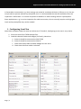
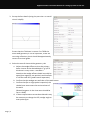
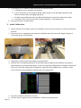
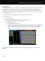
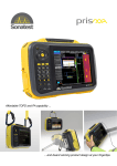
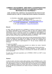
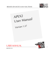
Application Note: Recommendations for setting up TOFD on the veo.
Application Note Title:
Author:
Recommendations for setting up TOFD on the veo
Joe Buckley, Sonatest Ltd.
Date:
Feb 28th, 2011.
Selection of Probe / Configuration
Easiest guide is CEN-TS14571
Thickness
t / mm
Number of
TOFD set-ups
Depth Range
Δt / mm
Centrefrequency
f/MHz
Beam Angle
(Long.waves)
Elementsize
/ mm
Beam
Intersection
6-10
1
0-t
15
70
2-3
2/3 of t
10-15
1
0-t
15-10
70
2-3
2/3 of t
15-35
1
0-t
10-5
70-60
2-6
2/3 of t
35-50
1
0-t
5-3
70-60
3-6
2/3 of t
50-100
2
0-t/2
t/2-t
5-3
5-3
70-60
60-45
3-6
6-12
1/3 of t
5/6 of t, or t
for 45°
100-200
3
0-t/3
t/3-2t/3
2t/3-t
5-3
5-3
5-2
70-60
60-45
60-45
3-6
6-12
6-20
2/9 ot t
5/9 of t
8/9 of t, or
t for 45°
200-300
4
0-t/4
t/4-t/2
t/2-3t/4
3t/4-t
5-3
5-3
5-2
3-1
70-60
60-45
60-45
40-50
3-6
6-12
6-20
10-20
1/12 of t
5/12 of t
8/12 of t
11/12 of t , or
t for ≤ 45°
Table 1: European Standard CSN-TS14741
Where possible the higher frequency should be used to improve measurement accuracy , but this will
require more gain and may not always be practical.
Note that the veo can support up to 2 pairs of TOFD probes, so Inspection of steel more than 100mm
thick will require two passes.
For thicknesses above this more specialised equipment or multiple scans should be used.
Page | 1
Application Note: Recommendations for setting up TOFD on the veo.
In favourable circumstances e.g. when testing new material, moderate thickness (<25mm or so) the veo
may be able to operate without a preamplifier, but it is recommended that one be available unless the
inspection is well known. It is normal to operate at 90 dB or so when working without a preamplifier.
Some applications, e.g. in service inspection for weld root erosion, do not normally require such high gain
levels and a preamplifier may not be needed.
1. Configuring Scan Plan
Note these examples show the work carried out on UT-Studio 3, Configuring on the veo is very similar.
1. Start with one of the TOFD example files
2. Load the selected Probes and wedges (2 of each), Note that:
a. Probe 1 should be connected to ChA TX/RX
b. Probe 2 should be connected to ChA Rx
c. Check that both probes and both wedges are the same
d. Check that LW wave mode is selected
Page | 2
Application Note: Recommendations for setting up TOFD on the veo.
3. Set up the Part details (using the part view or overall
view is helpful)
Ensure that the Thickness is correct. For TOFD the
exact weld geometry is not so important, as we are
not using reflections, but it should be approximately
correct as a visual guide.
4. Select the overall view and the geometry tab
a. Adjust the wedge Offsets so that the primary
beam insects at the desired depth. E.g. 2/3 of
thickness in many cases – see table 1.
Note that the wedge offsets should normally be
equal (one negative, one positive) and that each
is half the total PCS (probe centre separation)
b. Confirm that the wedges are well clear of the weld crown.
c. Confirm that (for a single probe inspection) the
shaded scan area covers the entire volume of
the weld
(Beam divergence in the view menu should be
set to -12dB)
d. If these requirements cannot be achieved it may
be necessary to change the PCS, wedge angle or
even probe type.
Page | 3
Application Note: Recommendations for setting up TOFD on the veo.
5. If setting up on UT-Studio for later use on a veo check also that
a. In Inspection menu Voltage is set to 200V
b. In scan menu Gain is set to approx 90 dB , Wave mode to LW, PRF approximately 2 kHz,
Filter to match probe, Averaging typically 4.
c. Set Ruler Lateral Wave Position and Back wall position to match the theoretical values.
d. In encoder menu set (if known) the encoder resolution. Scan distance etc.
6. Save the file with a suitable name.
2. Initial Calibration.
1. Adjust Scanner PCS to match value set in Software. Ensure that the scanner is securely clamped in
position.
2. Set up scanner on a good piece of material, if possible away from the weld. Apply couplant or
start water pump as appropriate
3. Adjust gain so that Lateral wave signal is at approx 60%.
4. Confirm that the displayed positions of the lateral wave and Back wall reflection correspond
approximately to the calculated values , If there are significant differences investigate. Note a few
mm error in the PCS makes quite a difference. Adjust the LW and BW rulers to match. Small
errors can be accommodated by adjusting the ruler LW position.
5. Check the encoder Calibration is correct
6. Confirm that the signal to noise is adequate , EN583 recommends that
Page | 4
Application Note: Recommendations for setting up TOFD on the veo.
a. Check that the noise before the lateral wave signal is at least 6dB less than the noise after it,
i.e. the electronic noise is not significant compare to the material noise.
b. A representative block (reference diffractors) should be used to verify sufficient signal to
noise ratio
3. While Scanning
Detailed recommendations are outside the scope of this, veo specific hints
F3 button is a quick shortcut to the ‘reset encoder position.
For later analysis you need to be recording data, refer to the veo user manual or quick start guide
4. Measurement settings
The Hyperbolic cursors can be useful for quick measurements while scanning. Useful when scanning
Select H1 Scan position and depth, H2 Scan position and depth, H1-H2 Distance, D1-H2 Depth
In Preferences turn on “Keep Measurement Bar”. This will show Measurement values, rather the list of
settings tabs.
Page | 5
Application Note: Recommendations for setting up TOFD on the veo.
Straightening.
The veo provides the facility to ‘straighten’ or align the lateral wave at a consistent point. This is very useful
to allow reliable measurements to be taken. The Threshold and window used for straightening can be
adjusted so that the straightening can be carried out without incorrect application to situations where the
lateral wave is ‘correctly’ disturbed, for example by surface breaking cracks. The same facility is provided in
the UT studio software.
Note that lateral wave straightening can only be carried out using recorded data.
To apply straightening:
1.
2.
3.
4.
Record the TOFD data.
In the scan menu ensure that the lateral wave position is correctly set.
In the Scan menu select straightening and turn it on.
In the straightening menu:
a. Check that ‘show indicators’ is on
b. Adjust LW Trig tolerance to a suitable value as shown by the colour band on the TOFD scan.
c. Adjust the LW trig Threshold to a suitable value as shown on the A-scan. The TOFD-scan will
easily show if some points drop below the threshold. This can be checked for validity as
above.
Interpretation of TOFD data is outside the scope of this note, Consult appropriate references such as
EN15617.
Page | 6