1
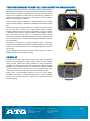
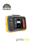
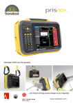
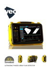
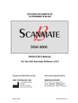
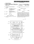
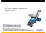
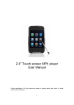
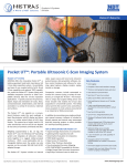
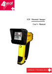
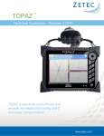
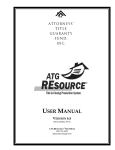
PRISMA SERIES UT Ultrasonic Phased Array Flaw Detector Series AS SIMPLE AS YOU WANT 30 second configuration single hand operation interactive help & 3D views configuration & calibration wizards “parameter genius” for additional guidance minimize training: common user interface AS CAPABLE AS YOU NEED UT, TOFD & PA inspection modes UT Studio - fast and dynamic reporting unique cursors for precision measurement recordability: screen shots, full data recording, fully traceable customized imaging layout.... over 25 to choose from STEP UP FROM CONVENTIONAL UT TO PHASED ARRAY Formats available are: Prisma UT Prisma UT + TOFD Prisma UT + PA Prisma UT + PA + TOFD upgradeable anytime, anywhere! UT TOFD ATG - Advanced Technology Group Beranovych 65 199 02 Prague 9 - Letnany Czech Republic PA E-mail: [email protected] Tel.: +420 273 037 611 Fax: +420 273 037 600 www.atg.cz 1/6 TRUE PERFORMANCE TO MEET ALL YOUR INSPECTION REQUIREMENTS The prisma is the latest product from Sonatest’s technician focussed product development and research. An advanced ultrasonic flaw detector offering the technician an extremely comprehensive tool for test and measurement, which can be upgraded to include TOFD and Phased Array capability. An upgrade can be carried out wherever you are, there is no need to return the instrument, eliminating any downtime. Simple controls, superior performance, advanced features and a rugged enclosure deliver simplicity, capability and reliability to the technician’s finger tips. With the best display size and resolution in it’s category, the prisma provides the end user with an intuitive and workflow driven interface, excellent imaging capability uses the Full screen mode allowing 100% of the display to be used for Scan Imaging. Numerous palettes are accessible for all scan types “see things how you want to”, in amplitude or depth C-Scans, customise your palettes. Take full advantage of the advanced display modes which include smoothing, contouring and averaging all available to enhance your signal quality. The prisma is constructed to exacting standards using a rigid, shock mounted, internal chassis surrounded by an impact absorbing enclosure and sealed to IP66; which ensures the unit is fully sealed against fine dust and jets of water. Typical applications are broad but include Weld Inspection, Corrosion Mapping, Aerospace and Composite Testing. PRISMA UT The Prisma UT model is fully loaded, carrying all the basic and advanced features of the Sonatest flaw detector range. Prisma UT offers damping control to either optimize near surface resolution or energy transmission. The ability to capture screens is standard combined with automatic reporting capability which enables reports to be formatted with relative bespoke customer information such as logos etc. The most popular flaw sizing techniques such as DAC, AVG/ DGS, TGC and AWS are all on-board. Thanks to the on-board software enhancing the B and C-Scan imaging capabilities, the Prisma UT enables field technicians to conduct dedicated corrosion and composite inspections, together with comprehensive on-site thickness profiling. ATG - Advanced Technology Group Beranovych 65 199 02 Prague 9 - Letnany Czech Republic E-mail: [email protected] Tel.: +420 273 037 611 Fax: +420 273 037 600 www.atg.cz 2/6 PRISMA TOFD Ultrasonic Time of Flight Diffraction (TOFD) has gained in popularity over the last decade and via the Prisma TOFD, Sonatest brings to the market a truly portable and powerful TOFD unit. Knowing that TOFD inspection can be carried out on wall thickness as thin as 6mm (1/4”), the Prisma offers the best digitizing frequency of its category going up to 200MHz. Simply put this means that high frequency transducers can be used, ensuring the most accurate flaw height sizing possible. TOFD is a versatile technique; with two UT channels the Prisma permits the inspection of thick component in a single pass. This is enhanced by the high voltage square wave pulsers delivering up to 450V. Prisma TOFD offers the complete hardware configuration to deliver the best performance, but it would be incomplete without the on-board software features such as hyperbolic cursors, lateral wave straightening and lateral wave removal. S, True Top, Side and End view extractions, together with C-Scans, are all supported. PRISMA PA Ultrasonic Phased Array technology has become the established method for advanced NDT testing applications. Phased Array Techniques allow the user to cover a wider volume of inspection; such as being able to cover the complete span of a weld without the need to move or reposition the transducer. This is possible due to phased array enabling beams to be electronically steered. This technique results in comprehensive imaging of the results showing a quasi cross section of the inspected part. With the Prisma PA you can switch easily and quickly between the UT and PA operating modes with a simple press of a button, no data or time is lost. The Inspection Plan shows the operator in 2D and 3D where probes are positioned on the test part, simplifying the inspection set up and providing an inspection reference for reporting. All adjustments to focal laws are instantaneous. Multiple sectorial scans, true top,side and end view extractions, together with C-Scans, are all supported. UT STUDIO UT Studio is a PC based software, which accompanies the Prisma and enables powerful post analysis capability. Not only does it offer excellent report generation features but new views can be generated and comparative analysis can be conducted by opening multiple inspection data files, re-gating and producing fully illustrated reports. Working in a familiar “drag and drop” environment the end user can create multiple views such a Top, End and BScan visual files by simply dragging Prisma data files onto templates for presentations. Full recordability of data when using the Prisma is standard, which means that screenshots and all data can be retained and analyzed at a later date using UT Studio. IN using the full data gathering capability traceability can be achieved; hence repeatability of the inspection and results can be confirmed. Powerful measurement cursors and extractors can be added to identify indications, size and annotate defects. Reports are easily generated and can be exported into PDF format for review and circulation. Free downloads of UT Studio Viewer are available for the technician’s client to use. ATG - Advanced Technology Group Beranovych 65 199 02 Prague 9 - Letnany Czech Republic E-mail: [email protected] Tel.: +420 273 037 611 Fax: +420 273 037 600 www.atg.cz 3/6 SPECIFICATION Conventional UT Phased Array PULSERS Configuration 2 UT channels 16:16 or 16:64 Test Mode Pulse-Echo, transmit/receive and TOFD Pulse-Echo, transmit/receive Transducer Socket LEMO 1 or BNC I-PEX Pulse Voltage -100 V to -450 V (in steps of 10 V) -25 V to - 75 V (in steps of 5 V) Pulser pulse width adjustable from spike to 2000ns (2.5ns resolution) pulse width adjustable spike to 1000ns (2.5ns resolution) PRF 3 Hz to 5 kHz 3 Hz to 5 kHz Pulse Shape negative square wave (with ActiveEdge) negative square wave (with ActiveEdge) Pulse Width adjustable: 25ns to 2000ns (2.5 ns resolution) adjustable: 25ns to 1000ns (2.5 ns resolution) Edge Time 15 ns in 50 Ω load @200 V 12 ns in 50 Ω load @50 V Output Impedance 5Ω <10 Ω Synchronisation encoder or free-running (time based) encoder or free-running (time based) Focus Delay Range n/a 0 to 10 µs (2.5 ns resolution) Damping Resistor selectable: 50 Ω or 400 Ω n/a Gain Range 120 dB (-40 dB to 80 dB), Analogue Gain 0 to 80 dB (0.1 dB steps), Analogue Gain Max Input Voltage 25 Vp-p 200 mVp-p Input Impedance 1 kΩ (pitch and catch) 200 Ω Bandwidth 200 kHz to 22 MHz (-3 dB) 200 kHz to 14 MHz Analog Filters 4 3 Digital Filters 10 10 Rectification full wave, positive, negative, none (RF) full wave, positive, negative, none (RF) Single Enhancement digital filters, averaging, smoothing, contouring digital filters, smoothing Focus Delay Range n/a 0 to 10ns (16 ns resolution interpolated to 3.8 ns) Architecture 2 channels, true 200 MHz sampling rate 16 channels, full digital delay & sum Digitizer Resolution 12 bit ADC 12 bit ADC Amplitude Measurement [0% to 100%] or [0% to 150%] FSH [0% to 100%] or [0% to 150%] FSH Data Processing 16 bits/sample 16 bits/sample Data Recording full raw data recording full raw data recording File Size up to 3 GB up to 3 GB Digitizing Frequency 50 MHz, 100 MHz, 200 MHz 65 MHz Focal Laws n/a 128 Focussing Type n/a constant depth, constant path, constant offset Max A-Scan Length 8192 samples 4096 samples Sub-Sampling 1:1 to 1:128 1:1 to 1:128 Reference initial pulse or Gate/IFT supported Initial Pulse or Gate/IFT supported Trigger Sync. encoder or Internal encoder or Internal Supported Scans A-Scan & TOFD S-Scan or L-Scan Number of Scans up to 4 1 (with up to 4 extracted A-Scans) Views A, B, C-Scan plus TOFD A, B, C, L, S-Scan plus End & Top view Colour Maps up to 10 up to 10 Number of Layouts 12 17 Cursor Types cartesian, hyperbolic (TOFD) cartesian, extraction box, angular Measurements path length, depth, surface distance, DAC, AWS, DGS path length, depth, surface distance, DAC, AWS RECEIVERS DATA ACQUISITION SCAN & VIEWS CURSORS ATG - Advanced Technology Group Beranovych 65 199 02 Prague 9 - Letnany Czech Republic E-mail: [email protected] Tel.: +420 273 037 611 Fax: +420 273 037 600 www.atg.cz 4/6 Conventional UT Phased Array DAC & TCG DAC points 16 16 DAC 1 with 3 “sub DACs” 1 with 3 “sub DACs” per focal Law TCG points 16 16 Gain Range 60 dB 40 dB Max Gain Slope 60 dB/µs 50 dB/µs A-Scan Gates 4 gates per A-Scan 4 gates per A-Scan (3 extracted A-Scans per S/L-Scan) Gate Trigger flank/peak flank/peak S/L-Scan n/a 1 Extraction Box Alarm LED 1 (sync on all gates & DACs) 1 (sync on all gates & DACs) Measurements (A-Scan) peak & flank (FSH, dB, D, BPL, SD) and Echo-to-Echo peak & flank (FSH, dB, D, BPL, SD) and Echo-to-Echo GATES INTERFACE & REPORTING Help System active parameter description and optimization tips Configuration Validation dynamic help with parameter genius Wizards configuration, velocity and zero, wedge delay, sensitivity, TCG, DAC, DGS, element activation, encoder Languages (dynamic) English, German, French, Spanish, Russian, Chinese Report Generation PDF File (includes scans, setup, measurements, etc.), PNG screen capture, customer Logo PDF Reader allows viewing any uploaded PDF file INPUTS & OUTPUTS Encoder 1 or 2 axis encoding (quadrature input) Digital Inputs 2 input lines (5V TTL) Digital Outputs 2 output lines (5V TTL, 20 mA) for alarm or other external control Analogue Outputs 2 analogue output lines (0-2V) Power Output 5V, 350 mA, current limited ENCLOSURE Dimensions (HxWxD) 205mm x 300mm x 90 mm Weight 3.5 kg (with battery) Display Size 8.4 inch (diagonal) Display Resolution 800 x 600 Display Colours 260k (65535 colours for scan palettes) Display Type TFT LCD, 450 Cd/m2, with 2% reflectivity USB ports 3 USB master ports Ethernet 100 Mbps BATTERY & POWER SUPPLY Battery Type intelligent Li-ion Number of batteries 1 Operation on battery or on external power (DC Power Pack) Battery Replacement yes, no tools required Battery Recharge recharge in unit (with unit On or OFF) - external battery charger (std) Battery Life typical: 7 hours in UT mode, 6 hours in PA mode ENVIRONMENTAL IP Rating designed to meet IP66 Operating Temperature -10 °C to 45 °C (14 °F to 113 °F) Storage Temperature -25 °C to 60 °C (-13 °F to 140 °F) ATG - Advanced Technology Group Beranovych 65 199 02 Prague 9 - Letnany Czech Republic E-mail: [email protected] Tel.: +420 273 037 611 Fax: +420 273 037 600 www.atg.cz 5/6 PRISMA UT STANDARD KIT Dual UT Channels with: A-Scan Recording 2 Axis Encoding Interface Triggering (IFT) A,B and C scan displays USB Stick (8GB) couplant user manual/ quick user guide 2 point neck harness lithium-Ion battery packs (x2) external battery charger power cord & power supply adaptor screen protector (anti-glare) transport case (airplane carry on size) PRISMA UT/PA 16/16 STANDARD KIT Dual UT channel kit above plus 16:16, manual PA OPTIONS UT option TOFD *encoding for UT is standard *IFT for UT is standard PA option 16:64 2 axis encoding & recording for PA IFT for PA encoder Y-Splitter ATG - Advanced Technology Group Beranovych 65 199 02 Prague 9 - Letnany Czech Republic E-mail: [email protected] Tel.: +420 273 037 611 Fax: +420 273 037 600 www.atg.cz 6/6