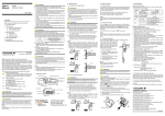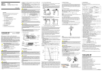
1
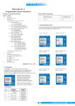
Contents User’s Manual CL360 Leakage Clamp-on Tester リーククランプテスタ Precautions for Safety Use of the Instrument --------------------------- i 1. Instrument Layout ------------------------------------------------------------ 1 2. Measurement ------------------------------------------------------------------ 3 2.1 2.2 2.3 2.4 2.5 2.6 2.7 IM CL360 99 Washington Street Melrose, MA 02176 Fax 781-665-0780 TestEquipmentDepot.com Preparation for Measurement ------------------------------------------------ 3 AC Current Measurement ----------------------------------------------------- 3 How to Use The Frequency Selector Switch ----------------------------- 4 How to Use Peak Hold Function--------------------------------------------- 5 How to Use Peak Hold Frequency Selector Switch -------------------- 7 How to Use Data Hold Function ------------------------------------------- 10 How to Use OUTPUT Terminal -------------------------------------------- 10 3. Battery Replacement ------------------------------------------------------ 11 4. Specifications ---------------------------------------------------------------- 12 5. Calibration and After-sales Service ------------------------------------ 15 IM CL360 2003.06 2 版(MC) Precautions for Safe Use of the Instrument When handling the instrument, ALWAYS observe all of the cautionary notes on safety given below. Yokogawa M&C Corporation is not at all liable for damage resulting from misuse of this product by the user that is contrary to these cautionary notes. Various symbols are used on the instrument and in this manual to ensure the product is used safety and to protect operators and property from possible hazards or damage. The following safety symbols are used where appropriate. Read the explanations carefully and familiarize yourself with the symbols before reading the text. The instrument and this manual use the following safety symbols: Danger! Handle with Care. This symbol indicates that the operator must refer to an explanation in the User’s Manual in order to avoid the risk of personal injury or death and/or damage to the instrument. Double Insulation This symbol indicates double insulation. WARNING ● Never make measurement on a circuit above 600V AC. ● Do not use the instrument in an atmosphere where any flammable or explosive gas is present. ● Do not attempt to make measurement in the presence of flammable gasses, fumes, vapor or dust. Otherwise, the use of the instrument may cause sparking, which can lead to an explosion. ● Avoid using the instrument if it has been exposed to rain or moisture or if your hands are wet. ● Do not exceed the maximum allowabIe input of any measurement range. ● Never open the battery compartment cover when making measurement. ● Do not use the instrument if there is any damage to the casing or when the casing is removed. ● Do not install substitute parts or make any modification to the instrument. Return the instrument to Yokogawa M&C or your distributor for repair or re-calibration. ● Always switch off the instrument before opening the battery compartment cover for battery replacement. AC Voltage/Current This symbol indicates AC voltage or current. WARNING Ground This symbol indicates ground (earth) To avoid damage to the instrument or electric shock! The restrictions on the maximum voltage level for which the CL360 testers can be used, depend on the over-voltage categories specified by the safety standards. These category specifications are formulated to protect operators against transient impulse voltage in power lines. WARNING Indicates that there is a possibility of serious personal injury or loss of life if the operating procedure is not followed correctly and describes the precautions for avoiding such injury or loss of life. Function CAUTION A Indicates that there is a possibility of serious personal injury of damage to the instrument if the operating procedure is not followed correctly and describes the precautions for avoiding such injury or damage. Maximum Allowable Input OVERVOLTAGE OVERVOLTAGE CATEGORY II CATEGORY III AC 1000A rms Measuring circuit voltage : AC 600V rms AC 1000A rms Measuring circuit voltage : AC 300V rms Over-voltage category I (CAT.I): Signal level, special equipment or parts of equipment, telecommunication, electronic etc., with smaller transient over-voltages than CAT.II. NOTE Draws attention to information essential for understanding the operation and features. Over-voltage category II (CAT.II) Local level, appliance, portable equipment etc., with smaller transient over-voltages than CAT.III. Over-voltage category III (CAT.III): Distribution level, fixed installation, with smaller transient over-voltages than CAT.IV. IM CL360 i ii IM CL360 CAUTION ● Be sure to set the Range switch to the "OFF" position after use. When the instrument will not be in use for a long period of time, place it in storage after removing the battery. ● Do not expose the instrument to the direct sun, extreme temperatures or dew fall. ● Never apply voltage to the OUTPUT terminal. The terminal is not electrically isolated from the internal circuits of the instrument. ● Use a damp cloth and detergent for cleaning the instrument. Do not use abrasives or solvents. NOTE ● Radiation immunity affects the accuracy of CL360 testers under the conditions specified in EN 61000-4-3:1997. ● If equipment generating strong electromagnetic interference is located nearly, the testers may malfunction. IM CL360 iii 1. Instrument Layout (3) Two-way Analogue OUTPUT Terminal : AC current picked up by transformer jaws (7) is converted and output as AC and DC voltage output. (See Analogue Output in chapter 4. Specifications) Insert output cord Model 91020 into this terminal for monitoring waveform with an oscilloscope, making RMS measurements or connecting to a recorder. (4) Safety Hand Strap : Prevents the instrument from slipping off the hand during use. (5) Range Switch : Selects range. It is also used to turn power on or off. (6) Open/Close Lever : Operates the transformer jaws. Press to open the transformer Jaws. (7) Transformer Jaws : Pick up current flowing through the conductor. (8) Peak Hold Selector Switch : Selects 10ms or 100ms response time. Set the switch back to the OFF position to release peak hold or make normal measurements. (9) Frequency Selector Switch : Makes frequency response selection. Selects "WIDE" or "50/60Hz". (7) (6) (1) OFF (2) (9) (5) (8) (4) (3) (1) LCD Display : Field effect type of liquid crystal display with maximum counts of 1999. Range symbol (mA, A) and decimal point automatically appear as the Range switch is turned. "B" is displayed on the lower left corner for low battery warning and "1" is displayed only at the higher digit for overrange indication (except for 1000A range). (2) Data Hold Button : Allows for easy reading in dimly lit or hard-to-reach locations. The display can be observed away from the conductor after pushing in the button. 1 IM CL360 2. Measurement 2 IM CL360 (3) To measure out of balance leakage current, clamp onto all conductors except a grounded wire. The leakage current measured will be indicated on the display. 2.1 Preparation for Measurement CAUTION 3-phase system ● The jaw section is a delicate, precision sensor. Do not subject the jaw to unreasonably strong shock, vibration, or force when using it. ● If dust gets into the tops of the jaws, remove it immediately. Do not close the jaws when dust is trapped in its joints as the sensor may break. ● Please check that the range is set to the desired setting before measurement. Load Load In case of 1-phase 3-wire system, In case of 3-phase 4-wire system, clam four wires for measurement. clamp three wires for measurement. 2.2 AC Current Measurement WARNING CAUTION When measuring large current, observe the time limit specified in chapter 4, Specifications. Otherwise, the transformers jaws may overheat, resulting in damage to the instrument. Do not make measurement on a circuit above 600V AC. This may cause shock hazard or damage to the instrument or equipment under test. (1) Set the range switch to the desired position. Do not exceed the maximum allowable input current for the selected range. (2) For normal measurement, press the open/close lever to open the transformer jaws and clamp onto one conductor only. Earth leakage current or small current that flow through a grounded wire can also be measured by this method. It is recommended that the conductor is placed at the center of the closed transformer jaws. Correct NOTE ● During current measurement, keep the transformer jaws fully closed. Otherwise, accurate measurement cannot be made. The maximum measurable conductor size is approx. 68mm in diameter. ● Frequency selector switch is designed to select the "50/60Hz " and "WIDE" frequency ranges. For further details, refer to section 2.3 for operation of frequency selector switch. ● The transformer jaws may buzz when measuring large current. This has no effect on the instrument’s performance or safety. 2.3 How to Use The Frequency Selector Switch Wrong Model CL360 has a very good frequency response because of the electromagnetic property of its transformer jaws. Therefore, it measures AC current not only of fundamental frequency of 50Hz or 60Hz, but of high frequencies and harmonics superimposed on the fundamental frequency. To eliminate these superimposed components and measure only in the fundamental frequency, Model CL360 has a high-cut filter circuit, which can be activated by setting the frequency selector switch to the 50/60Hz position. The high-cut filter has a cut-off frequency of approx. 100Hz and an attenuation characteristics of approx. -24dB/octave. NOTE -24dB/octave means that the magnitude of a signal declines by a factor of 16 when its initial frequency doubles. IM CL360 3 4 IM CL360 The frequency selector switch has the following two positions. ● WIDE (40Hz to over 1kHz) : Covers a wide frequency band from mains supply to high frequencies generated by such equipment as inverters. ● 50/60Hz (40 to Approx. 100Hz) : Filters out high frequency components to restrict measurement in mains frequency band. NOTE Selection with the frequency selector switch does not apply to AC output of the two-way analogue output. 2.4 How to Use Peak Hold Function 10ms or 100ms response time can be selected for peak hold measurement. Make selection according to your application needs. (1) With the transformer jaws clamped onto the conductor under test, slide the peak hold switch from the OFF position to the desired peak response time position. (2) The peak hold display reads 1/ 2 of the peak current value. Therefore, an RMS reading will be obtained when the current under test has a sinusoidal waveform. Input Current IP NOTE ● Model CL360 uses an analogue peak hold circuit to ensure a quick response to input current. Because of the nature of this circuit, the peak hold reading may gradually fall, or in a rare case, rise with time. This is likely to be apparent when the instrument is used in a high temperature and high humidity environment. Therefore, the instrument will not be suitable for making peak measurement over an extended period of time. In case of such a need, connect a recorder to the instrument via the analogue output terminal. ● If it is necessary to read the display away from the conductor in a peak hold measurement, press the data hold switch first and then remove the instrument from the conductor. Otherwise, the peak hold reading may be higher than the actual value due to the electrical noise caused by the opening and closing of the transformer jaws. Press the data hold switch again for a reset. (4) Difference between 10ms and 100ms Peak Response Time. The peak hold circuit in this instrument charges the peak-hold capacitor after rectifying the input waveform. The time for the voltage of the capacitor to reach its peak value varies according to its capacitance and the output impedance of the charging circuit. Model CL360 sets the time for the voltage of the capacitor to reach 90% of its peak value to 10ms or 100ms by switching between two output impedances. 10ms Peak Response Time 100ms Peak Response Time Input Waveform Peak Hold Current Output (display value & DC output) IP Hold Capacitor Voltage 100% 90% 100% 90% (3) Slide the peak hold switch back to the OFF position for a reset. 10ms t 100ms t For instance, select the 10ms response time when measuring a surge current that will occur when a power supply device is switched on. The 100ms response time is recommended for measuring the starting current of a motor or similar equipment. A stable measurement can be made on the 100ms second response time setting as the peak hold circuit does not readily respond to the surge current. 5 IM CL360 2.5 How to Use Peak Hold Frequency Selector Switch 6 IM CL360 Example 1 When measuring the peak of starting current of motor: Indicated value may vary according on input signal (waveform) when the frequency selector switch is set to 50/60Hz. In this case, make measurement referring to the block diagram below. (1) Input waveform (I-V circuit output) Circuit flowchart is shown below. Display circuit Voltage divider (100ms or 10ms) ( (1) (2) (3) (3) Peak hold circuit (Hold value) Frequency Selector Wave at WIDE position (OFF) Peak hold circuit Peak hold Selection switch (50/60Hz) Rectifying circuit SW (WIDE) High cut Filter Conversion CT Frequency selection I-V (2) Rectifying circuit input Surge pulse at switching on (switching noise) 1 ) 2 The signal (current) picked up by transformer jaws is converted from current signal to voltage signal in I-V conversion circuit, and it enters the frequency selector switch. If the frequency selector switch is set to WIED, it enters the rectifying circuit. If set to 50/60Hz, enters the rectifying circuit after passing through high-cut filter (cut-off frequency of approx. 100Hz and attenuation characteristics of approx. -24dB/octave). If the peak hold selector switch is set to OFF, the rectified signal enters the indication circuit. If set to 100ms or 10ms, passes through the peak hold circuit, picks up the peak value of input signal, and outputs 1/ 2 of the peak value into the indication circuit. Different examples of peak hold statuses when the frequency selector switch is set to WIDE or 50/60Hz are described below. Frequency Selector Wave at 50/60Hz position Waveform after passing through high-cut filter Example 2 When measuring the peak current of thyristor: (1) Input waveform (I-V circuit output) NOTE (2) Rectifying circuit input (3) Peak hold circuit (Hold value) Frequency Selector Wave at WIDE position If the frequency selector switch is switched after the peak hold switch is set to 100ms or 10ms, the over indication appears. Make sure that first set the frequency selector switch, then, set the peak hold switch to 100ms or 10ms. Frequency Selector Wave at 50/60Hz position Waveform after passing through high-cut filter IM CL360 7 8 IM CL360 Example 3 When measuring the peak current of inverter (where harmonic are superimposed on the fundamental frequency): (1) Input waveform (I-V circuit output) (2) Rectifying circuit input (3) Peak hold circuit (Hold value) 2.6 How to Use Data Hold Function Push in the Data Hold button to freeze the reading. This is especially useful for taking a reading a dimly lit or hard-to-reach locations. The display can be observed away from the conductor. Push the button again to release the reading. 2.7 How to Use OUTPUT terminal Frequency Selector Wave at WIDE position AC and DC outputs can be obtained by inserting optional Model 91020 output cord into the two-way analogue output terminal. AC Output : Can be monitored by connecting a digital multimeter to analogue output terminal or observed as waveform by connecting an oscilloscope. DC Output : Can be monitored by connecting a digital multimeter, or a recorder, which enables many hours of monitoring. With the CL360 in the peak hold mode, DC voltage corresponding to 1/ 2 of a peak current value can be held and outputted. Frequency Selector Wave at 50/60Hz position Waveform after passing through high-cut filter NOTE Model 91020 (optional) Black(COM) The indicated value at 50/60Hz may be higher than that at WIDE because of the phase difference between superimposed harmonics and fundamental frequency. Red(DC) CAP OFF Blue(AC) Note : Put a cap on the plug when not in use. Model CL360 Connect to multimeter or recorder (connect to oscilloscope or multimeter) AC output AC output Oscilloscope 9 IM CL360 3. Battery Replacement DC output DC output Recorder Multimeter 10 IM CL360 4. Specifications Instrument Specifications WARNING To avoid electric shock hazard, make sure to set the Range switch to "OFF" and remove the test leads from the instrument before trying to replace battery. ● Measuring Ranges and Accuracy (at 23 ±10°C, 85% relative humidity or less) AC Current Ranges CAUTIOIN A Measuring range Accuracy Frequency WIDE 200mA 0 to 199.9mA ±1.0% rdg ±2dgt (50/60Hz) 2A 0 to 1.999A ±3.0% rdg ±2dgt 20A 0 to 19.99A (40 to 1kHz) Make sure to install battery in correct polarity as indicated in battery compartment. ±1.5% rdg ±2dgt (50/60Hz) ±3.5% rdg± 2dgt (40 to 1kHz) ±1.5% rdg ±2dgt (50/60Hz) 0 to 500A ±3.5% rdg ±2dgt 1000A (40 to 1kHz) ±5% rdg (50/60Hz) 501 to 1000A ±10% rdg (40 to 1kHz) Replace the battery when "B" symbol appears on the LCD display. 200A (1) Set the Range switch to the "OFF" position. (2) Unscrew and remove the battery compartment on the bottom of the instrument. (3) Replace the battery observing correct polarity. Use a new 6F22 or 6LR61 battery. (4) Re-place and screw the battery compartment cover. 0 to 199.9A 50/60Hz Time limit for Measurements ±1.5% rdg ±2dgt ±2.0% rdg ±2dgt Continuous ±2.0% rdg ±2dgt ±5.5% rdg 10min. Attenuation (dB) 1000A range Typical frequency characteristics for 2A and higher ranges with the frequency selector switch at WIDE position. Typical characteristics for 200mA range with the frequency selector switch at WIDE position. All ranges With the frequency selector switch set at 50/60Hz position to cut off higher frequencies -24dB/oct Errors as aginst reading at 50Hz (%) 6F22 Battery Remove this screw Frequency (Hz) IM CL360 11 12 IM CL360 Analogue Output (Output impedance: Approx. 1kΩ) AC Output Range Measuring range 200mA ● Storage Temperature and Humidity : -10 to 50°C, relative humidity up to 80% without condensation ● Effect of conductor position: Within 2% difference between maximum and minimum values to a 10 mm-dia conductor, at every part inside the jaws Accuracy AC Output Voltage 0 to 200mA 2A 0 to 2A 20A 0 to 20A 200A 0 to 200A 0 to 200mV 0 to 500A 0 to 50mV ±2.0% rdg ● Effect of External Magnetic Field : 15mA AC max. in proximity to a 10mm-dia conductor carrying 100A AC. ±2.5% rdg ● Effect of Residual Current : 10mA AC max. when clamping on two 10mm-dia conductors, each carrying supply or return 100A AC current. ±3.0% rdg 1000A 501 to 1000A 50 to 100mV ±5.0% rdg Voltage proportional to the current under test is output with “WIDE” frequency characteristics regardless of the setting of the frequency selector or peak hold switch. ● Power Source : 6LR61 or 6F22 DC9V battery ● Battery Life : Approx. 60 hours (continuity) ● Current Consumption : Approx. 5mA max. DC Output ● Withstanding Voltage : 3700V AC, 50/60Hz for 1 minute between electrical circuit and housing case or metal part of the jaws Accuracy (Frequency Range) Range 200mA 0 to 200mA 2A 0 to 2A 20A 0 to 20A 200A 0 to 200A 1000A DC Output Voltage Measuring range 0 to 200mV Freq. Selector Switch at WIDE position Freq. Selector Switch at 50/60Hz position ±3.0% rdg ±3.5% rdg ±3.5% rdg ±4.0% rdg 0 to 500A 0 to 50mV ±5.0% rdg ±5.5% rdg 501 to 1000A 50 to 100mV ±7.0% rdg ±7.5% rdg ● Insulation Resistance : 10MΩ or greater at 1000V between electrical circuit and housing case or metal part of the jaws ● Conductor Size : Approx. 68mm diameter max. ● Dimensions : Approx.130(W) x 250(H) x 50(D) mm ● Weight : Approx. 570g ● Safety Standard: EN 61010-1 EN 61010-2-032 AC 300V CAT III, AC 600V CAT II, Pollution degree 2, indoor use General Specifications ● Operating System : Dual integration ● EMC Standard: EN 61326 EN 55022 ● Measurement Function : AC current ● Accessories : 6F22 battery······························ 1 Carrying case Model 93031 ······ 1 ● Display : Field effect 3 - 1/2 digit liquid crystal display with maximum count of 1999 User’s Manual ··························· 1 ● Range selection : Manual ● Optional Accessories : Output cable with banana plug Model 91020 ● Overrange Indication : "1" is displayed on the highest digit except for 1000A AC range. ● Peak Hold : Response time selectable from approx. 10ms and 100ms. 1/ 2 of the peak current is displayed, which means an RMS reading will be obtained when current having sinusoidal waveform in measured. Peak hold reading varies by approximately ±1% max of full scale in the first minute at 23°C ±10°C and relative humidity of 75% without condensation. ● Response Time : Approx. 1 seconds. ● Sample Rate : Approx. 3 times per second. ● Temperature and Humidity for Guaranteed Accuracy : 23°C ±10°C, relative humidity up to 85% without condensation ● Operating Temperature and Humidity : 0 to 40°C, relative humidity up to 85% without condensation 13 IM CL360 14 5. Calibration and After-sales Service Should any failure occur while you are using the tester, follow the instructions given below. If the tester still fails to operate correctly and needs repair, contact the vendor from whom you purchased the instrument or the nearest Yokogawa M&C sales office. Condition Display blanks after power-on Display reading remains frozen. Transformer jaws buzz when measuring large current. The lowest digit of reading is unstable Possible Cause Battery is improperly installed. Battery is exhausted. Data hold button is pressed in. Peak hold switch is at ON position. Remedy Install the battery correctly. Replace the buttery. Release data hold button. Set peak hold switch to OFF position. This is not a failure ----------------- ----------------- Output cable The cable is open circuit. (Model 91020) does not output voltage. This is not a failure. The instrument is highly accurate, so it senses slight variations in the current under test. Check the cable for an open circuit. Calibration It is recommended that the instrument be calibrated once every year. Test Equipment Depot - 800.517.8431 - 99 Washington Street Melrose, MA 02176 FAX 781.665.0780 - TestEquipmentDepot.com IM CL360 15 IM CL360