1
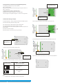
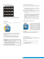
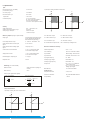
ZIEGLER PRO-I
ZIEGLER PRO -I
Programmable Current Transducer
Table 1: Measured parameters
Installation & Operating Instructions
Section
Contents
1.
Introduction
Measured parameters
Unit of Measurement
2.
3.
Input and Output screens
Programming
Current
Amp
3.1 Programming via Front LCD & Two keys
3.1.1 Password Protection
3.1.1.1 Password verification
3.1.1.2 New / Change Password
3.1.2 Current Transformer parameter selection
3.1.2.1 Current Transformer primary value
3.1.2.2 Current Transformer secondary value
3.1.3 Communication Parameter selection
3.1.3.1 Address Setting
3.1.3.2 RS 485 Baud rate
3.1.3.3 RS 485 Parity selection
3.1.4 Output Type selection
3.1.4.1 Output 1 Type selection
3.1.4.2 Output 2 Type selection
3.1.5 Input parameter selection
3.1.5.1 End value of input
3.1.5.2 Start value of input
3.1.5.3 Elbow Function Selection
3.1.5.4 Elbow value of input
3.1.6 Output parameter selection
3.1.6.1 Output 1 parameter selection
3.1.6.1.1 End value of output 1
3.1.6.1.2 Start value of output 1
3.1.6.1.3 Elbow value of output 1
3.1.6.2 Output 2 parameter selection
3.1.6.2.1 End value of output 2
3.1.6.2.2 Start value of output 2
3.1.6.2.3 Elbow value of output 2
2 . Input and Output screens
In normal operation the user is presented with display test screen followed by version screen
to one of the output screen. These screens may be scrolled through one at a time Output 1 or
Output 2 by pressing the “
Up key” or “
Down key”.
Screen 1 : Display Test
ON O/P1 O/P2
COM
Screen 2 : Version Screen
ON O/P1 O/P2
COM
INPUT x012
A
O/P 12 y012
A
Ziegler PRO -I
Ziegler PRO -I
3.2 Programming Via Programming port
Screen 3 : Current Input and
Screen 4 : Current Input and
4.
RS 485 ( ModBus )
Output 1 as Voltage
Output 1 as Current
5.
Installation
5.1 EMC Installation Requirements
5.2 Case Dimensions and Panel Cut-out
5.3 Wiring
5.4 Auxiliary Supply
5.5 Fusing
5.6 Earth / Ground Connections
Specification
Connection Diagrams
6.
7.
ON O/P1 O/P2
COM
ON O/P1 O/P2
COM
INPUT
INPUT
A
A
O/P 1
O/P 1
A
15030988_Rev.A - 10/11 - E1R0
Ziegler PRO -I
Ziegler PRO -I
1. Introduction
The Ziegler PRO - I is a panel mounted 43.5X 65.5mm Transducer.
The Ziegler PRO - I is used to measure and convert AC Current input into an
proportional DC current or voltage output signal. Output signal generated is
proportional to the True RMS(upto 15th Harmonic) of the input Current.
Input Current and Output Voltage/Current is displayed on LCD and indicated by LED’s.
Screen 5 : Current Input and
Screen 6 : Current Input and
Output 2 as Voltage
Output 2 as Current
ON O/P1 O/P2
ON O/P1 O/P2
COM
INPUT x012
A
O/P 12 y012
Ziegler PRO - I can be configured and
programmed at site for the following :
CT Primary ,CT Secondary (5A or1A) ,
Input parameters (i.e start, end and
elbow value of Input) and Output
parameters(i.e as Voltage or as Current
and start, end and elbow value of outputs).
COM
ON O/P1 O/P2
COM
INPUT
INPUT
A
A
O/P 2
O/P 2
A
A
Ziegler PRO -I
The front panel has two keys through
which the user may scroll through the
output screens and configure the product.
Ziegler PRO -I
Ziegler PRO -I
1.1 LED Indication
LED
ON
Led Operating
Condition
Aux. Supply healthy
condition
Output1 voltage
O/P 1
Output1 Current
Output2 voltage
O/P 2
Output2 Current
Led Operating
Status
Green LED
continuous ON
Green LED
continuous ON
Red LED
continuous ON
Green LED
continuous ON
Red LED
continuous ON
www.ziegler-instruments.com
1
|
16
3. Programming
Programming of transducer can be done in three ways :
1) Programming Via Front LCD & two keys.
ON O/P1 O/P2
COM
Password Incorrect.
This screen is displayed when the unit has not accepted
2) Programming Via optional RS485(MODBUS) communication port.
the Password entered.
Pressing the "
Down" key will re-enter to
the “Enter Password” entry stage.
3.1 Programming via Front LCD & Two keys
The following sections comprise step by step procedures for configuring the
Ziegler PRO - I for individual user requirements.
To access the set-up screens press and hold the “
Down” and “
Up”
keys simultaneously for 5 seconds. This will take the User into the Password
Protection Entry Stage .
3.1.1. Password Protection
Ziegler PRO -I
ON O/P1 O/P2
COM
New / Change Password
(*Denotes that digit will be flashing).
Password protection can be enabled to prevent unauthorised access to set-up
screens, by default password protection is not enabled.
Pressing the “
Down” key will scroll the value of the
first digit from 0 through to 9, the value will wrap from 9
round to 0.
*
Password protection is enabled by selecting a four digit number other than 0000,
setting a password of 0000 disables the password protection.
COM
Up” key will exit the
3.1.1.2 New/Change Password
3.1.1.1 Password Verification
ON O/P1 O/P2
Pressing the “
setup menu.
Enter Password, prompt for first digit.
(*Denotes that digit will be flashing).
Ziegler PRO -I
Pressing the “
Up” key will advance the operation to
the next digit and set the first digit, in this case to “4”
Pressing the “
Down” key will scroll the value of the first digit
from 0 through to 9, the value will wrap from 9 round to 0.
*
Pressing the “
Up” key will advance the operation to
the next digit and set the first digit.
Ziegler PRO -I
ON O/P1 O/P2
COM
In the special case where the Password is “0000” pressing
the “
Up” key when prompted for the first digit will
advance to the “Password Set/Confirmed” screen.
ON O/P1 O/P2
COM
Enter New / Change Password, first digit entered, prompting for
second digit. (*Denotes that digit will be flashing).
Pressing the “
Down” key will scroll the value of the
second digit from 0 through to 9, the value will wrap from
9 round to 0.
*
Enter Password, first digit entered, prompt for second digit.
(*Denotes that digit will be flashing).
Ziegler PRO -I
Pressing the “
Up” key will advance the operation to the
next digit and set the second digit, in this case to “1”
Pressing the “
Down” key will scroll the value of the second digit
from 0 through to 9, the value will wrap from 9 round to 0.
*
ON O/P1 O/P2
COM
Pressing the “
Up” key will advance the operation to the
next digit and set the second digit.
ON O/P1 O/P2
COM
Pressing the “
Down” key will scroll the value of the
third digit from 0 through to 9, the value will wrap from 9
round to 0.
*
Ziegler PRO -I
Enter Password, second digit entered, prompt for third digit.
(*Denotes that digit will be flashing).
Enter New / Change Password, second digit entered, prompting for
third digit. (*Denotes that digit will be flashing).
Ziegler PRO -I
Pressing the “
Up” key will advance the operation to
the next digit and set the third digit, in this case to “4”
Pressing the “
Down” key will scroll the value of the third digit
from 0 through to 9, the value will wrap from 9 round to 0.
*
ON O/P1 O/P2
COM
Pressing the “
Up” key will advance the operation to the
next digit and set the third digit.
Ziegler PRO -I
ON O/P1 O/P2
COM
Pressing the “
Down” key will scroll the value of the
fourth digit from 0 through to 9, the value will wrap from
9 round to 0.
*
Enter Password, third digit entered, prompt for fourth digit.
(*Denotes that digit will be flashing).
Enter New / Change Password, third digit entered, prompting
for fourth digit. (* denotes that digit will be flashing).
Ziegler PRO -I
Pressing the “
Up” key will advance the operation to
the “New Password Confirmed” and set the fourth digit,
in this case to “1”.
Pressing the “
Down” key will scroll the value of the fourth digit
from 0 through to 9, the value will wrap from 9 round to 0.
*
ON O/P1 O/P2
COM
Pressing the “ Up” key will advance the operation to
the “Password Set/Confirmed” and set the fourth digit.
New/changed Password confirmed.
Pressing the “
Down” key will re-enter to the
“New/Change Password” entry stage.
Ziegler PRO -I
Pressing the “
Up” key will confirm New Password
and advance to the Current Transformer parameter
Selection(section 3.1.2).
ON O/P1 O/P2
COM
Password Set/Confirmed.
Pressing “
Down” key will enter to the “New /
change Password” entry stage.(section 3.1.1.2)
Pressing the “
Up” key will advance to the Current
Transformer parameter selection(section 3.1.2).
Ziegler PRO -I
2
|
16
www.ziegler-instruments.com
Ziegler PRO -I
3.1.2. Current Transformer parameter selection
3.1.2.2 Current Transformer secondary value
3.1.2.1 Current Transformer primary value
This screen allows the user to set the CT Secondary value.
This screen allows the user to set the CT Primary value between 1 to 9999.
ON O/P1 O/P2
ON O/P1 O/P2
COM
Pressing the “
edit” mode.
Pressing “
Up” key will confirm the present value as
CT Primary and advance to the CT secondary selection (section 3.1.2.2).
A
COM
Down” key will enter the “New/Change CT Primary value
Pressing the “
Down” key will enter the “New/Change
CT Secondary value edit” mode.
Pressing the “
Up” key will confirm the present value as
CT Secondary and advance to the Communication parameter Selection
(section 3.1.3).
A
Ziegler PRO -I
Ziegler PRO -I
New / Change CT Secondary value
ON O/P1 O/P2
COM
New / Change CT Primary value
ON O/P1 O/P2
COM
(*Denotes that digit will be flashing).
(*Denotes that digit will be flashing).
Pressing the “
Down” key will scroll the value of the
first digit from 0 through to 9, the value will wrap from 9
round to 0.
A
*
Ziegler PRO -I
ON O/P1 O/P2
COM
Pressing the “
Up” key will advance the operation to
the next digit and set the first digit, in this case to “0”
Enter New / Change CT Primary value, first digit entered, prompting for
second digit. (*Denotes that digit will be flashing).
*
Pressing the “
Down” key will scroll the value of the
fourth digit from 1 through to 5, the value will wrap from 5
round to 1.
A
Ziegler PRO -I
ON O/P1 O/P2
COM
Pressing the “
Up” key to advance the operation to
the “New / Changed CT Secondary value” and sets the fourth digit,
in this case to “5”.
New/changed CT Secondary value confirmed.
Pressing the “
Down” key will return to the
“New / Change CT Secondary value edit” mode.
Pressing the “
Down” key will scroll the value of the
second digit from 0 through to 9, the value will wrap from
9 round to 0.
A
*
Ziegler PRO -I
ON O/P1 O/P2
COM
Ziegler PRO -I
ON O/P1 O/P2
*
COM
Ziegler PRO -I
Enter New / Change CT Primary value, second digit entered, prompting for
third digit. (*Denotes that digit will be flashing).
Pressing the “
Up” key will advance the operation to
the next digit and set the third digit, in this case to “0”.
Enter New / Change CT Primary value, third digit entered, prompting
for fourth digit. (* denotes that digit will be flashing).
Pressing the “
Down” key will scroll the value of the
fourth digit from 0 through to 9, the value will wrap from
9 round to 0.
A
Ziegler PRO -I
ON O/P1 O/P2
Pressing the “
Up” key will confirm the CT Secondary
and advance to the Communication parameter Selection
(section 3.1.3).
Pressing the “
Down” key will scroll the value of the
third digit from 0 through to 9, the value will wrap from 9
round to 0.
A
*
Pressing the “
Up” key will advance the operation to the
next digit and set the second digit, in this case to “0”.
A
COM
Pressing the “
Up” key will advance the operation to
the “New / Changed CT Primary value” and set the fourth digit,
in this case to “5”.
New/changed CT Primary value confirmed.
Pressing the “
Down” key will re-enter to the
“New / Change CT Primary value”.
A
Pressing the “
Up” key will confirm New CT Primary value
and advance to the CT secondary selection (section 3.1.2.2).
Ziegler PRO -I
www.ziegler-instruments.com
3
|
16
3.1.3. Communication Parameter Selection :
3.1.3.1 Address Setting
3.1.3.2 RS 485 Baud Rate
This screen applies to the RS 485 output only.
This screen allows the user to set RS485 parameter for instruments
The range of allowable address is 1 to 247 .
ON O/P1 O/P2
COM
This screen allows the user to set Baud Rate of RS 485 port.
The values displayed on screen are in kbaud ..
-
ON O/P1 O/P2
Pressing the “
Down” key will enter the “Baud Rate
edit” mode and scroll the value through 2.4, 4.8, 9.6 , 19.2
and back to 2.4(values are flashing).
COM
Pressing “
Down” key will advance to the “New/Change
address value edit” mode.
Pressing the “
Up” key will confirm the present value as Address
and advance to Baud Rate selection (section 3.1.3.2) .
Ziegler PRO -I
Ziegler PRO -I
ON O/P1 O/P2
COM
RS 485 Baud Rate confirmation
Pressing “
Down” key will be re-enter into the.
“Baud Rate Edit” mode
New/changed Address value
ON O/P1 O/P2
Pressing “ Up” key will confirm the present value as Baud rate
and advance to the Parity Selection(section 3.1.3.3).
COM
Pressing the “
Up” key will confirm the Baud rate
value and advance to the Parity Selection (section 3.1.3.3).
(*Denotes that digit will be flashing).
Pressing the “
Down” key will scroll the value of the
second digit from 0 through to 2, the value will wrap from
2 round to 0.
*
Ziegler PRO -I
Pressing the “
Up” key will advance the operation to the
next digit and set the second digit, in this case to “0”.
Ziegler PRO -I
3.1.3.3 RS 485 Parity Selection :
This screen allows the user to set Parity & number of stop bits of RS 485 port.
ON O/P1 O/P2
COM
Enter New / Change Address value, second digit entered, prompting for
third digit. (*Denotes that digit will be flashing).
ON O/P1 O/P2
COM
no. 1S : no parity with one stop bit
no. 2S : no parity with two stop bit
E : even parity with one stop bit
Pressing the “
Down” key will scroll the value of the
third digit from 0 through to 9, the value will wrap from 9
round to 0.
*
Ziegler PRO -I
Pressing the “
Up” key will advance the operation to
the next digit and set the third digit, in this case to “9”.
Ziegler PRO -I
ON O/P1 O/P2
ON O/P1 O/P2
COM
Pressing the “
Down” key will enter the “Parity & stop bit
edit” mode and scroll the value through
odd : odd parity with one stop bit
Pressing “
Up” key accepts the present value and
advance to the Output Type selection(section 3.1.4).
COM
RS 485 Parity confirmation
Enter New / Change Address value, third digit entered, prompting
for fourth digit. (* denotes that digit will be flashing).
Pressing “
Pressing the “
Down” key will scroll the value of the
fourth digit from 0 through to 9, the value will wrap from
9 round to 0.
*
Ziegler PRO -I
ON O/P1 O/P2
COM
Pressing the “
Up” key will advance the operation to
the “New / Changed Address value confirmed” and set the fourth digit,
in this case to “6”.
New/changed Address value confirmed.
Pressing the “
Down” key will re-enter to the
“New / Change Address value edit” mode.
Pressing the “
Up” key will confirm New Address value
and advance to Baud Rate selection (section 3.1.3.2) .
Ziegler PRO -I
4
|
16
www.ziegler-instruments.com
Down” key will be re-enter into Parity Edit mode.
Pressing the “
Up” key will set the value and advance to
the Output Type selection(section 3.1.4).
Ziegler PRO -I
3.1.4. Output Type Selection
3.1.4.1 Output 1 Type selection
ON O/P1 O/P2
COM
This screen allows the user to set the output 1 type as Voltage or Current.
(*Denotes that digit will be flashing).
INPUT
ON O/P1 O/P2
COM
Pressing the “
Down” key will enter the “output 1 type
edit” mode and scroll between voltage and current.
New / Change End value of Input
Pressing the “
Down” key will scroll the value of the
second digit from 0(2) through to1(7), the value will wrap from 1(7)
round to 0(2) for 1A(5A) CT secondary.
A
*
Pressing “
Up” key will confirm the present type for Output 1
and advance to the Output 2 type selection(section 3.1.4.2).
Ziegler PRO -I
O/P 1
Pressing the “
Up” key will advance the operation to
the next digit and set the second digit, in this case to “5”.
Ziegler PRO -I
ON O/P1 O/P2
ON O/P1 O/P2
COM
Output 1 Type confirmation
Pressing “
COM
INPUT
Pressing the “
Down” key will scroll the value of the
second digit from 0 through to 9, the value will wrap from
9 round to 0.
A
*
Down” key will re-enter into Output 1 type Edit mode.
Pressing the “
Up” key will set the type and advance to
the Output 2 type selection(section 3.1.4.2).
O/P 1
Enter New / Change End value of Input, second digit entered,
prompting for third digit. (*Denotes that digit will be flashing).
Ziegler PRO -I
Pressing the “
Up” key will advance the operation to the
next digit and set the third digit, in this case to “0”.
Ziegler PRO -I
ON O/P1 O/P2
3.1.4.2 Output 2 Type Selection
*
COM
Enter New /Change End value of Input, third digit entered,
prompting for fourth digit. (*Denotes that digit will be flashing).
INPUT
This screen allows the user to set the output 2 type as Voltage or Current.
ON O/P1 O/P2
COM
Pressing the “
Down” key will scroll the value of the
fourth digit from 0 through to 9, the value will wrap from 9
round to 0.
A
Pressing the “
Down” key will enter the “output 2 type
edit” mode and scroll between voltage and current.
Ziegler PRO -I
Pressing the “
Up” key will advance the operation to
the next digit and set the fourth digit, in this case to “0”.
Pressing “
Up” key accepts the present type for Output 2
and advance to the Input Parameter selection(section 3.1.5).
O/P 2
ON O/P1 O/P2
Ziegler PRO -I
COM
New/changed End value of Input confirmed.
Pressing the “
Down” key will re-enter to the
“New / Change End value of Input edit” mode.
INPUT
A
ON O/P1 O/P2
COM
Pressing the “
Up” key will confirm New End value of Input
and advance to the Start value of Input selection(section 3.1.5.2).
Output 2 Type confirmation
Pressing “
Down” key will re-enter into Output 2 type Edit mode.
Ziegler PRO -I
Pressing the “
Up” key will set the type and advance to
the Input Parameter selection(section 3.1.5).
O/P 2
3.1.5.2 Start value of Input
Ziegler PRO -I
This screen allows the user to set the Start value of Input.
Start value of Input can be set up to 80% of End value of Input.
3.1.5. Input parameter selection
ON O/P1 O/P2
3.1.5.1 End value of Input
INPUT
This screen allows the user to set the End value of Input.
End value of Input can be set from 40% to 150% of set CT secondary value.
ON O/P1 O/P2
COM
COM
Pressing “
Up” key will confirm the present value as
Start value of Input and advance to the Elbow function selection
(section 3.1.5.3)
A
Pressing the “
Down” key will enter the “New/Change
End value of Input edit” mode.
Pressing the “
Down” key will enter the “New/Change
Start value of Input edit” mode.
Ziegler PRO -I
INPUT
A
Pressing “
Up” key will confirm the present value as
End value of Input and advance to the Start value of Input
selection(section 3.1.5.2).
ON O/P1 O/P2
COM
New / Change Start value of Input
(*Denotes that digit will be flashing).
INPUT
Ziegler PRO -I
**
A
Ziegler PRO -I
Pressing the “
Down” key will scroll the value of the
second digit from 0 through to 7, the value will wrap from 7
round to 0 depending on set value of End vale of Input.
Pressing the “
Up” key will advance the operation to
the next digit and set the second digit, in this case to “0”.
www.ziegler-instruments.com
5
|
16
3.1.5.4 Elbow value of Input
ON O/P1 O/P2
COM
Enter New / Change Start value of Input, second digit entered,
prompting for third digit. (*Denotes that digit will be flashing).
INPUT
This screen appears only when Elbow function is enabled.
This screen allows the user to set the Elbow value of the Input.
The Elbow value of Input can be set beetween1.5% to 98.5% of Set End value of Input.
ON O/P1 O/P2
Pressing the “
Down” key will scroll the value of the
third digit from 0 through to 9, the value will wrap from 9
round to 0 depending on set value of End vale of Input.
A
*
COM
INPUT
Pressing “
Up” key will confirm the present value as
Elbow value of the Input and advance to the Output
parameter selection(section 3.1.6).
A
Ziegler PRO -I
Pressing the “
Down” key will enter the “New/Change
Elbow value of the Input edit” mode.
Pressing the “
Up” key will advance the operation to
the next digit and set the third digit, in this case to “5”.
Ziegler PRO -I
ON O/P1 O/P2
COM
Enter New / Change Start value of Input, third digit entered,
prompting for fourth digit. (* denotes that digit will be flashing).
INPUT
ON O/P1 O/P2
*
Pressing the “
Down” key will scroll the value of the
fourth digit from 0 through to 9, the value will wrap from
9 round to 0 depending on set value of End vale of Input.
A
Ziegler PRO -I
Pressing the “
Up” key will advance the operation to
the “New / Changed Start value of Input” and set the fourth digit,
in this case to “0”.
COM
(*Denotes that digit will be flashing).
INPUT
Pressing the “
Down” key will scroll the value of the
second digit from 0 through to 7, the value will wrap from 7
round to 0 depending on set value of End value of Input.
A
*
Ziegler PRO -I
ON O/P1 O/P2
COM
Pressing the “
Up” key will advance the operation to
the next digit and set the first digit, in this case to “4”.
New/changed Start value of Input confirmed.
Pressing the “
Down” key will re-enter to the
“New / Change Start value of Input edit” mode.
INPUT
New / Change Elbow value of the Input
A
ON O/P1 O/P2
COM
Enter New / Change Elbow value of the Input, second digit entered, prompting for
third digit. (*Denotes that digit will be flashing).
INPUT
Pressing the “
Up” key will confirm New Start value of Input
and advance to the Elbow function selection (section 3.1.5.3).
Pressing the “
Down” key will scroll the value of the
third digit from 0 through to 9, the value will wrap from 9
round to 0 depending on set value of End value of Input.
A
*
Ziegler PRO -I
Ziegler PRO -I
Pressing the “
Up” key will advance the operation to
the next digit and set the third digit, in this case to “1”.
3.1.5.3 Elbow Function selection
This screen allows the user to enable or disable Elbow function of input.
ON O/P1 O/P2
COM
INPUT
Pressing the “
Down” key will enter the “Selection of Elbow
function of Input edit” mode and scroll the value between yes and no.
YES : Elbow function is enabled.
ON O/P1 O/P2
*
Pressing “
Up” key will accept the displayed condition and
advance to the Elbow value of Input selection(section 3.1.5.4)
or Output parameter selection(section 3.1.6).
Elbow Function of Input confirmation
Pressing “
Down” key will re-enter into Elbow function of
Input Edit mode.
INPUT
Pressing “
Up” key will confirm the displayed condition and
advance to the Elbow value of Input selection(section 3.1.5.4)
or Output parameter selection(section 3.1.6).
Ziegler PRO -I
6
|
16
www.ziegler-instruments.com
Pressing the “
Down” key will scroll the value of the
fourth digit from 0 through to 9, the value will wrap from
9 round to 0 depending on set value of End value of Input..
A
Ziegler PRO -I
Ziegler PRO -I
COM
Enter New / Change Elbow value of the Input, third digit entered, prompting
for fourth digit. (* denotes that digit will be flashing).
INPUT
NO : Elbow function is disabled.
ON O/P1 O/P2
COM
ON O/P1 O/P2
COM
Pressing the “
Up” key will advance the operation to
the “New / Changed Elbow value of the Input” and set the fourth digit,
in this case to “0”.
New/changed Elbow value of the Input confirmed.
Pressing the “
Down” key will re-enter to the
“New / Change Elbow value of the Input”.
INPUT
A
*
Ziegler PRO -I
Pressing the “
Up” key will confirm New Elbow value of the Input
and advance to the Output parameter selection(section 3.1.6).
3.1.6 Output parameter selection
3.1.6.1 Output 1 parameter selection
3.1.6.1.2 Start value of output 1
3.1.6.1.1 End value of output 1
This screen allows the user to set the Start value of Output 1(,considerd as DC Current).
This screen allows the user to set the End value of Output 1(,considerd as DC Current).
The End value of Current Output can be set up to 20mA.
Start value of Output can be set up to 20% of set End value of Output.
ON O/P1 O/P2
ON O/P1 O/P2
COM
Pressing “
Up” key will confirm the present value as
End value of the Output 1 and advance to the Start value
of Output 1(section 3.1.6.1.2).
O/P 1
COM
Pressing the “
Down” key will enter the “New/Change
End value of the Output 1 edit” mode.
Pressing the “
Down” key will enter the “ New/Change
Start value of the Output 1 edit” mode.
Pressing “
Up” key will confirm the present value as
Start value of the Output 1 and advance to the selection of
Elbow value of Output(section 3.1.6.1.3) or Output 2 parameter
selection(section 3.1.6.2)
O/P 1
A
A
Ziegler PRO -I
Ziegler PRO -I
ON O/P1 O/P2
COM
New / Change End value of the Output 1
ON O/P1 O/P2
COM
(*Denotes that digit will be flashing).
(*Denotes that digit will be flashing).
Pressing the “
Down” key will scroll the value of the
first digit from 0 through to 2, the value will wrap from 2
round to 0.
*
O/P 1
A
Ziegler PRO -I
ON O/P1 O/P2
COM
Pressing the “
Down” key will scroll the value of the
second digit from 0 through to 9, the value will wrap from
9 round to 0, if first digit is set to 1.
*
O/P 1
O/P 1
A
Ziegler PRO -I
ON O/P1 O/P2
COM
Ziegler PRO -I
COM
Pressing the “
Up” key will advance the operation to the
next digit and set the second digit, in this case to “8”.
Enter New / Change End value of the Output 1, second digit entered,
prompting for third digit. (*Denotes that digit will be flashing).
Ziegler PRO -I
ON O/P1 O/P2
Pressing the “
Down” key will scroll the value of the
third digit from 0 through to 9, the value will wrap from 9
round to 0.
*
O/P 1
Pressing the “
Up” key will advance the operation to
the next digit and set the first digit, in this case to “0”.
Enter New / Change Start value of the Output 1, first digit entered,
prompting for second digit. (*Denotes that digit will be flashing).
Pressing the “
Down” key will scroll the value of the
second digit from 0 through to 4, the value will wrap from
4 round to 0 depending on the set End value of Output.
*
O/P 1
A
A
ON O/P1 O/P2
Pressing the “
Down” key will not affect the first digit
It always remains 0.
*
Pressing the “
Up” key will advance the operation to
the next digit and set the first digit, in this case to “1”.
Enter New / Change End value of the Output 1, first digit entered,
prompting for second digit. (*Denotes that digit will be flashing).
New / Change Start value of the Output 1
COM
Pressing the “
Up” key will advance the operation to the
next digit and set the second digit, in this case to “0”.
Enter New / Change Start value of the Output 1, second digit entered,
prompting for third digit. (*Denotes that digit will be flashing).
Pressing the “
Down” key will scroll the value of the
third digit from 0 through to 9, the value will wrap from 9
round to 0 depending on the set End value of Output.
*
O/P 1
A
Ziegler PRO -I
ON O/P1 O/P2
COM
Pressing the “
Up” key will advance the operation to
the next digit and set the third digit, in this case to “0”.
Enter New / Change End value of the Output 1, third digit entered,
prompting for fourth digit. (* denotes that digit will be flashing).
Pressing the “
Down” key will scroll the value of the
fourth digit from 0 through to 9, the value will wrap from
9 round to 0.
*
O/P 1
A
Ziegler PRO -I
ON O/P1 O/P2
COM
Ziegler PRO -I
ON O/P1 O/P2
COM
Enter New / Change Start value of the Output 1, third digit entered, prompting
for fourth digit. (* denotes that digit will be flashing).
Pressing the “
Down” key will scroll the value of the
fourth digit from 0 through to 9, the value will wrap from
9 round to 0 depending on the set End value of Output.
*
O/P 1
Pressing the “
Up” key will advance the operation to the
“New / Changed End value of the Output 1” and set the fourth digit,
in this case to “0”.
New/changed End value of the Output 1 confirmed.
Pressing the “
Up” key will advance the operation to
the next digit and set the third digit, in this case to “0”.
A
A
Ziegler PRO -I
ON O/P1 O/P2
COM
Pressing the “
Up” key will advance the operation to
the “New / Changed Start value of the Output 1” and set the fourth digit,
in this case to “0”.
New/changed Start value of the Output 1 confirmed.
Pressing the “
Down” key will re-enter to the
“New / Change Start value of the Output 1”.
Pressing the “
Down” key will re-enter to the
“New / Change End value of the Output 1 edit” mode.
O/P 1
O/P 1
Pressing the “
Up” key will confirm New End value of the Output 1
and advance to the Start value of Output 1(section 3.1.6.1.2).
A
Ziegler PRO -I
A
Pressing the “
Up” key will confirm New Start value of the Output 1
and advance to the selection of Elbow value of Output(section 3.1.6.1.3)
or Output 2 parameter selection(section 3.1.6.2)
Ziegler PRO -I
www.ziegler-instruments.com
7
|
16
3.1.6.2 Output 2 parameter selection
3.1.6.1.3 Elbow value of output 1
3.1.6.2.1 End value of output 2
This screen appears only when Elbow function is enabled.
This screen allows the user to set the Elbow value of Output 1(,considerd as DC Current).
The Elbow value can be set any value between set Start value of Output and End value of Output.
This screen allows the user to set the End value of Output 2(,considerd as DC Voltage).
The End value of Voltage Output can be set up to 10V.
ON O/P1 O/P2
ON O/P1 O/P2
COM
Pressing the “
Down” key will enter the “ New/Change
Elbow value of the Output 1edit” mode.
Pressing “
Up” key will set the present value as
Elbow value of the Output 1 and advance to the Output 2
parameter selection(section 3.1.6.2).
O/P 1
COM
Pressing the “
Down” key will enter the “New/Change
End value of the Output 2 edit” mode.
Pressing “
Up” key will set the present value as
End value of the Output 2 and advance to the Start value
of Output selection(section3.1.6.2.2).
O/P 2
Ziegler PRO -I
A
Ziegler PRO -I
ON O/P1 O/P2
ON O/P1 O/P2
COM
COM
New / Change Elbow value of the Output 1
New / Change End value of the Output 1
(*Denotes that digit will be flashing).
(*Denotes that digit will be flashing).
Pressing the “
Down” key will scroll the value of the
first digit from 0 through to 1, the value will wrap from 1
round to 0.
*
Pressing the “
Down” key will scroll the value of the
first digit from 0 through to 2, the value will wrap from 2
round to 0 depending on the set End value of Output.
*
O/P 1
A
Ziegler PRO -I
O/P 2
Ziegler PRO -I
Pressing the “
Up” key will advance the operation to
the next digit and set the first digit, in this case to “1”.
ON O/P1 O/P2
ON O/P1 O/P2
COM
Enter New / Change Elbow value of the Output 1, first digit entered,
prompting for second digit. (*Denotes that digit will be flashing).
Pressing the “
Down” key will scroll the value of the
second digit from 0 through to 9, the value will wrap from
9 round to 0depending on the set End value of Output.
*
O/P 1
A
Ziegler PRO -I
COM
Enter New / Change End value of the Output 2, first digit entered,
prompting for second digit. (*Denotes that digit will be flashing).
Pressing the “
Down” key will scroll the value of the
second digit from 0 through to 9, the value will wrap from
9 round to 0, if first digit is set to 0.
*
O/P 2
Ziegler PRO -I
Pressing the “
Up” key will advance the operation to the
next digit and set the second digit, in this case to “1”.
ON O/P1 O/P2
COM
Enter New / Change Elbow value of the Output 1, second digit entered,
ON O/P1 O/P2
Pressing the “
Up” key will advance the operation to
the next digit and set the first digit, in this case to “0”.
Pressing the “
Up” key will advance the operation to the
next digit and set the second digit, in this case to “9”.
Enter New / Change End value of the Output 2, second digit entered,
prompting third digit. (*Denotes that digit will be flashing).
COM
prompting for third digit. (*Denotes that digit will be flashing).
Pressing the “
Down” key will scroll the value of the
third digit from 0 through to 9, the value will wrap from 9
round to 0 depending on the set End value of Output.
Pressing the “
Down” key will scroll the value of the
third digit from 0 through to 9, the value will wrap from 9
round to 0.
*
O/P 2
*
O/P 1
Pressing the “
Up” key will advance the operation to
the next digit and set the third digit, in this case to “0”.
A
Ziegler PRO -I
Pressing the “
Up” key will advance the operation to
the next digit and set the third digit, in this case to “0”.
Ziegler PRO -I
ON O/P1 O/P2
ON O/P1 O/P2
COM
COM
Enter New / Change Elbow value of the Output 1, third digit entered,
Enter New / Change End value of the Output 2, third digit entered,
prompting for fourth digit. (* denotes that digit will be flashing).
prompting for fourth digit. (* denotes that digit will be flashing).
Pressing the “
Down” key will scroll the value of the
fourth digit from 0 through to 9, the value will wrap from
9 round to 0 depending on the set End value of Output.
*
O/P 1
A
Ziegler PRO -I
*
Pressing the “
Down” key will scroll the value of the
fourth digit from 0 through to 9, the value will wrap from
9 round to 0.
Ziegler PRO -I
Pressing the “
Up” key will advance the operation to the
“New / Changed End value of the Output 2” and set the fourth digit,
in this case to “0”.
O/P 2
Pressing the “
Up” key will advance the operation to
the “New / Changed Elbow value of the Output 1” and set
the fourth digit, in this case to “0”.
ON O/P1 O/P2
ON O/P1 O/P2
COM
COM
New/changed End value of the Output 2 confirmed.
New/changed Elbow value of the Output 1 confirmed.
Pressing the “
Down” key will re-enter to the
“New / Change End value of the Output 2”.
Pressing the “
Down” key will re-enter to the
“New / Change Elbow value of the Output 1”.
O/P 2
Pressing the “
Up” key will confirm New End value of
the Output 2 and advance to the Start value of Output selection
(section3.1.6.2.2).
O/P 1
A
Ziegler PRO -I
8
|
16
Pressing the “
Up” key will confirm New Elbow value of
the Output 1 and advance to the Output 2 parameter
selection(section 3.1.6.2).
www.ziegler-instruments.com
Ziegler PRO -I
3.1.6.2.3 Elbow value of output 2
3.1.6.2.2 Start value of output 2
This screen allows the user to set the Start value of Output 2(,considerd as DC Voltage).
Start value of Output can be set up to 20% of set End value of Output.
ON O/P1 O/P2
COM
Pressing the “
Down” key will enter the “New/Change
Start value of the Output 2 edit” mode.
Pressing “
Up” key will confirm the present value as
Start value of the Output 2 and advance to the Elbow
value of Output selection(section 3.1.6.2.3) or exit setup menu.
O/P 2
This screen appears only when Elbow function is enabled.
This screen allows the user to set the Elbow value of Output 2(,considerd as DC Voltage).
The Elbow value can be set any value between set Start value of Output and End value of Output.
ON O/P1 O/P2
COM
O/P 2
RISH CON
Ziegler
PRO
-I -I
New / Change Start value of the Output 2
ON O/P1 O/P2
COM
Pressing the “
Down” key will not affect the value of
first digit, it is always 0.
O/P 2
Ziegler PRO -I
ON O/P1 O/P2
COM
Pressing the “
Down” key will scroll the value of the
first digit from 0 through to 1, the value will wrap from 1
round to 0 depending the set End value of Output.
*
O/P 2
Ziegler PRO -I
Pressing the “
Up” key will advance the operation to
the next digit and set the first digit, in every case to “0”.
Enter New / Change Start value of the Output 2, first digit entered,
ON O/P1 O/P2
COM
Pressing the “
Down” key will scroll the value of the
second digit from 0 through to 9, the value will wrap from
9 round to 0,if first digit is 0.
O/P 2
Ziegler PRO -I
ON O/P1 O/P2
COM
Pressing the “
Down” key will scroll the value of the
third digit from 0 through to 9, the value will wrap from 9
round to 0.
*
Enter New / Change Elbow value of the Output 2, first digit entered,
Pressing the “
Down” key will scroll the value of the
second digit from 0 through to 9, the value will wrap from
9 round to 0 depending the set End value of Output.
*
O/P 2
Pressing the “
Up” key will advance the operation to the
next digit and set the second digit, in this case to “1”.
Enter New / Change Start value of the Output 2, second digit entered,
prompting for third digit. (*Denotes that digit will be flashing).
Pressing the “
Up” key will advance the operation to
the next digit and set the first digit, in this case to “0”.
prompting for second digit. (*Denotes that digit will be flashing).
prompting for second digit. (*Denotes that digit will be flashing).
*
New / Change Elbow value of the Output 2
(*Denotes that digit will be flashing).
(*Denotes that digit will be flashing).
*
Pressing the “
Down” key will enter the “New/Change
Elbow value of the Output 2 edit” mode.
Pressing “
Up” key will confirm the present value as
Elbow value of the Output 2 and exit setup menu.
Ziegler PRO -I
ON O/P1 O/P2
COM
Ziegler PRO -I
ON O/P1 O/P2
COM
Pressing the “
Up” key will advance the operation to the
next digit and set the second digit, in this case to “5”.
Enter New / Change Elbow value of the Output 2, second digit entered,
prompting for third digit. (*Denotes that digit will be flashing).
Pressing the “
Down” key will scroll the value of the
third digit from 0 through to 9, the value will wrap from 9
round to 0 depending the set End value of Output.
*
O/P 2
O/P 2
Pressing the “
Up” key will advance the operation to
the next digit and set the third digit, in this case to “0”.
Ziegler PRO -I
Ziegler PRO -I
ON O/P1 O/P2
COM
Enter New / Change Start value of the Output 2, third digit entered,
Enter New / Change Elbow value of the Output 2, third digit entered,
ON O/P1 O/P2
COM
prompting for fourth digit. (* denotes that digit will be flashing).
prompting for fourth digit. (* denotes that digit will be flashing).
Pressing the “
Down” key will scroll the value of the
fourth digit from 0 through to 9, the value will wrap from
9 round to 0.
*
O/P 2
Ziegler PRO -I
ON O/P1 O/P2
COM
Pressing the “
Down” key will scroll the value of the
fourth digit from 0 through to 9, the value will wrap from
9 round to 0 depending the set End value of Output.
*
O/P 2
Pressing the “
Up” key will advance the operation to
the “New / Changed Elbow value of the Output 2” and set the fourth digit,
in this case to “0”.
New/changed Start value of the Output 2 confirmed.
Pressing the “
Up” key will advance the operation to
the next digit and set the third digit, in this case to “0”.
Ziegler PRO -I
ON O/P1 O/P2
COM
Pressing the “
Up” key will advance the operation to
the “New / Changed Elbow value of the Output 2” and set the fourth digit,
in this case to “0”.
New/changed Elbow value of the Output 2 confirmed.
Pressing the “
Down” key will re-enter to the
“New / Change Elbow value of the Output 2”.
Pressing the “
Down” key will re-enter to the
“New / Change Start value of the Output 2”.
O/P 2
O/P 2
Ziegler PRO -I
Pressing the “
Up” key will confirm New Start value of the
Output 2 and advance to the Elbow value of Output selection
(section 3.1.6.2.3) or exit setup menu.
Pressing the “
Up” key will confirm New Elbow value of the Output 2
and exit setup menu.
Ziegler PRO -I
www.ziegler-instruments.com
9
|
16
3.2 Programming of Transducer through Modbus(optional)
Switches of Output 2,can be set
for desired Output type Voltage or
Current.
For programming of transducer, steps to be followed are
Step 1 : DIP Switch setting:
DIP Switches should configure for desired Output type as per given in section 3.3.
Step 2 : programming:
For setting Output from Current to Voltage write value “1”.
For setting Output from Voltage to Current write value “2”.
(Refer section 4.2 and table 3 parameters no. 16 & 18 for details).
ON
The power supply must be applied to Ziegler PRO - I before it can be programmed.
1234
ON
1234
Switches of Output 1,can be set
for desired Output type Voltage
or Current.
3.3 DIP Switch Setting for Output
To configure Ziegler PRO - I Output, programming method to be adapted along with
mechanical switch setting (DIP switch setting on PCB).
6) After changing the switches for desired Output, Insert the front cover.
Type of output (current to voltage signal) has to be set by DIP switch.
1) To change O/P switches from Current to Voltage or vice versa,
ensure that transducer should be Electrically dead and all connection wires should
be disconnected.
2) Terminal screw should be tighten.
3) Remove the Back cover of transducer by using screw driver.
ON
1234
ON
1234
Insert the front cover, press in direction of arrow.
7) After inserting the front cover insert the Interface card PCB and back cover..
Insert screw driver in a snap
fitting slot and press in
direction of arrow, remove all
snap fitting pillars of back
cover.
4) Remove the front cover and take the Output card out.
Insert the Interface card PCB and Back cover,
press in direction of arrow.
Insert screw driver in a snap
fitting slot and press in
direction of arrow, remove all
snap fitting pillars of front
cover.
5) Configure the switches for Voltage or Current as shown below.
DIP switches
DIP Switch Setting
Type of
Type of Output Signal
output signal
load-independent
ON
1234
current
load-independent
ON
1234
voltage
Note :
The black portion in above diagram indicates the switch position.
10
|
16
www.ziegler-instruments.com
8) After inserting the Back cover transducer, can be used for required application..
4. RS 485 ( ModBus )
Ziegler PRO - I supports MODBUS (RS485) RTU protocol( 2-wire ).
Response: Current (5.0A)
Connection should be made using twisted pair shielded cable. All "A" and "B" connections are daisy chained
together. The screens should also be connected to the “Gnd” terminal. To avoid the possibility of loop currents,
an Earth connection should be made at one point on the network.Loop (ring) topology does not require any
termination load. Line topology may or may not require terminating loads depending on the type and length
of cable used. The impedance of the termination load should match the impedance of the cable and be at both
ends of the line. The cable should be terminated at each end with a 120 ohm (1/4 Watt min.) resistor.
The maximum latency time of an Ziegler PRO - I is 200ms i.e. this is the amount of time that can pass
before the first response character is output.
After sending any query through software ( of the Master) , it must allow 200 ms of time to elapse before
assuming that the Ziegler PRO - I is not going to respond. If slave does not respond within 200 ms,
Master can ignore the previous query and can issue fresh query to the slave.
04 (Hex)
Device
Address
Function
Code
Byte
Count
40 (Hex)
A0 (Hex)
00 (Hex)
00 (Hex)
EE (Hex)
Data Register1 Data Register1 Data Register2 Data Register2
Low Byte
Low Byte
High Byte
High Byte
CRC
Low
66 (Hex)
CRC
High
Table 2 : 3 X register addresses (measured parameters)
The each byte in RTU mode has following format:
Address Parameter Parameter
(Register) No.
1
30007
Current
8-bit binary, hexadecimal 0-9, A-F
2 hexadecimal characters contained in each 8-bit field of
the message
4 bytes (32 bits) per parameter.
Floating point format ( to IEEE 754)
Most significant byte first (Alternative least significant byte first)
Modbus Start Address Hex
High Byte
Low Byte
00
06
4.2 Accessing 4 X register for Reading & Writing :
Error Checking Bytes 2 byte Cyclical Redundancy Check (CRC)
Each setting is held in the 4X registers .ModBus code 03 is used to read the current setting and code 16
is used to write/change the setting. Refer Table 3 for 4 X Register addresses.
1 start bit,
8 data bits, least significant bit sent first
1 bit for even/odd parity
1 stop bit if parity is used; 1 or 2 bits if no parity
Byte format
04 (Hex)
Byte Count : Total number of data bytes received.
Data register 1 High Byte : Most significant 8 bits of Data register 1 of the parameter requested.
Data register 1 Low Byte : Least significant 8 bits of Data register 1 of the parameter requested.
Data register 2 High Byte : Most significant 8 bits of Data register 2 of the parameter requested.
Data register 2 Low Byte : Least significant 8 bits of Data register 2 of the parameter requested.
(Note : Two consecutive 16 bit register represent one parameter.)
RS 485 network supports maximum length of 1.2km. Including the Master, a maximum of 32 instruments
can be connected in RS485 network. The permissible address range for Ziegler PRO - I is between
1 and 247 for 32 instruments. Broadcast Mode (address 0) is not allowed.
Format of Data Bytes
01 (Hex)
Example : Reading Device address
Device address : Start address= 0E (Hex)
Number of registers = 02
Note :Number of registers = Number of Parameters x 2
Communication Baud Rate is user selectable from the front panel between 2400, 4800, 9600, 19200 bps.
Query :
Function code :
03
Read Holding Registers
Read content of read /write location ( 4X )
04
Read input Registers
Read content of read only location ( 3X )
16
Presets Multiple Registers
Set the content of read / write locations ( 4X )
Exception Cases : An exception code will be generated when Ziegler PRO - I receives ModBus query with
valid parity & error check but which contains some other error ( e.g. Attempt to set floating point variable to
an invalid value ) The response generated will be “Function code” ORed with HEX (80H ).
The exception codes are listed below
Device Address
01 (Hex)
Function Code
03 (Hex)
Start Address High
00 (Hex)
0E(Hex)
Start Address Low
Number of Registers Hi
00 (Hex)
Number of Registers Lo
02 (Hex)
01
Illegal function
The function code is not supported by Ziegler PRO - I
02
Illegal Data
Address
Attempt to access an invalid address or an attempt to read
or write part of a floating point value
CRC Low
A5 (Hex)
03
Illegal Data
Value
Attempt to set a floating point variable to an invalid value
CRC High
C8 (Hex)
Start Address High : Most significant 8 bits of starting address of the parameter requested.
Start Address low :Least significant 8 bits of starting address of the parameter requested.
Number of register Hi : Most significant 8 bits of Number of registers requested.
Number of register Lo : Least significant 8 bits of Number of registers requested.
(Note : Two consecutive 16 bit register represent one parameter.)
4.1 Accessing 3 X register for reading measured values:
Two consecutive 16 bit registers represent one parameter. Refer table 2 for the addresses
of 3X registers (Parameters measured by the instruments).
Each parameter is held in the 3X registers. Modbus Code 04 is used to access all parameters.
Example :
To read parameter ,
Current : Start address= 06 (Hex)
Response: Device address ( 1 )
Device Address
01 (Hex)
Note : Number of registers = Number of parameters x 2
Function Code
03 (Hex)
Each Query for reading the data must be restricted to 20 parameters or less. Exceeding the 20 parameter
limit will cause a ModBus exception code to be returned.
Byte Count
04 (Hex)
Query :
Data Register1 High Byte
01 (Hex)
04 (Hex)
Device
Address
Function
Code
00 (Hex)
Number of registers = 02
06(Hex)
00 (Hex)
02(Hex)
3F (Hex)
91 (Hex)
CA (Hex)
Data Register1Low Byte
80 (Hex)
CRC
Low
CRC
High
Data Register2 High Byte
00 (Hex)
Data Register2 Low Byte
00(Hex)
CRC Low
F7 (Hex)
CRC High
CF (Hex)
Start Address Start Address Number of Number of
Registers Hi Registers Lo
High
Low
Start Address High : Most significant 8 bits of starting address of the parameter requested.
Start Address low :Least significant 8 bits of starting address of the parameter requested.
Number of register Hi : Most significant 8 bits of Number of registers requested.
Number of register Lo : Least significant 8 bits of Number of registers requested.
(Note : Two consecutive 16 bit register represent one parameter.)
Byte Count : Total number of data bytes received.
Data register 1 High Byte : Most significant 8 bits of Data register 1 of the parameter requested.
Data register 1 Low Byte : Least significant 8 bits of Data register 1 of the parameter requested.
Data register 2 High Byte : Most significant 8 bits of Data register 2 of the parameter requested.
Data register 2 Low Byte : Least significant 8 bits of Data register 2 of the parameter requested.
(Note : Two consecutive 16 bit register represent one parameter.)
www.ziegler-instruments.com
11
|
16
Example : Writing Device address
Device address :
Start address= 0E (Hex)
Table 3 : 4 X register addresses
Number of registers = 02
Query:( Change Device address to 2 )
Device Address
01 (Hex)
Function Code
10 (Hex)
Starting Address Hi
00 (Hex)
Starting Address Lo
0E (Hex)
Number of Registers Hi
00 (Hex)
Number of Registers Lo
02(Hex)
Byte Count
04 (Hex)
Data Register-1High Byte
40 (Hex)
Data Register-1 Low Byte
00(Hex)
Data Register-2 High Byte
00(Hex)
Data Register-2 Low Byte
00(Hex)
CRC Low
67 (Hex)
CRC High
E3 (Hex)
Byte Count : Total number of data bytes received.
Data register 1 High Byte : Most significant 8 bits of Data register 1 of the parameter requested.
Data register 1 Low Byte : Least significant 8 bits of Data register 1 of the parameter requested.
Data register 2 High Byte : Most significant 8 bits of Data register 2 of the parameter requested.
Data register 2 Low Byte : Least significant 8 bits of Data register 2 of the parameter requested.
(Note : Two consecutive 16 bit register represent one parameter.)
Address Parameter Parameter
(Register) No.
1
40001
Mode selection
40003
2
3
40005
4
40007
5
40009
6
40011
C.T.Primary
7
40013
C.T.Secondary
8
Device address
40015
RS 485 Setup
9
40017
Password
40019
10
11
40021
12
40023
13
40025
14
40027
Sim_Output A
15
40029
Sim_Output B
16
40031
Analog O/P Type 1
17
40033
18
40035
Analog O/P Type 2
19
40037
20
40039
Read / Write Modbus Start Address Hex
High Byte
Low Byte
R/Wp
00
02
R/Wp
00
0A
R/Wp
00
0C
0E
00
R/Wp
R/Wp
00
10
12
R/Wp
00
Wp
00
1A
Wp
00
1C
R/Wp
00
1E
R/Wp
00
22
-
Explanation for 4 X register :
Address
Parameter
-
-
40003
Mode Selection
-
-
-
-
Description
This is used to select the Mode of operation.
Normal mode = 1.
Simulation mode = 2.
-
40011
CT Pimary
This address allows the user to set CT Primary value.
The maximum settable value is 9999.
40013
CT Secondary
This address is used to read and write the CT secondary value
in range between 1A to 5A.
40015
Device
Adress
This address is used to set the Device Address between 1 to 247.
40017
RS 485 Setup
This address is used to set the Baud rate, Parity, No of Stop bits.
40019
Password
This address is used to set & reset the password.
Valid Range of Password can be set is 0000 - 9999 .
Response:
Device Address
01 (Hex)
Function Code
10 (Hex)
Start Address High
00 (Hex)
Start Address Low
0E(Hex)
Number of Registers Hi
00 (Hex)
Number of Registers Lo
02(Hex)
CRC Low
20 (Hex)
CRC High
0B (Hex)
Start Address High : Most significant 8 bits of starting address of the parameter requested.
Start Address low :Least significant 8 bits of starting address of the parameter requested.
Number of register Hi : Most significant 8 bits of Number of registers requested.
Number of register Lo : Least significant 8 bits of Number of registers requested.
(Note : Two consecutive 16 bit register represent one parameter.)
12
|
16
www.ziegler-instruments.com
-
-
-
40027
Sim_Output A
This address is used to set the simulation Output A to 10% of Output
by writing 1000 and 100% of Output by writing 10000 .
40029
Sim_Output B
This address is used to set the simulation Output B to 10% of Output
by writing 1000 and 100% of Output by writing 10000 .
40031
Analog O/P
Type 1
40035
Analog O/P
Type 2
-
-
-
-
-
This address is used to set the Analog O/P Type 1 as Voltage/Current.
Voltage = 1.
Current = 2.
This address is used to set the Analog O/P Type 2 as Voltage/Current.
Voltage = 1.
Current = 2.
-
5.1 EMC Installation Requirements
Table 4 : RS 485 Set-up Code
Baud Rate
Parity
19200
19200
19200
19200
9600
9600
9600
9600
4800
4800
4800
4800
2400
2400
2400
2400
NONE
NONE
EVEN
ODD
NONE
NONE
EVEN
ODD
NONE
NONE
EVEN
ODD
NONE
NONE
EVEN
ODD
Stop Bit
01
02
01
01
01
02
01
01
01
02
01
01
01
02
01
01
Decimal value
12
13
This product has been designed to meet the certification of the EU directives
when installed to a good code of practice for EMC in industrial environments,
e.g.
1.
14
15
08
09
10
11
04
05
06
07
00
01
02
03
Screened output and low signal input leads or have provision for fitting
RF suppression components, such as ferrite absorbers, line filters etc., in
the event that RF fields cause problems.
Note: It is good practice to install sensitive electronic instruments that are
performing critical functions, in EMC enclosures that protect against electrical
interference which could cause a disturbance in function.
2.
Avoid routing leads alongside cables and products that are, or could be, a
source of interference.
3.
To protect the product against permanent damage, surge transients must
be limited to 2kV pk. It is good EMC practice to suppress differential
surges to 2kV at the source. The unit has been designed to automatically
recover in the event of a high level of transients. In extreme
circumstances it may be necessary to temporarily disconnect the
auxiliary supply for a period of greater than 5 seconds to restore correct
operation.
The Current inputs of these products are designed for connection in to
systems via Current Transformers only, where one side is grounded.
4.
ESD precautions must be taken at all times when handling this product.
Note :
Codes not listed in the table above may give rise to unpredictable results including loss of
communication. Exercise caution when attempting to change mode via direct Modbus writes.
5.2 Case Dimension and Panel Cut Out
5. Installation
The Ziegler PRO - I can be mounted either on a top-hat rail or directly on to a wall
or a mounting plate.
ON O/P 1 O/P 2
COM
INPUT x012
A
ON O/P 1 O/P 2
O/P 12 y012
COM
A
INPUT x012
Ziegler PRO -I
A
O/P 12 y012
A
Ziegler PRO -I
RISH CON -I
5.3 Wiring
As the front of the enclosure conforms to IP 40 it is protected from water spray
from all directions, additional protection to the panel may be obtained by the
use of an optional panel gasket. The terminals of the product should be
protected from liquids.
The Ziegler PRO - I should be mounted in a reasonably stable ambient
temperature and where the operating temperature is within the range
0
-10 to 55 C . Vibration should be kept to a minimum and the product should
not be mounted where it will be subjected to excessive direct sunlight.
Caution
1.
In the interest of safety and functionality this product must be installed by
a qualified engineer, abiding by any local regulations.
2.
Voltages dangerous to human life are present at some of the terminal
connections of this unit. Ensure that all supplies are de-energised before
attempting any connection or disconnection.
3.
These products do not have internal fuses therefore external fuses must
be used to ensure safety under fault conditions.
Input connections are made directly to screw-type terminals with indirect
wire pressure. Choice of cable should meet local regulations. Terminal for
Current inputs will accept up to 2x 2.5mm² or 1x 6mm² cables.
5.4 Auxiliary Supply
Ziegler PRO - I should ideally be powered from a dedicated supply, however
it may be powered from the signal source, provided the source remains within
the limits of the chosen auxiliary voltage.
5.5 Fusing
It is recommended that all voltage lines are fitted with 1 amp HRC fuses.
5.6 Earth/Ground Connections
For safety reasons, CT secondary connections should be grounded in
accordance with local regulations.
www.ziegler-instruments.com
13
|
16
6. Specification :
Input:
Nominal input Current (AC RMS)
(CT Secondary range)
1 A ≤ X2 ≤ 5 A
CT Primary range
1 A to 9999 A
2) Example of setting with Bent characteristics:
Y
Y
Nominal Frequency Fn
50 or 60 Hz
Y2
Y2
Input burden
< 0.6 VA at IN
Y1
Y1
Overload Capacity:
1.2 * X2 continuously,
10 * X2 for 3 second, repeated 5
times at 5 minute intervals.
50 * X2 for 1 second,(But max 250 A).
Y0
X0
Y0
X
X1 X2
X0
X1 X2
Auxiliary:
AC/DC Auxiliary Supply
AC/DC Auxiliary Supply frequency range
Auxiliary Supply consumption
60V…….300 VAC-DC ± 5%
45 to 65 Hz
≤ 8VA for one output
≤ 10VA for two output
Measuring Output Y( Single or Optional Dual):
Output type
Load independent DC Voltage or DC
Current (Onsite selectable through
DIP switches & Programming.)
Load independent DC output
0…20mA / 4…20mA OR 0…10V.
Output burden with DC current output
Signal
0 ≤ R ≤ 15V/Y2
Output burden with DC voltage output
Signal
Y2/(2 mA) ≤ R ≤ ∞
Current limit under overload R=0
≤ 1.25 * Y2 with current output
≤ 60 mA with Voltage output
Voltage limit under R=∞
≤ 1% pk-pk
Response Time
300 ms.
Y0 = Start value of output
X1 = Elbow value of input
Y1 = Elbow value of output
X2 = End value of input
Y2 = End value of output
RN = Rated value of output burden
Ambient temperature
23°C +/- 1°C
Pre-conditioning
30 min acc. to IEC EN - 60688
Input Variable
Rated Voltage / Rated Current
Input waveform
Sinusoidal, Form Factor 1.1107
Input signal frequency
50....60Hz
Auxiliary supply voltage
Rated Value ±1%
Auxiliary supply frequency
Rated Value ±1%
Output Load
Rn = 7.5 V / Y2 ± 1%With DC
current output signal.
Rn = Y2 / 1 mA ± 1% With DC
Voltage output signal.
Miscellaneous
Acc. to IEC EN - 60688
Additional Error :
Temperature influence
± 0.2% /10°C
Influence of Variations:
As per IEC EN-60688 standard.
Output stability
< 30min
Accuracy:( Acc. to IEC 60688)
Reference Value
Output end Value Y2 (Voltage or
Current)
Basic Accuracy
UN/IN = Nominal input voltage/current
Reference conditions for Accuracy :
< 1.25 * Y2 with voltage output
≤ 30 V with current output
Residual Ripple in Output signal
X0 = Start value of input
0.2*C
Factor C (The Highest value applies)
Bent characteristics:
Linear characteristics:
1
C=
1
Y0
Y2
X0
X2
C=
or C=1
Y1 - Y0
X1 - X0
1
C=
1
Y1
Y2
X1
X2
X2 or C=1
Y2
or C=1
Output characteristics:
1) Example of setting with Linear characteristics:
Y
Y
Y2
Y2
Y0
X0
14
|
16
X2
X
www.ziegler-instruments.com
Y0
X0
X2
X
X
7. Connection Diagram
Safety:
Protection Class
Protection
II (Protection Isolated, EN 61010)
IP 40, housing according to EN 60 529
IP 20,terminal according to EN 60 529
Pollution degree
2
Installation Category
III
Insulation Voltage
50Hz,1min. ( EN 61 010-1)
5500V, Input versus outer surface
3700V, Input versus all other circuits
3700V, Auxiliary supply versus outer
surface and output
490V, Output versus output versus
each other versus outer surface.
Connection
Terminal details
~
~
5
6
~,+
~,-
7
8
Measuring output - 1
+
-
1
2
Measuring output - 2
+
-
3
4
Measuring input
Auxilliary Power supply
Installation Data:
Mechanical Housing
Lexan 940 (polycarbonate)
Flammability Class V-0 acc. To UL 94,
self extinguishing, non dripping, free
of halogen
Mounting position
Rail mounting / wall mounting
Weight
Approx. 0.4kg
Connection Terminal:
Connection Element
Permissible cross section
of the connection lead
Aux
Input I
~
~
+
~
5
6
7
~
8
Conventional Screw type terminal
with indirect wire pressure
≤ 4.0 mm single wire or 2 x 2.5 mm
Fine wire
ON O/P1 O/P2
COM
INPUT x012
.Environmental:
Nominal range of use
0 °C...23 °C... 45 °C(usage Group II)
Storage temperature
-40 °C to 70 °C
Relative humidity of annual mean
≤ 75%
Altitude
2000m max
A
O/P 12 y012
A
Ziegler PRO -I
Ambient tests:
EN 60 068-2-6
Vibration
Acceleration
±2g
Frequency range
10....150...10Hz,
Rate of frequency sweep
1 octave/minute
Number of cycles
10, in each of the three axes
EN 60 068-2-7
Shock
Acceleration
3 x 50g
3 shocks in each direction
EN 60 068-2-1/-2/-3
Cold, Dry, Damp heat
IEC 1000-4-2/-3/-4/-5/-6
EN 55 011
Electromagnetic compatibility.
Output-1
1
2
3
4
+
-
+
Output-2
(Optional)
www.ziegler-instruments.com
15
|
16
NOTES
made
in
Germany
ZIEGLER INSTRUMENTS
Schnepfenreuther Weg 6, D-90425 Nürnberg, Germany.
TEL.
FA X .
16
|
16
www.ziegler-instruments.com
(+49)(911) 38 492 45
(+49)(911) 32 26 212
E-MAIL
WEBSITE
[email protected]
www.ziegler-instruments.com