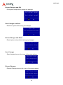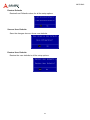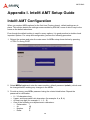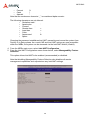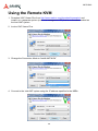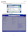
1
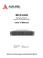
MCS-2040 Media Cloud Server with Four Dual-System Nodes User’s Manual Manual Revision: Revision Date: Part No.: 0.10 February 16, 2014 50-1G041-1010 Advance Technologies; Automate the World. MCS-2040 Revision History Revision 0.10 Release Date 13/02/2015 Description of Change(s) Preliminary release Copyright 2015 ADLINK Technology, Inc. All Rights Reserved. The information in this document is subject to change without prior notice in order to improve reliability, design, and function and does not represent a commitment on the part of the manufacturer. In no event will the manufacturer be liable for direct, indirect, special, incidental, or consequential damages arising out of the use or inability to use the product or documentation, even if advised of the possibility of such damages. This document contains proprietary information protected by copyright. All rights are reserved. No part of this manual may be reproduced by any mechanical, electronic, or other means in any form without prior written permission of the manufacturer. Trademarks Product names mentioned herein are used for identification purposes only and may be trademarks and/or registered trademarks of their respective companies. 2 MCS-2040 Table of Contents Revision History ................................................................................................................... 2 1 Overview .......................................................................................................................... 5 1.1 1.2 1.3 Introduction .............................................................................................................................. 5 Block Diagram.......................................................................................................................... 6 Mechanical Overview ............................................................................................................... 7 1.3.1 1.3.2 1.3.3 1.3.4 1.4 Top View Layout ................................................................................................................................7 Front View Layout..............................................................................................................................8 Rear View Layout ..............................................................................................................................8 Node Layout ......................................................................................................................................9 Package Contents.................................................................................................................. 10 2 Specifications .................................................................................................................11 2.1 2.2 MCS-2040 Specifications........................................................................................................11 Software Support ................................................................................................................... 12 3 Getting Started............................................................................................................... 13 3.1 3.2 3.3 3.4 3.5 3.6 Removing a Node Tray from the Chassis .............................................................................. 13 Installing the CPU .................................................................................................................. 13 Installing the Heatsink ............................................................................................................ 16 Installing the mSATA Drives ................................................................................................... 17 Reinserting a Node Tray into the Chassis.............................................................................. 18 Installing 2.5’’ SATA Drive ...................................................................................................... 19 4 System Interfaces.......................................................................................................... 21 4.1 Node Rear I/O Layout ............................................................................................................ 21 4.1.1 4.1.2 4.1.3 4.1.4 4.2 4.3 LAN Connector (RJ-45) ...................................................................................................................21 LAN Status LEDs .............................................................................................................................21 USB 2.0 Connectors........................................................................................................................22 VGA Connector................................................................................................................................22 Internal Node Layout.............................................................................................................. 23 Connectors and Jumpers ....................................................................................................... 24 4.3.1 mSATA Connectors..........................................................................................................................24 5 BIOS Setup..................................................................................................................... 25 5.1 5.2 5.3 5.4 Entering BIOS Setup.............................................................................................................. 25 Setup Menu............................................................................................................................ 26 Navigation .............................................................................................................................. 27 Main Setup............................................................................................................................. 30 5.4.1 5.4.2 5.5 Advanced BIOS Setup ........................................................................................................... 32 5.5.1 5.5.2 5.5.3 5.5.4 5.6 CPU Configuration...........................................................................................................................33 SATA Configuration..........................................................................................................................36 USB Configuration ...........................................................................................................................37 Super IO Configuration....................................................................................................................38 Chipset Setup ........................................................................................................................ 40 5.6.1 5.7 5.8 5.9 System & Board Info........................................................................................................................31 System Date/System Time ..............................................................................................................31 PCH-IO Configuration......................................................................................................................40 Boot Setup ............................................................................................................................. 42 Security Setup........................................................................................................................ 44 Save & Exit Menu .................................................................................................................. 45 3 MCS-2040 Appendix I. Intel® AMT Setup Guide ................................................................................ 48 Intel® AMT Configuration................................................................................................................ 48 Using the Web UI............................................................................................................................ 56 Using the Web UI............................................................................................................................ 58 Safety Instructions ............................................................................................................. 60 Consignes de Sécurité Importantes ................................................................................. 61 Getting Service ................................................................................................................... 62 4 MCS-2040 1 Overview 1.1 Introduction The ADLINK MCS-2040 is a high density 2U 19” rackmount media cloud server with 4 dualsystem computer nodes. Each node has two 4th Generation Intel® Core™ i7/i5/3 processor or Intel® Xeon® processor E5 Family (formerly “Haswell”) for two independent systems. Detailed features are outlined below. Four hot-pluggable compute nodes • Two independent systems per node communicate via GbE • 2x 4th Gen Core™ i7/i5/3 processor or Intel® Xeon® processor E5 Family per node (one CPU per system) • 4x DIMMs per node support DDR3 up to 32GB (16GB/system) • 4x GbE RJ-45 ports (2 per system) • 4x hot-swappable 2.5” SATA drive bays (2 per system) • 2x mSATA slots for 3Gb/s SSD modules up to 512GB (1 per system) 2x 1600W redundant power supplies ADLINK MediaManager 5 MCS-2040 1.2 Block Diagram DDR3 DDR3 mini PCIEx8 DDR3 Channel A Haswell CPU_0 Page: 11 DDR3 Channel A Haswell CPU_1 PCIEx8 Page: 39 DDR3 DDR3 DDR3 Channel B Page: 52 Page: 33、 34、 35、 36、 37、 38 DMI FDI DMI Page: 12 DDR3 Channel B Page: 40 FDI Page: 5、 6、 7、 8、 9、 10 USB CONN Page: 24 mSATA mSATA SATA2.0 USB2.0 x2 USB2.0 x2 SWITCH SATA2.0 Page: 25 CODEC ALC662 Page: 53 Intel 8 series Chipset VGA CONN Page: 27 Intel 8 series Chipset HD Audio HD Audio RGB SWITCH Q87 Page: 23 PCIE-x1 Page: 13、 14、 15、 16、 17、 18 Intel I211 Page: 22 MDI USB2.0 x2 SPI FLASH Q87 RGB Intel I211 Page: CODEC ALC662 Page: 51 PCIE-x1 Page: 41、 42、 43、 44、 45、 46 USB2.0 x2 PCIE-x8 SPI FLASH SPI SPI Page: 15 SATA3.0 x2 Page: 43 SATA3.0 x2 Intel I217 Intel I211 SPIO NCT6791D Page: 20 Page: 21 Page: 19 PWM OUT PWM OUT PCIE-x1 PCIE-x1 GPIO LPC GPIO SMBUS LPC SMBUS PCIE-x1 PCIE-x1 Page: 63 SPIO NCT6791D Intel I211 Intel I217 Page: 47 Page: 48 Page: 49 MDI RS232 IC Page: 25 RS232 MDI SIX FAN TACH RS232 IC Double-deck RJ45 UART SIX FAN TACH Page: 53 Page: 64 RS232 UART MDI MDI PWM Compare HEADER HEADER Page: 25 Page: 53 6 Double-deck RJ45 MCS-2040 1.3 Mechanical Overview 1.3.1 Top View Layout Power Buttons Power Buttons SATA Drives Fans Fans System0 System0 System1 System1 7 MCS-2040 1.3.2 Front View Layout System1 Power Button System1 Power Button System0 Power Button System1 SATA Drive System0 SATA Drive System0 Power Button System1 SATA Drive System0 SATA Drive System1 Power Button System1 Power Button System1 SATA Drive System0 SATA Drive System0 Power Button System1 SATA Drive System0 SATA Drive System0 Power Button 1.3.3 Rear View Layout 1600W 1+1 redundant Hot-Swappable Power Supply System1 LED System0 USB/VGA LED Switch Button USB USB/VGA Switch Button USB System0 LED System1 LED VGA VGA System0 LAN System0 LAN USB/VGA Switch Button System1 LAN USB/VGA Switch Button System1 LAN System1 LED System0 LED VGA USB VGA System0 LED System1 LED 8 USB System0 LAN System1 LAN System0 LAN System1 LAN MCS-2040 1.3.4 Node Layout System1 PCIe x16 System1 mSATA System0 mSATA System1 DDR3 DIMMs x2 System1 CPU System0 DDR3 DIMMs x2 System0 CPU Fans 9 MCS-2040 1.4 Package Contents Before opening, please check the shipping carton for any damage. If the shipping carton and contents are damaged, notify the dealer for a replacement. Retain the shipping carton and packing material for inspection by the dealer. Obtain authorization before returning any product to ADLINK. Check that the following items are included in the package. If there are any missing items, contact your dealer: TBD 10 MCS-2040 2 Specifications 2.1 MCS-2040 Specifications Main System (per node) CPU 2x 4th Generation Intel® Core™ i7/i5/i3 processor or Intel® Xeon Processor E3 v3 Family in LGA1150 socket (one CPU per system) Chipset 2x Intel® Q87/H81 Chipset (one per system) Memory Four DDR3-1600 240-pin DIMM sockets, up to 32 GB (16GB per system) BIOS AMI UEFI BIOS on SPI flash memory Intel® PXE pre-boot, ACPI 1.0/2.0 support I/O Interfaces (per node) Graphics Intel® HD Graphics, 1x VGA, up to 1920 x 1440 resolution (switchable between systems) Ethernet 4x 10/100/1000BASE-T Base Interface Channels (two per system) Supports Intel® AMT, remote power on/off/reboot USB Two USB 2.0 ports on front panel (switchable between systems) PCIe Expansion 1x PCIe x16 slot Storage (per node) Drive Bays (per node) 4x 2.5” or 3x 3.5” SATA 6Gb/s hot-swap drive trays Other 2x mSATA slots for 3Gb/s SSD modules up to 512GB (1 per system) Chassis Form Factor 2U rackmount Power Supply 2x 1600W hot-swappable redundant power modules Dimensions 438mm x 88mm x 733mm Fans 12x fans with PWM speed control (3 mounted on each node) Environmental Operating Temp. 0 to 55˚C Storage Temp. -40˚C to 70˚C Humidity 5% to 95%, non-condensed Certification FCC, CE, UL, NEBS Level 3 (design), RoHS compliant Application-Ready Intelligent Platform Software Power 1x ATX power button, rocker type (rear) Bypass 1x bypass button (front) LEDs Power, Bypass Status, Drive Activity 11 MCS-2040 2.2 Software Support Intel® Media SDK: GPU based video processing, supports both Linux and Windows operating systems Supported Software OpenCL SDK: provides customers with the ability to offload portions of their own codec/video filter implementations to the GPU ADLINK MediaManager: supports file-to-stream, stream-tostreaming, file-to-file and streaming-to-file media processing 3rd Party Software Flexible Encoder Infrastructure (FEI) for Intel® Media SDK, designed for customers who need to tweak or augment the h264 encode process Open source H.265 encoder from f265.org 12 MCS-2040 3 Getting Started 3.1 Removing a Node Tray from the Chassis 1. Unlock the node tray by pulling the lever to the right as shown 2. Pull the node tray out of the chassis. It may be necessary to pull very firmly to unplug the SATA drive connectors inside the chassis. 3.2 Installing the CPU 1. Locate the CPU sockets on the board. 13 MCS-2040 2. Press the load lever, move it outwards until it is clear of the retention tab, then raise it 3. Open the load plate and remove the protective cover from the socket. Do not touch the socket contacts or the bottom of the processor. 14 MCS-2040 4. Carefully place the CPU into the socket, making sure the socket notches align with the processor notches and the alignment triangle on the CPU lines up with the correct corner on the socket,. Lower the processor straight down, without tilting or sliding the processor in the socket. Gently release the processor, making sure that it is seated correctly in the socket. 5. Close the load plate, push the load lever back down, and engage it with the retention tab. 15 MCS-2040 3.3 Installing the Heatsink 1. Make sure there is sufficient thermal paste on of the heatsink 2. Place the heatsink on the CPU with the cooling fins aligned with the DIMM slots as shown. 3. Tighten the captive screws in an "X" pattern until the heatsink is secured on the CPU. Do NOT over tighten the screws 16 MCS-2040 3.4 Installing the mSATA Drives Each node has 2x mSATA slots for 3Gb/s SSD modules up to 512GB (1 per system). System1 PCIe x16 System1 mSATA System0 mSATA 1. Insert the mSATA module into the socket at an angle as shown, then press it down flat against the standoffs on the PCB. 17 MCS-2040 2. Secure the mSATA modules to the node with 2 screws provided with the module. 3.5 Reinserting a Node Tray into the Chassis 1. Carefully insert the node tray into the chassis, checking that the sides of the tray are aligned with guides in the chassis. 2. Slowly push the tray into the chassis until it is fully inserted. Press firmly until the locking tab makes a clicking sound. 18 MCS-2040 3.6 Installing 2.5’’ SATA Drive 1. Push the green tab to unlock the drive tray. 2. Eject the drive tray by lifting the handle as shown. Pull the tray out of the chassis. 3. Loosen the 4 screws shown below and remove the plastic place holder. Install a 2.5’’ SATA drive with the connectors facing towards the back of the tray. Secure the SATA drive to the bracket with the 4 screws. 19 MCS-2040 4. Insert the drive tray back into the chassis. 5. Push the handle until it clicks into the green tab. 20 MCS-2040 4 System Interfaces 4.1 Node Rear I/O Layout System1 LED USB/VGA Switch Button System0 LED USB VGA System0 LAN System1 LAN 4.1.1 LAN Connector (RJ-45) Left LED 1 Right LED 8 Pin 1 2 3 4 5 6 7 8 Signal MID0+ MID0MID1+ MID2+ MID2MID1MID3+ MID3- 4.1.2 LAN Status LEDs LED Left Right Status 10 Mbps 100 Mbps 1000 Mbps LINK with no activity LINK with activity Link down 21 LED Color Off Amber Green Yellow Yellow Blinking Off MCS-2040 4.1.3 USB 2.0 Connectors Pin 1 2 3 4 Signal Vcc USB_DUSB_D+ GND 4.1.4 VGA Connector Pin Signal Pin Signal 1 Red 2 Green 3 Blue 4 N.C. 5 GND 6 GND 7 GND 8 GND 9 +5V. 10 GND 11 N.C. 12 CRTDATA 13 HSYNC 14 VSYNC 15 CRTCLK 8 22 MCS-2040 4.2 Internal Node Layout A: System 0 DIMM slot B: System 0 MEM power C: PCIe x8 slot – supply +12V power D: System 1 MEM power E: System 1 DIMM slot f: PCIe x8 slot – SATA, USB, FAN ctrl and Power ctrl signal G: System 1 SIO – HW monitor and FAN ctrl H: System 1 audio codec I: System 0/1 battery J: System 0/1 LAN PHY K: 1x 2 RJ-45 connector L: System0 CPU core power M: System 0 CPU N: System1 CPU core power O: System 0 +3.3V power P: System 0 +1.05V power Q: System 0 PCH R: System 0 audio codec S: System 0/1 LAN PHY(w/ MAC) internal connected T: System 0 Mini PCIE slot- used as mSATA interface U: Standard PCIEx16 slot – connect to system 1 V: System 1 +5V power W: System 0 +5V power X: Switch button – switch USB and VGA signal between System 0 and 1 Y: USB connector Z: VGA connector 23 MCS-2040 4.3 Connectors and Jumpers 4.3.1 mSATA Connectors 1 2 Pin 1 1 3 5 7 9 11 13 15 Signal NC NC NC NC GND NC NC GND Pin 2 4 6 8 10 12 14 16 Signal P3V3 GND P1V5 NC NC NC NC NC 17 19 21 23 25 27 29 31 33 35 37 39 41 43 45 47 49 51 NC NC NC RXP0_R RXN0_R GND GND TXN0_R TXP0_R GND GND P3V3 P3V3 NC NC NC NC NC 18 20 22 24 26 28 30 32 34 36 38 40 42 44 46 48 50 52 GND NC NC P3V3 GND P1V5 NC NC GND NC NC GND NC NC NC P1V5 GND P3V3 24 MCS-2040 5 BIOS Setup The following chapter describes basic navigation for the MCS-2040 BIOS setup utility. 5.1 Entering BIOS Setup To enter the setup screen, follow these steps: 1. Power on the motherboard 2. Press the < Delete > key on your keyboard when you see the following text prompt: < Press DEL to enter Setup > 3. After you press the < Delete > key, the main BIOS setup menu displays. You can access the other setup screens from the main BIOS setup menu, such as Chipset and Power menus. In most cases, the < Delete > key is used to invoke the setup screen. However, there are several cases that use other keys, such as < F1 >, < F2 >, and so on. 25 MCS-2040 5.2 Setup Menu The Main BIOS setup menu is the first screen that you can navigate to. The Main BIOS setup menu screen has two main frames. The left frame displays all the options that can be configured. “Grayed” options cannot be configured, and “Blue” options can be. The right frame displays the key legend. Above the key legend is an area reserved for a text message. When an option is selected in the left frame, it is highlighted in white. Often a text message will accompany it. 26 MCS-2040 5.3 Navigation The BIOS setup/utility uses a key-based navigation system called hot keys. Most of the BIOS setup utility hot keys can be used at any time during the setup navigation process. These keys include < F1 >, < F10 >, < Enter >, < ESC >, < Arrow > keys, and so on. There is a hot key legend located in the right frame on most setup screens. →← ↑↓ +- Tab Left/Right. The Left and Right < Arrow > keys allow you to select a setup screen. For example: Main screen, Advanced screen, Chipset screen, and so on. Up/Down The Up and Down < Arrow > keys allow you to select a setup item or sub-screen. Plus/Minus The Plus and Minus < Arrow > keys allow you to change the field value of a particular setup item. For example: Date and Time. The < Tab > key allows you to select setup fields. Hot Key Description Enter The < Enter > key allows you to display or change the setup option listed for a particular setup item. The < Enter > key can also allow you to display the setup sub-screens. 27 MCS-2040 F1 F2 F3 The < F1 > key allows you to display the General Help screen. Press the < F1 > key to open the General Help screen. The < F2 > key on your keyboard is the previous values key. It is not displayed on the key legend by default. To set the previous values settings of the BIOS, press the < F2 > key on your keyboard. It is located on the upper row of a standard 101 keyboard. The previous value settings allow the motherboard to boot up with the least amount of options set. This can lessen the probability of conflicting settings. Press the < Enter > key to load previous values. You can also use the < Arrow > key to select Cancel and then press the < Enter > key to abort this function and return to the previous screen. The < F3 > key on your keyboard is the optimized defaults key. To set the optimized defaults settings of the BIOS, press the < F3 > key on your keyboard. It is located on the upper row of a standard 101 keyboard. The optimized defaults settings allow the motherboard to boot up with the optimized defaults of options set. This can lessen the probability of conflicting settings. Press the < Enter > key to load optimized defaults. You can also use the < Arrow > key to select Cancel and then press the < Enter > key to abort this function and return to the previous screen. 28 MCS-2040 F4 ESC The < F4 > key allows you to save any changes you have made and exit Setup. Press the < F4 > key to save your changes. The following screen will appear: Press the < Enter > key to save the configuration and exit. You can also use the < Arrow > key to select Cancel and then press the < Enter > key to abort this function and return to the previous screen. The < Esc > key allows you to discard any changes you have made and exit the Setup. Press the < Esc > key to exit the setup without saving your changes. The following screen will appear: Press the < Enter > key to discard changes and exit. You can also use the < Arrow > key to select Cancel and then press the < Enter > key to abort this function and return to the previous screen. 29 MCS-2040 5.4 Main Setup When you first enter the Setup Utility, you will find the Main setup screen. You can always return to the Main setup screen by selecting the Main tab. There are two Main Setup options. They are described in this section. The Main BIOS Setup screen is shown below. 30 MCS-2040 5.4.1 System & Board Info The Main BIOS setup screen reports processor, memory and board information. BIOS Vendor Displays the BIOS vendor. Core Version Displays the BIOS core version. Compliancy Version Displays the current UEFI Specification version. BIOS Version Displays the current BIOS version. Build Data and Time Displays the BIOS build data and time. System Language Displays default system language. Board ID Displays the system in use (System 0 or System 1). 5.4.2 System Date/System Time Use this option to change the system time and date. Highlight System Time or System Date using the < Arrow > keys. Enter new values using the keyboard. Press the < Tab > key or the < Arrow > keys to move between fields. The date must be entered in MM/DD/YY format. The time is entered in HH:MM:SS format. The time is in 24-hour format. For example, 5:30 A.M. appears as 05:30:00, and 5:30 P.M. as 17:30:00. 31 MCS-2040 5.5 Advanced BIOS Setup Select the Advanced tab from the setup screen to enter the Advanced BIOS Setup screen. You can select any of the items in the left frame of the screen, (ex: Super IO Configuration), to go to the sub menu for that item. You can display an Advanced BIOS Setup option by highlighting it using the < Arrow > keys. The Advanced BIOS Setup screen is shown below. The sub menus are described on the following pages. 32 MCS-2040 5.5.1 CPU Configuration You can use this screen to select options for the CPU Configuration Settings. Use the up and down < Arrow > keys to select an item. Use the < + > and < - > keys to change the value of the selected option. A description of the selected item appears on the right side of the screen. The settings are described on the following pages. An example of the CPU Configuration screen is shown below. 33 MCS-2040 Hyper-threading Enabled for Windows XP and Linux (OS optimized for Hyper-Threading Technology) and Disabled for other OS (OS not optimized for Hyper-Threading Technology). Options Enabled Disabled For Windows XP and Linux (OS optimized for Hyper-Threading Technology). For other OS (OS not optimized for Hyper-Threading Technology). Active Processor Core Number of cores to enable in each processor package. Set this value to All, 1, 2, 3. Limit CPUID Maximum The Limit CPUID Maximum allows you to circumvent problems with older operating systems that do not support Hyper-Threading Technology. When enabled, the processor will limit the maximum CPUID input value to 03h when queried, even if the processor supports a higher CPUID input value. When disabled, the processor will return the actual maximum CPUID input value of the processor when queried. Execute Disable Bit Execute Disable Bit (EDB) is an Intel hardware-based security feature that can help reduce system exposure to viruses and malicious code. EDB allows the processor to classify areas in memory where application code can or cannot execute. Set this value to Enabled/Disabled. Intel Virtualization Technology When enabled, a VMM can utilize the additional hardware capability provided by Vanderpool Technology. Set this value to Enabled/Disabled. Hardware Prefetcher When Enabled, the processor's hardware prefetcher will be enabled and allowed to automatically prefetch data and code for the processor. When Disabled, the processor's hardware prefetcher will be disabled. Adjacent Cache Line Prefetch The processor has a hardware adjacent cache line prefetch mechanism that automatically fetches an extra 64-byte cache line whenever the processor requests for a 64-byte cache line. This reduces cache latency by making the next cache line immediately available if the processor requires it as well. When enabled, the processor will retrieve the currently requested cache line, as well as the subsequent cache line. When disabled, the processor will only retrieve the currently requested cache line. 34 MCS-2040 CPU AES Select Enable for Intel CPU Advanced Encryption Standard (AES) Instructions support to enhance data integrity. The options are Enabled and Disabled. Boot Performance Mode This feature selects the performance state the BIOS will set before the OS hand-off. The options are Max Non-Turbo Performance and Turbo Performance. EIST Enable Intel SpeedStep Technology support. Set this value to Enabled/Disabled. Turbo Mode Enable Intel Turbo Boost support. Set this value to Enabled/Disabled. Energy Performance Use this feature to select an appropriate fan setting to achieve the maximum system performance (with maximum cooling) or maximum energy efficiency (with maximum power saving). The fan speeds are controlled by the firmware management. The options are Performance, Balanced Performance, Balanced Energy, and Energy Efficient. 35 MCS-2040 5.5.2 SATA Configuration You can use this screen to select options for the SATA Configuration Settings. An example of the SATA Configuration screen is shown below. SATA Controller(s) Enables or disables SATA device. SATA Mode Selection The SATA can be configured as a legacy IDE, AHCI and RAID mode. SATA Port 0-4 Displays SATA device name string. Port 0-4 Enable or disable the SATA Port. Hot Plug Appears when SATA mode is set to AHCI. SATA Ports Hot Plug support. Set this value to Enabled/Disabled. 36 MCS-2040 5.5.3 USB Configuration You can use this screen to select options for the USB Configuration Settings. Use the up and down < Arrow > keys to select an item. Use the < + > and < - > keys to change the value of the selected option. A description of the selected item appears on the right side of the screen. The settings are described on the following pages. An example of the USB Configuration screen is shown below. Legacy USB Support Enables legacy USB support. Auto option disables legacy support if no USB devices are connected. The disable option will keep USB devices available only for EFI applications. Set this value to Enabled/Disabled/Auto. EHCI Hand-off This item is for Operating Systems that do not support Enhanced Host Controller Interface (EHCI) hand-off. When this item is enabled, EHCI ownership change will be claimed by the EHCI driver. The settings are Enabled and Disabled. 37 MCS-2040 5.5.4 Super IO Configuration NCT6791D HW Monitor CPU Temperature Displays current CPU temperature. SYSFan1 - SYSFan5 speed Displays current system Fan RPM. 38 MCS-2040 3.3V Displays current system 3.3V voltage. 12V Displays current system 12V voltage. 1.05V Displays current system 1.05V voltage. VDDQ Displays current system VDDQ voltage. CPUVcore Displays current system Vcore voltage. 39 MCS-2040 5.6 Chipset Setup Select the Chipset tab from the setup screen to enter the Chipset BIOS Setup screen. You can select any of Chipset BIOS Setup options by highlighting an option using the < Arrow > keys. The Chipset BIOS Setup screen is shown below. 5.6.1 PCH-IO Configuration PCH LAN Controller Enable or Disable the Intel Platform Controller Hub LAN controller. 40 MCS-2040 5.6.1.1 PCH Azalia Configuration Azalia When set to Disabled, Azalia will be unconditionally disabled. When set to Enabled, Azalia will be unconditionally Enabled. When set to Auto, Azalia will be enabled if present, disabled otherwise. 41 MCS-2040 5.7 Boot Setup Select the Boot tab from the setup screen to enter the Boot BIOS Setup screen. You can select any of the items in the left frame of the screen, such as Boot Device Priority, to go to the sub menu for that item. You can display a Boot BIOS Setup option by highlighting it using the < Arrow > keys. The Boot Settings screen is shown below: Setup Prompt Timeout Set the number of seconds that the system will wait for the setup activation key. The number of 65535(0xFFFF) means indefinite waiting. Bootup NumLock State Select the keyboard NumLock state. Set this value to On, Off. Quiet Boot Disabled - Set this value to allow the computer system to display the POST messages. Enabled - Set this value to allow the computer system to display the OEM logo. 42 MCS-2040 Fixed Boot Option Priorities Set Boot Option #1 to #7 boot priority. Hard Drive BBS Priorities Specifies the boot device priority sequence from available hard drives. 43 MCS-2040 5.8 Security Setup Administrator / User Password If only the administrator’s password is set, then this limits access to setup and is only asked for when entering setup. If only the user’s password is set, then this is a power on password and must be entered to boot or enter setup. In setup the user will have administrator rights. 44 MCS-2040 5.9 Save & Exit Menu Select the Exit tab from the setup screen to enter the Exit BIOS Setup screen. You can display an Exit BIOS Setup option by highlighting it using the < Arrow > keys. The Exit BIOS Setup screen is shown below. Save Changes and Exit Exit system setup after saving the changes. 45 MCS-2040 Discard Changes and Exit Exit system setup without saving any changes. Save Changes and Reset Reset the system after saving the changes. Discard Changes and Reset Reset system setup without saving any changes. Save Changes Save changes done so far to any of the setup options. Discard Changes Discard Changes done so far to any of the setup options. 46 MCS-2040 Restore Defaults Restore/Load Defaults values for all the setup options. Save as User Defaults Save the changes done so far as user defaults. Restore User Defaults Restore the user defaults to all the setup options. 47 MCS-2040 Appendix I. Intel® AMT Setup Guide Intel® AMT Configuration When you explore MEBx options for the first time (Factory phase), default settings are in place. This section details the settings recommended by ADLINK, some of which may be the same as the default selections. Even though the default setting is used for many options, it is good practice to double-check important options. For setup and configuration, perform the following procedure: 1. Reboot the system and enter the main menu for MEBx setup shown below by pressing <CTRL-P> during POST. 2. Select MEBx Login and enter the case-sensitive, default password (admin), which must be changed before making any changes in the MEBx. 3. Provide a strong, new MEBx password using the criteria listed below. Repeat the password for verification. • • • • 8 – 32 characters long Upper- and lower-case Latin characters (for example: A, a, B, b) At least one digit (for example: 0, 1, 2… 9). One of the following non-alphanumeric characters: à Exclamation ! à At @ à Number # à Dollar $ 48 MCS-2040 à Percent % à Caret ^ à Asterisk * Note that the underscore character “_” is considered alpha-numeric. The following characters are not allowed: à Quotation mark “ à Apostrophe ‘ à Comma , à Greater than > à Less than < à Colon : à Ampersand & à Space Changing the password establishes Intel AMT ownership and moves the system from Factory to In-Setup phase. As a result, ME and Intel AMT options are now accessible within the MEBx; the system can be accessed via the Intel AMT WebUI (WebUI). 4. From the MEBx main menu, select Intel AMT Configuration. 5. From the Intel AMT Configuration menu shown below, select Manageability Feature Selection. This option allows Intel AMT to be enabled (recommended) or disabled. Note that disabling Manageability Feature Selection also disables all remote management capabilities and unprovisions any Intel AMT settings. 49 MCS-2040 6. From the Intel AMT Configuration menu, select SOL/IDER/KVM. The SOL/IDER/KVM screen appears, as shown below. Review the following settings: Username and password: Enabled (Recommended setting; default) When enabled, this setting allows users and passwords to be added via the WebUI; if it is disabled, only the administrator has MEBx remote access. SOL: Enabled (Recommended setting; default) This setting enables or disables Serial-over-LAN (SOL) functionality. IDER: Enabled (Recommended setting; default) This setting enables or disables IDE Redirection (IDE-R) functionality. KVM Feature Selection: Enabled (Recommended setting; default) This setting enables or disables the keyboard/video/mouse feature. Legacy Redirection Mode: Enabled (Recommended setting; Enabled) This setting allows the redirection feature to work with a pre-Intel AMT 6.0 SCS. 7. From the Intel AMT Configuration menu, select User Consent. The User Consent screen appears, as shown below. Review the following settings: User Opt-in: NONE (Setting is user-dependent; recommended setting; NONE) This setting is used to control remote KVM operating, the server must provide one-time password for remote KVM. Opt-in Configurable from Remote IT: Enabled (Setting is user-dependent; Enabled by default). This setting enables or disables a remote user’s ability to select user opt-in policy. If set to disabled, only the local user can control the opt-in policy. 50 MCS-2040 8. Review the Password Policy setting shown in the Intel AMT Configuration screen. This setting specifies when it is possible to change the MEBx password over the network. As shown below, options are: Default Password Only You can change the MEBx password via the network interface if the default password has not yet been changed. During Setup and Configuration You can change the MEBx password via the network interface during the setup and configuration process but at no other time. Once setup and configuration is complete, the password cannot be changed via the network interface. Anytime (recommended; default setting) You can change the MEBx password via the network interface at any time. 51 MCS-2040 9. Select Network Setup from the Intel AMT Configuration menu. The Intel ME Network Setup screen appears, as shown below, allowing you to configure Intel AMT so that it can be accessed by a remote system. 10. Select Intel ME Network Name Settings from the Intel ME Network Setup menu. The Intel ME Network Name Settings screen appears, as shown below. 52 MCS-2040 Review the following settings: Host Name: (Setting is user-dependent; there is no default) Host names can be used in place of the system’s IP address for any application that requires this address. Domain Name: (Setting is network-dependent; there is no default) If a domain name is not specified, then the default domain name of Provisionserver will be used when connecting to the SCS. If a domain name is not specified and the domain name for the SCS is not Provisionserver, you must set up an alias in the DHCP server to redirect the connection for Provisionserver to the appropriate domain. If a domain name is specified, then that domain will be used. However, if there is no response after four DNS queries to the specified domain, Provisionserver will be used instead. Shared/Dedicated FDQN: Shared (Recommended setting; default) This setting determines whether the Intel ME Fully Qualified Domain Name (FQDN) – that is, the HostName. DomainName – is shared with the operating system or is in a separate domain. Dynamic DNS Update: Disabled (Recommended setting; default) If Dynamic DNS (DDNS) update is enabled, the firmware will actively try to register its IP addresses and FQDN in DNS using DDNS update protocol. You must set the appropriate host and domain names; in addition, the MEBx menu displays the following options: • Periodic Update Interval: Specify a time from 20 to 1,440 minutes • TTL (time-to-live): Specify a time in seconds If DDNS update is disabled, the firmware will make no attempt to update DNS using DHCP option 81 or DDNS update protocol. If DDNS update has not been set (that is, it is neither enabled nor disabled), the firmware will use DHCP option 81 for DNS registration; it will not directly update DNS using DDNS update protocol. 53 MCS-2040 11. At the Intel ME Network Setup menu (Step 9 above), select TCP/IP Settings. The TCP/IP Settings screen appears, as shown below. 12. Select Wired LAN IPV4 Configuration and then configure the parameters shown below. DHCP Mode: Enabled (Recommended setting; default) If DHCP is enabled (recommended), skip to Step 16. If DHCP is disabled, configure an IPv4 static IP address for Intel AMT. 54 MCS-2040 IPV4 Address: (Network-dependent; default is 0.0.0.0 Specify the desired static IP address (such as 192.168.0.1). Ensure that each Intel AMT system has a unique IP address. Multiple systems sharing the same IP address may result in network collisions that would cause the systems to respond incorrectly. Subnet Mask Address: (Network-dependent; default is 255.255.255.0) Default Gateway Address: (Network-dependent; default is 0.0.0.0) Preferred DNS Address: (Network-dependent; default is 0.0.0.0) Alternate DNS Address: (Network-dependent; default is 0.0.0.0) 13. Having completed the network setup, select Activate Network Access from the Intel AMT Configuration menu, as shown below. This setting causes the ME to transition to the newly-provisioned state if all required settings have been configured. The Unconfigure Network Access option causes the ME to transition to the preprovisioned state. 14. When MEBx displays Update Network Settings in the General Settings menu, press Enter. 15. At the MEBx CAUTION prompt, press Y. 16. Press the ESC key to return to the MEBx Main Menu and select MEBx Exit to exit the MEBx setup and save settings. The system will reboot. Once the system reboots, it changes from Intel AMT In-Setup phase to Operational phase. Now, the system can be remotely managed through the WebUI or a remote console and can be provided to the end-user for regular use. 55 MCS-2040 Using the Web UI The WebUI is a browser-based interface that provides limited support for remote system management. It is often used to verify that Intel AMT setup and configuration has been performed properly on a system. Obtaining a successful connection between a remote system and the system running the WebUI indicates proper Intel AMT setup and configuration on the remote system. The WebUI is accessible from the following web browsers: • Microsoft Internet Explorer 6 SP1 or newer • Mozilla Firefox Remote system management capabilities include: • Hardware inventory • Event logging • Remote system reset • Updating network settings • Adding new users and passwords • Updating ME firmware WebUI support is enabled by default for Manual mode setup and configuration. Connecting with the WebUI in Manual mode 1 2 3 Power on an Intel AMT system that is in its operational phase. Invoke a web browser on a separate system (such as a management PC) that is on the same subnet as the Intel AMT system. Connect to the Intel AMT system using the IP address and port specified in the MEBx. • • By default, the port is 16992 If DHCP has been specified, then use the Fully Qualified Domain Name (FQDN) for the ME, which is a combination of the hostname and domain as in the following examples: à IPv4 address: http://172.20.5.218:16992 à Host names (see Host Name in Step 10 of AMT Configuration above) http://MCS-2040-AMT:16992 The remote system makes a TCP connection to the Intel AMT system and accesses the toplevel web page embedded within the ME. 56 MCS-2040 4. Enter your username and password. The default username is admin, while the password is the one specified during ME setup. After login, the System Status screen appears, as shown below. 5. Review the system information and make any necessary changes. 6. Exit. 57 MCS-2040 Using the Remote KVM 1. Download VNC Viewer Plus from http://www.realvnc.com/download/viewerplus/ and install it on a separate system (such as a management PC) that is on the same subnet as the Intel AMT system. 2. Invoke VNC Viewer Plus 3. Change the Connection Mode to “Intel® AMT KVM” 4. Connect to the Intel AMT system using the IP address specified in the MEBx. 58 MCS-2040 5. Enter your username and password. The default username is admin, while the password is the one specified during ME setup. 6. After login, the system screen appears. 59 MCS-2040 Safety Instructions For user safety, please read and follow all instructions, WARNINGS, CAUTIONS, and NOTES marked in this manual and on the associated equipment before handling/operating the equipment. 1. Read these safety instructions carefully. 2. Keep this user’s manual for future reference. 3. Read the specifications section of this manual for detailed information on the operating environment of this equipment. 4. The equipment can be operated at an ambient temperature of 55°C. 5. When installing/mounting or uninstalling/removing equipment; or when removal of the chassis lid required for user servicing: • Turn off power and unplug any power cords/cables, and • Reinstall the chassis lid before restoring power. 6. To avoid electrical shock and/or damage to equipment: • Keep equipment away from water or liquid sources; • Keep equipment away from high heat or high humidity; • Keep equipment properly ventilated (do not block or cover ventilation openings); • Make sure to use recommended voltage and power source settings; • Always install and operate equipment near an easily accessible electrical socketoutlet; • Secure the power cord (do not place any object on/over the power cord); • Only install/attach and operate equipment on stable surfaces and/or recommended mountings; • If the equipment will not be used for long periods of time, turn off and unplug the equipment from its power source. 7. Never attempt to fix the equipment. Equipment should only be serviced by qualified personnel. 8. A Lithium-type battery may be provided for uninterrupted, backup or emergency power. CAUTION! Risk of explosion if battery is replaced with one of an incorrect type. Please dispose of used batteries appropriately. 9. Equipment must be serviced by authorized technicians when: • The power cord or plug is damaged; • Liquid has penetrated the equipment; • It has been exposed to high humidity/moisture; • It is not functioning or does not function according to the user’s manual; • It has been dropped and/or damaged; and/or, • It has an obvious sign of breakage. 10. Please pay strict attention to all warnings and advisories appearing on the device, to avoid injury or damage. 11. The equipment may have more than one power supply input. To reduce the risk of electrical shock, trained personnel should disconnect all power supply inputs before servicing. CAUTION! Disconnect all power supply inputs before servicing. 60 MCS-2040 Consignes de Sécurité Importantes Pour assurer la sécurité de l’utilisateur, veuillez lire et suivre toutes les directives, ainsi que les AVERTISSEMENTS, MISES EN GARDE et REMARQUES de ce manuel et indiqués sur l’équipement associé avant de manipuler ou utiliser l’équipement. 1. Veuillez lire attentivement ces instructions de sécurité avec soin. 2. Veuillez conserver ce manuel pour référence future. 3. Veuillez lire la section des spécifications de ce manuel pour avoir des informations détaillées sur l’environnement d’exploitation de cet équipement. 4. L’équipement peut être utilisé à une température ambiante de 55 °C. 5. Lors de l’installation ou du montage et de la désinstallation ou de la dépose de l’équipement; ou lors de la dépose du couvercle du châssis pour procéder à l’entretien par l’utilisateur: • Coupez l’alimentation et débranchez les cordons et les câbles d’alimentation, et • Reposez le couvercle du châssis avant de remettre l’alimentation. 6. Pour éviter un risque d’électrocution et pour éviter d’endommager l’équipement : • Éloignez l’équipement de l’eau et de toute source liquide; • Éloignez l’équipement de toute source de chaleur ou d’humidité élevée; • Gardez l’équipement correctement ventilé (ne pas bloquer ou couvrir les ouvertures de ventilation); • Veillez à utiliser la tension recommandée et les réglages adéquats pour la source d’alimentation; • Veuillez toujours installer et exploiter l’équipement à proximité d’une prise de courant facilement accessible; • Assurez-vous que le cordon d’alimentation est acheminé de manière sécuritaire (ne déposez aucun objet dessus); • Installez, fixez et utilisez l’équipement sur des surfaces stables ou sur les fixations recommandées uniquement; • Si l’équipement n’est pas utilisé pendant une longue période, éteignez-le et débranchez-le de sa source d’alimentation. 7. N’essayez jamais de réparer l’équipement. L’équipement ne doit être réparé que par du personnel qualifié. 8. Une pile au lithium peut être installée pour assurer l’alimentation de secours ou d’urgence en continu. ATTENTION! Risque d’explosion si la pile est remplacée par une autre de type incorrect. Veuillez jeter les piles usagées de façon appropriée. 9. L’équipement doit être entretenu par des techniciens agréés lorsque : • le cordon d’alimentation est endommagé ou lorsque la fiche électrique est endommagée; • du liquide a pénétré à l’intérieur de l’équipement; • l’équipement a été exposé à un taux d’humidité élevé; • l’équipement ne fonctionne pas ou ne fonctionne pas conformément au manuel de l’utilisateur; • l’équipement est tombé ou lorsqu’il a été endommagé; • l’équipement présente un signe évident de défaillance. 10. Veuillez porter une attention rigoureuse à tous les avertissements et à tous les avis figurant sur l’appareil, pour éviter des blessures ou des dommages. 11. ATTENTION! L’équipement peut avoir plus d’une entrée d’alimentation. Pour réduire le risque d’électrocution, le personnel qualifié devrait déconnecter toutes les entrées d’alimentation avant de procéder à l’entretien. 61 MCS-2040 Getting Service Contact us should you require any service or assistance. ADLINK Technology, Inc. Address: 9F, No.166 Jian Yi Road, Zhonghe District New Taipei City 235, Taiwan 新北市中和區建一路 166 號 9 樓 Tel: +886-2-8226-5877 Fax: +886-2-8226-5717 Email: [email protected] Ampro ADLINK Technology, Inc. Address: 5215 Hellyer Avenue, #110, San Jose, CA 95138, USA Tel: +1-408-360-0200 Toll Free: +1-800-966-5200 (USA only) Fax: +1-408-360-0222 Email: [email protected] ADLINK Technology (China) Co., Ltd. Address: 上海市浦东新区张江高科技园区芳春路 300 号 (201203) 300 Fang Chun Rd., Zhangjiang Hi-Tech Park, Pudong New Area Shanghai, 201203 China Tel: +86-21-5132-8988 Fax: +86-21-5132-3588 Email: [email protected] ADLINK Technology Beijing Address: 北京市海淀区上地东路 1 号盈创动力大厦 E 座 801 室(100085) Rm. 801, Power Creative E, No. 1, B/D, Shang Di East Rd. Beijing, 100085 China Tel: +86-10-5885-8666 Fax: +86-10-5885-8625 Email: [email protected] ADLINK Technology Shenzhen Address: 深圳市南山区科技园南区高新南七道 数字技术园 A1 栋 2 楼 C 区 (518057) 2F, C Block, Bldg. A1, Cyber-Tech Zone, Gao Xin Ave. Sec. 7 High-Tech Industrial Park S., Shenzhen, 518054 China Tel: +86-755-2643-4858 Fax: +86-755-2664-6353 Email: [email protected] LiPPERT ADLINK Technology GmbH Address: Hans-Thoma-Strasse 11, D-68163, Mannheim, Germany Tel: +49-621-43214-0 Fax: +49-621 43214-30 Email: [email protected] 62 MCS-2040 ADLINK Technology, Inc. (French Liaison Office) Address: 6 allée de Londres, Immeuble Ceylan 91940 Les Ulis, France Tel: +33 (0) 1 60 12 35 66 Fax: +33 (0) 1 60 12 35 66 Email: [email protected] ADLINK Technology Japan Corporation Address: 〒101-0045 東京都千代田区神田鍛冶町 3-7-4 神田 374 ビル 4F KANDA374 Bldg. 4F, 3-7-4 Kanda Kajicho, Chiyoda-ku, Tokyo 101-0045, Japan Tel: +81-3-4455-3722 Fax: +81-3-5209-6013 Email: [email protected] ADLINK Technology, Inc. (Korean Liaison Office) Address: 137-881 서울시 서초구 서초대로 326, 802 (서초동, 모인터빌딩) 802, Mointer B/D, 326 Seocho-daero, Seocho-Gu, Seoul 137-881, Korea Tel: +82-2-2057-0565 Fax: +82-2-2057-0563 Email: [email protected] ADLINK Technology Singapore Pte. Ltd. Address: 84 Genting Lane #07-02A, Cityneon Design Centre, Singapore 349584 Tel: +65-6844-2261 Fax: +65-6844-2263 Email: [email protected] ADLINK Technology Singapore Pte. Ltd. (Indian Liaison Office) Address: #50-56, First Floor, Spearhead Towers Margosa Main Road (between 16th/17th Cross) Malleswaram, Bangalore - 560 055, India Tel: +91-80-65605817, +91-80-42246107 Fax: +91-80-23464606 Email: [email protected] ADLINK Technology, Inc. (Israeli Liaison Office) Address: 27 Maskit St., Corex Building PO Box 12777 Herzliya 4673300, Israel Tel: +972-54-632-5251 Fax: +972-77-208-0230 Email: [email protected] ADLINK Technology, Inc. (UK Liaison Office) Tel: +44 774 010 59 65 Email: [email protected] 63