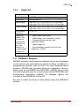
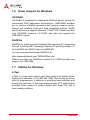
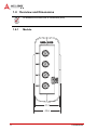
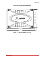
1
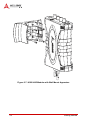
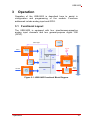
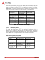
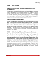
USB-2405 USB 2.0-based Dynamic Signal Acquisition Module User’s Manual Manual Rev.: 2.00 Revision Date: July 5, 2013 Part No: 50-1Z148-1000 Advance Technologies; Automate the World. Revision History ii Revision Release Date Description of Change(s) 2.00 July 5, 2013 Initial release USB-2405 Preface Copyright 2013 ADLINK Technology, Inc. This document contains proprietary information protected by copyright. All rights are reserved. No part of this manual may be reproduced by any mechanical, electronic, or other means in any form without prior written permission of the manufacturer. Disclaimer The information in this document is subject to change without prior notice in order to improve reliability, design, and function and does not represent a commitment on the part of the manufacturer. In no event will the manufacturer be liable for direct, indirect, special, incidental, or consequential damages arising out of the use or inability to use the product or documentation, even if advised of the possibility of such damages. Environmental Responsibility ADLINK is committed to fulfill its social responsibility to global environmental preservation through compliance with the European Union's Restriction of Hazardous Substances (RoHS) directive and Waste Electrical and Electronic Equipment (WEEE) directive. Environmental protection is a top priority for ADLINK. We have enforced measures to ensure that our products, manufacturing processes, components, and raw materials have as little impact on the environment as possible. When products are at their end of life, our customers are encouraged to dispose of them in accordance with the product disposal and/or recovery programs prescribed by their nation or company. Trademarks Product names mentioned herein are used for identification purposes only and may be trademarks and/or registered trademarks of their respective companies. Preface iii Conventions Take note of the following conventions used throughout this manual to make sure that users perform certain tasks and instructions properly. Additional information, aids, and tips that help users perform tasks. NOTE: CAUTION: WARNING: iv Information to prevent minor physical injury, component damage, data loss, and/or program corruption when trying to complete a task. Information to prevent serious physical injury, component damage, data loss, and/or program corruption when trying to complete a specific task. Preface USB-2405 Table of Contents Revision History...................................................................... ii Preface .................................................................................... iii List of Figures ....................................................................... vii List of Tables.......................................................................... ix 1 Introduction ........................................................................ 1 1.1 Overview.............................................................................. 1 1.2 Features............................................................................... 1 1.3 Applications ......................................................................... 2 1.4 Specifications....................................................................... 2 1.4.1 General Specifications................................................ 2 1.4.2 Analog Input (AI)......................................................... 2 1.4.3 DC accuracy @25°C .................................................. 3 1.4.4 AC Dynamic Performance (typical, 25°C) .................. 3 1.4.5 Digital I/O.................................................................... 5 1.5 Software Support ................................................................. 5 1.6 Driver Support for Windows................................................. 6 1.7 Utilities for Windows ............................................................ 6 1.8 Overview and Dimensions ................................................... 8 1.9 1.8.1 Module........................................................................ 8 1.8.2 Module Stand ........................................................... 10 Connections....................................................................... 16 2 Getting Started ................................................................. 17 2.1 Unpacking the USB-2405 .................................................. 17 2.2 Connecting the USB-2405 Module .................................... 17 2.3 Device ID ........................................................................... 19 2.4 Device Mounting ................................................................ 20 Table of Contents v 2.5 2.4.1 Rail Mounting............................................................ 20 2.4.2 Wall Mounting ........................................................... 23 Hardware Configuration ..................................................... 25 3 Operation ........................................................................... 27 3.1 Functional Layout............................................................... 27 3.2 Analog Input....................................................................... 28 3.3 3.2.1 Analog Input Front End Configuration ...................... 28 3.2.2 AI Data Format ......................................................... 29 3.2.3 Sampling Rate .......................................................... 30 3.2.4 Data Transfer............................................................ 31 3.2.5 Anti-Aliasing Filter and Frequency Response........... 31 Triggering........................................................................... 33 3.3.1 3.4 Analog Input Trigger Source..................................... 33 Programmable Function I/O............................................... 39 3.4.1 Static Digital Input/Output ......................................... 39 3.4.2 Frequency Counter ................................................... 39 3.4.3 Pulse Output ............................................................. 39 3.4.4 Digital Trigger IN for Continuous Analog Input ......... 40 3.4.5 Synchronization Sample Clock IN ............................ 40 4 Calibration ......................................................................... 41 4.1 Loading Calibration Constants........................................... 41 4.2 Auto-Calibration ................................................................. 41 4.3 Saving Calibration Constants............................................. 42 Important Safety Instructions............................................... 43 Getting Service ...................................................................... 45 vi Table of Contents USB-2405 List of Figures Figure 1-1: Figure 1-2: Figure 1-3: Figure 1-4: Figure 1-5: Figure 1-6: Figure 1-7: Figure 1-8: Figure 1-9: Figure 1-10: Figure 1-11: Figure 2-1: Figure 2-2: Figure 2-3: Figure 2-4: Figure 2-5: Figure 2-6: Figure 2-7: Figure 3-1: Figure 3-2: Figure 3-3: Figure 3-4: Figure 3-5: Figure 3-6: Figure 3-7: Figure 3-8: Figure 3-9: Figure 3-10: Figure 3-11: Figure 3-12: Figure 3-13: Figure 3-14: List of Figures U-Test Interface.......................................................... 7 USB-2405 Module Front View .................................... 9 USB-2405 Module Side View ..................................... 9 USB-2405 Module Rear View................................... 10 Module, Stand, and USB Cable................................ 11 Module, Stand, & Wall Mount Kit Side View (w/ Connections)......................................................................... 12 Module In Stand Front View ..................................... 13 Module Stand Top View ........................................... 14 Module Stand Side Cutaway View ........................... 15 Module Stand Front View ......................................... 15 BNC Connector Polarity ........................................... 16 USB-2405 Module in Windows Device Manager...... 18 Device ID Selection Control...................................... 19 Rail Mount Kit ........................................................... 20 Module Pre-Rail Mounting ........................................ 21 Module Rail-Mounted ............................................... 22 Wall Mount Holes ..................................................... 23 USB-2405 Module with Wall Mount Apparatus ........ 24 USB-2405 Functional Block Diagram ....................... 27 USB-2405 Analog Front End .................................... 28 Excitation Current for IEPE Sensor Measurement ... 29 Input Frequency Response for High Resolution Mode (Fs=51.2kS/s) ........................................................... 32 Input Frequency Response for High Speed Mode (Fs=102.4kS/s) ......................................................... 33 Below-Low Analog Triggering................................... 34 Above-High Analog Triggering ................................. 35 Digital Triggering ...................................................... 35 Post Trigger without Retrigger.................................. 36 Pre-trigger Mode Operation (valid trigger only) ........ 36 Pre-trigger Mode Operation (w/ invalid trigger) ........ 37 Delay-Trigger Mode Operation ................................. 37 Middle-Trigger Acquisition ........................................ 38 Gated Trigger ........................................................... 38 vii This page intentionally left blank. viii List of Figures USB-2405 List of Tables Table 1-1: U-Test Interface Legend .................................................. 7 Table 3-1: Signal Source-Card Configuration ................................. 28 Table 3-2: USB-2405 Input Ranges................................................ 30 List of Tables ix This page intentionally left blank. x List of Tables USB-2405 1 Introduction 1.1 Overview The USB-2405 is a 24-bit high-performance dynamic signal acquisition USB module, equipped with 4 simultaneous-sampling analog input channels sampling up to 128 kS/s per channel. The USB-2405 also features software selectable AC or DC coupling input configuration, and built-in high precision 2 mA excitation current to measure integrated electronic piezoelectric (IEPE) sensors such as accelerometers and microphones. The USB-2405 delivers high precision DC and dynamic measurement performance with very low temperature drift. The onboard 24-bit Sigma-Delta ADC supports anti-aliasing, which suppresses modulator and signal out-of-band noise and provides usable signal bandwidth of the Nyquist rate, making it ideal for high dynamic range signal measurement in vibration and acoustic applications. The USB-2405 supports digital and analog trigger sources and flexible trigger modes, including post, delay, middle, gated, and pre-triggering, which acquires data efficiently without post processing. The USB-2405 is USB bus powered and equipped with BNC connectors and removable spring terminals for easy device connectivity. 1.2 Features X Hi-Speed USB 2.0 X USB bus powered X 24-bit Sigma-Delta ADC with built-in anti-aliasing filter X 4-CH simultaneous sampling analog input, up to 128kS/s X AC or DC input coupling, software selectable X Analog or digital triggering X Supports 2mA excitation output on each analog input channel for IEPE sensor measurement X Full auto-calibration X Ready-to-use testing application (U-Test) provided Introduction 1 1.3 Applications X Vibration testing X Machine condition monitoring X Acoustic measurement X Environmental noise analysis 1.4 Specifications 1.4.1 General Specifications Physical, Power, and Operating Environment Interface Hi Speed USB 2.0 compatible, mini-USB connector Dimensions 156.5 (L) x 114 (W) x 41.3 (H) mm (6.16 X 4.49 X 1.63 in.) I/O Connector Four BNC connectors and 4-pin removable spring terminals Power requirement USB power (5 V @ 400 mA) Operating environment Ambient temperature: 0 to 55°C Relative humidity: 10% to 90%, non-condensing Storage environment Ambient temperature: -20 to 70 °C Relative humidity: 5% to 95%, non-condensing 1.4.2 Analog Input (AI) Channels 4 (simultaneous-sampling) ADC resolution 24-bit ADC type Delta-sigma Sampling rate 1kHz to 128kHz Input range ±10V FIFO buffer size 8kS across all channel Input configuration Differential or pseudo-differential Input impedance 200 kΩ between positive input and negative input 16.93 kΩ between negative input and chassis ground Input coupling AC or DC, software selectable 2 Introduction USB-2405 Integrated electronic piezoelectric (IEPE) Current: 2 mA or 0 mA, software selectable IEPE compliance: 24V Over-voltage protection ±60V Input common mode range ±10V Trigger source Analog or digital, software selectable Trigger mode Post trigger, delay trigger, middle trigger, gated trigger, pre-trigger, post or delay trigger with re-triggering Data transfer Programmed I/O, continuous (bulk transfer mode) 1.4.3 DC accuracy @25°C Offset Error (mV) Gain Error (%) Typical ±0.15mV ±0.15mV Maximum ±0.3mV ±0.3% 1.4.4 AC Dynamic Performance (typical, 25°C) THD, THD+N (Vin = 8.9 Vpk) Input Configuration Input Signal Frequency (fin) THD THD+N Differential 20Hz to 20kHz -94dB -91 dB 20Hz to 46.4kHz -89 dB -88 dB Pseudo-differential 20Hz to 20kHz -92 dB -88 dB 20Hz to 46.4kHz -85 dB -85 dB CMRR AC (20Hz to 1kHz) Introduction 60 dB 3 Bandwidth -3dB bandwidth 0.49 x fs (where fs is sampling rate) AC cut-off frequency (-3dB) 0.4 Hz AC cut-off frequency (-0.1dB) 2.4 Hz Flatness Input Signal Frequency (fin) Flatness 20Hz to 20kHz ±0.01 dB 20Hz to 46.4kHz ±0.15 dB Crosstalk Input Signal Frequency (fin) Crosstalk 1kHz -102 dB 46.4kHz -95 dB System Noise Measurement Bandwidth AI Noise High Resolution (< 52.734kHz) 50 µVrms High Speed Mode (52.734 kHz to 128kHz) 65 µVrms SFDR (Vin = -1 dBFS) Input Signal Frequency (fin) SFDR 1kHz 104 dB Dynamic Range (Vin = -60 dBFS) 4 Input Signal Frequency (fin) Dynamic Range 1kHz 100 dB Introduction USB-2405 1.4.5 Digital I/O Channels 2 programmable function I/O Compatibility 3.3V / TTL (single-ended) Initial status Input (pulled low) Input voltage Logic low: VIL = 0.8 V max; IIL = 0.2 mA max. Logic high: VIH = 2.0 V min.; IIH = 0.2 mA max. Output voltage Logic low: VOL = 0.8 V max; IIL = 0.2 mA max. Logic high: VOH = 2.0 V min.; IIH = 24 mA max. Over-voltage protection -2V to +7V Supporting modes (only one can be selected and function at a time, see Section 3.4: Programmable Function I/O Data Transfer • Static digital input/output • PWM output, max. frequency: 4 MHz • Frequency/Event counter, max. frequency: 4MHz • Digital trigger IN • Synchronization sample clock IN, max. frequency: 128kHz Programmed I/O 1.5 Software Support ADLINK provides comprehensive software drivers and packages to suit various user approaches to system building. In addition to programming libraries, such as DLLs, for most Windows-based systems, ADLINK also provides drivers for application environments such as LabVIEW® and MATLAB®. ADLINK also provide ActiveXcomponent ware for measurement and SCADA/HMI, and breakthrough proprietary software. All software options are included in the ADLINK All-in-One CD. Be sure to install the driver & utility before using the USB-2405 module. Introduction 5 1.6 Driver Support for Windows UD-DASK UD-DASK is composed of advanced 32/64-bit kernel drivers for customized DAQ application development. USB-DASK enables you to perform detailed operations and achieve superior performance and reliability from your data acquisition system. DASK kernel drivers now support Windows 7/Vista® OS. Please note that only UD-DASK versions 1.2.2.0627 and later can support the USB-2405 module. DAQPilot DAQPilot is a task-oriented Software Development Kit, supporting ActiveX Controls/.NET Assembly, Express VI and Polymorphic VI for LabVIEW and DAQ Toolbox for MATLAB. You can download and install DAQPilot at: http://www.adlinktech.com/TM/DAQPilot.html Please note that only DAQPilot versions 2.6.1.0628 and later can support the USB-2405. 1.7 Utilities for Windows U-Test U-Test is a free and ready-to-use utility which can assist instant testing and operation of all ADLINK USB DAQ series functions with no programming. In addition to providing data collection and monitoring functions, U-Test also supports basic FFT analysis and provides direct control of analog output and digital I/O with a user-friendly interface. 6 Introduction USB-2405 A B C D Figure 1-1: U-Test Interface A Main Menu B Device Viewer C AI Data View & AO, DIO Control Panel D Analog Input Configuration Table 1-1: U-Test Interface Legend You can download and install U-Test at: http://www.adlinktech.com/ Introduction 7 1.8 Overview and Dimensions All dimensions shown are in millimeters (mm) NOTE: 1.8.1 Module 41.3 45.6 8 Introduction USB-2405 Figure 1-2: USB-2405 Module Front View 114 156.5 167.5 Figure 1-3: USB-2405 Module Side View Introduction 9 Figure 1-4: USB-2405 Module Rear View 1.8.2 Module Stand The multi-function USB-2405 stand is compatible with desk, rail, or wall mounting. To fix the module in the stand, slide the module body into the stand until a click is heard. To remove the module 10 Introduction USB-2405 from the stand, twist the bottom of the stand in a back-and forth motion and separate from the module. Figure 1-5: Module, Stand, and USB Cable Introduction 11 128 167 198 Figure 1-6: Module, Stand, & Wall Mount Kit Side View (w/ Connections) 12 Introduction USB-2405 114 100 Figure 1-7: Module In Stand Front View Introduction 13 26 B 20.4 20.4 Figure 1-8: Module Stand Top View 14 Introduction USB-2405 5.89 1.5 3.4 6 Figure 1-9: Module Stand Side Cutaway View 100 Figure 1-10: Module Stand Front View Introduction 15 1.9 Connections The USB-2405 module is equipped with four BNC connectors and one 4-pin removable spring terminal connector, with pin assignment as labeled. BNC connector polarity is as shown. Positive (+) Negative (-) Figure 1-11: BNC Connector Polarity 16 Introduction USB-2405 2 Getting Started 2.1 Unpacking the USB-2405 Before unpacking, check the shipping carton for any damage. If the shipping carton and/or contents are damaged, inform your dealer immediately. Retain the shipping carton and packing materials for inspection. Obtain authorization from your dealer before returning any product to ADLINK. Ensure that the following items are included in the package. Z USB-2405 Z Stand Z USB cable (2 meter) Z Rail mount kit Z ADLINK All-in-One CD Z Quick Start Guide 2.2 Connecting the USB-2405 Module WARNING: The appropriate driver must be installed before you can connect the USB DAQ to the computer system. Refer to Section 1.6: Driver Support for Windows for driver support information. 1. Turn on the computer. 2. Connect the USB-2405 module to one USB 2.0 port on the computer using the included USB cable. 3. The first time the USB-2405 module is connected, a New Hardware message appears. It will take around 6 seconds to load the firmware. When loading is complete, the LED indicator on the rear of the USB DAQ module Getting Started 17 changes from amber to green and the New Hardware message closes. 4. The USB-2405 module can now be located in the hardware Device Manager, as shown. Figure 2-1: USB-2405 Module in Windows Device Manager If the USB-2405 module cannot be detected, the power provided by the USB port may be insufficient. The USB-2405 module is exclusively powered by the USB port and requires 400 mA @ 5 V. 18 Getting Started USB-2405 2.3 Device ID A rotary control on the rear of the module (as shown) controls device ID setting and can be set from 0 to 7. The device ID allows dedicated control of the USB-2405 module irrespective of the connected USB port. When more than one USB module of the same type is connected, each must be set to a different ID to avoid conflicts and errors in operation. Figure 2-2: Device ID Selection Control Getting Started 19 2.4 Device Mounting 2.4.1 Rail Mounting The multi-function stand can be mounted on the DIN rail using the rail-mount kit as shown. Figure 2-3: Rail Mount Kit 20 Getting Started USB-2405 Figure 2-4: Module Pre-Rail Mounting Getting Started 21 Figure 2-5: Module Rail-Mounted 22 Getting Started USB-2405 2.4.2 Wall Mounting The multi-function stand can be fixed to a wall using four flush head screws as shown. The four screw holes should be approximately 3.4 mm in diameter. Figure 2-6: Wall Mount Holes Getting Started 23 Figure 2-7: USB-2405 Module with Wall Mount Apparatus 24 Getting Started USB-2405 2.5 Hardware Configuration All remaining hardware configurations are software programmable, including sampling/update rate, input/output channel, input range, and others. Please see the UD-DASK Function Reference manual for details. Getting Started 25 This page intentionally left blank. 26 Getting Started USB-2405 3 Operation Operation of the USB-2405 is described here to assist in configuration and programming of the module. Functions addressed include analog input and GPIO. 3.1 Functional Layout The USB-2405 is equipped with four simultaneous-sampling analog input channels and two general-purpose digital I/Os (GPIO). EEPROM EEPROM Control Signal ADC Front end 24MHz XTAL ADLINK FPGA DI, DO, Counter, PWM OUT, Trigger IN Cypress CY7C68013A A/D Others 8051 Core 12/24/ 48MHz I2C Interface GPIO Circuit 2-CH GPIO Calibration data USB INTERFACE DDS (Direct Digital Synthesis) AI Calibration Control 8051 Core function 24 Bit SigmadeltaAFI ADC AI Data and Control 4-CH AI GPIO 3.3V Supply USB BUS +5V Supply Power DDR2 SDRAM 3.3 2.5 1.2V Supply circuit DATA Figure 3-1: USB-2405 Functional Block Diagram Operation 27 3.2 Analog Input 3.2.1 Analog Input Front End Configuration Diff input AI Calibration Circuit Differential/ Psuedodifferential Switch Circuit IEPE Circuit AC Coupling circuit ADC Driver 24 Bit ADC Figure 3-2: USB-2405 Analog Front End Input Configuration: Differential/Pseudo-Differential Differential input mode provides anode and cathode inputs of the BNC connector that respond to signal voltage differences therebetween. If the signal source is ground-referenced, the differential input mode can be used for common-mode noise rejection. If the signal source is a floating signal, setting pseudo-differential input mode will provide a reference ground connected to the cathode input of the BNC through a 20 kΩ resistor. Recommended configurations for the signal sources are as follows. Signal Source Card Configuration Floating Pseudo-differential Ground-reference Differential Table 3-1: Signal Source-Card Configuration Input Coupling When DC coupling is selected, DC offset present in the input signal is passed to ADC. DC coupling configuration is indicated when the signal source has a small offset voltage or if the DC content of 28 Operation USB-2405 the signal is important. When AC coupling is selected, DC offset present in the input signal is removed. AC coupling configuration is indicated when the DC content of the input signals is to be rejected. AC coupling enables a high pass R-C filter through the input signal path, with corner frequency (-3dB) about 0.4 Hz. IEPE Input For applications utilizing sensors such as accelerometers or microphones, the USB-2405 provides an excitation current source. The excitation current is 2 mA for the IEPE sensors, with DC voltage offset generated because of the excitation current and sensor impedance. When enabling IEPE current sources, the USB-2405 automatically sets input configuration to AC coupling. VCC 2mA Constant Current IEPE ON/ OFF AI Channel Figure 3-3: Excitation Current for IEPE Sensor Measurement 3.2.2 AI Data Format When an A/D converter is used, properties of the signal to be measured must be ascertained to determine the channel to be Operation 29 used and connections to the card. After A/D conversion, the A/D data is buffered in a Data FIFO, for transfer to memory for further processing. Transfer characteristics of various input ranges of the USB-2405 are as follows, with data format 2’s complement. Description Bipolar Analog Input Range Full-scale Range ±10V Least significant bit 1.19uV FSR-1LSB 9.99999881V Digital Code 7FFFFFh Midscale +1LSB 1.19uV 000001h Midscale 0V 000000h Midscale –1LSB -1.19uV FFFFFFh -FSR -10V 800000h Table 3-2: USB-2405 Input Ranges 3.2.3 Sampling Rate To drive the sigma-delta ADC, an onboard timebase clock is applied, with frequency exceeding the sampling rate, produced from a DDS (Direct Digital Synthesis) chip. The output frequency of the DDS chip is programmable, with excellent resolution. DDS Timing/Sampling Rate 30 Mode High Resolution High Speed Sampling Rate 1 kHz ~ 52.734 kHz 52.734 kHz ~ 128 kHz fCLK/fDATA 512 256 DDS CLK 512kHz to 26.999808MHz 13.499904 MHz to 2.768 MHz Sampling Rate Resolution 0.0003 Hz 0.0003 Hz Operation USB-2405 3.2.4 Data Transfer Software Polling Data Transfer (Non-Buffering Programmed I/O) Polling mode supports flexible timing and is suitable for retrieving recent data without FIFO buffering latency. The USB-2405 continuously updates the most recently acquired data onto a data port for specific channels. Data not retrieved in time is overwritten with new data without notification. The UD-DASK Function Library Reference provides corresponding software API details. Continuous Acquisition Mode Differs from software polling mode only in the generation of block data in continuous acquisition mode without the need to consider data overwriting or acquiring repeat data in software polling mode. This mode is suitable for when continuous data is to be acquired in a fixed and precise time interval. Please note the data buffer size must be a multiple of 256 in continuous acquisition mode. The UD-DASK Function Library Reference provides corresponding software API details. 3.2.5 Anti-Aliasing Filter and Frequency Response The filter limits the bandwidth of the signal path and rejects out-of-band noise. The digital filter of the Sigma-Delta ADC sets the overall frequency response, using multi-stage FIR topology to provide linear phase with minimal passband ripple and high stopband attenuation. These image frequencies, if present in the signal and not externally filtered, will fold back (or alias) into the passband, causing errors. The stopband of the ADC provides 100dB attenuation of frequencies that begin just beyond the passband and continue out to ADC over-sampling rate. The USB-2405 provides an anti-aliasing, low-pass, simple RC filter in front of the ADC inputs to limit possible high amplitude out-of-band signals and noise. Operation 31 −3dB Bandwidth (Fs = 51.2KS/s) 5 0 X: 25 Y: −2.058 −5 (dB) −10 −15 −20 −25 −30 −35 5 10 15 20 Input Signal Frequency (kHz) 25 Figure 3-4: Input Frequency Response for High Resolution Mode (Fs=51.2kS/s) 32 Operation USB-2405 −3dB Bandwidth (Fs = 102.4KS/s) 0 X: 50 Y: −2.27 −10 (dB) −20 −30 −40 −50 −60 5 10 15 20 25 30 35 40 Input Signal Frequency (kHz) 45 50 55 Figure 3-5: Input Frequency Response for High Speed Mode (Fs=102.4kS/s) 3.3 Triggering The USB-2405 supports flexible trigger sources and trigger modes for analog input functionality. The trigger source can originate with software command, external analog, or external digital signal in continuous analog input mode. Trigger source and mode are programmable by software. 3.3.1 Analog Input Trigger Source Software Triggering This trigger mode requires no external trigger signals. The trigger asserts immediately following execution of the specified function calls to begin the operation. Operation 33 External Analog Trigger The analog multiplexer can select one input channel as the analog trigger source. That is, one of 4 input channels can be selected as the analog trigger source. An external analog trigger occurs when the analog trigger signal crosses above (above high) or below (below low) the pre-defined voltage level. The range of trigger level is the full-scale range of the selected input channel and the resolution is 24-bit. In external analog trigger mode, the first acquired data starts with a delay time of 1/(sampling rate). Below-Low Analog Triggering As shown, the trigger signal is generated when the input analog signal is less than the Low_Threshold voltage. High_Threshold setting is not used in this triggering situation. Figure 3-6: Below-Low Analog Triggering Above-High Analog Triggering As shown, the trigger signal is generated when the input analog signal exceeds the High_Threshold voltage. Low_Threshold setting is not used in this triggering situation 34 Operation USB-2405 Figure 3-7: Above-High Analog Triggering External Digital Triggering An external digital trigger occurs when a rising or falling edge is detected on the digital signal connected to the GPIO pin. Trigger polarity can be programmed using ADLINK software drivers. Signal level of the external digital trigger signals should be 3/3V/TTL-compatible, with a minimum pulse of 20ns. NOTE: Positive-edge (rising) trigger event occurs Negative-edge (falling) trigger event occurs Figure 3-8: Digital Triggering Trigger Modes Analog input supports post, delay, middle, gate, post trigger with retrigger, and delay trigger with retrigger modes. Operation 35 Post-Trigger Acquisition Mode (no retrigger) Post-trigger acquisition is indicated in applications where data is to be collected after a trigger event, as shown. ƔOperation start ƔTrigger Event Occurs ƔAcquisition start ƔAcquisition stop ƔBegin to transfer data to system Time Trigger Data N samples Figure 3-9: Post Trigger without Retrigger Pre-trigger Acquisition (no retrigger) Collects data before the trigger event, with acquisition starting once specified function calls are executed to begin the pre-trigger operation, and stopping when the trigger event occurs. If the trigger event occurs after the specified amount of data has been acquired, the system stores only data preceding the trigger event by a specified amount, as shown. Note that N must be equal to or less than 8k samples for all analog input channels. ƔTrigger Event Occurs ƔAcquisition stop ƔBegin to transfer data to system ƔOperation start ƔAcquisition start Time Trigger Data N samples This data is discarded. Only acquired N samples will be transferred back to system. Figure 3-10: Pre-trigger Mode Operation (valid trigger only) 36 Operation USB-2405 The trigger event occurs after the specified amount of data has been acquired. However, if the trigger event occurs before the specified amount of data has been acquired, the acquisition engine ignores the trigger signal until the specified amount of data has been acquired, as shown. ƔOperation start ƔAcquisition start ƔTrigger signals that occur before the specified amount of data has been acquired are ignored ƔTrigger Event Occurs ƔAcquisition stop ƔBegin to transfer data to system Time Trigger Data N samples X samples have been acquired before trigger occurs, where X<N Figure 3-11: Pre-trigger Mode Operation (w/ invalid trigger) Delay-Trigger Acquisition (no retrigger) Delays data collection after the trigger event, as shown. The delay count is specified by a 32-bit counter value, such that the maximum delay count is (232-1) when the minimum delay count is 1. ƔOperation start ƔTrigger Event Occurs ƔAcquisition start ƔAcquisition stop ƔBegin to transfer data to system Delay Time Time Trigger Data N samples Figure 3-12: Delay-Trigger Mode Operation Middle-Trigger Acquisition Middle-trigger acquisition is indicated when data is to be collected before and after the trigger event. The amount of stored data Operation 37 before and after trigger event can be set individually (M and N samples), as shown. Please note that M+N must be equal to or less than 8k samples for all analog input channels, and that the trigger event can only be accepted when the specified amount of data has been acquired (M samples), otherwise the trigger event will be ignored. ƔTrigger Event Occurs ƔAcquisition stop ƔBegin to transfer data to system ƔOperation start ƔAcquisition start Time Trigger Data N samples This data is discarded. Only acquired N samples will be transferred back to system. Figure 3-13: Middle-Trigger Acquisition Gated Trigger Gated-trigger acquisition is indicated in applications where data is to be collected when trigger events are set to level high/low, and acquisition suspended when trigger events are set to the opposite level. The process repeats until the specified amount of data is acquired. ƔOperation start ƔAcquisition start ƔTrigger event occurs (high active) ƔTrigger event occurs (high active) Time Trigger Data ƔƔƔƔ M samples N samples Figure 3-14: Gated Trigger Post-Trigger or Delay-Trigger Acquisition with Re-Trigger Post-trigger or delay-trigger acquisition with re-trigger function is indicated in applications where data is to be collected after several trigger events. The number of scans after each trigger and the 38 Operation USB-2405 re-trigger number are valid from 1 to the buffer size allocated in kernel space. The process repeats until the specified amount of re-trigger signals is detected. 3.4 Programmable Function I/O The USB-2405 supports powerful programmable I/O function provided by an FPGA chip, configurable as static digital input/output, 32-bit frequency counters, pulse output, synchronization sample clock IN, and trigger IN. These signals are single-ended and 3.3 V/ TTL-compliant. 3.4.1 Static Digital Input/Output Programmable function I/O can be used as static digital inputs or outputs, with I/O lines readable and writeable by software polling, with sample and update rate fully controlled by software timing. 3.4.2 Frequency Counter Calculates base clocks occurring within a period (rising edge to rising edge or falling edge to falling edge) of the repetitive input signal, which is then converted to frequency value. Counter polarity can be adjusted to rising edge active or falling edge active, with maximum frequency measurable of 4MHz. 3.4.3 Pulse Output The GPIO can also simulate a pulse output. By setting a varying amount of Pulse_initial_cnt and Pulse_length_cnt, varying pulse frequencies and duty cycles can be obtained. The maximum output frequency is 4MHz, as shown. Pulse_initial_count=7 Pulse_length_count=8 Timebase PWM OUT Operation 39 Calculation of the pulse frequency and duty cycle is as follows. FTimebase Pulse _ initial _ cnt Pulse _ length_ cnt Pulse _ length_ cnt Duty PWM Pulse _ initial _ cnt Pulse _ length_ cnt FPWM 3.4.4 Digital Trigger IN for Continuous Analog Input The GPIO can be programmed as the digital trigger source for continuous analog input acquisition. Please see External Digital Triggering for details. 3.4.5 Synchronization Sample Clock IN To synch multiple devices, the GPIO can be programmed as external sample clock input, with the same trigger signal and external sample clock applicable to multiple USB-2405s to achieve more than 4 channel synchronization without phase delay. Note the synchronization sample clock must be continuous, with valid frequency range from 1 kHz to 128 kHz. 40 Operation USB-2405 4 Calibration This chapter introduces the process of calibrating the USB-2405 to optimize AD measurement. 4.1 Loading Calibration Constants The USB-2405 is factory-calibrated before shipment, with associated calibration constants of the TrimDACs firmware written to the onboard EEPROM. TrimDACs firmware is the algorithm in the FPGA. Loading calibration constants entails loading the values of TrimDACs firmware stored in the onboard EEPROM. ADKLINK provides a software utility that automatically reads the calibration constants, if necessary. Dedicated space for storing calibration constants is provided in the EEPROM. In addition to the default bank of factory calibration constants, there is one user-utilization bank, allowing loading of the TrimDACs firmware values either from the original factory calibration or a subsequently-performed calibration. Since measurement errors may vary depending on time and temperature, it is recommended that the USB-2405 module be calibrated in the existing testing environment, as follows. 4.2 Auto-Calibration The USB-2405 module should be warmed up for at least 15 minutes before initiating auto-calibration. NOTE: The USB-2405 auto-calibration utility measures and corrects almost all calibration errors with no requirement for external signal connection, reference voltage, or measurement devices. An onboard calibration reference is provided to ensure accuracy of auto-calibration. The reference voltage is measured in the production line by a digital potentiometer and compensated in the software. The calibration constant is stored after auto-calibration. Calibration 41 4.3 Saving Calibration Constants Factory-calibrated constants are permanently stored in a bank of the onboard EEPROM and cannot be modified. When the device is recalibrated through auto-calibration, the software stores the new constants in a user-configurable section of the EEPROM. To restore original factory calibration settings, the software can copy the factory-calibrated constants to the user-configurable section of the EEPROM. When auto-calibration is complete, the new calibration constants can be saved to the user-configurable banks in the EEPROM. 42 Calibration USB-2405 Important Safety Instructions For user safety, please read and follow all instructions, WARNINGS, CAUTIONS, and NOTES marked in this manual and on the associated equipment before handling/operating the equipment. X Read these safety instructions carefully. X Keep this user’s manual for future reference. X Read the specifications section of this manual for detailed information on the operating environment of this equipment. X When installing/mounting or uninstalling/removing equipment: Z X Turn off power and unplug any power cords/cables. To avoid electrical shock and/or damage to equipment: Z Keep equipment away from water or liquid sources; Z Keep equipment away from high heat or high humidity; Z Keep equipment properly ventilated (do not block or cover ventilation openings); Z Make sure to use recommended voltage and power source settings; Z Always install and operate equipment near an easily accessible electrical socket-outlet; Z Secure the power cord (do not place any object on/over the power cord); Z Only install/attach and operate equipment on stable surfaces and/or recommended mountings; and, Z If the equipment will not be used for long periods of time, turn off and unplug the equipment from its power source. Important Safety Instructions 43 X Never attempt to fix the equipment. Equipment should only be serviced by qualified personnel. A Lithium-type battery may be provided for uninterrupted, backup or emergency power. Risk of explosion if battery is replaced with an incorrect type; please dispose of used batteries appropriately. WARNING: X 44 Equipment must be serviced by authorized technicians when: Z The power cord or plug is damaged; Z Liquid has penetrated the equipment; Z It has been exposed to high humidity/moisture; Z It is not functioning or does not function according to the user’s manual; Z It has been dropped and/or damaged; and/or, Z It has an obvious sign of breakage. Important Safety Instructions USB-2405 Getting Service Contact us should you require any service or assistance. ADLINK Technology, Inc. Address: 9F, No.166 Jian Yi Road, Zhonghe District New Taipei City 235, Taiwan ᄅؑקխࡉ৬ԫሁ 166 ᇆ 9 ᑔ Tel: +886-2-8226-5877 Fax: +886-2-8226-5717 Email: [email protected] Ampro ADLINK Technology, Inc. Address: 5215 Hellyer Avenue, #110, San Jose, CA 95138, USA Tel: +1-408-360-0200 Toll Free: +1-800-966-5200 (USA only) Fax: +1-408-360-0222 Email: [email protected] ADLINK Technology (China) Co., Ltd. Address: Ϟ⍋Ꮦ⌺ϰᮄऎᓴ∳催⾥ᡔುऎ㢇䏃 300 ো(201203) 300 Fang Chun Rd., Zhangjiang Hi-Tech Park, Pudong New Area, Shanghai, 201203 China Tel: +86-21-5132-8988 Fax: +86-21-5132-3588 Email: [email protected] ADLINK Technology Beijing Address: ࣫ҀᏖ⍋⎔ऎϞഄϰ䏃 1 োⲜ߯ࡼॺ E ᑻ 801 ᅸ(100085) Rm. 801, Power Creative E, No. 1, Shang Di East Rd., Beijing, 100085 China Tel: +86-10-5885-8666 Fax: +86-10-5885-8626 Email: [email protected] ADLINK Technology Shenzhen Address: ⏅ഇᏖफቅऎ⾥ᡔುफऎ催ᮄफϗ䘧᭄ᄫᡔᴃು A1 ᷟ 2 ὐ C ऎ (518057) 2F, C Block, Bldg. A1, Cyber-Tech Zone, Gao Xin Ave. Sec. 7, High-Tech Industrial Park S., Shenzhen, 518054 China Tel: +86-755-2643-4858 Fax: +86-755-2664-6353 Email: [email protected] LiPPERT ADLINK Technology GmbH Address: Hans-Thoma-Strasse 11, D-68163, Mannheim, Germany Tel: +49-621-43214-0 Fax: +49-621 43214-30 Email: [email protected] Getting Service 45 ADLINK Technology, Inc. (French Liaison Office) Address: 15 rue Emile Baudot, 91300 Massy CEDEX, France Tel: +33 (0) 1 60 12 35 66 Fax: +33 (0) 1 60 12 35 66 Email: [email protected] ADLINK Technology Japan Corporation Address: ͱ101-0045 ᵅҀ䛑गҷ⬄ऎ⼲⬄䤯 ⬎ފ3-7-4 ⼲⬄ 374 ɛɳ 4F KANDA374 Bldg. 4F, 3-7-4 Kanda Kajicho, Chiyoda-ku, Tokyo 101-0045, Japan Tel: +81-3-4455-3722 Fax: +81-3-5209-6013 Email: [email protected] ADLINK Technology, Inc. (Korean Liaison Office) Address: 昢殾柢 昢爎割 昢爎壟 1675-12 微汾瘶捒娯 8 猻 8F Mointer B/D,1675-12, Seocho-Dong, Seocho-Gu, Seoul 137-070, Korea Tel: +82-2-2057-0565 Fax: +82-2-2057-0563 Email: [email protected] ADLINK Technology Singapore Pte. Ltd. Address: 84 Genting Lane #07-02A, Cityneon Design Centre, Singapore 349584 Tel: +65-6844-2261 Fax: +65-6844-2263 Email: [email protected] ADLINK Technology Singapore Pte. Ltd. (Indian Liaison Office) Address: 1st Floor, #50-56 (Between 16th/17th Cross) Margosa Plaza, Margosa Main Road, Malleswaram, Bangalore-560055, India Tel: +91-80-65605817, +91-80-42246107 Fax: +91-80-23464606 Email: [email protected] ADLINK Technology, Inc. (Israeli Liaison Office) Address: 6 Hasadna St., Kfar Saba 44424, Israel Tel: +972-9-7446541 Fax: +972-9-7446542 Email: [email protected] 46 Getting Service