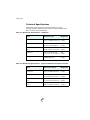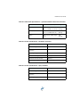
1
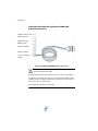
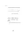
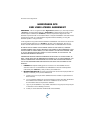
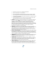
IntelliFlow
User Guide
Part No. 875-0180-000 Rev. C1
This device complies with part 15 of the FCC Rules. Operation is subject to the following two
conditions:
(1) This device may not cause harmful interference, and
(2) this device must accept any interference received, including interference that may cause
undesired operation.
Copyright Notice
Hemisphere GPS Precision GPS Applications
© Hemisphere GPS (2009). All rights reserved.
No part of this manual may be reproduced, transmitted, transcribed, stored in a retrieval system
or translated into any language or computer language, in any form or by any means, electronic,
mechanical, magnetic, optical, chemical, manual or otherwise, without the prior written
permission of Hemisphere GPS.
Trademarks
HEMISPHERE GPS®, the Hemisphere GPS logo, CRESCENT®, ECLIPSETM, COASTTM, e-DIF®,
OUTBACKTM, OUTBACK Guidance®, OUTBACK Guidance CenterTM, OUTBACK STM, OUTBACK
S-LiteTM, OUTBACK S2TM, OUTBACK 360TM. OUTBACK Steering GuideTM, OUTBACK HitchTM,
SATLOC®, the Satloc logo, eDrive®, eDriveTCTM, Just Let GoTM, L-DifTM, BaseLineHDTM,
AerialAceTM, AirStarTM, AirTracTM, GPSteerTM, LiteStar IITM, PocketMaxTM, PocketMax PCTM,
Satloc M3TM, MapStar®, IntelliFlow®, Beeline®, Contour LockTM, StsTM and VectorTM are
proprietary trademarks of Hemisphere GPS. Other trademarks are the properties of their
respective owners.
Patents
The OUTBACK STM and S-LiteTM automated navigation and steering guide system is covered by
U.S. Patents No. 6,539,303 and No. 6,711,501. The OUTBACK HitchTM automated hitch control
system is covered by U.S. Patent No. 6,631,916. The OUTBACK eDriveTC GPS assisted steering
system is covered by U.S. Patent No. 7,142,956. Hemisphere GPS products may be covered by
one or more of the following U.S. Patents:
6,111,549
6,397,147
6,469,663
6,501,346
6,539,303
6,549,091
6,631,916
6,711,501
6,744,404
6,865,465
6,876,920
7,142,956
7,162,348
7,277,792
7,292,185
7,292,186
7,373,231
7,400,956
7,400,294
7,388,539
7,429,952
7,437,230
7,460,942
Other U.S. and foreign patents pending.
Notice to Customers
Contact your local dealer for technical assistance. To find the authorized dealer near you,
call or write us at:
Hemisphere GPS
4110 9th Street S.E.
Calgary, Alberta, Canada T2G 3C4
Telephone number:
Fax number:
E-mail address:
(403) 259-3311
(403) 259-8866
[email protected]
WARRANTY NOTICE
COVERED PRODUCTS. This warranty covers all products manufactured by Hemisphere
GPS and purchased by the end purchaser (the "Products"), unless otherwise specifically and
expressly agreed in writing by Hemisphere GPS.
LIMITED WARRANTY. Hemisphere GPS warrants solely to the end purchaser of the
Products, subject to the exclusions and procedures set forth below, that the Products sold to
such end purchaser and its internal components shall be free, under normal use and
maintenance, from defects in materials, and workmanship and will substantially conform to
Hemisphere GPS's applicable specifications for the Product, for a period of 12 months from
delivery of such Product to such end purchaser (the "Warranty Period"). Repairs and
replacement components for the Products are warranted, subject to the exclusions and
procedures set forth below, to be free, under normal use and maintenance, from defects in
material and workmanship, and will substantially conform to Hemisphere GPS's applicable
specifications for the Product, for 90 days from performance or delivery, or for the balance of
the original Warranty Period, whichever is greater.
EXCLUSION OF ALL OTHER WARRANTIES. The LIMITED WARRANTY shall apply only if
the Product is properly and correctly installed, configured, interfaced, maintained, stored,
and operated in accordance with Hemisphere GPS's relevant User's Manual and
Specifications, AND the Product is not modified or misused. The Product is provided "AS IS"
and the implied warranties of MERCHANTABILITY and FITNESS FOR A PARTICULAR
PURPOSE and ALL OTHER WARRANTIES, express, implied or arising by statute, by course of
dealing or by trade usage, in connection with the design, sale, installation, service or use of
any products or any component thereof, are EXCLUDED from this transaction and shall not
apply to the Product. The LIMITED WARRANTY is IN LIEU OF any other warranty, express or
implied, including but not limited to, any warranty of MERCHANTABILITY or FITNESS FOR A
PARTICULAR PURPOSE, title, and non-infringement.
LIMITATION OF REMEDIES. The purchaser's EXCLUSIVE REMEDY against Hemisphere
GPS shall be, at Hemisphere GPS's option, the repair or replacement of any defective
Product or components thereof. The purchaser shall notify Hemisphere GPS or a
Hemisphere GPS's approved service center immediately of any defect. Repairs shall be made
through a Hemisphere GPS approved service center only. Repair, modification or service of
Hemisphere GPS products by any party other than a Hemisphere GPS approved service
center shall render this warranty null and void. The remedy in this paragraph shall only be
applied in the event that the Product is properly and correctly installed, configured,
interfaced, maintained, stored, and operated in accordance with Hemisphere GPS's relevant
User's Manual and Specifications, AND the Product is not modified or misused. NO OTHER
REMEDY (INCLUDING, BUT NOT LIMITED TO, SPECIAL, INDIRECT, INCIDENTAL,
CONSEQUENTIAL OR CONTINGENT DAMAGES FOR LOST PROFITS, LOST SALES, INJURY
TO PERSON OR PROPERTY, OR ANY OTHER INCIDENTAL OR CONSEQUENTIAL LOSS)
SHALL BE AVAILABLE TO PURCHASER, even if Hemisphere GPS has been advised of the
possibility of such damages. Without limiting the foregoing, Hemisphere GPS shall not be
liable for any damages of any kind resulting from installation, use, quality, performance or
accuracy of any Product.
HEMISPHERE IS NOT RESPONSIBLE FOR PURCHASER'S NEGLIGENCE OR
UNAUTHORIZED USES OF THE PRODUCT. IN NO EVENT SHALL HEMISPHERE GPS BE
IN ANY WAY RESPONSIBLE FOR ANY DAMAGES RESULTING FROM PURCHASER'S OWN
NEGLIGENCE, OR FROM OPERATION OF THE PRODUCT IN ANY WAY OTHER THAN AS
SPECIFIED IN HEMISPHERE GPS'S RELEVANT USER'S MANUAL AND SPECIFICATIONS.
Hemisphere GPS is NOT RESPONSIBLE for defects or performance problems resulting from
(1) misuse, abuse, improper installation, neglect of Product; (2) the utilization of the Product
with hardware or software products, information, data, systems, interfaces or devices not
made, supplied or specified by Hemisphere GPS; (3) the operation of the Product under any
specification other than, or in addition to, the specifications set forth in Hemisphere GPS's
relevant User's Manual and Specifications; (4) damage caused by accident or natural events,
such as lightning (or other electrical discharge) or fresh/salt water immersion of Product; (5)
damage occurring in transit; (6) normal wear and tear; or (7) the operation or failure of
operation of any satellite-based positioning system or differential correction service; or the
availability or performance of any satellite-based positioning signal or differential correction
signal.
THE PURCHASER IS RESPONSIBLE FOR OPERATING THE VEHICLE SAFELY. The
purchaser is solely responsible for the safe operation of the vehicle used in connection with
the Product, and for maintaining proper system control settings. UNSAFE DRIVING OR
SYSTEM CONTROL SETTINGS CAN RESULT IN PROPERTY DAMAGE, INJURY, OR DEATH.
The purchaser is solely responsible for his/her safety and for the safety of others. The
purchaser is solely responsible for maintaining control of the automated steering system at
all times. THE PURCHASER IS SOLELY RESPONSIBLE FOR ENSURING THE PRODUCT IS
PROPERLY AND CORRECTLY INSTALLED, CONFIGURED, INTERFACED, MAINTAINED,
STORED, AND OPERATED IN ACCORDANCE WITH HEMISPHERE GPS'S RELEVANT USER'S
MANUAL AND SPECIFICATIONS. Hemisphere GPS does not warrant or guarantee the
positioning and navigation precision or accuracy obtained when using Products. Products
are not intended for primary navigation or for use in safety of life applications. The potential
accuracy of Products as stated in Hemisphere GPS literature and/or Product specifications
serves to provide only an estimate of achievable accuracy based on performance
specifications provided by the satellite service operator (i.e. US Department of Defense in the
case of GPS) and differential correction service provider. Hemisphere GPS reserves the right
to modify Products without any obligation to notify, supply or install any improvements or
alterations to existing Products.
GOVERNING LAW. This agreement and any disputes relating to, concerning or based upon
the Product shall be governed by and interpreted in accordance with the laws of the State of
Arizona.
OBTAINING WARRANTY SERVICE. In order to obtain warranty service, the end
purchaser must bring the Product to a Hemisphere GPS approved service center along with
the end purchaser's proof of purchase. Hemisphere GPS does not warrant claims asserted
after the end of the warranty period. For any questions regarding warranty service or to
obtain information regarding the location of any of Hemisphere GPS approved service
center, contact Hemisphere GPS at the following address:
Hemisphere GPS
8444 N. 90th Street, Suite 130
Scottsdale, AZ 85258
Phone: 480-348-9919 Fax: 480-348-6370
[email protected]
www.hemispheregps.com
Documentation Feedback
Hemisphere GPS is committed to the quality and continuous improvement of our products
and services. We urge you to provide Hemisphere GPS with any feedback regarding this
guide by writing to the following email address: [email protected]
IntelliFlow User Guide
Contents
Chapter 1
Introducing IntelliFlow
What’s Included . . . . . . . . . . . . . . . . . . . . . . . . . . . . . . 3
Chapter 2
Installing IntelliFlow
Important Safety Considerations . . . . . . . . . . . . . . . . 6
Planning the Installation . . . . . . . . . . . . . . . . . . . . . . . 7
Mounting the Components . . . . . . . . . . . . . . . . . . . . 8
Connecting the Cables (M3) . . . . . . . . . . . . . . . . . . . 11
Connecting the Cables (Flying Flagman) . . . . . . . . 14
Connecting the Spray-Off Relay and Power . . . . . . 16
Calibrating the Pressure Switch (Optional) . . . . . . . 17
Chapter 3
Installing IntelliFlow Dual Rate
Mounting the Components . . . . . . . . . . . . . . . . . . . 20
Connecting the Cables . . . . . . . . . . . . . . . . . . . . . . . 21
Chapter 4
Chapter 5
Activating Your Subscription (M3)
Setting Flow Control Options
Setting IntelliFlow Options (M3) . . . . . . . . . . . . . . . 28
Setting IntelliFlow Dual Rate Options (M3) . . . . . . . 33
Setting IntelliFlow Options (Flying Flagman) . . . . . 38
Chapter 6
Troubleshooting
Common Issues . . . . . . . . . . . . . . . . . . . . . . . . . . . . . 42
Testing the Valve . . . . . . . . . . . . . . . . . . . . . . . . . . . . 45
Chapter A
Appendix
Technical Specifications . . . . . . . . . . . . . . . . . . . . . . 50
v
Updating Firmware . . . . . . . . . . . . . . . . . . . . . . . . . . 53
Wiring Pin-Out Connections . . . . . . . . . . . . . . . . . . . 56
END USER LICENSE AGREEMENT . . . . . . . . . . . . . 64
vi
Chapter 1: Introducing IntelliFlow
What’s Included
1: Introducing IntelliFlow
T
he new Air IntelliFlow® Dual Rate option enables you to spray
variable rate jobs in less time and in fewer trips. It does this by
enabling you to spray two applications at the same time.
The basic IntelliFlow allows you to spray a constant rate or a variable
rate job.
The optional IntelliFlow Dual Rate enables you to:
•
Spray a constant rate and a variable rate job simultaneously.
•
Maintain droplet size when spraying constant Ultra Low Volume
(ULV) rates.
•
Mix two different applications at the end of the spray nozzle on the
same swath.
•
Spray one rate for most of a field and another rate for “spot”
spraying where the crop is in need of special treatment to increase
the yield.
•
Switch back and forth between variable rate and constant rate jobs
as needed.
The Hemisphere GPS flow control solution has proven to be rugged,
efficient, reliable, and most importantly, flexible. The IntelliFlow Dual
Rate option allows you to interface to any valve size and monitor a wide
range of turbine flows. Because you are operating two controllers, you
can independently operate two control valves and two spray-off relays,
while monitoring two flow turbines.
Using the Hemisphere GPS IntelliFlow system is easy. Upload your
prescription maps using MapStar® and select them from the M3’s
cockpit display. Alternatively, you can enter your own flow control
parameters.
2
IntelliFlow User Guide
Figure 1-1: IntelliFlow meter, valve, and controller. Optional IntelliFlow Dual Rate meter, valve, and controller not pictured.
What’s Included
Below is the parts list for the IntelliFlow system. Please check your parts
to make sure you have everything before beginning installation.
Item
Part Number
Qty
IntelliFlow Controller
806-1020-000
1
Spray-Off Relay
900-3040-000
1
Valve/Motor Assembly (2”)
806-1025-000
1
Meter (2”)
806-1025-000
1
Cable (IntelliFlow - M3, AUX, Flow
Meter, Spray-Off Relay)
051-0163-222
1
Cable (IntelliFlow - Flying Flagman, AUX,
Flow Meter, Spray-Off Relay)
051-0204-222
1
Cable (IntelliFlow - Motor/Valve)
054-0110-222
1
User Guide
875-0180-000
1
3
1: Introducing IntelliFlow
Item
Part Number
Qty
IntelliFlow Controller
806-1020-000
2
Spray-Off Relay
900-3040-000
2
Valve and Motor Assembly (2”)
806-1025-000
1
**Valve and Motor Assembly (1/2”)
710-0060-000
1
*Valve and Motor Assembly (1”)
806-1032-000
1
Flow Meter (2”)
900-3026-000
1
**Flow Meter (1/2”)
750-0046-000
1
*Flow Meter (3/4”)
710-0059-000
1
**Cable (Ultra-Low Volume Adaptor)
051-0173-000
1
Cable (IntelliFlow Dual Rate - M3, AUX,
Flow Meter, Spray-Off Relay)
051-0170-000
1
Cable (IntelliFlow - Motor/Valve)
054-0110-222
2
Cable (IntelliFlow - Power)
054-0101-000
2
Pressure Switch, Aircraft
075-0035-222
2
10 Amp Circuit Breaker
424-0004-222
2
User Guide
875-0180-000
1
Notes:
*Available with 1” Intelliflow Dual Rate Kit.
**Available with 1/2” Ultra-Low Volume Intelliflow Dual Rate Kit.
4
Chapter 2: Installing IntelliFlow
Important Safety Considerations
Planning the Installation
Mounting the Components
Connecting the Cables (M3)
Connecting the Cables (Flying Flagman)
Connecting the Spray-Off Relay and Power
Calibrating the Pressure Switch (Optional)
2: Installing IntelliFlow
Important Safety Considerations
Warning! Please read all installation instructions and warnings
BEFORE beginning the installation. FAILURE TO DO SO MAY
CAUSE IRREVERSIBLE DAMAGE TO YOUR SYSTEM.
For trouble-free operation and maintenance of your IntelliFlow system,
please adhere to the following recommendations.
1.
Avoid using the IntelliFlow system in environmental conditions
above or below the specified operating temperatures.
2.
When flying under adverse conditions, cover the motor head with a
water-resistant canvas to avoid water and/or chemicals from
seeping into the controller or motor.
3.
Wash the hopper/boom system thoroughly and methodically after
spray sessions to avoid gumming up the flow turbine unit.
Warning! If you do not maintain your system and find the flow
turbine unit gummed up, you may have to remove the unit and
clean it on the bench. This requires disassembling the unit and
reassembling it.
4.
When using highly corrosive products, protect the valve stem by
lubricating it with a few drops of pneumatic turbine lubricating oil
or, if not available, low-viscosity lubricating oil every 20 to 30 hours
of spray time. This will avoid gumming and/or chemical corrosion
buildup around valve stem and/or gland sealing components.
Tip! Apply penetrating oil, if required. Use products such as WD-40 or
any quality penetrating oil before lubricating.
5.
Do not tighten the valve stem gland-retaining nut unless you know
how it is sealed. Any incorrect adjustment to the tension of the
gland-retaining nut can adversely change the torque required to
rotate the valve stem. This will cause the motor valve transmission
and/or motor to over work, possibly causing damage.
Warning! If the valve stem starts to gum-up, the motor valve
will not be able to respond to the IntelliFlow commands
correctly. A tight valve stem can cause excessive current
through the power IC chip inside the IntelliFlow controller.
6
IntelliFlow User Guide
Planning the Installation
To install the IntelliFlow system:
•
mount the flow control components,
•
connect the cables,
•
connect the spray-off relay and power, and
•
calibrate the pressure switch (optional).
Required Tools
Installing IntelliFlow requires the following tools:
•
electric drill and 3/16” and 5/32” drill bits
•
hacksaw
•
thread sealant to prevent leakage
•
hose or flange clamps (12)
•
support straps (1 - 2). A stainless wrap-around strap and supporting
piece is recommended.
Required Power Supply
IntelliFlow requires an 11 - 32 Volt power supply.
Warning! Power connections must be properly grounded. See
Figure 2-5 on page 16 for recommended ground points.
7
2: Installing IntelliFlow
Mounting the Components
Install the following components before connecting the cables:
•
the IntelliFlow controller
•
the spray-off relay
•
the flow meter and motor/valve assembly
•
the power and run/dump switches
Installing the IntelliFlow Controller
Install the controller in an available space on the aircraft. For example,
in a compartment above the boom.
Note: If using IntelliFlow Dual Rate, you will install a second controller.
See Chapter 3 for details.
To install the controller
1.
Use the controller to mark your mounting location.
2.
Use a 3/16” drill bit to drill the mounting holes.
3.
Mount the controller to the aircraft using #10-32 fasteners.
Installing the Spray-Off Relay
Mount the spray-off relay next to the controller.
To install the spray-off relay.
1.
Use the relay to mark your mounting locations.
2.
Use a 5/32” drill bit to drill the mounting holes.
3.
Use 2 #8-32 screws to mount the relay to the aircraft.
Installing the Flow Meter and Valve Assembly
Install the flow meter and motor/valve assembly in the existing boom
supply tube on the aircraft. The figure below shows the recommended
configuration of IntelliFlow’s flow meter and motor/valve assembly.
8
IntelliFlow User Guide
Other configurations are possible, but see the Caution note on the next
page.
Boom
Direction of flow
Aircraft
bypass
valve
Strainer
Meter
10”
minimum
Motor/
valve
Figure 2-1: IntelliFlow meter and motor/valve assembly.
Note: If using IntelliFlow Dual Rate, you will install a second flow meter
and motor/valve assembly next to the first one. See Chapter 3 for
details.
Caution! Install the flow meter before the valve to avoid
turbulence around the flow meter.
If you cannot install the units in the recommended configuration due
to physical limitations in your aircraft, you may invert the units. To
reduce turbulence, maintain the following minimum hose length-todiameter ratios:
•
hose between strainer and flow meter (10:1)
•
hose between flow meter and motor/valve assembly (5:1)
9
2: Installing IntelliFlow
To install the flow meter and motor/valve
1.
Measure and cut the hoses needed to connect the strainer to the
flow meter, the flow meter to the motor/valve assembly, and the
motor/valve assembly to the boom.
2.
Connect the hoses using hose clamps. Use two clamps at each
connection point (refer to Figure 2-1. ).
Warning! Place the meter at least 10” from the valve to
minimize turbulence around the flow meter. See the Caution
note above.
3.
Attach the IntelliFlow assembly to the boom supply plumbing.
Note: The completed IntelliFlow assembly will be installed in the
middle of your boom supply tube.
4.
Install one or two support fittings from the belly of the aircraft close
to the valve and flow meter.
Warning! Do not connect fittings directly to the valve or meter.
Use a stainless wrap-around strap and supporting piece.
Installing the Power and Run/Dump Switches
Install the Power and Run/Dump switches so that they are accessible to
the pilot while flying.
Note: You may need to disassemble the wires on the switches to place
the switches in the panel depending on the desired assembly and
drilling locations.
To install the switches.
1.
Install the switches in the instrument panel in the cockpit.
2.
Connect the switch circuit breaker to the master bus. See Figure 2-5
on page 16.
10
IntelliFlow User Guide
Connecting the Cables (M3)
Use the following diagram to connect the cables to the flow control
components, M3, and power supply. A detailed diagram of the relay kit
installation needed for variable rate is shown on the next page.
Warning! Avoid shorts to the ground which will damage the
IntelliFlow control unit and/or motor control unit. Check the
grounding cable and lugs.
Do not coil or pinch cables. This will introduce noise into the system
and/or destroy the cable.
Secure all cables to avoid the effects of excessive vibration.
Do not place stress on the cable connectors.
Store excess cable length with a minimum 6-inch bend radius.
Avoid high-temperature exposure (exhaust, manifold, etc.) when
routing cables.
Avoid running cables where they will interfere with normal operation of
the aircraft.
Avoid placing cables close to sources of interference.
11
2: Installing IntelliFlow
M3 Controller
Boom
pressure
switch**
GPIO
Power
11 - 32 VDC
10 Amp breaker
IntelliFlow Controller
(806-1020-000)
Power
Motor
Aux
VRC/COM 1
*Spray
relay
Pump
*Refer to “Connecting the
Spray-Off Relay and
Power”
Manual override
bypass switch
Boom
Meter
10”
minimum
Motor/valve
assembly
Figure 2-2: IntelliFlow-M3 cable connections.
Note: Cable connection details for the spray-off relay and power are
detailed in Figure 2-5 on page 16.
** See Figure 2-3 on page 13 for the Boom Pressure Switch wiring
details.
12
IntelliFlow User Guide
(075-0035-222)
Figure 2-3: Boom Pressure Switch Setup
13
2: Installing IntelliFlow
Connecting the Cables (Flying Flagman)
Use the following diagram to connect the cables to the flow control
components, Flying Flagman, and power supply.
Figure 2-4: *IntelliFlow-Flying Flagman cable connections.
14
IntelliFlow User Guide
Warning! •Avoid shorts to the ground which will damage the
IntelliFlow control unit and/or motor control unit. Check the
grounding cable and lugs.
•
Do not coil or pinch cables. This will introduce noise into the
system and/or destroy the cable.
•
Secure all cables to avoid the effects of excessive vibration.
•
Do not place stress on the cable connectors.
•
Store excess cable length with a minimum 6-inch bend radius.
•
Avoid high-temperature exposure (exhaust, manifold, etc.) when
routing cables.
•
Avoid running cables where they will interfere with normal
operation of the aircraft.
•
Avoid placing cables close to sources of interference.
Notes:
Connections for Cable 05-F-2006:
Red wire - Pin 11 of DB25 connector
Black wire - Pin 12 of DB25 connector
Do not connect cable shield to anything.
The Micronair flow meter can be used without the Micronair monitor.
Use Cable 051-0208-222 in this case.
The system bypass switch, part number 075-3019-222, comes with Cable
054-0110-222.
Set the pressure switch to operate between 12 and 15 psi.
15
2: Installing IntelliFlow
Connecting the Spray-Off Relay and Power
Use the following diagram to connect the spray-off relay and power.
Aircraft bus
24V
Fuse holder
Cable
(051-0211-222)
Cable to controller
(051-0210-222)
Brake control
interface box
10 Amp
CB
Aircraft
ground
Aircraft pump/
fan brake
Diode 100 PIV 3 Amps
DNTI P/N 280-4018-222
Aircraft ground
Manual switch
Figure 2-5: Spray-off relay and power connections.
Note: The individual wires for Cable 051-0211-222 are 15’ long.
16
IntelliFlow User Guide
Calibrating the Pressure Switch (Optional)
Use the following formula to calibrate the pressure switch, if using one.
Switch Pressure = 50% of Minimum Spray Boom Pressure
For example, if the minimum boom spray pressure is 20 pounds, adjust
the pressure switch to 10 pounds.
To calibrate the pressure switch
1.
Remove upper rubber stop on the pressure switch.
2.
Adjust the Allen screw head inside the top of the switch.
3.
Use a multi-meter or low voltage (1.5 D.C.) bulb to indicate when
switch contacts are closed.
Note: The switch is N/O (Normally Open); The contacts will close when
the required pressure is correct.
17
2: Installing IntelliFlow
18
Chapter 3: Installing IntelliFlow
Dual Rate
Mounting the Components
Connecting the Cables
3: Installing IntelliFlow Dual Rate
T
o install the IntelliFlow Dual Rate system, follow the installation
instructions for IntelliFlow in Chapter 2 with the following
exceptions:
•
Mount a second controller and a second flow meter and motor/
valve assembly.
•
Follow the instructions for connecting the cables for the IntelliFlow
Dual Rate in this section.
It is very important that you follow the instructions listed in Chapter 2
under:
•
Important Safety Considerations
•
Planning the Installation
Mounting the Components
The IntelliFlow Dual Rate system uses a second controller and a second
flow meter and motor/valve assembly.
Follow the instructions in Chapter 2 to mount the second set of
components.
20
IntelliFlow User Guide
Connecting the Cables
Use the following diagram to connect the cables to the flow control
components, M3, and power supply. A detailed diagram of the relay kit
installation needed for variable rate is shown in “Installing IntelliFlow”
in Figure 2-5 on page 16.
Power
11-32 VDC
10 Amp breaker
M3 Controller
GPIO
Boom
pressure
switch
Controller
(806-1020-000)
Power
Motor
Aux
VRC/COM 1
Power
11-32 VDC
10 Amp breaker
Boom
pressure
switch
Power
Motor
Aux
VRC/
COM 1
Cable 054-0110-222
Pump
Spray
relay
Pump
Manual
override
bypass
switch
Meter
Motor/
valve
Controller
(806-1020-000)
Cable 051-0170-000
Spray
relay
Manual
override
bypass
switch
Meter
Motor/
valve
To spray boom
Figure 3-1: IntelliFlow Dual Rate cable connections.
21
3: Installing IntelliFlow Dual Rate
22
Chapter 4: Activating Your
Subscription (M3)
4: Activating Your Subscription (M3)
Y
ou must activate your subscription to access the variable rate and/
or IntelliFlow Dual Rate options if using the M3. Without activating
your subscription, you will only be able to fly single hopper,
constant rate jobs.
To activate your subscription
1.
Select Setup > Setup > Setup > Subscription Authorizations
to access the Subscription Authorizations screen.
24
IntelliFlow User Guide
2.
From the Subscription Authorizations screen, select the feature
you want to activate and enter your subscription number.
a.
In the Select Subscription field, select the feature you are
activating from the drop-down menu.
b.
In the Enter CS Subscription # field, enter your subscription
number.
Note: If you did not receive a subscription number at your time of
purchase, please call Hemisphere GPS Technical Support at 480-3489919.
25
4: Activating Your Subscription (M3)
c.
4.
Verify that you entered the correct subscription number by
selecting Accept Subscription #.
Repeat the above steps for each feature you wish to activate.
26
Chapter 5: Setting Flow Control
Options
Setting IntelliFlow Options (M3)
Setting IntelliFlow Dual Rate Options (M3)
Setting IntelliFlow Options (Flying Flagman)
5: Setting Flow Control Options
Setting IntelliFlow Options (M3)
The AirTrac M3 automatically detects which supported flow control
system is connected. If using IntelliFlow, a “Single IntelliFlow Detected”
message appears at the top of your AirTrac Setup screen.
With IntelliFlow, you can fly either a constant or variable rate spray job.
Variable rate spray jobs require you to upload a prescription map.
This section covers setting flow control options for constant rate or
variable rate spray jobs.
To set the flow control options
1.
Turn on the M3 system. The AirTrac Setup screen appears:
The screen displays the following message indicating installation
was successful: “Controller FOUND.”
Note: If the “Controller NOT FOUND” message appears, click the
RESET button to search for installed controllers.
28
IntelliFlow User Guide
2.
From the AirTrac Setup screen, select SETUP > Flow Control to
access the Flow Control Setup screen.
29
5: Setting Flow Control Options
3.
From the Flow Control Setup screen, set your basic flow control
options.
Controller type is
automatically
detected.
Select Setup
to access the
Advanced
Flow Control
Setup screen
for:
Select the type of
spray job constant or
variable rate.
Select application
type: liquid or dry.
- meter
calibration
Enter a target rate
if flying a constant
rate spray job.
- flow lead
time (on/off),
and
Import
Prescription Map
if flying a variable
rate spray job.
*Enter beginning
volume
- valve
testing (see
Appendix).
Reset volume
when refilling
hopper.
Reset total area
when starting a
new spray job.
30
IntelliFlow User Guide
4.
Select Setup to open the Flow Control Advanced Setup screen.
Select to set
controller
parameters.
Lead time
represents
how early the
flow control will
react to reach the
proper rate at the
proper location.
Adjust defaults if
necessary.
If you need to test your valve,
.
see Troubleshooting.
5.
Set the controller parameters from the Flow Controller
Parameters screen.
31
5: Setting Flow Control Options
Set Auto Boom
to YES.
Enter the
factory
calibration
factor from
the meter (k
factor) - 3%.
Enter your target
rate.
Press to reset
the hopper
volume.
32
IntelliFlow User Guide
Setting IntelliFlow Dual Rate Options (M3)
The AirTrac M3 automatically detects which supported flow control
system is connected. If using IntelliFlow Dual Rate, a “IntelliFlow Dual
Rate Detected” message appears at the top of your AirTrac Setup
screen.
With IntelliFlow Dual Rate, you can set job spray options for two
different controllers - a primary controller and a secondary controller.
•
The primary controller controls your primary hopper. The primary
hopper allows you to set a constant target rate.
•
The secondary controller controls the secondary hopper. The
secondary hopper allows you to set a variable target rate using a
prescription map.
The two-controller system allows you to fly a constant and variable rate
spray job simultaneously. For example, perhaps you need to spray one
rate for most of the field, but spray a different rate for certain areas. You
can set your primary target rate using the primary controller and
designate the areas needing heavier spraying by using a prescription
map with the secondary controller.
IntelliFlow Dual Rate also provides you with the flexibility to switch back
to a single, constant or variable rate job by disabling the secondary
hopper from the main flow control setup screen.
This section covers:
•
Setting flow control options for dual controllers (constant and
variable rate spray jobs)
•
Disabling the secondary controller for single constant or variable
rate jobs
33
5: Setting Flow Control Options
To set flow control options for dual controllers (constant and
variable rate)
1.
Turn on the M3 system. The AirTrac Setup screen appears:
The screen displays the following messages indicating installation
was successful:
•
“IntelliFlow Dual Rate Detected” in the top left corner.
•
“Controller FOUND” at the bottom of the screen.
Note: If the “Controller FOUND” message does not appear, click the
RESET button to search for installed controllers.
34
IntelliFlow User Guide
2.
From the AirTrac Setup screen, select SETUP > Flow Control to
access the Flow Control Setup screen.
3.
From the Flow Control Setup screen, set your flow control
options for the primary hopper.
Controller type is
automatically
detected.
Select Setup > Set
Controller
Parameters to set
controller
parameters for the
secondary hopper.
Select application
type: liquid or dry.
Enter a target rate for
the primary hopper.
Import a Prescription
Map for the secondary
hopper. This will
control your target
rate.
Enter beginning
volume for the
Reset Total Area
primary hopper. Volume Reset volume for
hopper 1 here. The when starting a
for the secondary
reset volume button new spray job.
hopper
is set in the IntelliFlow for the secondary
Dual Rate Controller hopper is in the
Parameters screen.
IntelliFlow Dual
Rate Controller
35
Set Mode to DUAL.
SINGLE will disable
the secondary
controller.
5: Setting Flow Control Options
Notes:
If using the IntelliFlow Dual Rate system, you must import the
Prescription Map for the secondary controller here on the main Flow
Control Setup screen.
In the Mode field, AUTO automatically searches for and finds the
controller type you have connected (if supported). Selecting DUAL will
speed up initialization. SINGLE will disable the secondary controller, so
do not select this if flying a two-controller job.
4.
Select Setup > Set Controller Parameters to access the
IntelliFlow Dual Rate Controller Parameters screen.
36
IntelliFlow User Guide
5.
Set the controller parameters for Controller 2 from the IntelliFlow
Dual Rate Controller Parameters screen. Notice that each
controller has its own set of spray options.
Set Auto Boom to
YES for Dual Flow.
Notice the Target Rate
button is grayed out for
the secondary controller.
Enter the
factory
calibration
factor from the
meter (k factor)
- 3%.
Set volume
for hopper 2
here.
Each hopper has
its own Reset
Volume button.
The secondary controller
requires a prescription
map. You cannot select a
prescription map from
this screen. you must
return to the Flow
Control Setup screen to
import a prescription
map.
Warning! If, while using the secondary controller, the Target
Rate field displays “N/A,” you must return to the Flow Control
Setup screen to import a prescription map.
Notice that the Target Rate button is grayed out for the secondary
controller. You cannot select a prescription map from this screen. you
must return to the Flow Control Setup screen to import a prescription
map.
To set flow control options for a single controller (constant or
variable rate)
1.
Follow steps 1 - 3 in the previous section to set your flow control
options for the primary hopper.
2.
In the Flow Control Setup screen’s Mode field, select SINGLE.
37
5: Setting Flow Control Options
Setting IntelliFlow Options (Flying Flagman)
The Flying Flagman flow control options are set from the main Flow
Menu. Before flying a spray job, you must set:
•
the beginning hopper volume,
•
the target spray rate, and optionally, the turnaround delay,
•
the meter calibration factor, and
•
IntelliFlow as the desired controller
Warning! Before setting IntelliFlow Options for the Flying
Flagman, you must select the desired units in the Scale menu.
1.Open the Flow Menu.
2.Enter the beginning hopper volume.
a.
From the Flow Menu, select Load Tank. The TANK SIZE
screen appears:
b.
Press Enter to select, or the arrow key to enter a different
number.
Note: The remaining volume amount is displayed on the Run screen by
REM.
38
IntelliFlow User Guide
3.
Enter your target flow rate.
a.
From the Flow Menu, select Set App Rate. The FLOW RATE
screen appears:
b.
Press Enter to select, or the arrow key to enter a different
number.
Note: The flow rate is displayed on the Run screen by APP or
APPLICATION FLOW RATE
4.
(Optional) Change the turnaround delay (TAD). The TAD is the
additional reversal time (in milliseconds) given to the IntelliFlow
motor when reversing direction. The default rate is 40 ms.
a.
To enter a turnaround delay, enter “0” for the rate in the FLOW
RATE screen (step 3, above). The FLOW TAD screen appears:
b.
Press Enter to select, or the arrow key to enter a different
number.
Note: The TAD must be between 20 and 70 ms.
39
5: Setting Flow Control Options
5.
Set the calibration factor.
a.
From the Flow Menu, select Set Cal Factor. The FLOW
CALFAC screen appears:
b.
Press Enter to select, or the arrow key to enter a different
number.
Note: The calibration factor is the factory calibration number found on
the meter minus 3%.
6.
Select IntelliFlow as your controller.
a.
From the Flow Menu, select Select Device. The FLOW
SELECT screen appears:
b.
Press Enter to select, or the arrow key if IntelliFlow is not the
controller shown here.
40
Chapter 6: Troubleshooting
Common Issues
Testing the Valve
6: Troubleshooting
Common Issues
Common issues addressed in this section include:
•
No Power When Initialize System
•
Valve Does Not Open
•
Meter Does Not Work
•
Motor Does Not Rotate
•
Flow Data Is Not Displayed on the Run Screen
For further help, call Hemisphere GPS Technical Support.
No Power When Initialize System
After turning on the power, wait 10 to 15 seconds for the IntelliFlow
controller microprocessor to initialize. The microprocessor startup can
be heard with a low beep if ambient noise is low.
If there is no power to the system:
1.
Ensure that there is power to the IntelliFlow controller and
controller fuse.
2.
Check the fuse.
Warning! Disconnect the power source from IntelliFlow
controller when checking the fuse.
a.
Remove the fuse from the IntelliFlow controller and inspect the
fuse for signs of over-current
Note: Voltage sent to the Normal/bypass switch from the IntelliFlow
controller does not pass through the 10 Amp fuse on the controller. This
is a security feature in case the IntelliFlow controller malfunctions,
allowing the control valve motor to rotate to the open position.
b.
Check for other fuse problems:
•
aircraft battery state (common problem)
•
aircraft-IntelliFlow cable installation
42
IntelliFlow User Guide
3.
•
aircraft-IntelliFlow grounding connections
•
aircraft battery charging system (e.g., alternator, regulator,
etc.)
Check all wiring connections and terminal strips
Warning! Avoid shorts to ground which will damage the
IntelliFlow controller and/or motor controller. Check the
IntelliFlow controller grounding cable and grounding lugs.
Valve Does Not Open
Perform a valve test (see Testing the Valve in this chapter). If you have
power to the system, but the valve does not open:
1.
Ensure that the override switch is in the normal position.
2.
Ensure that the pressure switch is normally open and working
properly.
Note: The valve will not move if the pressure switch is stuck in the
closed position.
a.
Remove the Aux switch I/O connector plug, where the pressure
switch connects, from the IntelliFlow controller.
b.
Reset the system and check for normal operation. Normal
operation indicates a problem with the pressure switch.
Meter Does Not Work
If the valve works, but the meter still does not work, try the following.
1.
Manually spin meter and check for the system response.
2.
Verify that the pressure switch is triggered. The system will not
respond to the meter if it is not triggered.
3.
Check for the general working condition of the controller if a spare
transducer is available.
a.
Connect the transducer sensor to the cable that is normally
connected to the flow turbine unit.
43
6: Troubleshooting
b.
Generate pulses by passing or tapping an iron object over the
pick-up point of the sensor.
Note: These simulated pulses are not sufficient for accurate testing, but
are sufficient for checking cables, IntelliFlow control unit I/O ports,
interface between the IntelliFlow control unit and the M3, and general
display operation. Adjust for 200 Hz square wave, amplitude close to
150 mv, 0 offset. If a simple function generator is available, connect it to
the sensor connector to produce pulses.
Warning! Do not install fuses greater than 10 Amps for the
IntelliFlow control unit. A greater fuse value will cause internal
damage to the IntelliFlow control unit.
1.
Check the system for gummed up components. Turbine blades and
the valve stem are susceptible to problems if proper maintenance
isn’t performed.
2.
Check that the motor, controller, sensor unit, and connector do not
have water or chemicals inside.
Motor Does Not Rotate
1.
Check the voltage across the flow control sensor contacts if the
motor does not rotate. The voltage should be logic 5 VDC. If the
voltage across the sensor is 0 VDC or less than 4 VDC, check the
sensor cabling and/or sensor.
2.
Disconnect pressure sensor connections if the operation step 3,
above is normal.
•
Maintain power to the IntelliFlow control unit.
•
Observe the flow status/flow position.
•
Toggle NORMAL/BYPASS to bypass the position. The motor
will fully open.
44
IntelliFlow User Guide
Flow Data Is Not Displayed on Run Screen
•
(Flying Flagman) If the DISPLAY, 7 Run Screen is blank or the
status does not change, it is most likely a defective IntelliFlow
control unit or a serial port problem.
•
(M3) If the Flow Control screen data is blank or incorrect, it is most
likely due to incorrect setup. See Chapter 5 for further information.
Testing the Valve
The valve test procedures for both the M3 and the Flying Flagman are
described in this section.
Testing the Valve (M3)
Perform the valve test directly from the M3 menu. You can test:
•
if the valve opens and closes
•
if the valve turnaround delay (TAD) is set correctly
•
if the spray-off relay is working
Warning! When testing the valve, speed must be less than 11
m.p.h.
45
6: Troubleshooting
To test the valve
Note: If using IntelliFlow Dual Rate, you can test the valves and sprayoff relays for the primary and secondary controllers independently. The
controller you are testing will be displayed on the screen.
1.
From the Flow Control Advanced Setup menu, select Test
Valve.
46
IntelliFlow User Guide
2.
Select the valve open/close time in ms.
Valve positions are
shown here
Controller 1 selected
Test the spray-off relay
3.
Press the Open and Close buttons. Notice the valve position
numbers.
4.
Test the spray-off relay, if necessary. The unit will stay active for 5
ms.
47
6: Troubleshooting
Testing the Valve (Flying Flagman)
1.
Enter Display, 7 to open the Diagnostic Info screen. Note the
valve position number.
Volume applied
(LPM)
Application rate
(LPH)
Status:
64 - initialization
44 - no spray
C4 - spray
E4 - motor moved
Turbine pulses
since initialization
*Valve position number:
3250 - fully closed
2650 - 1/4 open
2050 - 1/2 open
1550 - 3/4 open
1050 - fully open
(*+/- 50)
Note: The valve position values can change according to valve type and
size.
2.
Press the Run Screen key to exit this screen.
48
Chapter A: Appendix
Technical Specifications
Updating Firmware
Wiring Pin-Out Connections
A: Appendix
Technical Specifications
Mechanical, power, and environmental specifications for the
Hemisphere GPS IntelliFlow system and the optional IntelliFlow Dual
Rate controller are provided below.
Table A-1: Mechanical Specifications - IntelliFlow
Item
Dimensions (in.)
Weight (lbs)
IntelliFlow Controller
11.7 L x 6.70 W x 2.38 H
(29.7 L x 17.0 W x 6.03 H cm)
4.00
(1.8 kg)
Spray-Off Relay
6.00 L x 2.60 W x 1.63 H
(4.1 H x 15.2 L x 6.6 W cm)
5.00
(2.3 kg)
Valve and Motor Assembly
(2”)
5.50 L x 3.75 W x 10.00 H
(25.4 H x 14.0 L x 9.5 W cm)
14.25
(6.5 kg)
Meter (2”)
4.75 L x 3.25 W x 4.75 H
(12.1 H x 12. 1 L x 8.3 W cm)
4.00
(1.8 kg)
Cables
Not provided.
Cable lengths vary.
3.50
(1.6 kg)
Table A-2: Mechanical Specifications - Optional IntelliFlow Dual Rate Controller
Item
Dimensions (inches)
Weight (lbs)
IntelliFlow Dual Rate
Controller
11.70 L x 6.70 W x 2.38 H
(29.7 L x 17.0 W x 6.0 H cm)
4.00
(1.8 kg)
Spray-Off Relay
6.00 L x 2.60 W x 1.63 H
(15.2 L x 6.6 W x 4.1 H cm)
5.00
(2.3 kg)
Valve and Motor Assembly
(2”)
5.50 L x 3.75 W x 10.00 H
(12.7 L x 9.5 W x 25.4 H cm)
14.25
(6.5 kg)
Valve and Motor Assembly
(1/2”)
4.00 L x 4.00 W x 7.00 H
(10.2 L x 10.2 W x 17.8 H cm)
4.25
(1.9 kg)
50
IntelliFlow User Guide
Table A-2: Mechanical Specifications - Optional IntelliFlow Dual Rate Controller
Item
Dimensions (inches)
Weight (lbs)
Meter (2”)
4.75 L x 3.25 W x 4.75 H
(12.1 L x 8.3 W x 12.1 H cm)
4.00
(1.8 kg)
Meter (3/4”)
4.00 L x 2.13 W x 3.75 H
(12.1 L x 5.4 W x 9.5 H cm)
2.00
(0.9 kg)
Cables
Not provided. Cable lengths
vary.
7.00
(3.2 kg)
Table A-3: Power Specifications - IntelliFlow Controller
Specification
Description
Inverse Voltage Protection
Yes
Over Current and/or Short Circuit
Protection
Yes
Operating Voltage
24 - 36 VDC
Maximum Working Current
10 Amps
Maximum Transient Current
10 Amps
Nominal Operating Current Range
0.3 to 6 Amps
Table A-4: Power Specifications - Spray-Off Relay
Specification
Description
Inverse Voltage Protection
Yes
Over Current and/or Short Circuit
Protection
Yes
Operating Voltage
11 - 60 VDC
51
A: Appendix
Table A-4: Power Specifications - Spray-Off Relay
Maximum Working Current
7 Amps
Maximum Transient Current
10 Amps
Nominal Operating Current Range
0.1 to 6 Amps
Table A-5: Environmental Specifications
Operating Temperature
-4 to + 140 F (-20 to +60 C)
Storage Temperature
-40 to + 176 F (-40 to +80 C)
Humidity
95% non-condensing
Resistance
Dust and Water
Vibration and Shock
52
IntelliFlow User Guide
Updating Firmware
This section describes the procedure to update firmware for both the
M3 and the Flying Flagman.
Updating Firmware (M3)
To update firmware from the M3
1.
Copy the firmware update files to your PCMCIA card.
2.
Place the PCMCIA card in the M3 controller.
3.
Select Load New Program from the TAD/Diagnostics &
Troubleshooting screen.
Note: GPS speed must be less than 5 m/s and the system must
recognize the *software version for the Load New Program button to
be selectable.
*The software version must be more recent than 1pF or 1rF.
53
A: Appendix
4.
Select YES or NO to upload or cancel upload.
5.
A status message displays, “Please Wait, Rebooting IntelliFlow.”
The following screen then appears.
54
IntelliFlow User Guide
Updating Firmware (Flying Flagman)
To update firmware from the Flying Flagman
1.
Copy the firmware update files to your PCMCIA card.
Warning! The PCMCIA card must be formatted properly (DOS).
An incorrectly formatted card may corrupt your system and
require you to use the cable download method to restore your
files.
2.
Place the PCMCIA card in the Flying Flagman controller.
3.
From the main Setup menu, select Flow > New Flow Program.
4.
Press Enter to abort the download process or wait to see the next
screen.
5.
To download the new software from the PCMCIA card, please note
that if the red LED light on the upper right corner of the shift key is
illuminated, you press the Shift key twice and then press the Esc
key.
If the red LED light on the upper right corner of the shift key is not
illuminated, you press the Shift key once and then press the Esc
key. The keys must be press sequentially, not simultaneously, to
initiate the download process.
55
A: Appendix
6.
Wait while the system downloads the IntelliFlow update.
7.
Verify that the update was successful. If so, the following screen
appears:
If not, the following error screen appears:
8.
Reboot your system for the update to take effect.
Wiring Pin-Out Connections
This section provides additional detail for cable wiring pin-out
connections.
•
Cable 051-0163-222 (IntelliFlow - Spray-Off Relay, AUX, M3, and
Flow Meter)
•
Cable 054-0110-222 (IntelliFlow - Motor/Valve)
•
Cable 051-0170-000 (IntelliFlow Dual Rate - Spray-Off Relay, AUX,
M3, and Flow Meter)
•
Cable 051-0204-222 (Flying Flagman GMU)
•
Cable 051-0173-000 (IntelliFlow Dual Rate - Ultra Low Volume
Adapter)
56
IntelliFlow User Guide
Cable 051-0163-222 (IntelliFlow - Spray-Off Relay,
AUX, M3)
Connection diagram for the IntelliFlow, Spray-Off Relay, AUX, M3 and
DNTI flow meter.
BLACK, 22AWG
RED, 22AWG
Hopper Hopper +
BLU/WHT, 22AWG Flow1 RED/WHT, 22AWG Flow1 +
BLK/WHT, 22AWG GRD
ORG/WHT, 22AWG Flow2 +
WHT, 22AWG
Flow1 +
Shield
BLU/WHT, 22AWG
RX M3
TX M3
BLK/WHT, 22AWG
GRD
Shield
RED/WHT, 22AWG
GRD
BLU/WHT, 22AWG
12+
BLK/WHT, 22AWG
ORG/WHT, 22AWG
RTS
CTS
Figure A-1: Cable 051-163-222 wiring pin-out connections.
57
A: Appendix
Cable 054-0110-222 (IntelliFlow - Motor/Valve)
The wiring pin-out connections for the boom pressure switch (SW1) are
shown below.
12.5 ft
5.5 ft
Switch, 10A,
IntelliFlow
DPDT
Motor/valve
7343K82
(075-3019-222)
Detail B
Label
(677-1024-222)
Figure A-2: Cable 054-0110-222.
Shield
Bypass switch
GRN
ORG
WHT
IntelliFlow
motor valve
BLK
ORG
Note
2PL
WHT/BLK stripe
GRN/BLK stripe
BRN/BLK stripe
N/C
BLU
BLK
WHT
RED
P4 label
Figure A-3: Wiring pin-out details for SW1.
58
IntelliFlow User Guide
Cable 051-0170-000 (IntelliFlow Dual Rate - Spray-Off
Relay, AUX, M3, and Flow Meter)
Figure A-4: Cable 051-0170-000 pin-out connections.
59
A: Appendix
Cable 051-0204-222 (Flying Flagman GMU AUX
Switch Connections)
1 Swath advance (red)
2 Swath decrease
3 Break (orange)
4 Mark (green)
5 Resume (brown)
6 Hopper (white)
7 Circuit complete
(black)
Figure A-5: GMU-1/TNG AUX switch connections.
Warning! DO NOT connect the black ground wire to the aircraft
ground or shield of the cable.
DO NOT allow the black ground wire to touch any part of the fuselage.
The black ground wire is the logic return ground for the GMU’s remote
switch functions. The black ground wire is used as the common return
for the other remote switch wires.
See the following figure for an example.
60
IntelliFlow User Guide
RED wire
from GPU
Swath
Adv
button
BLACK wire
ORANGE wire
from GMU
Break
Button
BLACK wire
WHITE wire
from GMU
BLACK wire
Spray on/off
RED wire from
IntelliFlow cable
GMU aux cable
Pressure switch
BLACK wire from
IntelliFlow cable
Figure A-6: GMU AUX switch connection example.
61
A: Appendix
Cable 051-0173-000 (Ultra-Low Volume Adapter)
Figure A-7: Cable 051-0173-000.
Figure A-8: Cable 051-0173-000 wiring pin-out connections.
62
End User License
Agreement
End User License Agreement
HEMISPHERE GPS
END USER LICENSE AGREEMENT
IMPORTANT - This is an agreement (the "Agreement") between you, the end purchaser
("Licensee") and Hemisphere GPS Inc. ("Hemisphere") which permits Licensee to use
the Hemisphere software (the "Software") that accompanies this Agreement. This
Software may be licensed on a standalone basis or may be embedded in a Product. Please
read and ensure that you understand this Agreement before installing or using the
Software Update or using a Product.
In this agreement any product that has Software embedded in it at the time of sale to the
Licensee shall be referred to as a "Product". As well, in this Agreement, the use of a
Product shall be deemed to be use of the Software which is embedded in the Product.
BY INSTALLING OR USING THE SOFTWARE UPDATE OR THE PRODUCT, LICENSEE
THEREBY AGREES TO BE LEGALLY BOUND BY THE TERMS OF THIS AGREEMENT. IF YOU
DO NOT AGREE TO THESE TERMS, (I) DO NOT INSTALL OR USE THE SOFTWARE, AND
(II) IF YOU ARE INSTALLING AN UPDATE TO THE SOFTWARE, DO NOT INSTALL THE
UPDATE AND PROMPTLY DESTROY IT.
HEMISPHERE PROVIDES LIMITED WARRANTIES IN RELATION TO THE SOFTWARE. AS
WELL, THOSE WHO USE THE EMBEDDED SOFTWARE DO SO AT THEIR OWN RISK. YOU
SHOULD UNDERSTAND THE IMPORTANCE OF THESE AND OTHER LIMITATIONS SET
OUT IN THIS AGREEMENT BEFORE INSTALLING OR USING THE SOFTWARE OR THE
PRODUCT.
1.
LICENSE. Hemisphere hereby grants to Licensee a non-transferable and nonexclusive license to use the Software as embedded in a Product and all Updates
(collectively the "Software"), solely in binary executable form.
2.
RESTRICTIONS ON USE. Licensee agrees that Licensee and its employees will not
directly or indirectly, in any manner whatsoever:
a.
install or use more copies of the Software than the number of copies that have
been licensed;
b.
use or install the Software in connection with any product other than the Product
the Software was intended to be used or installed on as set out in the
documentation that accompanies the Software.
c.
copy any of the Software or any written materials for any purpose except as part
of Licensee's normal backup processes;
d.
modify or create derivative works based on the Software;
64
IntelliFlow User Guide
e.
sub-license, rent, lease, loan or distribute the Software;
f.
permit any third party to use the Software;
g.
use or operate Product for the benefit of any third party in any type of service
outsourcing, application service, provider service or service bureau capacity;
h.
reverse engineer, de compile or disassemble the Software or otherwise reduce it
to a human perceivable form;
i.
Assign this Agreement or sell or otherwise transfer the Software to any other
party except as part of the sale or transfer of the whole Product.
3.
UPDATES. At Hemisphere's discretion Hemisphere may make Updates available to
Licensee. An update ("Update") means any update to the Software that is made
available to Licensee including error corrections, enhancements and other
modifications. Licensee may access, download and install Updates during the
Warranty Period only. All Updates that Licensee downloads, installs or uses shall be
deemed to be Software and subject to this Agreement. Hemisphere reserves the right
to modify the Product without any obligation to notify, supply or install any
improvements or alterations to existing Software.
4.
SUPPORT. Hemisphere may make available directly or through its authorized
dealers telephone and email support for the Software. Contact Hemisphere to find the
authorized dealer near you. As well, Hemisphere may make available user and
technical documentation regarding the Software. Hemisphere reserves the right to
reduce and limit access to such support at any time.
5.
BACKUPS AND RECOVERY. Licensee shall back-up all data used, created or stored
by the Software on a regular basis as necessary to enable proper recovery of the data
and related systems and processes in the event of a malfunction in the Software or
any loss or corruption of data caused by the Software. Licensee shall assume all risks
of loss or damage for any failure to comply with the foregoing.
6.
OWNERSHIP. Hemisphere and its suppliers own all rights, title and interest in and to
the Software and related materials, including all intellectual property rights. The
Software is licensed to Licensee, not sold.
7.
TRADEMARKS. "Hemisphere GPS", "Outback Guidance", "BEELINE", "Crescent",
"Eclipse" and the associated logos are trademarks of Hemisphere. Other trademarks
are the property of their respective owners. Licensee may not use any of these
trademarks without the consent of their respective owners.
8.
LIMITED WARRANTY. Hemisphere warrants solely to the Licensee, subject to the
exclusions and procedures set forth herein below, that for a period of one (1) year
from the original date of purchase of the Product in which it is embedded (the
"Warranty Period"), the Software, under normal use and maintenance, will conform in
65
End User License Agreement
all material respects to the documentation provided with the Software and any media
will be free of defects in materials and workmanship. For any Update, Hemisphere
warrants, for 90 days from performance or delivery, or for the balance of the original
Warranty Period, whichever is greater, that the Update, under normal use and
maintenance, will conform in all material respects to the documentation provided
with the Update and any media will be free of defects in materials and workmanship.
Notwithstanding the foregoing, Hemisphere does not warrant that the Software will
meet Licensee's requirements or that its operation will be error free.
9.
WARRANTY EXCLUSIONS. The warranty set forth in Section (LIMITED
WARRANTY. Hemisphere warrants solely to the Licensee, subject to the exclusions
and procedures set forth herein below, that for a period of one (1) year from the
original date of purchase of the Product in which it is embedded (the "Warranty
Period"), the Software, under normal use and maintenance, will conform in all
material respects to the documentation provided with the Software and any media
will be free of defects in materials and workmanship. For any Update, Hemisphere
warrants, for 90 days from performance or delivery, or for the balance of the original
Warranty Period, whichever is greater, that the Update, under normal use and
maintenance, will conform in all material respects to the documentation provided
with the Update and any media will be free of defects in materials and workmanship.
Notwithstanding the foregoing, Hemisphere does not warrant that the Software will
meet Licensee's requirements or that its operation will be error free. will not apply to
any deficiencies caused by (a) the Product not being used as described in the
documentation supplied to Licensee, (b) the Software having been altered, modified
or converted in any way by anyone other than Hemisphere approved by Hemisphere,
(c) any malfunction of Licensee's equipment or other software, or (d) damage
occurring in transit or due to any accident, abuse, misuse, improper installation,
lightning (or other electrical discharge) or neglect other than that caused by
Hemisphere. Hemisphere GPS does not warrant or guarantee the precision or
accuracy of positions obtained when using the Software (whether standalone or
embedded in a Product). The Product and the Software is not intended and should not
be used as the primary means of navigation or for use in safety of life applications.
The potential positioning and navigation accuracy obtainable with the Software as
stated in the Product or Software documentation serves to provide only an estimate
of achievable accuracy based on specifications provided by the US Department of
Defense for GPS positioning and DGPS service provider performance specifications,
where applicable.
10. WARRANTY DISCLAIMER. EXCEPT AS EXPRESSLY SET OUT IN THIS
AGREEMENT, HEMISPHERE MAKES NO REPRESENTATION, WARRANTY OR
CONDITION OF ANY KIND TO LICENSEE, WHETHER VERBAL OR WRITTEN AND
HEREBY DISCLAIMS ALL REPRESENTATIONS, WARRANTIES AND CONDITIONS OF
66
IntelliFlow User Guide
ANY KIND INCLUDING FITNESS FOR A PARTICULAR PURPOSE, MERCHANTABILITY,
ACCURACY, RELIABILITY OR THAT THE USE OF THE SOFTWARE WILL BE
UNINTERRUPTED OR ERROR-FREE AND HEREBY DISCLAIMS ALL
REPRESENTATIONS, WARRANTIES AND CONDITIONS ARISING AS A RESULT OF
CUSTOM, USAGE OR TRADE AND THOSE ARISING UNDER STATUTE.
11. LIMITS ON WARRANTY DISCLAIMER. Some jurisdictions do not allow the
exclusion of implied warranties or conditions, so some of the above exclusions may
not apply to Licensee. In that case, any implied warranties or conditions which would
then otherwise arise will be limited in duration to ninety (90) days from the date of the
license of the Software or the purchase of the Product. The warranties given herein
give Licensee specific legal rights and Licensee may have other rights which may
vary from jurisdiction to jurisdiction.
12. CHANGE TO WARRANTY. No employee or agent of Hemisphere is authorized to
change the warranty provided or the limitation or disclaimer of warranty provisions.
All such changes will only be effective if pursuant to a separate agreement signed by
senior officers of the respective parties.
13. WARRANTY CLAIM. In the event Licensee has a warranty claim Licensee must first
check for and install all Updates that are made available. The warranty will not
otherwise be honored. Proof of purchase may be required. Hemisphere does not
honor claims asserted after the end of the Warranty Period.
14. LICENSEE REMEDIES. In all cases which involve a failure of the Software to
conform in any material respect to the documentation during the Warranty Period or
a breach of a warranty, Hemisphere's sole obligation and liability, and Licensee's sole
and exclusive remedy, is for Hemisphere, at Hemisphere's option, to (a) repair the
Software, (b) replace the Software with software conforming to the documentation, or
(c) if Hemisphere is unable, on a reasonable commercial basis, to repair the Software
or to replace the Software with conforming software within ninety (90) days, to
terminate this Agreement and thereafter Licensee shall cease using the Software.
Hemisphere will also issue a refund for the price paid by Licensee less an amount on
account of amortization, calculated on a straight-line basis over a deemed useful life
of three (3) years.
15. LIMITATION OF LIABILITY. IN NO EVENT WILL HEMISPHERE BE LIABLE TO
LICENSEE FOR ANY INCIDENTAL, CONSEQUENTIAL, SPECIAL OR INDIRECT
DAMAGES INCLUDING ARISING IN RELATION TO ANY LOSS OF DATA, INCOME,
REVENUE, GOODWILL OR ANTICIPATED SAVINGS EVEN IF HEMISPHERE HAS BEEN
INFORMED OF THE POSSIBILITY OF SUCH LOSS OR DAMAGE. FURTHER, IN NO
EVENT WILL HEMISPHERE'S TOTAL CUMULATIVE LIABILITY HEREUNDER, FROM
ALL CAUSES OF ACTION OF ANY KIND, EXCEED THE TOTAL AMOUNT PAID BY
LICENSEE TO HEMISPHERE TO PURCHASE THE PRODUCT. THIS LIMITATION AND
67
End User License Agreement
EXCLUSION APPLIES IRRESPECTIVE OF THE CAUSE OF ACTION, INCLUDING BUT
NOT LIMITED TO BREACH OF CONTRACT, NEGLIGENCE, STRICT LIABILITY, TORT,
BREACH OF WARRANTY, MISREPRESENTATION OR ANY OTHER LEGAL THEORY
AND WILL SURVIVE A FUNDAMENTAL BREACH.
16. LIMITS ON LIMITATION OF LIABILITY. Some jurisdictions do not allow for the
limitation or exclusion of liability for incidental or consequential damages, so the
above limitation or exclusion may not apply to Licensee and Licensee may also have
other legal rights which may vary from jurisdiction to jurisdiction.
17. BASIS OF BARGAIN. Licensee agrees and acknowledges that Hemisphere has set
its prices and the parties have entered into this Agreement in reliance on the limited
warranties, warranty disclaimers and limitations of liability set forth herein, that the
same reflect an agreed-to allocation of risk between the parties (including the risk that
a remedy may fail of its essential purpose and cause consequential loss), and that the
same forms an essential basis of the bargain between the parties. Licensee agrees
and acknowledges that Hemisphere would not have been able to sell the Product at
the amount charged on an economic basis without such limitations.
18. PROPRIETARY RIGHTS INDEMNITY. Hemisphere shall indemnify, defend and hold
harmless Licensee from and against any and all actions, claims, demands,
proceedings, liabilities, direct damages, judgments, settlements, fines, penalties,
costs and expenses, including royalties and attorneys' fees and related costs, in
connection with or arising out of any actual infringement of any third party patent,
copyright or other intellectual property right by the Software or by its use, in
accordance with this Agreement and documentation, PROVIDED THAT: (a)
Hemisphere has the right to assume full control over any action, claim, demand or
proceeding, (b) Licensee shall promptly notify Hemisphere of any such action, claim,
demand, or proceeding, and (c) Licensee shall give Hemisphere such reasonable
assistance and tangible material as is reasonably available to Licensee for the
defense of the action, claim, demand or proceeding. Licensee shall not settle or
compromise any of same for which Hemisphere has agreed to assume responsibility
without Hemisphere's prior written consent. Licensee may, at its sole cost and
expense, retain separate counsel from the counsel utilized or retained by
Hemisphere.
19. INFRINGEMENT. If use of the Software may be enjoined due to a claim of
infringement by a third party then, at its sole discretion and expense, Hemisphere
may do one of the following: (a) negotiate a license or other agreement so that the
Product is no longer subject to such a potential claim, (b) modify the Product so that it
becomes non-infringing, provided such modification can be accomplished without
materially affecting the performance and functionality of the Product, (c) replace the
Software, or the Product, with non-infringing software, or product, of equal or better
68
IntelliFlow User Guide
performance and quality, or (d) if none of the foregoing can be done on a
commercially reasonable basis, terminate this license and Licensee shall stop using
the Product and Hemisphere shall refund the price paid by Licensee less an amount
on account of amortization, calculated on a straight-line basis over a deemed useful
life of three (3) years.
20. The foregoing sets out the entire liability of Hemisphere and the sole obligations of
Hemisphere to Licensee in respect of any claim that the Software or its use infringes
any third party rights
21. INDEMNIFICATION. Except in relation to an infringement action, Licensee shall
indemnify and hold Hemisphere harmless from any and all claims, damages, losses,
liabilities, costs and expenses (including reasonable fees of lawyers and other
professionals) arising out of or in connection with Licensee's use of the Product,
whether direct or indirect, including without limiting the foregoing, loss of data, loss
of profit or business interruption.
22. TERMINATION. Licensee may terminate this Agreement at any time without cause.
Hemisphere may terminate this Agreement on 30 days notice to Licensee if Licensee
fails to materially comply with each provision of this Agreement unless such default
is cured within the 30 days. Any such termination by a party shall be in addition to
and without prejudice to such rights and remedies as may be available, including
injunction and other equitable remedies. Upon receipt by Licensee of written notice
of termination from Hemisphere or termination by Licensee, Licensee shall at the end
of any notice period (a) cease using the Software; and (b) return to Hemisphere (or
destroy and provide a certificate of a Senior Officer attesting to such destruction) the
Software and all related material and any magnetic or optical media provided to
Licensee. The provisions of Sections OWNERSHIP. Hemisphere and its suppliers own
all rights, title and interest in and to the Software and related materials, including all
intellectual property rights. The Software is licensed to Licensee, not sold. ,
TRADEMARKS. "Hemisphere GPS", "Outback Guidance", "BEELINE", "Crescent",
"Eclipse" and the associated logos are trademarks of Hemisphere. Other trademarks
are the property of their respective owners. Licensee may not use any of these
trademarks without the consent of their respective owners., LIMITED WARRANTY.
Hemisphere warrants solely to the Licensee, subject to the exclusions and procedures
set forth herein below, that for a period of one (1) year from the original date of
purchase of the Product in which it is embedded (the "Warranty Period"), the
Software, under normal use and maintenance, will conform in all material respects to
the documentation provided with the Software and any media will be free of defects
in materials and workmanship. For any Update, Hemisphere warrants, for 90 days
from performance or delivery, or for the balance of the original Warranty Period,
whichever is greater, that the Update, under normal use and maintenance, will
conform in all material respects to the documentation provided with the Update and
69
End User License Agreement
any media will be free of defects in materials and workmanship. Notwithstanding the
foregoing, Hemisphere does not warrant that the Software will meet Licensee's
requirements or that its operation will be error free. , WARRANTY EXCLUSIONS. The
warranty set forth in Section (LIMITED WARRANTY. Hemisphere warrants solely to
the Licensee, subject to the exclusions and procedures set forth herein below, that for
a period of one (1) year from the original date of purchase of the Product in which it is
embedded (the "Warranty Period"), the Software, under normal use and maintenance,
will conform in all material respects to the documentation provided with the Software
and any media will be free of defects in materials and workmanship. For any Update,
Hemisphere warrants, for 90 days from performance or delivery, or for the balance of
the original Warranty Period, whichever is greater, that the Update, under normal use
and maintenance, will conform in all material respects to the documentation
provided with the Update and any media will be free of defects in materials and
workmanship. Notwithstanding the foregoing, Hemisphere does not warrant that the
Software will meet Licensee's requirements or that its operation will be error free.
will not apply to any deficiencies caused by (a) the Product not being used as
described in the documentation supplied to Licensee, (b) the Software having been
altered, modified or converted in any way by anyone other than Hemisphere
approved by Hemisphere, (c) any malfunction of Licensee's equipment or other
software, or (d) damage occurring in transit or due to any accident, abuse, misuse,
improper installation, lightning (or other electrical discharge) or neglect other than
that caused by Hemisphere. Hemisphere GPS does not warrant or guarantee the
precision or accuracy of positions obtained when using the Software (whether
standalone or embedded in a Product). The Product and the Software is not intended
and should not be used as the primary means of navigation or for use in safety of life
applications. The potential positioning and navigation accuracy obtainable with the
Software as stated in the Product or Software documentation serves to provide only
an estimate of achievable accuracy based on specifications provided by the US
Department of Defense for GPS positioning and DGPS service provider performance
specifications, where applicable. , WARRANTY DISCLAIMER. EXCEPT AS EXPRESSLY
SET OUT IN THIS AGREEMENT, HEMISPHERE MAKES NO REPRESENTATION,
WARRANTY OR CONDITION OF ANY KIND TO LICENSEE, WHETHER VERBAL OR
WRITTEN AND HEREBY DISCLAIMS ALL REPRESENTATIONS, WARRANTIES AND
CONDITIONS OF ANY KIND INCLUDING FITNESS FOR A PARTICULAR PURPOSE,
MERCHANTABILITY, ACCURACY, RELIABILITY OR THAT THE USE OF THE SOFTWARE
WILL BE UNINTERRUPTED OR ERROR-FREE AND HEREBY DISCLAIMS ALL
REPRESENTATIONS, WARRANTIES AND CONDITIONS ARISING AS A RESULT OF
CUSTOM, USAGE OR TRADE AND THOSE ARISING UNDER STATUTE., LIMITATION
OF LIABILITY. IN NO EVENT WILL HEMISPHERE BE LIABLE TO LICENSEE FOR ANY
INCIDENTAL, CONSEQUENTIAL, SPECIAL OR INDIRECT DAMAGES INCLUDING
ARISING IN RELATION TO ANY LOSS OF DATA, INCOME, REVENUE, GOODWILL OR
70
IntelliFlow User Guide
ANTICIPATED SAVINGS EVEN IF HEMISPHERE HAS BEEN INFORMED OF THE
POSSIBILITY OF SUCH LOSS OR DAMAGE. FURTHER, IN NO EVENT WILL
HEMISPHERE'S TOTAL CUMULATIVE LIABILITY HEREUNDER, FROM ALL CAUSES
OF ACTION OF ANY KIND, EXCEED THE TOTAL AMOUNT PAID BY LICENSEE TO
HEMISPHERE TO PURCHASE THE PRODUCT. THIS LIMITATION AND EXCLUSION
APPLIES IRRESPECTIVE OF THE CAUSE OF ACTION, INCLUDING BUT NOT LIMITED
TO BREACH OF CONTRACT, NEGLIGENCE, STRICT LIABILITY, TORT, BREACH OF
WARRANTY, MISREPRESENTATION OR ANY OTHER LEGAL THEORY AND WILL
SURVIVE A FUNDAMENTAL BREACH., INDEMNIFICATION. Except in relation to an
infringement action, Licensee shall indemnify and hold Hemisphere harmless from
any and all claims, damages, losses, liabilities, costs and expenses (including
reasonable fees of lawyers and other professionals) arising out of or in connection
with Licensee's use of the Product, whether direct or indirect, including without
limiting the foregoing, loss of data, loss of profit or business interruption. , FORUM
FOR DISPUTES. The parties agree that the courts located in Calgary, Alberta, Canada
and the courts of appeal there from will have exclusive jurisdiction to resolve any
disputes between Licensee and Hemisphere concerning this Agreement or Licensee's
use or inability to use the Software and the parties hereby irrevocably agree to abide
to the jurisdiction of those courts. Notwithstanding the foregoing, either party may
apply to any court of competent jurisdiction for injunctive relief. and APPLICABLE
LAW. This Agreement shall be governed by the laws of the Province of Alberta,
Canada, exclusive of any of its choice of law and conflicts of law jurisprudence.
herein shall survive the expiry or termination of this Agreement for any reason.
23. EXPORT RESTRICTIONS. Licensee agrees that Licensee will comply with all export
control legislation of Canada, the United States, Australia and any other applicable
country's laws and regulations, whether under the Arms Export Control Act, the
International Traffic in Arms Regulations, the Export Administration Regulations, the
regulations of the United States Departments of Commerce, State, and Treasury, or
otherwise as well as the export control legislation of all other countries.
24. PRODUCT COMPONENTS. The Product may contain third party components.
Those third party components may be subject to additional terms and conditions.
Licensee is required to agree to those terms and conditions in order to use the
Product.
25. FORCE MAJEURE EVENT. Neither party will have the right to claim damages as a
result of the other's inability to perform or any delay in performance due to
unforeseeable circumstances beyond its reasonable control, such as labor disputes,
strikes, lockouts, war, riot, insurrection, epidemic, Internet virus attack, Internet
failure, supplier failure, act of God, or governmental action not the fault of the nonperforming party.
71
End User License Agreement
26. FORUM FOR DISPUTES. The parties agree that the courts located in Calgary,
Alberta, Canada and the courts of appeal there from will have exclusive jurisdiction to
resolve any disputes between Licensee and Hemisphere concerning this Agreement
or Licensee's use or inability to use the Software and the parties hereby irrevocably
agree to abide to the jurisdiction of those courts. Notwithstanding the foregoing,
either party may apply to any court of competent jurisdiction for injunctive relief.
27. APPLICABLE LAW. This Agreement shall be governed by the laws of the Province of
Alberta, Canada, exclusive of any of its choice of law and conflicts of law
jurisprudence.
28. CISG. The United Nations Convention on Contracts for the International Sale of
Goods will not apply to this Agreement or any transaction hereunder.
29. GENERAL. This is the entire agreement between Licensee and Hemisphere relating
to the Product and Licensee's use of the same, and supersedes all prior, collateral or
contemporaneous oral or written representations, warranties or agreements
regarding the same. No amendment to or modification of this Agreement will be
binding unless in writing and signed by duly authorized representatives of the
parties. Any and all terms and conditions set out in any correspondence between the
parties or set out in a purchase order which are different from or in addition to the
terms and conditions set forth herein, shall have no application and no written notice
of same shall be required. In the event that one or more of the provisions of this
Agreement is found to be illegal or unenforceable, this Agreement shall not be
rendered inoperative but the remaining provisions shall continue in full force and
effect.
72
www.hemispheregps.com
e-mail: [email protected]