1
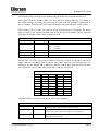
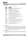
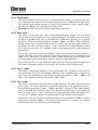
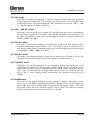
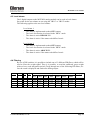
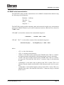
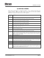
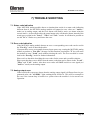
Kokkedal Industripark 4
DK-2980 Kokkedal
Denmark
[email protected]
Tel
+45 49 180 100
Fax
+45 49 180 200
MCE2029 ANALOG MODULE
User manual for system with digital loadcells
Applies for:
Program no.:
MCE2529.STD.120322.0
Document no.:
0322mu2029-2010-0a.DOC
Date:
2012-06-04
Rev.:
0a
MCE2029: User manual
1) CONTENTS
1) CONTENTS ...................................................................................................................................................................2
2) INTRODUCTION ..........................................................................................................................................................3
2.1 Introduction...............................................................................................................................................................3
3) MCE2010 DESCRIPTION.............................................................................................................................................4
4) USER INTERFACE .......................................................................................................................................................6
4.1 Display, lamps and keyboard ....................................................................................................................................6
4.2 Display modes...........................................................................................................................................................7
4.2.1
LoAd mode .................................................................................................................................................7
4.2.2
OutPut mode................................................................................................................................................7
4.2.3
PASS mode .................................................................................................................................................8
4.2.4
ZEro mode...................................................................................................................................................8
4.2.5
CAL.L. mode ..............................................................................................................................................8
4.2.6
CAL. mode..................................................................................................................................................8
4.2.7
CAL.F. mode...............................................................................................................................................9
4.2.8
N.Lc. mode..................................................................................................................................................9
4.2.9
N.Crn. mode ................................................................................................................................................9
4.2.10 Int.PEr. mode ..............................................................................................................................................9
4.2.11 Unit mode....................................................................................................................................................9
4.2.12 dPno mode...................................................................................................................................................9
4.2.13 div mode....................................................................................................................................................10
4.2.14 SP. 1 and SP. 2 mode ................................................................................................................................10
4.2.15 An.SP. mode..............................................................................................................................................10
4.2.16 An.Err. mode.............................................................................................................................................10
4.2.17 An.tyPE. mode ..........................................................................................................................................10
4.2.18 rS485 mode ...............................................................................................................................................10
4.2.19 dAc.tSt. mode............................................................................................................................................11
4.2.20 LC x mode.................................................................................................................................................11
4.2.21 Err.rEg. mode ............................................................................................................................................11
4.3 Level alarms............................................................................................................................................................12
4.4 Filtering...................................................................................................................................................................12
4.5 RS485 serial communication ..................................................................................................................................13
5) STATUS CODES .........................................................................................................................................................14
6) ERROR CODES...........................................................................................................................................................15
7) TROUBLE SHOOTING ..............................................................................................................................................16
7.1 Status code indication .............................................................................................................................................16
7.2 Error code indication...............................................................................................................................................16
7.3 Analog output error .................................................................................................................................................16
8) INSTALLATION OF SYSTEM ..................................................................................................................................17
8.1 Checklist during installation ...................................................................................................................................17
8.2 Calibration procedure..............................................................................................................................................18
9) HARDWARE DESCRIPTION ....................................................................................................................................19
9.1 MCE2029 overview ................................................................................................................................................19
9.2 Connection of power and load cells ........................................................................................................................20
9.3 DIP-switch settings .................................................................................................................................................20
9.4 Light Emitting Diodes.............................................................................................................................................21
9.5 Jumpers ...................................................................................................................................................................21
9.6 JTAG connector ......................................................................................................................................................22
9.7 RS485 connector .....................................................................................................................................................22
9.8 Analog output connector .........................................................................................................................................22
9.9 Digital output and input connector..........................................................................................................................23
9.10 Hardware Selftest..................................................................................................................................................23
9.11 Update times .........................................................................................................................................................23
9.12 Component layout .................................................................................................................................................24
Version: 2012-06-04, rev.: 0a
Page: 2
MCE2029: User manual
2) INTRODUCTION
2.1 Introduction
This document describes the use of a MCE2029 analog module from Eilersen Electric,
when they are equipped with the program listed on the front page.
With the program specified on the front page, the MCE2029 analog module is capable of
transmitting the weight for a system with up to 8 load cells as an analog 4-20 mA signal (or
0-10V depending on factory settings). Each load cell is connected to the MCE2029 analog
module through a load cell interface module.
By use of DIP switches it is possible to include one of 3 different FIR filters, which will be
used to filter the weight signal.
IMPORTANT: Load cell modules and instrumentation must be placed outside the
hazardous zone if the load cells are used in hazardous ATEX (Ex) area. Furthermore,
only ATEX certified load cells and instrumentation can be used in ATEX applications.
Version: 2012-06-04, rev.: 0a
Page: 3
MCE2029: User manual
3) MCE2010 DESCRIPTION
Below the layout of the MCE2010 load cell module is shown. Before using the system the
load cells must be connected to the load cell modules.
Please notice that the load cell and the load cell module MUST be marked
with the same year/serial number. These are printed on the type-plate of the
load cell and on a small sticker placed below the BNC plug on the load cell
module. Load cells and load cell modules MUST NOT be intermixed because
the program in each load cell module is SPECIALLY adapted to one load cell only (and only this load cell). The load cell module MUST be connected to
exactly the load cell it is intended for and vice versa.
Flat cable connector
10 contacts
TXBB
1
ON
SW
1
8
D1
SYNC
ERR
MCE2010
Eilersen Electric
BNC connector
for loadcell
The load cell modules are connected to each other using the supplied cable (10 pole ribbon
cable). The MCE2029 analog module is connected using the same cable.
Version: 2012-06-04, rev.: 0a
Page: 4
MCE2029: User manual
All switches (SW1) in the load cell module must be at the correct position before use.
Please notice that the switches (SW1) are only read once during power-up. If a change in
the switch setting is necessary the power has to be disconnected and then reconnected (after 10 seconds). Then the MCE2010 load cell module recognizes the new switch setting.
The switches SW1.1 to SW1.4 are used to select different modes of operation. The below
table is valid for the normal standard software in the load cell module. Unless expressly
specified, the default settings must normally be used.
MCE2010 SW1.1 to SW1.4
SW1 No
Default setting
Function
1
OFF
2
3
4
ON
ON
OFF
Baud rate
OFF:
115200
ON:
230400
Filter, MSB
Filter, LSB
Not used
Switch SW1.5 to SW1.8 are used for address selection. All load cell modules must have
unique addresses ascending from 0 with no gaps unless expressly specified otherwise. No
addresses may be skipped and no addresses may be used by more than one load cell module. In systems with 1-8 load cells switch SW1.5 must be set to OFF.
MCE2010 SW1.6 to SW1.8
SW1.5
SW1.6
SW 1.7
SW1.8
Address
OFF
OFF
OFF
OFF
OFF
OFF
OFF
OFF
OFF
OFF
OFF
OFF
ON
ON
ON
ON
OFF
OFF
ON
ON
OFF
OFF
ON
ON
OFF
ON
OFF
ON
OFF
ON
OFF
ON
0
1
2
3
4
5
6
7
The three LED’s are used to indicate the following conditions:
MCE2010 LED’S
TXBB
Green
D1
Yellow
SYNC ERR
Red
Version: 2012-06-04, rev.: 0a
Lit whenever the load cell module transmits data. Must be
on/flashing rapidly whenever the system is started.
No synchronization between load cell modules: One or more load
cells not connected to load cell module or poor connection.
No load cell synchronization: No load cell connected to load cell
module or poor connection.
Page: 5
MCE2029: User manual
4) USER INTERFACE
4.1 Display, lamps and keyboard
The MCE2029 analog module is operated using a display, a series of control lamps, 4 DIPswitches and 5 keys.
The control lamps have the following functions:
TXBB
(Green)
Lit when communicating with the connected load cell modules.
D1
(Yellow) Lit when a key is activated.
AN.ERR.
(Red)
Lit when the analog output signal is different from its programmed value.
The 5 keys have the following functions:
”F”
Cyclic change between different display modes etc.
”Up”
Increments desired value etc.
”Down”
Decrements desired value etc.
”Esc”
Regret desired value etc.
”Enter”
Accept of selected display value etc. This key must be pressed
in order to accept any change of parameter
The ”F” key can be used to change between different display modes. In a given mode the
display will alternately show ”XXXXXX” and ”YYYYYY”. Here ”XXXXXX” will be a
text indicating the actual mode, while ”YYYYYY” will indicate the actual value belonging
to this mode.
By holding down the ”F” key and then pressing ”Esc” the LoAd” mode is selected.
If during power-on the display shows ”Par.SEt.” this is because parameters have to be set.
The ”F” key can then be used to proceed to “LoAd” mode and the chapter describing
”Err.rEg.” mode can be used for further information.
If at any time the display shows ”-OL-” (OverLoad) or ”-UL-” (UnderLoad) this is because the actual value to be shown in the display is too large/small.
Version: 2012-06-04, rev.: 0a
Page: 6
MCE2029: User manual
4.2 Display modes
It is possible to select between the following modes:
MODE
”LoAd”
”OutPut”
”PASS”
”ZEro”
”CAL.L.”
”CAL.”
”CAL.F.”
”n.Lc.”
”n.Crn.”
”Int.PEr.”
”Unit”
”dPno”
”div”
”SP. 1”
”SP. 2”
”An.SP.”
”An.Err.”
”An.tyPE.”
”rS485”
”dAc.tSt.”
” LC x ”
”Err.rEg.”
FUNCTION
used during normal operation for display of gross weight.
used for display of the actual analog output signal.
used during selection of password.
used during zero of the weight indication.
used during calibration of the weight indication.
used during calibration of the weight indication.
used to calculate the calibrated weight indication.
used to indicate number of loadcells.
used to indicate number of corners (supporting points).
used to indicate integration period (measurement time).
used to set desired weighing parameters (unit).
used to set desired weighing parameters (decimal point position).
used to set desired weighing parameters (division).
used to control digital output 1.
used to control digital output 2.
used to indicate weight value for full analog output signal.
used to set analog output signal used during status code indication.
used to select signal transferred on the analog output.
used to select signal transferred on the serial RS485 channel.
used to test the analog output signal.
used to show loadcell status/signal for loadcell x (0-7).
used to show various error codes.
4.2.1 LoAd mode
This mode is used during normal operation to show the actual gross weight. The weight indication is indicated in gram, kg or ton depending on the selected weighing parameters
(”Unit” , ”dPno” and ”div”). If the MCE2029 analog module detects a situation that results in a status code indication different from 0, the display will show the status code as “xxxx-“ instead of the weight indication, and it will output its error value (see ”An.Err.”
mode) on its analog output for the duration of this situation.
4.2.2 OutPut mode
This mode is used for indication of the actual analog output signal. The analog output signal is shown in mA/V depending on the hardware configuration of the MCE2029 analog
module.
Version: 2012-06-04, rev.: 0a
Page: 7
MCE2029: User manual
4.2.3 PASS mode
This mode is used to select password. To avoid unintended change of parameters the module is equipped with a password. To change parameters, zero or calibrate the weight indication from the keyboard the user has to set the actual password so that it equals ”1357”.
Hereafter the ”Enter” key is pressed to accept the value.
Remember to clear the password in the same fashion when done.
4.2.4 ZEro mode
This mode is used during zero of the weight indication (gross weight). The zero should
only be done with an empty and clean weighing platform. The display shows the actual
weight as in ”LoAd” mode. The weight indication is indicated in gram, kg or ton depending on the selected weighing parameters (”Unit” , ”dPno” and ”div”). If the MCE2029
analog module detects a situation that results in a status code indication different from 0,
the display will show the status code as “-xxxx-“ instead of the weight indication, and it
will output its error value (see ”An.Err.” mode) on its analog output for the duration of
this situation.
The zeroing is performed by pressing ”Enter”, if the correct password has been selected. A
zeroed and empty system will cause the analog output signal to go to its minimum value
(4mA or 0V). Note that on a MCE2029 analog module running in current configuration,
the analog output signal can go below 4mA for negative weight indications.
The zeroing can also be made using the digital input IN1. Zeroing using the digital input
IN1 can be performed regardless of password value and the selected display mode.
4.2.5 CAL.L. mode
This mode is used during calibration of the weight indication. The display shows the desired calibration load to be used during calibration. The calibration load is indicated in
gram, kg or ton depending on the selected weighing parameters (”Unit” , ”dPno” and
”div”). The calibration itself is performed in ”CAL.” mode.
4.2.6 CAL. mode
This mode is used during calibration of the weight indication. The display shows the actual
gross weight. The weight indication is indicated in gram, kg or ton depending on the selected weighing parameters (”Unit” , ”dPno” and ”div”). If the MCE2029 analog module
detects a situation that results in a status code indication different from 0, the display will
show the status code as “-xxxx-“ instead of the weight indication, and it will output its error value (see ”An.Err.” mode) on its analog output for the duration of this situation.
Calibration of the gross weight to match the calibration load entered in ”CAL.L.” mode is
performed by pressing ”Enter”, if the correct password has been selected. The complete
calibration procedure for calibration is described later.
Version: 2012-06-04, rev.: 0a
Page: 8
MCE2029: User manual
4.2.7 CAL.F. mode
This mode is used during reading/adjustment of the calibration factor. The calibration factor is changed after each performed calibration and should be noted so that it is possible to
re-establish the calibration. The calibration factor can be changed directly if the correct
password is selected. The calibration factor lays in the interval 104858 to 943718 with
524288 as the standard calibration factor (corresponding to no calibration). By changing
the calibration factor within this interval it is possible to change the weight indication with
±80%. The procedure for calibration is described below.
4.2.8 N.Lc. mode
This mode is used during installation to indicate the number of load cells (1-8) connected
to the MCE2029 module. As an example, the ”n.Lc.” parameter should be 1 in a system
consisting of a three legged tank, where only one corner contains a load cell. Note that
changing the ”n.Lc.” parameter will clear the ”SP. 1” , ”SP. 2” , ”An.SP.” and the
”CAL.L.” parameters. If a change is made to this parameter, it may be necessary to turn
the power off and on for the change to take effect.
4.2.9 N.Crn. mode
This mode is used during installation to indicate the number of corners (supporting points)
(1-8). Note that it is the total number of supporting points including corners supported by
load cells. As an example, the ”n.Crn.” parameter should be 3 in a system consisting of a
three legged tank. Note that changing the ”n.Crn.” parameter will clear the ”SP. 1” , ”SP.
2” , ”An.SP.” and the ”CAL.L.” parameters.
4.2.10 Int.PEr. mode
This mode is used during installation to indicate the integration period (40ms, 100ms,
200ms, 400ms, 1000ms, 2000ms or 4000ms). This determines the time over which the load
cell(s) are sampled to determine a new weight reading, and thereby how often the analog
output signal is updated.
4.2.11 Unit mode
This mode is used during installation to select the desired unit used when presenting
weight indications in the display. The unit can be set to gram, kg or ton. Note that changing
the ”Unit” parameter will clear the ”SP. 1” , ”SP. 2” , ”An.SP.” and the ”CAL.L.” parameters.
4.2.12 dPno mode
This mode is used during installation to select the desired decimal point position used
when presenting weight indications in the display. The decimal point position specifies the
number of digits following the decimal point, and it can be selected from a range of predefined values. Note that changing the ”dPno” parameter will clear the ”SP. 1” , ”SP. 2” ,
”An.SP.” and the ”CAL.L.” parameters.
Version: 2012-06-04, rev.: 0a
Page: 9
MCE2029: User manual
4.2.13 div mode
This mode is used during installation to select the desired resolution used when presenting
weight indications in the display. The resolution (or division) can be selected from a range
of predefined values. Note that changing the ”div” parameter will clear the ”SP. 1” , ”SP.
2” , ”An.SP.” and the ”CAL.L.” parameters.
4.2.14 SP. 1 and SP. 2 mode
This mode is used to set the two set points (SP1 and SP2) that are used for controlling the
two level alarms implemented on digital outputs OUT1 and OUT2 as described later. The
set points are indicated in gram, kg or ton depending on the selected weighing parameters
(”Unit” , ”dPno” and ”div”).
4.2.15 An.SP. mode
This mode is used during installation to indicate the weight value that should result in
maximum analog output signal (20mA or 10V). The analog set point that results in maximum analog output signal is indicated in gram, kg or ton depending on the selected weighing parameters (”Unit” , ”dPno” and ”div”).
4.2.16 An.Err. mode
This mode is used during installation to indicate the analog value (0-20mA or 0-10V) that
is transferred on the analog output when status indication is different from 0.
4.2.17 An.tyPE. mode
This mode is used during installation (or error finding) to indicate what signal type is used
to determine the signal on the analog output. ”LoAd” can be selected causing the analog
output signal to follow the gross weight indication in ”LoAd” mode. Alternately ”Lc 0” ”Lc 7” can be selected causing the analog output signal to follow one of the loadcell signals in ”LC x” mode. During normal circumstances the parameter should be set to
”LoAd”.
4.2.18 rS485 mode
This mode is used during installation (or error finding) to indicate what signal is transferred on the serial RS485 communication channel. ”LoAd” can be selected causing the
gross weight indication in ”LoAd” mode to be transferred. Alternately ”Lc 0” - ”Lc 7” can
be selected causing one of the loadcell signals in ”LC x” mode to be transferred. During
normal circumstances the parameter should be set to ”LoAd”.
Version: 2012-06-04, rev.: 0a
Page: 10
MCE2029: User manual
4.2.19 dAc.tSt. mode
This mode can be used to test the analog output signal. Once the ”dAc.tSt.” mode is entered the display will show “OFF” indicating that the analog test mode is disabled. To enable the analog test mode the ”Enter” key must be pressed.
When the analog test mode is enabled, the display will show an analog test value that is
sent out on the analog output. NOTE that this value overrides the normal analog output
signal (based on the actual gross weight) for as long as the analog test mode is enabled.
When the analog test mode is enabled, it is possible to change the analog test value by using the ”Up” or ”Down” key. Thus it is possible to set different values from 0mA (or 0V)
to 20mA (or 10V) in increments of 1mA (or 0.5V).
The analog test mode is disabled by pressing the ”Esc” key when still in ”dAc.tSt.” mode.
The analog test mode is also automatically disabled once the ”dAc.tSt.” mode is left by
pressing the ”F” key. Once the analog test mode is disabled, the analog output signal will
be controlled by the actual gross weight once again.
4.2.20 LC x mode
This mode is used to show the status or signal from load cell x. Thus it is possible to read
the status/signal of all connected load cells. If no error is present on the selected load cell,
the display will show the weight indication measured on that load cell. The weight indication is indicated in gram, kg or ton depending on the selected weighing parameters (”Unit”
, ”dPno” and ”div”). If the MCE2029 analog module detects a situation that results in a
status code indication different from 0 for the selected load cell, the display will show the
status code as “-xxxx-“ instead of the weight indication.
4.2.21 Err.rEg. mode
If the MCE2029 analog module detects an error a corresponding error code can be read in
this mode. If present these errors are normally detected upon power up, causing the
MCE2029 analog module to produce a ”PAr.SEt.” message. In this situation, pressing the
”F” key will cause the module to enter ”LoAd” mode without clearing the error. The error
can then be examined in the “Err.rEg.” mode for further information.
Please refer to the table describing the error codes for the cause and a possible solution.
Please note that these errors differ from the status codes that can be shown in the ”LoAd” ,
”ZEro” and ”CAL.” modes. Also these error codes will NOT result in a error signal (see
”An.Err.” mode) on the analog output.
Version: 2012-06-04, rev.: 0a
Page: 11
MCE2029: User manual
4.3 Level alarms
The 2 digital outputs on the MCE2029 analog module can be used as level alarms.
Set points for the two alarms are set using the ”SP. 1” or ”SP. 2” modes.
The following applies to the two level alarms:
Level alarm 1:
- The alarm is implemented on the OUT1 output.
- The level of activation is selected in the ”SP. 1” mode.
- The alarm is active BELOW SP1.
- The alarm is active if the status code differs from 0.
Level alarm 2:
- The alarm is implemented on the OUT2 output.
- The level of activation is selected in the ”SP. 2” mode.
- The alarm is active ABOVE SP2.
- The alarm is active if the status code differs from 0.
4.4 Filtering
By use of DIP-switches it is possible to include one of 3 different FIR filters, which will be
used to filter the weight signal. Thus it is possible, to send the unfiltered gross weight
achieved over each integration period (Tavg) through one of the following FIR filters, before the result is displayed and send to the analog output:
SW2.4
OFF
ON
OFF
ON
SW2.3
OFF
OFF
ON
ON
No.
0
1
2
3
Taps
9
21
85
Frequency
Damping
Tavg
40ms
Tavg
100ms
Tavg
200ms
Tavg
400ms
Tavg
1000ms
Tavg
2000ms
Tavg
4000ms
-
-
-
-
-
-
-
6.0 Hz
2.4 Hz
1.2 Hz
0.6 Hz
0.24 Hz
0.12 Hz
0.06 Hz
3.0 Hz
1.2 Hz
0.6 Hz
0.3 Hz
0.12 Hz
0.06 Hz
0.03 Hz
0.75 Hz
0.3 Hz
0.15Hz
0.075Hz
0.03 Hz
0.015Hz
0.0075Hz
-80dB
-80dB
-80dB
NOTE: With both switches OFF, no filtering is performed.
Version: 2012-06-04, rev.: 0a
Page: 12
MCE2029: User manual
4.5 RS485 serial communication
The MCE2029 analog module communicates on its RS485 communication channel using
the following serial parameters:
Baudrate:
Data bits:
Parity:
Stop bits:
9600 bps
8
None
1
The MCE2029 analog module transmits status and measured weight every measurement
period on its RS485 channel (9 pole sub-D connector) based on what has been selected in
”rS485” mode.
If ”LoAd” is selected the contents of the transmitted telegram is:
<Status> , <Load> <LF> <CR>
If ”Lc 0” - ”Lc 7” is selected the contents of the transmitted telegram is:
<LcStatus[x]> , <LcSignal[x]> <LF> <CR>
where:
-
-
-
<LF> is a line feed character.
<CR> is a carriage return character.
<Status> is the status code as shown in the ”LoAd” menu. This is a 4 character long hex number and should be 0000 during normal error free operation.
<Load> is the gross weight as shown in the ”LoAd” menu. This is a 6 character long value. Note that this field will be 7 characters long if a decimal point
is used.
<LcStatus[x]> is the status code as shown in the ”LC x” menu. This is a 4
character long hex number and should be 0000 during normal error free operation.
<LcSignal[x]> is the loadcell signal as shown in the ”LC x” menu. This is a 6
character long value. Note that this field will be 7 characters long if a decimal
point is used.
Version: 2012-06-04, rev.: 0a
Page: 13
MCE2029: User manual
5) STATUS CODES
Status codes can be shown as a 4 digit hex number (“-xxxx-“) instead of the actual gross
weight in ”LoAd” , ”ZEro” and ”CAL.” modes. If more than one of the status conditions
listed below is present, the status codes are OR’ed together.
CODE
(Hex)
CAUSE
0001
Invalid/missing ’sample’ ID
Bad connection between MCE2029 analog module and load cell module.
0002
Load cell timeout
Bad connection between load cell and load cell module.
0004
Load cell not synchronized
Bad connection between load cell and load cell module.
0008
Hardware synchronization error
Cable between load cell modules shorted or disconnected.
0010
Power failure
Supply voltage to load cells is to low.
0020
Overflow in weight calculation
Internal error in load cell module.
0040
Invalid/missing ’latch’ ID
Bad connection between MCE2029 analog module and load cell module.
0080
No answer from load cell module
No data is received from load cell module. This can be caused by the removal of a load cell
module, no power to the module or that the connection between load cell module and
MCE2029 analog module is broken.
Reserved for future use
Reserved for future use
Reserved for future use
0100
0200
0400
0800
1000
2000
4000
8000
No load cell modules answer
Bad connection between MCE2029 analog module and load cell module. Not all telegrams
from MCE2029 analog module are received in load cell module.
Reserved for future use
Reserved for future use
Reserved for future use
Wrong number of load cells
The expected number of load cells found during power-on does not match the number indicated by the ”n.Lc.” parameter. If the ”n.Lc.” parameter setting is correct, it must be examined that all load cell module addresses are correct.
Version: 2012-06-04, rev.: 0a
Page: 14
MCE2029: User manual
6) ERROR CODES
Error codes can be shown as a 4 digit hex number (“ xxxx “) in the ”Err.rEg.” mode.
Please note that these error codes are different from the status codes that can be shown in
”LoAd” , ”ZEro” and ”CAL.” modes. If more than one of the error conditions listed below is present, the error codes are OR’ed together.
CODE
(Hex)
0001
0002
0004
0008
0010
0020
CAUSE/SOLUTION
Reserved for future use
Invalid calibration factor
The calibration factor was out of range during power-up, or the scale is not calibrated yet. Perform a calibration, or manually enter a new calibration factor different from the current, to achieve a valid calibration. Power the system off and
back on to verify the problem has been solved.
Invalid zero
The zero was invalid during power-up, or the scale has not been zeroed yet.
Perform a zero to achieve a valid zero. Power the system off and back on to
verify the problem has been solved.
Reserved for future use
Invalid weighing range parameter(s)
One or more weighing range parameters (”Unit” , ”dPno” and ”div”) were
invalid or haven’t been selected yet. Change all weighing range parameters to
a new value different from their current value. Then change all weighing
range parameters to their desired value. Power the system off and back on to
verify the problem has been solved.
Invalid configuration parameter(s)
One or more configuration parameters (“n.Lc.” , “n.Crn.” , “Int.PEr.” , ”SP.
1” , ”SP. 2” and ”An.SP.”) were invalid or haven’t been selected yet. Change
all configuration parameters to a new value different from their current value.
Then change all configuration parameters to their desired value. Power the
system off and back on to verify the problem has been solved.
Version: 2012-06-04, rev.: 0a
Page: 15
MCE2029: User manual
7) TROUBLE SHOOTING
7.1 Status code indication
If the MCE2029 analog module detects a situation that results in a status code indication
different from 0, the MCE2029 analog module will output its error value (see ”An.Err.”
mode) on its analog output, and the level alarms will both be active, no matter what the
current load is. As described earlier the actual status code will then be shown instead of the
actual gross weight in the ”LoAd” , ”ZEro” and ”CAL.” modes. It will then be possible to
use the ”LC x” modes to try and locate the error.
7.2 Error code indication
If the MCE2029 analog module detects an error a corresponding error code can be read in
the ”Err.rEg.” mode as described earlier.
If present these errors are normally detected upon power up, causing the MCE2029 analog
module to produce a ”PAr.SEt.” message. In this situation, pressing the ”F” key will cause
the module to enter ”LoAd” mode without clearing the error. The error can then be examined in the “Err.rEg.” mode for further information.
Please refer to the table describing the error codes for the cause and a possible solution.
Please note that these errors differ from the status codes that can be shown in the ”LoAd” ,
”ZEro” and ”CAL.” modes. Also these error codes will NOT result in a error signal (see
”An.Err.” mode) on the analog output.
7.3 Analog output error
If the build-in DA-converter detects that the analog output signal is different from its programmed value, the ”AN.ERR.” light emitting diode will be lit. This will for example be
the case if the current-loop is broken in a system where the module is in its current configuration.
Version: 2012-06-04, rev.: 0a
Page: 16
MCE2029: User manual
8) INSTALLATION OF SYSTEM
8.1 Checklist during installation
During installation of the system the following should be checked/performed:
1)
The load cells are mounted mechanically and connected to the MCE2029 analog module using their corresponding load cell
interface module. The load cell addresses are set using the DIP-switches on the load cell interface modules, so that they
forth running from address 0 (0-7).
2)
Check that the RS485 channel, the digital I/O and the analog connections of the MCE2029 analog module are made as described in the hardware description.
3)
Select the desired filter using the DIP switches (Sw2.3-Sw2.4). Power is applied.
4)
Verify that the green TXBB LED on the MCE2029 analog module is lit and that the TXBB LED’s on the load cell interface
modules are also lit (can flash slightly). Also verify that other LED’s on the load cell module behave as expected.
5)
Verify that no “PAr.SEt.” message is produced at power-up. Upon power-up the MCE2029 analog module will automatically produce this message if errors are detected, or enter the “LoAd” mode if no errors are detected. Refer to the chapter
describing error codes on how to solve/remove errors.
6)
Verify that the red AN.ERR LED on the MCE2029 analog module is OFF.
7)
Select “PASS” mode (using the “F” key), set the password to 1357 (using the arrow keys) and accept the value (using the
“Enter” key).
8)
Select “n.Lc.” mode and set the number of load cells connected to the MCE2029 module. If a change is made to this parameter, it may be necessary to turn the power off and on. Remember to set the password to 1357 once again, if power is
turned off and on, and further settings have to be made.
9)
Select “n.Crn.” mode and set the number of corners (supporting points).
10)
Select “Int.PEr.” mode and set the desired integration period (40ms, 100ms, 200ms, 400ms, 1000ms, 2000ms or 4000ms).
11)
Verify that the MCE2029 analog module has found the correct number of load cells and that no status codes (load cell errors) are indicated. The “Lc X” modes may be used to locate the origin of any errors present.
12)
Select proper weighing range parameters using the “Unit” (unit), “dPno” (decimal point position) and “div” (division)
modes. The weighing range parameters should match/reflect the actual weighing system and its capacity.
13)
If the two level alarms implemented on digital outputs OUT1 and OUT2 are to be used set their controlling setpoints using
the “SP. 1” and “SP. 2” modes.
14)
Select “An.SP.” mode and set the load corresponding to 20mA (or 10V).
15)
Select “An.Err.” mode and set value (0-20mA or 0-10V) transferred on the analog output when status code indication is
different from 0.
16)
Select “An.tyPE.” mode and check that “LoAd” is selected, so “LoAd” mode determines the analog signal.
17)
Select “rS485” mode and check that “LoAd” is selected, so “LoAd” mode determines the signal on the RS485 channel.
18)
Select “ZEro” mode, and with an empty weighing system zero the system by pressing “Enter”.
19)
Perform a calibration of the system as described below.
20)
Select “OutPut” mode and verify using an instrument that the physical analog output signal behaves as expected depending
on the actual load. If desired the “dAc.tSt.” mode can be used in addition to manually generate different analog test signals.
The system is now installed and a final zero can be made before the password is cleared
(set to 0 and press the “Enter” key) and the module is set to “LoAd” mode.
Version: 2012-06-04, rev.: 0a
Page: 17
MCE2029: User manual
8.2 Calibration procedure
Calibration of the MCE2029 analog module and the connected load cells is made using the
following procedure:
1)
2)
3)
4)
5)
6)
7)
8)
9)
Allow calibration by selecting the correct password (1357) in ”PASS” mode.
Check that the weighing arrangement is empty and clean.
Zero the system using ”ZEro” mode.
Check that the weight indication is zero. Zero again if necessary.
Place the calibration load on the system. The load should be as close to the maximum load as possible. In order to achieve a correct calibration of the system it is
recommended, that the used calibration load is at least 50% of the system capacity.
Select ”CAL.L.” mode and set the calibration load to match the applied load
Select ”CAL.” mode and calibrate the system by pressing the ”Enter” key.
Hereby the calibration factor is changed so that the weight indication matches the
actual load. This is verified in ”LoAd” mode. Note that it is only possible to calibrate within an interval of ±80%. If this is not enough, the mechanical part of the
system should be checked, since this is most likely the cause to the problem.
Select ”CAL.F.” mode and note the achieved calibration factor, so that the calibration can be re-established later.
The system is calibrated and the calibration should be protected by clearing the
password (set to 0). Select ”LoAd” mode and verify that a given load results in a
matching weight indication.
The weight indication can also be calibrated directly by changing the calibration factor in
”CAL.F.” mode. The following relationship between calibrated indication, uncalibrated
indication and the calibration factor applies:
WeightCAL. = [(CALFAC) / 524288] * WeightUNCAL.
Note that the standard calibration factor of 524288 results in no calibration.
Version: 2012-06-04, rev.: 0a
Page: 18
MCE2029: User manual
9) HARDWARE DESCRIPTION
9.1 MCE2029 overview
The following figure is an overview of the MCE2029 analog module:
Version: 2012-06-04, rev.: 0a
Page: 19
MCE2029: User manual
9.2 Connection of power and load cells
The connection of power supply and load cells to the MCE2029 analog module is made as
follows.
The 2 pole connector (J6) located above the display on the MCE2029 analog module is
connected to 24VDC. The 2 pole connector (J6) on the MCE2029 analog module has these
connections:
PIN NO. PIN DESIGNATION
1
2
+
-
CONNECTION
+24VDC (Vin)
0 VDC (GNDin)
IMPORTANT: The used power supply must be stable and free of transients. It may therefore be necessary to use a separate power supply dedicated to the weighing system, and not
connected to any other equipment.
The 10 pole connector (J2) located above the display on the MCE2029 analog module is
connected to the 10 pole connectors on the load cell interface modules (MCE2010) using
the supplied ribbon cable with mounted connectors. Through this bus cable the MCE2029
analog module supplies the load cell modules with +24VDC, and data can be transferred
from the load cell modules to the MCE2029 analog module. The 10 pole connector (J2) on
the MCE2029 analog module has these connections:
MCE2029 J2 CONNECTOR
FUNCTION
J2.1 – J2.2
J2.3 – J2.4
J2.5 – J2.6
J2.7 – J2.8
J2.9 – J2.10
RS485-B (DATA- )
RS485-A (DATA+)
0 VDC (GND)
+24VDC
I/O line
9.3 DIP-switch settings
The MCE2029 analog module is equipped with a 4 pole DIP-switch block (SW2). The
switches are only read during power-on, and have the following function..
SWITCH
Sw2.1-Sw2.2
Sw2.3-Sw2.4
Version: 2012-06-04, rev.: 0a
FUNCTION
Reserved for future use.
Filtering
Used to select the desired filter as described in an earlier chapter.
Page: 20
MCE2029: User manual
9.4 Light Emitting Diodes
The MCE2029 analog module is equipped with 3 light emitting diodes (LED). These
LED’s have the following function:
LED
TXBB
(Green)
D1
(Yellow)
AN.ERR.
(Red)
FUNCTION
Communication with load cells
MCE2029 analog module is communicating with load cells.
Key is pressed
A key on the keyboard is pressed.
Analog Error
The current on the analog output differs from its programmed value.
This may be the case if the current-loop is broken.
9.5 Jumpers
The MCE2029 analog module is equipped with 8 jumpers. These jumpers are only read at
power-on, and they have the following functions:
JUMPER
JU1
JU6
JU7
JU8
JU12
FUNCTION
Analog output type (mA or Volt)
Jumper OFF : mA output (normal default factory)
Jumper ON : Voltage output
Reserved for future use
(normal default factory setting is OFF)
Reserved for future use
(normal default factory setting is OFF/UNSOLDERED)
Reserved for future use
(normal default factory setting is OFF/UNSOLDERED)
REFIN – REFOUT short
(setting must always be OFF)
J4
Analog output type (mA or Volt)
Jumper on pin 1-2 : mA output (normal default factory)
Jumper on pin 2-3 : Voltage output
J8
DAC Range Select 1
Jumper on pin 1-2 : not used
Jumper on pin 2-3 : mA or Voltage output (normal default factory)
J9
DAC Range Select 2
Jumper on pin 1-2 : mA output (normal default factory)
Jumper on pin 2-3 : Voltage output
IMPORTANT: The placement of these should not be changed without consulting Eilersen Electric A/S.
Changing jumper settings subsequently requires a fine adjustment of the hardware calibration of the analog
output using the potentiometers P1 (SPAN/GAIN) and P2 (OFFSET/ZERO).
Version: 2012-06-04, rev.: 0a
Page: 21
MCE2029: User manual
9.6 JTAG connector
The MCE2029 analog module is equipped with an internal JTAG connector. The connector
(J5) is used exclusively by Eilersen Electric A/S for download of software to the Cygnal
processor.
9.7 RS485 connector
The MCE2029 analog module is equipped with a 9 pole female sub-D connector for RS485
connection. The connector (J12) is used exclusively by Eilersen Electric A/S for connection to
a PC for configuration/monitoring of the MCE2029 analog module. The connector (J12) has
the following pin out:
9 pole subD (J12) FUNCTION
J12.5
J12.6
J12.9
RS485-GND
RS485-A (+)
RS485-B (-)
9.8 Analog output connector
The 2 pole connector (J1) located below the display on the MCE2029 analog module is
used for connection of the analog output signal. Connection of the analog output signal is
done as follows:
PIN NO. PIN DESIGNATION FUNCTION
1
2
AN. OUT
AN. RET
Analog output
Analog return
NOTE:
The analog output is an active output, and should NOT be connected to an active input.
Version: 2012-06-04, rev.: 0a
Page: 22
MCE2029: User manual
9.9 Digital output and input connector
The 7 pole connector located below the display on the MCE2029 analog module is used
for connection of the digital outputs and digital inputs. Connection of the digital outputs
and digital inputs is done as follows:
PIN NO. PIN DESIGNATION FUNCTION
1
OUT1
OUT1 - Digital Output 1
Level alarm controlled by SP1. Output is active below SP1.
2
COM
Common
Voltage connected to this pin (normally 24VDC) is sent to
outputs when they are active.
3
OUT2
OUT2 - Digital Output 2
Level alarm controlled by SP2. Output is active above SP2.
4
IN1
Digital Input 1 (IN1) – ZERO
Zeroing of gross weight. Must be active for at least 1 second.
Closing switch to 24VDCout.
5
6
GND
IN2
GND
Digital Input 2 (IN2)
Reserved for future use – NOT connected
7
24V OUT
24VDCout
Used for activating digital inputs.
IMPORTANT: Connection of the digital I/O signals to external equipment must be made
using solid-state-relays (SSR).
9.10 Hardware Selftest
During power-on the MCE2029 analog module will perform a hardware selftest. The test
will cause all the displays to turn on while the light emitting diodes D1 will turn on and off
shortly.
9.11 Update times
All load cells are sampled/averaged over the time period selected in “Int.PEr.” mode (40ms,
100ms, 200ms, 400ms, 1000ms, 2000ms or 4000ms). The hereby found load cell signals are
used to generate the weight reading and the 4-20 mA (or 0-10V) signal until new signals are
achieved when the next sample/average period expires.
Version: 2012-06-04, rev.: 0a
Page: 23
MCE2029: User manual
9.12 Component layout
The following figure is an overview of the component layout on the MCE2029 analog
module:
Version: 2012-06-04, rev.: 0a
Page: 24