1
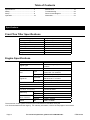
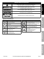
Owner’s Manual & Safety Instructions
Save This Manual Keep this manual for the safety warnings and precautions, assembly,
operating, inspection, maintenance and cleaning procedures. Write the product’s serial number in the
back of the manual near the assembly diagram (or month and year of purchase if product has no number).
Keep this manual and the receipt in a safe and dry place for future reference.
REV 15l
Using an engine indoors
CAN KILL YOU IN MINUTES.
Engine exhaust contains carbon monoxide.
This is a poison you cannot see or smell.
NEVER use inside
a home or garage,
EVEN IF doors and
windows are open.
Only use OUTSIDE
and far away from
windows, doors,
and vents.
Visit our website at: http://www.harborfreight.com
Email our technical support at: [email protected]
Email our engine support at: [email protected]
When unpacking, make sure that the product is intact
and undamaged. If any parts are missing or broken,
please call 1-888-866-5797 as soon as possible.
Copyright© 2015 by Harbor Freight Tools®. All rights reserved.
No portion of this manual or any artwork contained herein may be reproduced in
any shape or form without the express written consent of Harbor Freight Tools.
Diagrams within this manual may not be drawn proportionally. Due to continuing
improvements, actual product may differ slightly from the product described herein.
Tools required for assembly and service may not be included.
Read this material before using this product.
Failure to do so can result in serious injury.
SAVE THIS MANUAL.
Table of Contents
Specifications.............................................. 2
Safety��������������������������������������������������������� 3
Setup........................................................... 8
Operationr��������������������������������������������������� 10
Maintenances���������������������������������������������� 16
Troubleshooting.......................................... 22
Parts List and Diagram............................... 24
Warranties.................................................. 27
Specifications
Front Tine Tiller Specifications
Maximum Tilling Depth
Maximum Tilling Width
Drive Type
Drive Actuation
Depth Adjustment Steps
Overall Dimensions
Wheels
Weight
6.5" (165 mm)
26" (660 mm)
Belt and Chain
Clutch Drive (Handle Lever Operated)
6
51" L x 25" W x 42-1/2" H
8" Diameter x 1-3/4" W
118 Pounds
Engine Specifications
Displacement
Engine Type
Cooling System
Type
Fuel
Capacity
Engine Oil
Type SAE
Capacity
Sound Level at 1 meter
Bore x Stroke
Compression Ratio
Rotation viewed from PTO
(power takeoff - the output shaft)
Spark Plug
Valve Clearance
Speed
Type
Gap
Intake
Exhaust
Idle
208cc
Horizontal Single Cylinder
4-stroke
Forced air cooled
87+ octane unleaded gasoline
treated with fuel stabilizer
0.66 Gallon (2.5 Liter)
10W-30 above 32° F
5W-30 at 32° F or below
20 ounces (0.6 Liter)
95 dB
70 mm x 54 mm
8.8:1
Counterclockwise
Torch® F6TC
0.0275" – 0.0314"
0.0059" – 0.0078"
0.0059"– 0.0078"
1560 ± 50 RPM
The emissions control system for this Engine is warranted for standards set by the
U.S. Environmental Protection Agency. For warranty information, refer to the last pages of this manual.
Page 2
For technical questions, please call 1-888-866-5797.
ITEM 62548
WARNING SYMBOLS AND DEFINITIONS
This is the safety alert symbol. It is used to alert you to potential
personal injury hazards. Obey all safety messages that
follow this symbol to avoid possible injury or death.
Safety
Indicates a hazardous situation which, if not avoided,
will result in death or serious injury.
Indicates a hazardous situation which, if not avoided,
could result in death or serious injury.
Indicates a hazardous situation which, if not avoided,
could result in minor or moderate injury.
Addresses practices not related to personal injury.
RPM
HP
Property or Statement
Revolutions Per Minute
Horsepower
WARNING marking concerning
Risk of Eye Injury. Wear ANSI-approved
safety goggles with side shields.
Read the manual before
set-up and/or use.
Property or Statement
WARNING marking concerning
Risk of Respiratory Injury.
Operate engine OUTSIDE and far away
from windows, doors, and vents.
WARNING marking concerning
Risk of Fire while handling fuel.
Do not smoke while handling fuel.
WARNING marking concerning
Risk of Fire.
Do not refuel while operating.
Keep flammable objects
away from engine.
Maintenance
WARNING marking concerning
Risk of Hearing Loss.
Wear hearing protection.
Symbol
Operation
Symbol
Setup
Symbol Definitions
ITEM 62548
For technical questions, please call 1-888-866-5797.
Page 3
IMPORTANT
Safe Operation Practices for Walk-Behind
Powered Rotary Tillers and Hand Supported Cultivators
Safety
Training
1. Read the operating and service instruction manual
carefully. Be thoroughly familiar with the controls
and the proper use of the equipment. Know how to
stop the unit and disengage the controls quickly.
2. Never allow children to operate the
equipment. Never allow adults to operate
the equipment without proper instruction.
3. Keep the area of operation clear of all persons,
particularly small children, and pets.
4. Keep in mind that the operator or user is
responsible for accidents or hazards occurring to
other people, their property, and themselves.
Preparation
Setup
1. Thoroughly inspect the area where the equipment
is to be used and remove all foreign objects.
5. Never attempt to make any adjustments
while the engine is running.
2. Disengage all clutches and shift into
neutral before starting the engine.
6. Have multiple ABC class fire extinguishers nearby.
3. Do not operate the equipment without wearing
adequate outer garments. Wear protective footwear
that will improve footing on slippery surfaces.
4. Warning: Fuel is highly flammable.
Take the following precautions:
(a)Store fuel in containers specifically
designed for this purpose.
(b)Refuel outdoors only and do not
smoke while refueling.
Operation
(c)Add fuel before starting the engine. Never
remove the cap of the fuel tank or add fuel while
the engine is running or when the engine is hot.
(d)If fuel is spilled, do not attempt to start the
engine but move the machine away from the
area of spillage and avoid creating any source
of ignition until fuel vapors have dissipated.
(e)Replace all fuel tank and container caps securely.
7. Operation of this equipment may create sparks that
can start fires around dry vegetation.
A spark arrestor may be required. The operator
should contact local fire agencies for laws or
regulations relating to fire prevention requirements.
8. Set up and use only on a flat, level,
well‑ventilated surface.
9. Wear ANSI-approved safety goggles, heavy-duty
work gloves, and dust mask/respirator during set up.
10. Use only lubricants and fuel recommended
in the Specifications chart of this manual.
11. NEVER till above or near any electrical
cables, gas pipes, or any other utility lines.
Contact your local utility company
before using the Front Tine Tiller.
12. Thoroughly inspect the area where the
Front Tine Tiller is to be used. Beware of possible
buried obstacles such as cable, conduit, irrigation
lines, and landscape fabric. Remove all large
sticks, stones, wires, or other foreign objects.
Maintenance
Page 4
For technical questions, please call 1-888-866-5797.
ITEM 62548
Operation
2. Exercise extreme caution when operating on or
crossing gravel drives, walks, or roads. Stay alert for
hidden hazards or traffic. Do not carry passengers.
3. After striking a foreign object, stop the
engine, remove the wire from the spark
plug, thoroughly inspect the machine for
any damage, and repair the damage before
restarting and operating the machine.
22. Do not operate the tiller while under
the influence of alcohol or drugs.
23.
CARBON MONOXIDE HAZARD
Using an engine indoors
CAN KILL YOU IN MINUTES.
Engine exhaust contains
carbon monoxide. This is a poison
you cannot see or smell.
Safety
1. Do not put hands or feet near or under rotating parts.
4. Exercise caution to avoid slipping or falling.
5. If the unit should start to vibrate abnormally, stop
the engine and check immediately for the cause.
Vibration is generally a warning sign of trouble.
NEVER use inside a home or garage,
EVEN IF doors and windows are open.
9. Do not operate the engine in a confined space
where dangerous carbon monoxide gas can collect.
10. Never operate the machine without proper guards,
plates, or other safety protective devices in place.
11. Keep children and pets away.
12. Do not overload the machine capacity by
attempting to till too deep at too fast a rate.
13. Never operate the machine at high transport
speeds on hard or slippery surfaces.
14. Never allow bystanders near the unit.
15. Use only attachments and accessories approved
by the manufacturer of the machine (such as
wheel weights, counterweights, and the like).
16. Never operate the tiller without good visibility or light.
17. Be careful when tilling in hard ground.
The tines may catch in the ground and propel
the tiller forward. If this occurs, let go of the
handlebars and do not restrain the machine.
18. Use extreme caution when reversing or
pulling the machine towards you.
19. Do not change the engine governor
settings or overspeed the engine.
20. Start the engine carefully according to instructions
and with feet well away from the tines
21. Never pick up or carry a machine
while the engine is running.
ITEM 62548
Only use OUTSIDE and far away from windows,
doors, and vents.
24. DO NOT engage the Forward and
Reverse Clutch Levers at the same time.
This will result in unpredictable Tiller behavior
and possible equipment damage.
25. Do not use the Front Tine Tiller on steep
inclines. Use only on level ground surfaces.
26. Keep a safe distance from the edges
and banks of ditches. Avoid any actions
that may cause the Tiller to tip over.
Operation
8. Before cleaning, repairing, or inspecting, shut
off the engine and make certain all moving
parts have stopped. Disconnect the spark
plug wire, and keep the wire away from
the plug to prevent accidental starting.
Setup
7. Take all possible precautions when leaving the
machine unattended. Disengage the power
take-off, lower the attachment, shift into neutral,
stop the engine, and remove the key.
27. Do not touch engine during use.
Let engine cool down after use.
28. Industrial applications must follow
OSHA requirements.
29. The equipment can produce high noise levels.
Prolonged exposure to noise levels
above 85 dBA is hazardous to hearing.
Wear ear protection when operating the equipment.
30. Wear ANSI-approved safety glasses,
hearing protection, heavy‑duty work gloves
and steel-toed boots during use.
31. People with pacemakers should consult their
physician(s) before use. Electromagnetic fields in
close proximity to a heart pacemaker could cause
pacemaker interference or pacemaker failure.
Caution is necessary when near the
engine’s magneto or recoil starter.
32. Do not operate in explosive atmospheres,
such as in the presence of flammable
liquids, gases, or dust. Gasoline-powered
engines may ignite the dust or fumes.
For technical questions, please call 1-888-866-5797.
Page 5
Maintenance
6. Stop the engine when leaving the operating
position, before unclogging the tines, and when
making any repairs, adjustments, and inspections.
33. Use this equipment with both hands only.
Using equipment with only one hand
can easily result in loss of control.
Safety
34. Dress properly. Do not wear loose clothing or
jewelry. Keep hair, clothing and gloves away
from moving parts. Loose clothes, jewelry or
long hair can be caught in moving parts.
35. Parts, especially exhaust system components,
get very hot during use. Stay clear of hot parts.
36. Do not cover the equipment during operation.
37. Keep the equipment, engine, and
surrounding area clean at all times.
38. Do not operate the equipment with known
leaks in the engine’s fuel system.
39. WARNING: This product contains or, when
used, produces a chemical known to the State
of California to cause cancer and birth defects
or other reproductive harm. (California Health
& Safety Code § 25249.5, et seq.)
40. WARNING: This product contains di (2-ethylhexyl)
phthalate (DEHP), a chemical known to the State
of California to cause cancer and birth defects
or other reproductive harm. (California Health
& Safety Code § 25249.5, et seq.)
41. When spills of fuel or oil occur, they must be
cleaned up immediately. Dispose of fluids and
cleaning materials as per any local, state, or
federal codes and regulations. Store oil rags in
a bottom-ventilated, covered, metal container.
42. Before use, check for misalignment or binding of
moving parts, breakage of parts, and any other
condition that may affect the equipment’s operation.
If damaged, have the equipment serviced
before using. Many accidents are caused
by poorly maintained equipment.
43. Do not modify the Tiller and do not use the Tiller
for a purpose for which it is not intended.
Setup
Operation
Maintenance
Page 6
For technical questions, please call 1-888-866-5797.
ITEM 62548
Maintenance and Storage
3. Never store the machine with fuel in the fuel
tank inside a building where ignition sources are
present, such as hot water and space heaters,
clothes dryers, and the like. Allow the engine
to cool before storing in any enclosure.
4. Always refer to the operator’s manual
for important details if the tiller is to be
stored for an extended period.
5. If the fuel tank has to be drained, do this outdoors.
6. Follow manufacturer’s recommendations
for safe loading, unloading, transport,
and storage of machine.
7. Before service, maintenance, or cleaning:
a. Turn the Engine Switch to its “OFF” position.
b. Allow the Engine to completely cool.
c. Then, remove the Spark Plug Cap
from the Spark Plug.
9. Do not store fuel or other flammable
materials near the engine.
Safety
2. Check shear bolts, engine mounting bolts, and other
bolts at frequent intervals for proper tightness to be
sure the equipment is in safe working condition.
8. Do not alter or adjust any part of the
equipment or its engine that is sealed
by the manufacturer or distributor.
10. Wear ANSI-approved safety goggles,
heavy‑duty work gloves, and
dust mask/respirator during service.
11. Maintain labels and nameplates on the equipment.
These carry important information.
If unreadable or missing, contact
Harbor Freight Tools for a replacement.
12. Have the equipment serviced by a qualified repair
person using only identical replacement parts.
This will ensure that the safety of the equipment
is maintained. Do not attempt any service or
maintenance procedures not explained in this
manual or any procedures that you are uncertain
about your ability to perform safely or correctly.
13. Store equipment out of the reach of children.
14. Follow scheduled engine and
equipment maintenance.
Setup
1. Keep machine, attachments, and
accessories in safe working condition.
WARNING! Read all instructions.
Failure to follow all instructions listed below may result in fire, serious injury and/or DEATH.
The warnings and precautions discussed in this manual cannot cover all possible conditions and
situations that may occur. It must be understood by the operator that common sense and caution
are factors which cannot be built into this product, but must be supplied by the operator.
Maintenance
Operation
SAVE THESE INSTRUCTIONS.
ITEM 62548
For technical questions, please call 1-888-866-5797.
Page 7
Set Up
Read the ENTIRE IMPORTANT SAFETY INFORMATION section at the beginning of this manual
including all text under subheadings therein before set up or use of this product.
Safety
TO PREVENT SERIOUS INJURY: Operate only with proper spark arrestor installed.
Operation of this equipment may create sparks that can start fires around dry vegetation.
A spark arrestor may be required. The operator should contact local fire agencies for laws or
regulations relating to fire prevention requirements.
TO PREVENT SERIOUS INJURY FROM ACCIDENTAL STARTING: Turn the Power Switch
of the equipment to its “OFF” position, wait for the engine to cool, and unplug the spark
plug wire(s) before assembling or making any adjustments to the equipment.
At high altitudes, the engine’s carburetor, governor (if so equipped), and any other parts that control
the fuel-air ratio will need to be adjusted by a qualified mechanic to allow efficient high-altitude
use and to prevent damage to the engine and any other devices used with this product.
Note: For additional information regarding the parts listed in the following pages,
refer to the Assembly Diagram near the end of this manual.
Setup
Assembly
Attach the Handlebar Assembly to the Handlebar Frame (49) using four Hex Head Flange
Bolts (72), Flat Washers (66), Spring Washers (67), and Nuts (62). Refer to Figure A.
Handlebar Assembly
Operation
Flat Washer,
Spring Washer
& Nut
Flange
Bolt
Maintenance
Handlebar
Frame
Figure A
Page 8
For technical questions, please call 1-888-866-5797.
ITEM 62548
Engine
Switch
Forward Clutch
Lever
Reverse
Clutch Lever
Muffler
Fuel Cap
Setup
Throttle
Control
Safety
Components and Controls
Oil Cap/
Dipstick
Air
Filter
Oil Drain
Plug
Fuel
Valve
Maintenance
Choke
Starter
Handle
Tines
ITEM 62548
For technical questions, please call 1-888-866-5797.
Operation
Drag
Bar
Page 9
Operation
Read the ENTIRE IMPORTANT SAFETY INFORMATION section at the beginning of this manual
including all text under subheadings therein before set up or use of this product.
Safety
Engine and Equipment Pre-Start Checks
Inspect engine and equipment looking for damaged, loose, and missing parts before set up and starting.
If any problems are found, do not use equipment until fixed properly.
Checking and Filling Engine Oil
NOTICE: Your Warranty is VOID if the engine’s
crankcase is not properly filled with oil before
each use. Before each use, check the oil level.
Engine will not start with low or no engine oil.
1. Make sure the engine is stopped and is level.
2. Close the Fuel Valve.
Setup
3. Clean the top of the Dipstick and the area around it.
Remove the Dipstick by turning it counterclockwise,
and wipe it off with a clean, lint free rag.
4. Reinsert the Dipstick without threading it in and
remove it to check the oil level. The oil level
should be up to the full level as shown at right.
Full level
5. If the oil level is at or below the low mark add the
appropriate type of oil until the oil level is at the
proper level. SAE 10W‑30 oil is recommended for
general use. (The SAE Viscosity Grade chart on
page 18 in the Maintenance section shows other
viscosities to use in different average temperatures.)
6. Thread the dipstick back in clockwise.
NOTICE: Do not run the engine with too little oil.
The engine will shut off if too little engine oil is used.
Operation
Maintenance
Page 10
For technical questions, please call 1-888-866-5797.
ITEM 62548
Checking and Filling Fuel
1. Clean the Fuel Cap and the area around it.
2. Unscrew and remove the Fuel Cap.
3. Remove the Strainer and remove any dirt
and debris. Then replace the Strainer.
4. If needed, fill the Fuel Tank to about 1 inch under
the fill neck of the Fuel Tank with 87 octane or
higher unleaded gasoline that has been treated
with a fuel stabilizer additive. Follow fuel stabilizer
manufacturer’s recommendations for use.
5. Then replace the Fuel Cap.
6. Wipe up any spilled fuel and allow excess
to evaporate before starting engine.
To prevent FIRE, do not start the engine
while the smell of fuel hangs in the air.
Maintenance
Operation
Setup
Note: Do not use gasoline containing more than
10% ethanol (E10). Do not use E85 ethanol. Add fuel
stabilizer to the gasoline or the Warranty is VOID.
Note: Do not use gasoline that has been stored in a
metal fuel container or a dirty fuel container. It can
cause particles to enter the carburetor, affecting
engine performance and/or causing damage.
Safety
WARNING! TO PREVENT SERIOUS
INJURY FROM FIRE:
Fill the fuel tank in a well-ventilated area
away from ignition sources. If the engine
is hot from use, shut the engine off and
wait for it to cool before adding fuel. Do not smoke.
ITEM 62548
For technical questions, please call 1-888-866-5797.
Page 11
Starting the Engine
Before Starting the Engine
a. Inspect the equipment and engine.
Safety
b. Fill the engine with the proper amount and type of both oil and
unleaded gasoline treated with fuel stabilizer.
c. Make sure that the Forward and Reverse Clutch Levers are disengaged.
1. To start a cold engine, move the Choke to the
START position.
To restart a warm engine, leave the
Choke in the RUN position.
1
Setup
Operation
2. Open the Fuel Valve.
2
3. Rotate the Throttle Control clockwise to
halfway between the low and high position.
3
Maintenance
4. Turn the Engine Switch on.
4
Note: If engine does not start, check engine oil. Engine
will not start with low or no engine oil.
Page 12
For technical questions, please call 1-888-866-5797.
ON
ITEM 62548
Note: Do not let the Starter Handle snap back against
the Engine. Hold it as it recoils so it doesn't hit the Engine.
5
Safety
5. Grip the Starter Handle of the Engine loosely and pull
it slowly several times to allow the gasoline to flow into
the Engine’s carburetor. Then pull the Starter Handle
gently until resistance is felt. Allow Cable to retract fully
and then pull it quickly. Repeat until the Engine starts.
6. Allow the Engine to run for several seconds.
Then, if the Choke lever is in the START position,
move the Choke lever very slowly to its RUN position.
Note: Moving the Choke lever too
fast could stall the engine.
6
IMPORTANT: Allow the Engine to run at no load for five
minutes after each start‑up so that the Engine can stabilize.
7. Adjust the Throttle Control Lever as needed.
Setup
Break-in Period:
a. Breaking-in the engine will help to ensure proper equipment and engine operation.
b. The operational break-in period will last about 3 hours of use. During this period:
• Do not apply a heavy load to the equipment.
• Do not operate the engine at its maximum speed.
c. The maintenance break-in period will last about 20 hours of use.
• Change the engine oil after this period.
Maintenance
Operation
Under normal operating conditions subsequent maintenance follows
the schedule explained in the Maintenance section.
ITEM 62548
For technical questions, please call 1-888-866-5797.
Page 13
Tiller Operation
Safety
BEWARE of possible buried obstacles such as cable, conduit, irrigation lines, and landscape fabric.
DO NOT till above or near any electrical cables, gas pipes, or any other utility lines.
Contact your local utility company before using the Front Tine Tiller.
1. Before starting the Engine, set the desired tilling
depth (to a maximum 6.5" deep) by adjusting
the Drag Bar (91) and Wheel Assembly:
a. To adjust the Drag Bar remove the R-Clip (35)
and Clevis Pin (78). Lower the Drag Bar to
increase tilling depth or raise Bar to decrease
depth. Replace the Clevis Pin and R-Clip.
Refer to Figure B.
Setup
b. Set the Drag Bar below the level of the
Wheel Assembly. If necessary, remove the
R-Clip (35) and Clevis Pin (77) from the
Wheel Assembly and adjust as needed.
Replace the Clevis Pin and R-Clip.
4. Grip the Handles firmly with both hands.
5. To move the Tiller in a forward direction, make
sure the Reverse Clutch Lever (90) is not
engaged and squeeze down on the Forward Clutch
Lever (89) to rotate the Tines and move forward.
Release the Forward Clutch Lever to stop Tine
rotation and forward movement. Refer to Figure C.
6. To move the Tiller in a reverse direction, make sure
the Forward Clutch Lever is not engaged and pull
up on the Reverse Clutch Lever to rotate the Tines
and move in reverse. Release the Reverse Clutch
Lever to stop Tine rotation and backward movement.
Note: Optimum tilling depth (generally 4"– 6") will vary
with soil conditions. If Tiller shakes or is difficult to
control, the Drag Bar and Wheel Assembly are not
correctly set for the conditions. Adjustment through trial
and error is required to achieve the correct setting.
2. WARNING! Before first use, practice operating the
Tiller controls with Tines raised off of the ground.
Know how to keep control at all times, how to stop
the Tines from turning, and how to stop the Engine.
For actual field use, operate with Throttle Control
in slow position until familiar with Tiller handling.
Operation
Clevis Pin (77)
Drag Bar (91)
Clevis Pin
(78)
R-Clip
(35)
Engaged
Disengaged
Forward
Clutch
Lever
Disengaged
Engaged
Reverse
Clutch
Lever
Figure C
7. The following soil conditions can affect tilling results:
a. On soil that is too hard and/or dried out for
the Tines to penetrate, the Tiller will shake
excessively and jump across the soil surface.
Moisten dry, hardened soil prior to tilling and use
a shallow depth setting and slow Engine speed.
b. Exceedingly wet soil will form clumps
during tilling and clog the Tines. Allow wet
soil to partially dry before tilling and use a
slow Engine speed to improve results.
Maintenance
R-Clip
(35)
Wheel
Assembly
Figure B
3. Start the Engine following instructions
in Manual Start on page 12.
Page 14
CAUTION! DO NOT engage the Forward and
Reverse Clutch Levers at the same time. This will
result in unpredictable Tiller behavior and possible
equipment damage.
NOTICE: Should the Tines jam or the Tiller strike a
foreign object during use, immediately release the
Clutch Lever and turn off the Engine. Wait until the
machine completely stops. Disconnect the Spark Plug
cap, remove foreign objects and inspect the Tiller.
If any damage is found have the problem corrected
before further use.
For technical questions, please call 1-888-866-5797.
ITEM 62548
Narrow Width Tilling
c. Make sure the outer Tine Blades
are removed from both Tine Blade
Assemblies before operating Tiller.
a. Make sure the Engine Switch is in the “OFF”
position and disconnect the Spark Plug cap.
b. Loosen and remove four sets of Bolts (59), Spring
Washers (60), and Nuts (61) securing the outer
Tine Blades in place on the Tine Shaft of each
Tine Blade Assembly. Remove the Blades and
set aside with the hardware. Refer to Figure D.
d. To return to normal width tilling replace the
outer Tine Blades onto both Tine Shafts.
When reattaching the Tine Blades make sure
the Blades and hardware are replaced in
the same orientation as when removed.
Safety
The Tiller may be set up for narrow tilling by removing
the outer Tine Blades from each of the two Tine
Blade Assemblies using the following procedure:
Note: When installed properly the cutting
edges of the Tine Blades will face forward.
Setup
Note: Examine Tine Blade positioning and
hardware alignment before removal to
make correct reattachment easier.
Tine
Shaft
Tine
Shaft
Bolt
Nut
Tine Blade
Tine Blade
Tine Blade Assembly with outer
Tine Blades removed from Tine Shaft.
Spring Washer
Figure D
Operation
Stopping the Engine and Tiller
1. To stop the Engine in an emergency,
turn the Engine Switch off.
2. Under normal conditions, use the following procedure:
a. Release the Clutch Lever.
b. Rotate the Throttle Control
counterclockwise to the low position.
c. Turn the Engine Switch off.
Maintenance
d. Close the Fuel Valve.
e. Clean external parts with clean cloth, remove
debris from Tine Blades and Shaft, then
cover the equipment and store in a dry, level,
well‑ventilated area out of reach of children.
NOTICE
See Long-Term Storage on page 21
for complete storage instructions.
ITEM 62548
For technical questions, please call 1-888-866-5797.
Page 15
Maintenance
Safety
WARNING
TO PREVENT SERIOUS INJURY FROM ACCIDENTAL STARTING:
Turn the Power Switch of the equipment to its “OFF” position, wait for the engine to cool, and disconnect
the spark plug cap before performing any inspection, maintenance, or cleaning procedures.
TO PREVENT SERIOUS INJURY FROM EQUIPMENT FAILURE:
Do not use damaged equipment. If abnormal noise, vibration, or excess
smoking occurs, have the problem corrected before further use.
Follow all service instructions in this manual. The engine may fail critically if not serviced properly.
Many maintenance procedures, including any not detailed in this manual, will need to be performed
by a qualified technician for safety. If you have any doubts about your ability to safely service the
equipment or engine, have a qualified technician service the equipment instead.
Setup
Operation
Maintenance
Page 16
For technical questions, please call 1-888-866-5797.
ITEM 62548
Cleaning, Maintenance, and Lubrication Schedule
Note: The following procedures are in addition to the regular checks and maintenance
explained as part of the regular operation of the engine and equipment.
Before
Each
Use
Procedure
After
Each
Use
Monthly or Every 3 mo. Every 6 mo. Yearly or
every 20
or 50 hr.
or 100 hr. every 300
hr. of use
of use
of use
hr. of use
Every
2 Years
Safety
Note: This maintenance schedule is intended solely as a general guide. If performance decreases or if
equipment operates unusually, check systems immediately. The maintenance needs of each piece of equipment
will differ depending on factors such as duty cycle, temperature, air quality, fuel quality, and other factors.
Brush off outside of engine
Check engine oil level
Check for loose hardware
Clean debris from Tine
Blades and Shaft
Change engine oil
Check air cleaner
Check sediment cup
Check and clean spark plug
1. Check/adjust idle speed
2. Check/adjust valve clearance
3. Clean fuel tank, strainer
and carburetor
**
4. Clean carbon build-up from
combustion chamber
Replace fuel line if necessary
**
Setup
*
Clean air filter
**
Maintenance
Operation
*Service more frequently when used in dusty areas.
**These items should be serviced by a qualified technician.
ITEM 62548
For technical questions, please call 1-888-866-5797.
Page 17
Safety
Checking and Filling Fuel
Engine Oil Change
WARNING! TO PREVENT SERIOUS
INJURY FROM FIRE:
Fill the fuel tank in a well-ventilated area
away from ignition sources. If the engine is
hot from use, shut the engine off and wait
for it to cool before adding fuel. Do not smoke.
CAUTION! Oil is very hot during operation and can
cause burns. Wait for engine to cool before changing oil.
1. Clean the Fuel Cap and the area around it.
2. Unscrew and remove the Fuel Cap.
3. Remove the Strainer and remove any dirt
and debris. Then replace the Strainer.
Note: Do not use gasoline containing more than
10% ethanol (E10). Do not use E85 ethanol. Add fuel
stabilizer to the gasoline or the Warranty is VOID.
Note: Do not use gasoline that has been stored in a
metal fuel container or a dirty fuel container. It can
cause particles to enter the carburetor, affecting
engine performance and/or causing damage.
1. Make sure the engine is stopped and is level.
2. Close the Fuel Valve.
3. Place a drain pan (not included) underneath
the crankcase’s drain plug.
4. Remove the drain plug and, if possible,
tilt the crankcase slightly to help drain
the oil out. Recycle used oil.
5. Replace the drain plug and tighten it.
6. Clean the top of the Dipstick and the area around it.
Remove the Dipstick by turning it counterclockwise,
and wipe it off with a clean, lint free rag.
Setup
4. If needed, fill the Fuel Tank to about 1 inch under
the fill neck of the Fuel Tank with 87 octane or
higher unleaded gasoline that has been treated
with a fuel stabilizer additive. Follow fuel stabilizer
manufacturer’s recommendations for use.
5. Then replace the Fuel Cap.
6. Wipe up any spilled fuel and allow excess
to evaporate before starting engine.
To prevent FIRE, do not start the engine
while the smell of fuel hangs in the air.
Full level
7. Add the appropriate type of oil until the oil level is at
the full level. SAE 10W‑30 oil is recommended for
general use.
The SAE Viscosity Grade chart shows other
viscosities to use in different average temperatures.
Operation
SAE Viscosity Grades
30
10W-30
5W-30
-20
0
20
40
60
80
Average outdoor temperature
100°F
8. Thread the dipstick back in clockwise.
Maintenance
NOTICE: Do not run the engine with too little oil.
The engine will shut off if too little engine oil is used.
Page 18
For technical questions, please call 1-888-866-5797.
ITEM 62548
Spark Plug Maintenance
Air Filter Maintenance
1. Remove the Air Cleaner Cover and the air filter(s)
and check for dirt. Clean as described below.
Spark
Plug
Cap
• For paper filters:
To prevent injury from dust and debris,
wear ANSI-approved safety goggles,
NIOSH‑approved dust mask/respirator, and
heavy-duty work gloves. In a well‑ventilated
area away from bystanders, use pressurized
air to blow dust out of the filter.
Recommended Spark Plugs
NGK®
NHSP® / TORCH®
BP-6ES
F6TC
NOTICE: Using an incorrect spark plug
may damage the engine.
4. When installing a new spark plug,
adjust the plug’s gap to the specification on the
Specifications chart. Do not pry against the
electrode, the spark plug can be damaged.
5. Install the new spark plug or
the cleaned spark plug into the engine.
3. Install the cleaned filter(s). Secure the
Air Cleaner Cover before use.
Throttle Cable Adjustment
1. Place the Throttle Control on the
Handlebar in the high position.
2. If throttle lever on engine reaches the fully
open position, no adjustment is required.
3. If adjustment is necessary, loosen
the cable clamp screw.
Throttle Lever
Cable Clamp
• Gasket-style:
Finger-tighten until the gasket
contacts the cylinder head,
then tighten about 1/2-2/3 turn more.
• Non-gasket-style:
Finger-tighten until the plug
contacts the cylinder head,
then tighten about 1/16 turn more.
NOTICE: Tighten the spark plug properly.
If loose, the spark plug will cause the
engine to overheat.
If overtightened, the threads in the
engine block will be damaged.
6. Apply dielectric spark plug boot protector
(not included) to the end of the spark plug
and reattach the wire securely.
ITEM 62548
Setup
3. Inspect the spark plug:
If the electrode is oily, clean it using a clean, dry rag.
If the electrode has deposits on it, polish it using
emery paper. If the white insulator is cracked or
chipped, the spark plug needs to be replaced.
Throttle
Cable
Cable
Wire
Operation
2. Using a spark plug wrench, remove the spark plug.
• For foam filters:
Wash the filter in warm water and mild
detergent several times. Rinse. Squeeze out
excess water and allow it to dry completely.
Soak the filter in lightweight oil briefly,
then squeeze out the excess oil.
4. With the Throttle Control in the high
position, pull the throttle cable wire tight
through the cable clamp while holding the
throttle lever in its fully open position.
5. Tighten the cable clamp screw.
For technical questions, please call 1-888-866-5797.
Maintenance
1. Disconnect spark plug cap from end of plug.
Clean out debris from around spark plug.
Safety
2. Cleaning:
Page 19
Belt Tension Adjustment
NOTICE: Perform the following procedures
with assistance to ensure safety and
maintain control of the Tiller.
1. Checking belt tension in OFF position:
Reverse
Clutch Lever
(on)
Safety
Forward
Clutch
Lever
(off)
Engaged
a. WARNING! Disconnect spark plug
cap before checking belt tension.
b. With Forward and Reverse Clutch Levers
in OFF (disengaged) position, push down
on Handlebars to raise Tines off ground.
c. Gently pull on Starter Handle.
Tines should not rotate.
d. If Tines rotate forward, the Forward Clutch
Cable is too tight. If Tines rotate backward,
the Reverse Clutch Cable is too tight.
Disengaged
Disengaged
Reverse
Clutch
Lever
(off)
e. To adjust tension, remove the Belt Cover (46).
Loosen the Cable Clip for the appropriate Cable
and push down on Cable to reduce tension on
the Cable Spring. Tighten the Cable Clip.
Engaged
Forward
Clutch Lever
(on)
Reverse
Clutch Belt
Setup
f. Recheck belt tension and adjust as needed.
Replace Belt Cover when finished.
Reverse
Clutch
Cable
2. Checking forward belt tension in ON position:
a. WARNING! Disconnect spark plug
cap before checking belt tension.
b. Hold Forward Clutch Lever in ON
(engaged) position and push down on
Handlebars to raise Tines off ground.
c. Gently pull on Starter Handle.
Tines should rotate forward.
Forward
Clutch
Cable
d. If Tines do not rotate forward, the
Forward Clutch Cable is too loose.
Operation
e. To adjust tension, remove the Belt Cover.
Loosen the Cable Clip for the Forward
Clutch Cable and pull up on Cable to
remove slack. Tighten the Cable Clip.
Forward
Clutch Belt
f. Recheck belt tension, including OFF position
tension. Replace Belt Cover when finished.
3. Checking reverse belt tension in ON position:
a. WARNING! Disconnect spark plug
cap before checking belt tension.
b. Hold Reverse Clutch Lever in ON
(engaged) position and push down on
Handlebars to raise Tines off ground.
c. Gently pull on Starter Handle.
Tines should rotate backward.
Cable
Clips
Reverse
Clutch
Cable
Maintenance
d. If Tines do not rotate backward, the
Reverse Clutch Cable is too loose.
e. To adjust tension, remove the Belt Cover.
Loosen the Cable Clip for the Reverse
Clutch Cable and pull up on Cable to
remove slack. Tighten the Cable Clip.
Forward
Clutch Cable
Cable
Springs
f. Recheck belt tension, including OFF position
tension. Replace Belt Cover when finished.
Belt Replacement
Only a qualified technician should replace the Forward and/or Reverse Clutch Belt.
Page 20
For technical questions, please call 1-888-866-5797.
ITEM 62548
When the equipment is to remain idle for longer than
20 days, prepare the Engine for storage as follows:
c. Replace spark plug, but leave
spark plug cap disconnected.
1. CLEANING:
Wait for Engine to cool, then clean Engine with
dry cloth. NOTICE: Do not clean using water.
The water will gradually enter the Engine
and cause rust damage. Apply a thin coat
of rust preventive oil to all metal parts.
d. Pull Starter Handle to distribute oil in cylinder.
Stop after one or two revolutions when you
feel the piston start the compression stroke
(when you start to feel resistance).
WARNING! TO PREVENT SERIOUS
INJURY FROM FIRE:
Fill tank in a well-ventilated area away from
ignition sources. If the engine is hot from
use, shut the engine off and wait for it to
cool before adding fuel. Do not smoke.
3. LUBRICATION:
a. Change engine oil.
5. STARTING ENGINE DURING/AFTER STORAGE:
Before starting the Engine during or after
storage, keep in mind that untreated gasoline
will deteriorate quickly. Drain the fuel tank and
change to fresh fuel if untreated gasoline has
been sitting for a month, if treated gasoline
has been sitting beyond the fuel stabilizer’s
recommended time period, or if the Engine
does not start. For Engine starting instructions
refer to Starting the Engine on page 12.
Maintenance
Operation
b. Clean out area around spark plug.
Remove spark plug and pour one tablespoon of
engine oil into cylinder through spark plug hole.
NOTICE: During extended storage periods the
Engine must be started every 3 months and allowed
to run for 15 – 20 minutes or the Warranty is VOID.
Setup
2. FUEL:
To protect the fuel tank during storage, fill the
tank with gasoline that has been treated with
a fuel stabilizer additive. Follow fuel stabilizer
manufacturer’s recommendations for use. Refer
to Checking and Filling Fuel on page 18.
4. STORAGE AREA:
Cover and store in a dry, level, well-ventilated
area out of reach of children. Storage area should
also be away from ignition sources, such as
water heaters, clothes dryers, and furnaces.
Safety
Long-Term Storage
ITEM 62548
For technical questions, please call 1-888-866-5797.
Page 21
Troubleshooting
Problem
Engine will not start
Possible Causes
Probable Solutions
Safety
FUEL RELATED:
FUEL RELATED:
1. No fuel in tank or fuel valve closed.
1. Fill fuel tank and open fuel valve.
2. Choke not in CHOKE position, cold engine.
2. Move Choke to CHOKE position.
3. Gasoline with more than 10% ethanol used. 3. Clean out ethanol rich gasoline from fuel
(E15, E20, E85, etc.)
system. Replace components damaged
by ethanol. Use only fresh 87+ octane
unleaded gasoline treated with fuel
stabilizer.
Do not use gasoline with more than
10% ethanol (E15, E20, E85, etc.).
Setup
Operation
Maintenance
4. Low quality or deteriorated, old gasoline.
4. Use fresh 87+ octane unleaded gasoline
treated with fuel stabilizer.
Do not use gasoline with more than
10% ethanol (E15, E20, E85, etc.).
5. Carburetor not primed.
5. Pull on Starter Handle to prime.
6. Dirty fuel passageways.
6. Clean out passageways using
fuel additive. Heavy deposits
may require further cleaning.
7. Carburetor needle stuck.
Fuel can be smelled in the air.
7. Gently tap side of carburetor float
chamber with screwdriver handle.
8. Too much fuel in chamber. This can be
caused by the carburetor needle sticking.
8. Turn Choke to RUN position.
Remove spark plug and pull the start
handle several times to air out the
chamber. Reinstall spark plug and
set Choke to CHOKE position.
9. Clogged Fuel Filter.
9. Replace Fuel Filter.
IGNITION (SPARK) RELATED:
IGNITION (SPARK) RELATED:
1. Spark plug cap not connected securely.
1. Connect spark plug cap properly.
2. Spark plug electrode wet or dirty.
2. Clean spark plug.
3. Incorrect spark plug gap.
3. Correct spark plug gap.
4. Spark plug cap broken.
4. Replace spark plug cap.
5. Incorrect spark timing or
faulty ignition system.
5. Have qualified technician diagnose/
repair ignition system.
COMPRESSION RELATED:
COMPRESSION RELATED:
1. Cylinder not lubricated.
Problem after long storage periods.
1. Pour tablespoon of oil into
spark plug hole. Crank engine a
few times and try to start again.
2. Loose or broken spark plug.
(Hissing noise will occur
when trying to start.)
2. Tighten spark plug.
If that does not work, replace spark plug.
If problem persists, may have
head gasket problem, see #3.
3. Loose cylinder head or damaged
head gasket. (Hissing noise will
occur when trying to start.)
3. Tighten head.
If that does not remedy problem,
replace head gasket.
4. Engine valves or tappets
mis‑adjusted or stuck.
4. Have qualified technician adjust/
repair valves and tappets.
ENGINE OIL RELATED:
ENGINE OIL RELATED:
1. Low oil.
1. Fill engine oil to proper level.
Check engine oil before EVERY use.
2. Bring engine level. Check engine oil.
2. Engine mounted on a slope,
triggering low oil shutdown.
Follow all safety precautions whenever diagnosing or servicing the equipment or engine.
Page 22
For technical questions, please call 1-888-866-5797.
ITEM 62548
Probable Solutions
1. Spark plug cap loose.
1. Check wire connections.
2. Incorrect spark plug gap or
damaged spark plug.
2. Re-gap or replace spark plug.
3. Defective spark plug cap.
3. Replace spark plug cap.
4. Old or low quality gasoline.
4. Use only fresh 87+ octane unleaded
gasoline treated with fuel stabilizer.
Do not use gasoline with more than
10% ethanol (E15, E20, E85, etc.).
5. Incorrect compression.
5. Diagnose and repair compression.
(Use Engine will not start:
COMPRESSION RELATED section.)
1. Fuel tank empty or full of impure or low
quality gasoline.
1. Fill tank with fresh 87+ octane unleaded
gasoline treated with fuel stabilizer.
Do not use gasoline with more than
10% ethanol (E15, E20, E85, etc.).
2. Low oil shutdown.
2. Fill engine oil to proper level.
Check engine oil before EVERY use.
3. Defective fuel tank cap creating vacuum,
preventing proper fuel flow.
3. Test/replace fuel tank cap.
4. Faulty magneto.
4. Have qualified technician service magneto.
5. Disconnected or improperly
connected spark plug cap.
5. Secure spark plug cap.
Engine stops when
under heavy load
1. Dirty air filter
1. Clean element.
2. Engine running cold.
2. Allow engine to warm up prior
to operating equipment.
Engine knocks
1. Old or low quality gasoline.
1. Refuel with fresh 87+ octane unleaded
gasoline treated with fuel stabilizer.
Do not use gasoline with more than
10% ethanol (E15, E20, E85, etc.).
2. Engine overloaded.
2. Do not exceed equipment’s load rating.
Engine stops
suddenly
Safety
Engine misfires
Possible Causes
Setup
Problem
1. Impure or low quality gasoline.
1. Refuel with fresh 87+ octane unleaded
gasoline treated with fuel stabilizer.
Do not use gasoline with more than
10% ethanol (E15, E20, E85, etc.).
2. Engine too cold.
2. Use cold weather fuel and
oil additives to prevent backfiring.
3. Intake valve stuck or overheated engine.
3. Have qualified technician
diagnose and service engine.
4. Incorrect timing.
4. Check engine timing.
Engine labors or
stalls when tilling
1. Throttle set too low.
1. Adjust throttle to increase Engine speed.
2. Tilling at too great a depth.
2. Lower Drag Bar and adjust Wheels
as needed for shallower tilling.
Excessive shaking/
Tiller difficult
to control
1. Ground too hard and/or dried out.
1. Wet the ground prior to tilling.
2. Drag Bar/Wheels set too
deep for soil conditions.
2. Lower Drag Bar and adjust Wheels
as needed for shallower tilling.
Engine runs, Tiller
does not move
1. Forward OR Reverse Clutch
Lever not engaged.
1. Engage Forward OR Reverse Clutch Lever.
2. Tension on Forward and/or Reverse
Clutch Belt is incorrect.
2. Adjust Forward and/or Reverse
Clutch Cable.
3. Protective output shaft key has
sheared off.
3. Have qualified technician install
new output shaft key.
Follow all safety precautions whenever diagnosing or servicing the equipment or engine.
ITEM 62548
For technical questions, please call 1-888-866-5797.
Page 23
Maintenance
Engine backfires
Operation
3. Incorrect spark timing, deposit buildup,
3. Have qualified technician
worn engine, or other mechanical problems.
diagnose and service engine.
Parts List and Diagram
Parts List
Safety
Setup
Operation
Maintenance
Part
Description
Qty.
Part
Description
Qty.
1
2
3
4
5
6
7
8
9
10
11
12
13
14
15
16
17
18
19
20
21
22
23
24
25
26
27
28
29
30
31
32
33
34
35
36
37
38
39
40
41
42
43
44
45
46
47
48
Right Gearbox Cover
Transmission Shaft
Sprocket Shaft
Chain
Chain
Left Gearbox Cover
Oil Seal 25 x 38 x 7
Oil Seal Cover
Flange Nut M6
Hex Head Flange Bolt M6 x 12
Elastic Ring Ø15
Deep Groove Ball Bearing 6202-2Z
Flat Washer Ø6
Hex Head Bolt M6 x 20
Spring Washer Ø6
Wear-Resistant Washer 15.2 x 18.9 x 0.5
Flat Gasket 12 x 24 x 1
Paper Gasket 13 x 30 x 1
Drive Gear Assembly
Gearbox Shaft
Left Engine Mounting Bracket
Right Engine Mounting Bracket
Support Pin
Connecting Rod
Sleeve 8 x 11 x 26
Wheel Bracket
Wheel
Hex Head Bolt M8 x 25
Flange Nut M8
Spacer 12 x 16 x 37
Hex Head Bolt M12 x 65
Flat Washer Ø12
Lock Nut M12
Drag Bar Holder
R-Clip
Forward Gear Tension Pulley Assembly
Hex Head Bolt M8 x 30
Forward Drive Pulley
Reverse Gear Drive Pulley
Engine
Cable Plate
Drive Wheel
Cable Bracket
Reverse Gear Tension Pulley Spring
Forward Clutch Belt 13 x 1050LW
Belt Cover
Handlebar Cover
Handle Grip Ø25
1
1
1
1
1
1
2
2
23
21
3
2
4
1
1
1
4
2
1
1
1
1
1
1
4
1
2
1
9
2
2
4
2
1
6
1
3
1
1
1
1
1
2
1
1
1
1
2
49
50
51
52
53
54
55
56
57
58
59
60
61
62
63
64
65
66
67
68
69
70
71
72
73
74
75
76
77
78
79
80
81
82
83
84
85
86
87
88
89
90
91
92
93
94
95
96
Handle Frame
Connecting Plate
Left Handlebar
Right Handlebar
Spacer 20 x 25 x 9
Left Tine Shield
Right Tine Shield
Tine Shaft
Left Tine Blade
Right Tine Blade
Hex Head Bolt M10 x 30
Spring Washer Ø10
Nut M10
Nut M8
Hex Head Bolt M8 x 16
Clevis Pin 8 x 43
Hex Head Flange Bolt M8 x 65
Flat Washer 8
Spring Washer 8
Hex Head Flange Bolt M8 x 70
Hex Head Flange Bolt M8 x 40
Hex Head Bolt 5/16-24 M8 x 2
Hex Head Flange Bolt M8 x 20
Hex Head Flange Bolt M8 x 50
Hex Head Flange Bolt M8 x 16
Cross Groove Head Bolt M5 x 12
Nut M8
Hex Head Bolt M8 x 20
Clevis Pin 6 x 35
Clevis Pin 10 x 45
Lock Nut M10
Hex Head Bolt M10 x 35
Elastic Ring Ø8
Hex Head Flange Bolt M8 x 25
Engine On/Off Switch Assembly
Throttle Control
Reverse Gear Tension Pulley Assembly
Reverse Clutch Belt 9 x 1133LW
Left Drag Bar Support
Right Drag Bar Support
Forward Clutch Lever
Reverse Clutch Lever
Drag Bar
Forward Clutch Cable
Reverse Clutch Cable
Throttle Cable
Lock Nut M8
Large Washer Ø8
1
1
1
1
2
1
1
2
8
8
16
16
16
11
1
4
2
8
11
2
8
1
4
4
2
2
1
2
1
1
2
1
1
4
1
1
1
1
1
1
1
1
1
1
1
1
7
1
Page 24
For technical questions, please call 1-888-866-5797.
ITEM 62548
68
ITEM 62548
For technical questions, please call 1-888-866-5797.
37
65
69
79
35
25
Maintenance
55
22
48
61
90
88
92
84
91
94
64
76
B
83
15
14
87
A
34
52
80
27
9
1
72
78
47
32
50
28
5
18 17
A
33
11
71
49
19
29
26
20
2
4
3
12
82
51
17 18
95
16
67
Operation
30
94
40
31
6
75
C
89
10
21
93
7
24
8
77
63
58
62
23
41 44
36
73
57
81
92
56
59
38
Setup
60
43 74
B
53
45
42
96
70
86
C
39
93
85
46
54
Safety
13
66
Assembly Diagram
Page 25
PLEASE READ THE FOLLOWING CAREFULLY
Safety
THE MANUFACTURER AND/OR DISTRIBUTOR HAS PROVIDED THE PARTS LIST AND ASSEMBLY DIAGRAM
IN THIS MANUAL AS A REFERENCE TOOL ONLY. NEITHER THE MANUFACTURER OR DISTRIBUTOR
MAKES ANY REPRESENTATION OR WARRANTY OF ANY KIND TO THE BUYER THAT HE OR SHE IS
QUALIFIED TO MAKE ANY REPAIRS TO THE PRODUCT, OR THAT HE OR SHE IS QUALIFIED TO REPLACE
ANY PARTS OF THE PRODUCT. IN FACT, THE MANUFACTURER AND/OR DISTRIBUTOR EXPRESSLY
STATES THAT ALL REPAIRS AND PARTS REPLACEMENTS SHOULD BE UNDERTAKEN BY CERTIFIED AND
LICENSED TECHNICIANS, AND NOT BY THE BUYER. THE BUYER ASSUMES ALL RISK AND LIABILITY
ARISING OUT OF HIS OR HER REPAIRS TO THE ORIGINAL PRODUCT OR REPLACEMENT PARTS
THERETO, OR ARISING OUT OF HIS OR HER INSTALLATION OF REPLACEMENT PARTS THERETO.VV
Setup
Operation
Maintenance
Record Product’s Serial Number Here:
Note: If product has no serial number, record month and year of purchase instead.
Note: Some parts are listed and shown for illustration purposes only,
and are not available individually as replacement parts.
Page 26
For technical questions, please call 1-888-866-5797.
ITEM 62548
Warranties
Where a warrantable condition exists, HFT will repair your
engine at no cost to you including diagnosis, parts and labor.
Manufacturer’s Warranty Coverage
The 2015-2016 engines are warranted for two (2) years.
If any emissions-related part on your engine is defective,
the part will be repaired or replaced by HFT.
Harbor Freight Tools Emissions Control
Defects Warranty Coverage
Engines are warranted for a period of two (2) years relative
to emissions control parts defects, subject to the provisions
set forth below. If any emissions related part on your engine
is defective, the part will be repaired or replaced by HFT.
Owner’s Warranty Responsibilities
• As the engine owner, you are responsible for the performance
of the required maintenance listed in your Owner’s Manual.
HFT recommends that you retain all receipts covering
maintenance on your engine, but HFT cannot deny warranty
solely for the lack of receipts or for your failure to
ensure the performance of all scheduled maintenance.
• As the engine owner, you should, however, be aware
that HFT may deny you warranty coverage if your
engine or a part has failed due to abuse, neglect,
improper maintenance, or unapproved modifications.
• You are responsible for shipping your engine to a HFT
warranty station as soon as a problem exists. Contact the
HFT Customer Service department at the number below to
make shipping arrangements. The warranty repairs should be
completed in a reasonable amount of time, not to exceed 30 days.
4. Coverage Exclusions
Warranty claims shall be filed in accordance with the provisions
of the HFT warranty policy explained in the box at the top of the
previous page. HFT shall not be liable for any loss of use of
the engine, for any alternative usage, for any damage to goods,
loss of time, or inconvenience. Warranty coverage shall also be
excluded for any part which fails, malfunctions, or is damaged
due to failure to follow the maintenance and operating instructions
set forth in the Owner’s Manual including, but not limited to:
a) Use of parts which are not authorized by HFT
b) Improper installation, adjustment or repair of
the engine or of any warranted part unless
performed by an authorized warranty center
c) Failure to follow recommendations on fuel use
contained in the Owner’s Manual
d) Improper or inadequate maintenance of any warranted parts
e) Repairs performed outside of
the authorized warranty service dealers
f) Alterations by changing, adding to or
removing parts from the engine.
5. Service and Maintenance
Component parts which are not scheduled for replacement
as required maintenance or are scheduled only for regular
inspection to the effect of “repair or replace as necessary”
are warranted for the warranty period. Any warranted part
which is scheduled for replacement as required maintenance
is warranted for the period of time up to the first scheduled
replacement point for that part. Any replacement part, provided
it is equivalent in durability and performance, may be used
in performance of maintenance or repairs. The owner is
responsible for commissioning a qualified technician/mechanic
to perform all required maintenance, as outlined in the
Inspection, Cleaning, and Maintenance section in this manual.
6. Warranted Parts
1)
2)
If you have any questions regarding your warranty rights
and responsibilities, you should contact the Harbor Freight Tools
Customer Service Department at 1-888-866-5797.
3)
Harbor Freight Tools Emissions Control Defects
Warranty Provisions
4)
1. Length of Coverage
HFT warrants to a first retail purchaser and each
subsequent purchaser that the engine is free from
defects in materials and workmanship that cause
the failure of warranted parts for a period of two (2) years
after the date of delivery to the first retail purchaser.
2. No Charge Repair or Replacement
5)
Fuel Metering System
i) Carburetor and its internal parts.
ii) Fuel pump (if so equipped).
iii) Cold start enrichment system.
Air Induction System
i) Intake pipe/manifold.
ii) Air cleaner.
Ignition System
i) Spark plug.
ii) Magneto ignition system.
Catalyst System (if so equipped)
i) Exhaust pipe stud.
ii) Muffler.
iii) Catalytic converter (if so equipped).
Miscellaneous Items Used in Above Systems
i) Vacuum, temperature and time
sensitive valves and switches.
ii) Hoses, belts, connectors, and assemblies.
Repair or replacement of any warranted part will be performed
at no charge to the owner if the work is performed through a
warranty station authorized by HFT. For emissions warranty
service, contact the HFT Customer Service Department at
1-888-866-5797 or [email protected].
ITEM 62548
Setup
Your emissions control system may include parts such as the
carburetor or fuel-injection system, and the ignition system.
Also included may be hoses, belts, connectors
and other emissions‑related assemblies.
Coverage under this warranty shall also extend to the failure
of any engine components caused by the failure of any
warranted part while it is still covered under this warranty.
For technical questions, please call 1-888-866-5797.
Operation
The United States Environmental Protection Agency (herein EPA)
and Harbor Freight Tools (herein HFT) are pleased to explain the
emissions control system warranty on your 2015-2016 Small Off‑Road
Engine (herein engine). Within the United States, new off‑road,
spark-ignition engines certified for model year 2015-2016,
must meet similar standards set forth by the EPA. HFT must
warrant the emissions control system on your engine for the
periods of time described below, provided there has been no
abuse, neglect or improper maintenance of your engine.
3. Consequential Damages Coverage
Maintenance
United States Emissions Control
Defects Warranty Statement
Safety
Emissions Control System Warranty
Page 27
Limited 90 Day Warranty
Harbor Freight Tools Co. makes every effort to assure that its products meet high quality and durability standards,
and warrants to the original purchaser that this product is free from defects in materials and workmanship for the
period of 90 days from the date of purchase. This warranty does not apply to damage due directly or indirectly,
to misuse, abuse, negligence or accidents, repairs or alterations outside our facilities, criminal activity, improper
installation, normal wear and tear, or to lack of maintenance. We shall in no event be liable for death, injuries
to persons or property, or for incidental, contingent, special or consequential damages arising from the use of
our product. Some states do not allow the exclusion or limitation of incidental or consequential damages, so the
above limitation of exclusion may not apply to you. THIS WARRANTY IS EXPRESSLY IN LIEU OF ALL OTHER
WARRANTIES, EXPRESS OR IMPLIED, INCLUDING THE WARRANTIES OF MERCHANTABILITY AND FITNESS.
To take advantage of this warranty, the product or part must be returned to us with transportation charges prepaid.
Proof of purchase date and an explanation of the complaint must accompany the merchandise.
If our inspection verifies the defect, we will either repair or replace the product at our election or
we may elect to refund the purchase price if we cannot readily and quickly provide you with a replacement.
We will return repaired products at our expense, but if we determine there is no defect, or that the defect resulted
from causes not within the scope of our warranty, then you must bear the cost of returning the product.
This warranty gives you specific legal rights and you may also have other rights which vary from state to state.
3491 Mission Oaks Blvd. • PO Box 6009 • Camarillo, CA 93011 • 1-888-866-5797