1
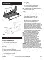
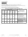
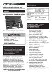
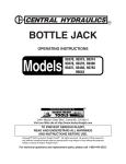
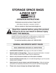
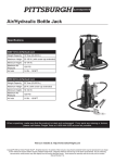
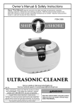
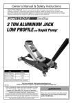
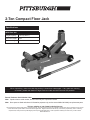
2-Ton Compact Floor Jack
Specifications
68783 Floor Jack
Weight Capacity
2 Tons (4,000 lb.)
Maximum Height
13 IN.
Minimum Height
5 IN.
When unpacking, make sure that the product is intact and undamaged. If any parts are missing
or broken, please call Harbor Freight Tools at 1-800-444-3353 as soon as possible.
Record Product’s Serial Number Here:
Note: If product has no serial number, record month and year of purchase instead.
Note: Some parts are listed and shown for illustration purposes only, and are not available individually as replacement parts.
Visit our website at: http://www.harborfreight.com
Copyright© 2009 by Harbor Freight Tools®. All rights reserved. No portion of this manual or any artwork contained herein may be reproduced in any shape
or form without the express written consent of Harbor Freight Tools. Diagrams within this manual may not be drawn proportionally. Due to continuing
improvements, actual product may differ slightly from the product described herein. Tools required for assembly and service may not be included.
Manual Revised 11f
Save This Manual
Safety Warnings
Keep this manual for the safety warnings and precautions,
assembly, operating, inspection, maintenance and cleaning
procedures. Write the product’s serial number on the
front page of the user’s manual (or month and year of
purchase if product has no number). Keep this manual and
the receipt in a safe and dry place for future reference.
WARNING Read all safety warnings
and instructions. Failure to heed
these markings may result in personal
injury and/or property damage.
1. Study, understand, and follow all instructions
before operating this device.
2. Do not exceed rated capacity (4,000 lb.).
Important Safety Information
3. Use only on hard, level surfaces.
In this manual, on the labeling, and all other
information provided with this product:
This is the safety alert symbol. It is used to
alert you to potential personal injury hazards.
Obey all safety messages that follow this
symbol to avoid possible injury or death.
DANGER indicates a hazardous situation which, if
not avoided, will result in death or serious injury.
4. Lifting device only. Immediately after lifting,
support the vehicle with appropriate means.
5. Do not move or dolly the vehicle while on the jack.
6. Failure to heed these markings may result in
personal injury and/or property damage.
7. Lift only areas of the vehicle as specified
by the vehicle manufacturer.
8. No alterations shall be made to this product.
9. Never work on, under or around a load
supported only by this device.
WARNING indicates a hazardous situation which, if
not avoided, could result in death or serious injury.
10. Do not adjust safety valve.
CAUTION, used with the safety alert symbol,
indicates a hazardous situation which, if not avoided,
could result in minor or moderate injury.
12. Keep clear of load while lifting and lowering.
11. Wear ANSI-approved safety goggles and
heavy-duty work gloves during use.
13. Lower load slowly.
14. Apply parking brake and chock
tires before lifting vehicle.
NOTICE is used to address practices
not related to personal injury.
15. Inspect before every use; do not use
if parts are loose or damaged.
CAUTION, without the safety alert symbol, is used to
address practices not related to personal injury.
16. Do not use for aircraft purposes.
17. The warnings, precautions, and instructions
discussed in this manual cannot cover all possible
conditions and situations that may occur. The
operator must understand that common sense and
caution are factors, which cannot be built into this
product, but must be supplied by the operator.
18. The brass components of this product contain lead,
a chemical known to the State of California to cause
cancer, birth defects (or other reproductive harm).
(California Health & Safety code § 25249.5, et seq.)
IMPORTANT! Before first use:
Check hydraulic oil level and fill to 1/4" below the fill
port as needed. Thoroughly test the Jack for proper
operation. If it does not work properly, bleed air
from its hydraulic system as stated on page 2.
SKU 68783
For technical questions, please call 1-800-444-3353
Page: 1
Adding Oil
Jack Components
1. Remove the Oil Fill Screw (Fig. 2).
2. Add qualified hydraulic oil of high grade into
the Fill Screw (Fig. 2) opening slowly until
the oil reaches the top of the oil fill hole.
Saddle
Lifting Arm
Handle
Socket
Note: Do not touch Handle when adding the hydraulic oil.
Oil Fill Screw
(Not Shown)
3. Replace the Fill Screw (Fig. 2).
Lifting
1. Park vehicle on a flat, level, solid, surface safely
away from oncoming traffic. Turn off the vehicle’s
engine. Place the vehicle’s transmission in “PARK”
(if automatic) or in its lowest gear (if manual).
Set the vehicle’s emergency brake. Then,
chock the wheels that are not being lifted.
Release Valve
Handle
Fig. 1
Handle Socket
2. Turn the Release Screw (located under the
Handle Socket) counterclockwise to lower the
Jack. Once the Jack is fully lowered, turn the
Release Screw firmly clockwise to close it.
3. Carefully position Saddle of Jack (Fig. 1) under the
vehicle manufacturer’s recommended lifting point. If
equipped, the Elevating Screw can be used to alter the
height of the jack’s saddle; it is adjusted by turning the
saddle clockwise or counterclockwise. (See vehicle
manufacturer’s owner’s manual for location of frame
lifting point when lifting only one wheel, and frame lifting
points when lifting entire front or rear end of vehicle.)
Oil Fill Screw
4. Pump the Handle until the top of the Jack’s Saddle
has nearly reached the vehicle lifting point.
Fig. 2
Hydraulic Unit
Note: The Jack should be positioned at 90° to the
vehicle’s lifting point to ensure the Jack’s Saddle
and vehicle lifting point are in alignment. If not,
reposition the Jack before lifting the vehicle.
5. To lift the vehicle, pump the Handle of the Jack.
Use smooth, full strokes for best results.
Setup and Operation
Attaching the Handle
1. Insert the Handle into the Handle Socket.
2. Turn Handle clockwise until Handle bases
is securely threaded into Socket.
Bleeding
1. Loosen the Oil Fill Screw (Fig. 2).
2. Insert the Handle into the Release Valve.
3. Turn the Handle (Fig. 1) counterclockwise to open valve.
4. Insert the Handle into the Handle Socket. Pump
the Handle (Fig. 1) up and down quickly for several
times to purge the air from the system.
6. Once the vehicle is raised, slide a jack stand of
appropriate capacity (not included) under the
proper lifting point referred to in the vehicle owner’s
manual. Always use two jack stands, position them
at the same point on each side of the vehicle.
WARNING! The rated capacity of jack stands is per pair,
not the individual capacities combined unless specifically
noted on the product by the jack stand manufacturer. Do
not exceed rated jack stand capacity. Ensure that the
vehicle support points are fully captured between the outer
lugs of both jack stands. Use a matched pair of jack stands
per vehicle to support one end only. Use 1 pair per vehicle
only. Failure to do so may result in sudden loss of load,
which may cause personal injury and/or property damage.
5. Tighten the Oil Fill Screw (Fig. 2).
SKU 68783
For technical questions, please call 1-800-444-3353
Page: 2
7. Center the vehicle’s lifting point(s) on the saddle of
the jack stand(s). Set the jack stand(s) according
to the manufacturer’s instructions, making
sure that they lock securely into position.
Note: Always set both Jack Stands at the same height.
8. Slowly turn the Handle counterclockwise to lower
the vehicle onto the saddle(s) of the jack stand(s).
Then, turn the Handle firmly clockwise to close it.
Lowering
1. Carefully remove all tools, parts, etc.
from under the vehicle.
2. Position the Saddle under the lifting point. Turn the
Release Screw firmly clockwise and pump the Handle
to raise the vehicle slightly above the saddles of the
jack stands. Then lower the Jack Stand Saddles to
their lowest position and carefully remove jack stands.
3. Slowly turn the Handle counterclockwise (never more
than two full turns) to lower the vehicle onto the ground.
4. Lower the Jack completely. Then, store in a
safe, dry location out of reach of children.
Inspection, Maintenance, & Cleaning
Procedures not specifically explained
in this manual must be performed
only by a qualified technician.
TO PREVENT SERIOUS INJURY FROM TOOL FAILURE:
Do not use damaged equipment. If abnormal
noise or vibration occurs, have the problem
corrected before further use.
1. Before each use, inspect the general condition of the
Jack. Check for broken, cracked, or bent parts, loose
or missing parts, and any condition that may affect the
proper operation of the product. If a problem occurs,
have the problem corrected before further use.
Do not use damaged equipment.
2. Before each use, thoroughly test the Jack
for proper operation prior to its actual use.
If the Jack appears not to be working properly,
follow Bleeding instructions on page 2.
3. Change hydraulic oil at least once every three years:
a. With the Jack fully lowered, remove the Oil
Fill Screw on the side of the Hydraulic Unit.
b. Tip the Jack to allow the old hydraulic oil to drain out
of the Housing completely, and dispose of the old
hydraulic oil in accordance with local regulations.
c. With the Jack upright, completely fill the Housing
with a high quality hydraulic oil (not included) until
the oil just begins to run out of the oil fill hole.
d. Open the Release Screw and pump the
Handle to bleed air from the system.
e. Recheck oil level and re-fill as needed.
f. Reinstall the Oil Filler Plug.
4. Wipe dry with a clean cloth. Then, store the
Jack in a safe, dry location out of reach of
children and other non-authorized people.
SKU 68783
For technical questions, please call 1-800-444-3353
Page: 3
Troubleshooting
To Prevent Serious Injury:
Use caution when troubleshooting a malfunctioning jack. Stay well clear of the supported load.
Completely resolve all problems before use. If the solutions presented in the Troubleshooting guide do not solve the
problem, have a qualified technician inspect and repair the jack before use.
After the jack is repaired: Test it carefully without a load by raising and lowering it fully,
checking for proper operation, BEFORE RETURNING THE JACK TO OPERATION.
DO NOT USE A DAMAGED OR MALFUNCTIONING JACK!
POSSIBLE SYMPTOMS
Jack will
not lift at
its weight
capacity
Saddle
lowers
under load
X
X
X
X
X
Pump
stroke
feels
spongy
Handle
Saddle will moves up
not lift all
when jack
the way
is under
load
Oil leaking
from filler
plug
X
X
X
X
SKU 68783
PROBABLE SOLUTION
(Make certain that the jack is not
supporting a load while attempting a
solution.)
Check that Release Valve is fully closed.
Bleed air from the system.
Valves may be blocked and may not
close fully. To flush the valves:
1. Lower the Saddle and securely
close the Release Valve.
2. Manually lift the saddle several inches.
3. Open the release valve and force the
saddle down as quickly as possible.
Jack may be low on oil.
Check the oil level and refill if needed.
Jack may require bleeding see instructions on page 2.
Unit may have too much
hydraulic oil inside, check fluid
level and adjust if needed.
For technical questions, please call 1-800-444-3353
Page: 4
PLEASE READ THE FOLLOWING CAREFULLY
THE MANUFACTURER AND/OR DISTRIBUTOR HAS
PROVIDED THE PARTS DIAGRAM IN THIS MANUAL
AS A REFERENCE TOOL ONLY. NEITHER THE
MANUFACTURER NOR DISTRIBUTOR MAKES ANY
REPRESENTATION OR WARRANTY OF ANY KIND
TO THE BUYER THAT HE OR SHE IS QUALIFIED TO
MAKE ANY REPAIRS TO THE PRODUCT OR THAT
HE OR SHE IS QUALIFIED TO REPLACE ANY PARTS
OF THE PRODUCT. IN FACT, THE MANUFACTURER
AND/OR DISTRIBUTOR EXPRESSLY STATES
THAT ALL REPAIRS AND PARTS REPLACEMENTS
SHOULD BE UNDERTAKEN BY CERTIFIED AND
LICENSED TECHNICIANS AND NOT BY THE BUYER.
THE BUYER ASSUMES ALL RISK AND LIABILITY
ARISING OUT OF HIS OR HER REPAIRS TO THE
ORIGINAL PRODUCT OR REPLACEMENT PARTS
THERETO, OR ARISING OUT OF HIS OR HER
INSTALLATION OF REPLACEMENT PARTS THERETO.
Parts List
Part
1
2
3
4
5
6
7
8
9
10
11
SKU 68783
Description
Handle
Hydraulic Ram
Oil Fill Plug
Handle Bracket
Release Valve
Overload Valve
Spring Washer (M12)
Nut (M12)
C-Ring
Spring
Cover Plate
Qty
1
1
1
1
1
1
4
4
1
1
1
Part
12
13
14
15
16
17
18
19
20
21
Description
Carrying Handle
Lifting Arm
Saddle
Wheel
Flat Washer
Caster
Spring Washer (M8)
Nut (M8)
Spring Washer (M10)
Nut (M10)
For technical questions, please call 1-800-444-3353
Qty
1
1
1
2
2
2
2
2
2
2
Page: 5
Assembly Diagram
SKU 68783
For technical questions, please call 1-800-444-3353
Page: 6
Limited 90 Day Warranty
Harbor Freight Tools Co. makes every effort to assure that
its products meet high quality and durability standards, and
warrants to the original purchaser that this product is free
from defects in materials and workmanship for the period of
90 days from the date of purchase. This warranty does not
apply to damage due directly or indirectly, to misuse, abuse,
negligence or accidents, repairs or alterations outside our
facilities, criminal activity, improper installation, normal
wear and tear, or to lack of maintenance. We shall in no
event be liable for death, injuries to persons or property,
or for incidental, contingent, special or consequential
damages arising from the use of our product. Some
states do not allow the exclusion or limitation of incidental
or consequential damages, so the above limitation of
exclusion may not apply to you. THIS WARRANTY IS
EXPRESSLY IN LIEU OF ALL OTHER WARRANTIES,
EXPRESS OR IMPLIED, INCLUDING THE WARRANTIES
OF MERCHANTABILITY AND FITNESS.
To take advantage of this warranty, the product or part must
be returned to us with transportation charges prepaid. Proof
of purchase date and an explanation of the complaint must
accompany the merchandise. If our inspection verifies the
defect, we will either repair or replace the product at our
election or we may elect to refund the purchase price if we
cannot readily and quickly provide you with a replacement.
We will return repaired products at our expense, but if we
determine there is no defect, or that the defect resulted
from causes not within the scope of our warranty, then
you must bear the cost of returning the product.
This warranty gives you specific legal rights and you may
also have other rights which vary from state to state.
3491 Mission Oaks Blvd. • PO Box 6009 • Camarillo, CA 93011 • (800) 444-3353
www.harborfreight.com