1
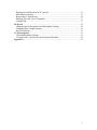
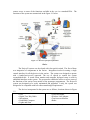
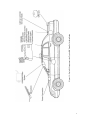
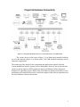
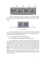
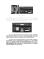
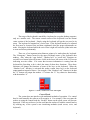
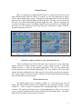
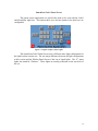
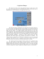
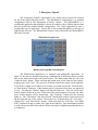
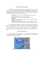
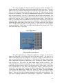
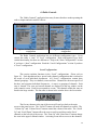
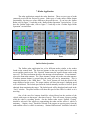
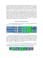
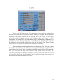
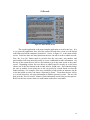
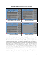
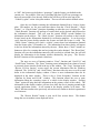
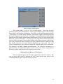
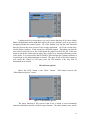
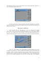
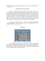
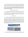
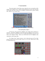
Project54
System User Manual
Consolidated Advanced Technologies for Law Enforcement Program (CATlab)
University of New Hampshire
Durham, NH 03824
(603) 862-1272
www.project54.unh.edu
Information within subject to change
Table of Contents
Table of Contents ................................................................................................................ i
Preface................................................................................................................................ 1
1. Introduction.................................................................................................................... 1
Basics .............................................................................................................................. 2
2. Using the System ............................................................................................................ 5
Touch Screen .................................................................................................................. 5
Voice Commands............................................................................................................ 6
Keyboard/Mouse............................................................................................................. 7
Control Heads ................................................................................................................. 8
Turning the System On and Off...................................................................................... 9
3. Patrol Screen ................................................................................................................ 11
Functions Common to Both Versions of the Patrol Screen .......................................... 11
Whelen Patrol Screen.................................................................................................... 11
SmartSiren/Code3 Patrol Screen................................................................................... 12
4. Application Manager ................................................................................................... 13
5. Emergency Signals....................................................................................................... 14
Whelen Serial Application............................................................................................ 14
Whelen Serial Light Bar Control Buttons................................................................. 14
Whelen Serial Siren Control Buttons........................................................................ 15
Whelen Serial Status Lights...................................................................................... 15
WhelenMPCO Application........................................................................................... 16
WhelenMPCO Light Bar Control Buttons................................................................ 16
WhelenMPCO Siren Control Buttons....................................................................... 17
WhelenMPCO Status Lights..................................................................................... 17
Code3 Application ........................................................................................................ 18
Code3 Light Bar Control Buttons ............................................................................. 18
Code3 Siren Control Buttons .................................................................................... 19
Code3 Status Lights .................................................................................................. 19
6. Radio Controls.............................................................................................................. 20
Local Configurations .................................................................................................... 20
Using Voice Commands to Operate a Local Radio Configuration............................... 21
State Configurations...................................................................................................... 21
Using Voice Commands to Operate a State Radio Configuration................................ 22
7. Radar Application ........................................................................................................ 24
Stalker Radar Operation................................................................................................ 24
Stalker Radar Application Status Lights................................................................... 25
Testing the Stalker Radar.......................................................................................... 26
Golden Eagle Radar Operation ..................................................................................... 26
Golden Eagle Radar Application Status Lights ........................................................ 27
Testing the Golden Eagle Radar ............................................................................... 27
8. GPS ............................................................................................................................... 29
9. Records ......................................................................................................................... 30
Running Records Based on Operator or Vehicle Information...................................... 31
i
Running Records Based on NCIC Queries................................................................... 33
Miscellaneous Queries .................................................................................................. 35
Requesting a Certified Copy......................................................................................... 36
Entering Text with Voice Commands........................................................................... 37
Getting Help.................................................................................................................. 37
10. Speech......................................................................................................................... 38
Changing Speech Recognition and Microphone Settings............................................. 38
Changing Speech Output Settings ................................................................................ 39
Special Functions .......................................................................................................... 39
11. System Options ........................................................................................................... 41
Color and Brightness Options....................................................................................... 41
Viewing Errors, System Status and Connected Modules ............................................. 42
Appendix A ....................................................................................................................... 43
ii
Preface
Project54 has two main goals. First, it aims to improve the ability of police to
collect and interpret data, as well as exchange data between mobile police units. Second,
it aims to provide a seamless way to integrate the controls of all of the equipment within
a police cruiser.
The system was developed at the University of New Hampshire’s (UNH)
Consolidated Advanced Technologies for Law Enforcement Program (CATlab), with
support from the US-DOJ (awards 1999-DD-BX-0082, 2001-LT-BX-K010 and 2002CK-WX-0104). This document is set up in a manner that will guide system users through
each of the Project54 applications. Within this document are detailed explanations of
how to navigate through the Project54 system, what each application is meant to do and
how to make each application perform its tasks.
This user manual is aimed at familiarizing the users of the Project54 system with
its functionality. It is a powerful system that will make vehicle operations easier and
safer for the user once he/she is accustomed to the system. This guide will act as a
learning tool as well as a reference for system users. The contents of this manual will
show and explain how the architecture of the software in this system is set up and how
that makes it very user-friendly.
1. Introduction
The Project54 system developed by CATlab integrates advanced computing and
communications equipment in police cruisers. It increases the functionality of the cruiser
and puts a wealth of information at the officers’ fingertips.
Speech is the preferred means of communication in the Project54 system. The
system accepts voice commands and responds using speech. The use of voice commands
reduces the need to type into a computer or operate control buttons that are not easily
accessible or that draw the officers’ attention from driving. The voice response feature of
the system means the officer does not have to shift his or her focus from the outside
environment to get feedback from the system. An easily accessible button on the steering
wheel is used to trigger speech processing.
The Project54 system provides the New Hampshire State Police and Department
of Motor Vehicles access to the central SPOTS database through a digital two-way radio.
This reduces the need to talk to a dispatcher who in turn would look up the requested data
and relay it back to the car. When the AVL functionality is enabled, the position of each
cruiser can be tracked using a GPS unit. This allows the setup of a computer aided
dispatch system as well as the introduction of mapping software in the cruisers. The
system is flexible, providing support for an array of commonly used devices (lights and
sirens, radar, video, etc.), each from multiple manufacturers. Finally, the system provides
1
remote access to some of the functions available in the car via a standard PDA. The
functions of the system are summarized in the figure 1-1 below.
Figure 1-1: Overview of Project54 functions
Basics
The Project54 system was developed with clear goals in mind. The first of these
was integration of components in the cruiser. Integration involved creating a single
control interface for all the devices in the cruiser. The system was designed to operate
with a hands-free/eyes-off approach. The use of speech to control the system
accomplished this. A touch screen monitor and computer keyboard setup is used for
additional interfaces to the system. The system also enables the officer to access some of
the functions of the cruiser from outside of the passenger compartment. The Project54
system was designed to be easily maintained and upgraded. Lastly, the system was
designed to be compatible with law enforcement budget requirements.
The devices incorporated in the system are as follows; locations shown in Figure
1-3.
• GPS
• Digital Two-Way Radio
• Microphone
• Embedded Computer
• Lights and Siren
• Video and Audio
• Wireless LAN Adapter
• Touch-screen Monitor
• Radar
Figure 1-2: Table of Devices Connected to Project54 System
2
3
Figure 1-3: Project54 Components in a Typical NH State Police Installation
Figure 1-4: Project54 aftermarket devices are connected via the CAN 2.0B network
The various devices in the cruiser (Figure 1-3) are linked and controlled with the
use of a data network (Figure 1-4), based on the CAN 2.0B standard commonly used in
automotive applications.
The manual provides details for the components and applications typically found in
system installations in police agencies in New Hampshire. However, the system software
can be run on any laptop or MDT running the Microsoft Windows 2000 or Microsoft
Windows XP operating systems. While some of the hardware details would differ in such
installations, this manual still provides a useful description of the software operations and
the basic hardware/software interactions.
4
2. Using the System
In order to properly and efficiently operate the system the user must become
familiar with how to interact with it. The user can operate the system a number of ways.
•
•
•
•
Touch screen
Voice commands
Keyboard/mouse
Normal control heads
Touch Screen
The touch screen is a fast and easy way for the user to navigate the system. The
boxes on the right-hand side of the screen are buttons that can be pressed to give
commands to the system. Only a slight tap is needed to press the buttons. Different
buttons operate in different ways depending on which device the button controls. There
are a few different button types.
•
•
•
•
Press and stick (toggle)
Press and hold
Changing title
Blue title (gray in older versions of the system)
A “Press and stick” button sticks down when it is pressed. The button can be
released by pressing it again. The function of that button will remain on while the button
is down.
Figure 2-1: Normal Button (left) and Depressed Button (right)
A “Press and hold” button needs to be held down in order for its function to be on.
When the button is released it will turn the function off.
The “Changing title” type of button is used specifically in the “Emergency
Signals” application. The title of the button shows the next selectable siren mode. Each
time it is pressed the title of the button changes.
5
Figure 2-2: Example of a Multiple Title Button “Siren Mode”
“Blue title” buttons lack the ability to be activated by a voice command. Buttons
with a black title can be activated by using voice commands. The “Blue title” buttons
should not be confused with normal “Black title” buttons that turn blue when they are
depressed.
Figure 2-3: Two Examples of Buttons Unable to be Activated by Voice Commands
Voice Commands
Giving voice commands to the system is easy and quick. Using voice commands
makes it safer to operate the system since it allows the user to keep his/her eyes on the
road while maintaining full functionality of the system. There are two different ways to
activate the voice command feature of the system.
•
•
Press and hold the “Talk” button on steering wheel
Press and hold the button to the right of mouse on the keyboard
In Ford vehicles, the “Talk” button is located on the steering wheel in the cruise
control cluster of buttons (Figure 2-4). Chevrolet vehicles have a red button located on
the steering wheel. The user must hold the button down, speak the command towards the
microphone and then let go of the button. The command will be performed by the
system. The same hold, speak, release process applies to the right mouse button if it is
activated (refer to the “Speech” application). If the user speaks a command that the
computer does not recognize it, it will let the user know. The title of any button with
black text is also a voice command for the button. Toggle buttons can be deactivated by
adding “off” to the button name voice command. For example, consider the “Strobes”
toggle button in Figure 2-1. If you held the “Talk” button on the steering wheel and said
“Strobes” the button would depress and the strobes would turn on and stay on. If you
then held in the “talk” button and said “Strobes Off” the button would release and the
strobes would turn off.
6
Figure 2-4: Two Different Buttons to Press for Voice Commands
Keyboard/Mouse
Although it is slower to use than the touch screen and voice commands, the
keyboard/mouse combination is a traditional way to operate the system. Figure 2-5
shows a picture of the “mouse” section of the keyboard. There is no physical mouse like
a regular computer. These keys are here to simulate them.
Figure 2-5: Mouse Section of Keyboard
The joystick is used to move the mouse arrow around. Once it is over the desired
object the left mouse button should be pressed. This process performs the same action as
pressing a button on the touch screen. While the physical controls might vary for other
notebook computers or MDTs, the operational specifics would remain the same.
Sometimes a field will require that information be entered. If the user wishes to
do this manually he/she can use the keyboard. All he/she has to do is move the mouse
arrow over the field box, press the left mouse button and then enter the text. If there are
multiple fields the user can use the “tab” key to toggle between them. The “tab” key
toggles through all text entry fields on the screen. Pressing shift and tab at the same time
will toggle through the fields in reverse order.
7
Figure 2-6: Keyboard Setup
The setup of the keyboard is much like a keyboard on a regular desktop computer,
only on a smaller scale. The mouse control section of the keyboard is on the bottom
center section of the keyboard. Simply using the keyboard will get the user used to its
setup. The keyboard is mounted on a swivel arm. If the keyboard needs to be adjusted
the arm must be loosened first and then retightened when the proper adjustments are
made. Moving the keyboard while the swivel arm is tight will cause the joints in the arm
to wear and loosen permanently.
There are a few important miscellaneous points to be made about the keyboard.
The “Emergency” button located in the upper left-hand corner of the keyboard does
nothing. Also, when the “caps locked”, “number lock” or “scroll lock” functions are
activated a red status light will become visible in the lower left corner of the LCD screen
indicating an active status. If it seems that incorrect information is coming from the
keyboard the first thing to do is check the status of these three functions. These three
functions will change the functions of some of the keys on the keyboard. When the
“Number Lock” function is activated this makes certain letter keys on the keyboard
output numbers instead of letters. For example, if the “Number Lock” function is on then
the “U” button will output the number “4” because the “U” key shares its functionality
with the number “4.”
Figure 2-7: “SCR”, “NUM” and “CAP” status lights
Control Heads
The system does not interfere with traditional methods of operation. If a control
head is used manually the software will recognize it. For example, if the user turns the
strobes on using the control head the “Strobes” button on the touch screen will become
depressed. If the user wishes to, he/she could turn the strobes off with the control head or
by utilizing any of the system’s user interfacing methods (touch screen, voice, and
keyboard).
8
Figure 2-8: Control Head status light off/on
Figure 2-8 shows the Control Head status light off (red) and on (blue) which
appears in some device control screens. When a control head is communicating properly
with the software it will turn blue. The light is red when there is no communication
between the software and the control head.
Turning the System On and Off
It is important that the system is properly turned on and off. Turning the system
on is simple. There are two switches on the front of the console. The bottom button
turns on the control heads and the top button turns on the computer, monitor and IDB
network. They should both be turned on upon vehicle startup. The computer will turn on
and load. The Project54 software should start automatically. If it does not the user must
double click the icon below.
Some vehicle installations have one power switch instead of two. If there is only
one switch, then that one switch controls the computer, monitor, and IDB network, and
the rest of the equipment is either directly wired to the battery, or powered on/off using
the ignition key.
Figure 2-9: P54 Icon
Turning the system off correctly is vital to proper system operation. To power
off, go back to the main screen and hit the “Exit” button. Next, the following buttons will
appear.
Figure 2-10: Exit Options
If the user wishes to power down for good he/she should hit the “Power Off”
button. This will safely power down the entire computer system. The “Exit” button will
just exit the Project54 application, leaving the computer on. The “Cancel” button will
9
cancel the exit options and return to the application. If the system is manually powered
down without properly shutting off the computer it may damage the computer and the
valuable information saved on the hard drive.
10
3. Patrol Screen
This is a commonly used application because it is versatile and can be used to do
many different things while the officer is on patrol. It is the first application an officer
will see when starting up the system. The purpose of this application is to give the officer
quick access to radar, radio and lights and siren functions. The user can view speeds on
the radar, view radio channels and operate the lights and siren. There are currently two
versions of the patrol screen. The Whelen Patrol Screen is used if there is a Whelen light
bar on the car. The SmartSiren/Code3 Patrol Screen is used if there is either a Code3 or
SmartSiren light bar on the car.
Figure 3-1: Whelen Patrol Screen
Figure 3-2: SmartSiren/Code3 Patrol Screen
Functions Common to Both Versions of the Patrol Screen
There are buttons to go back to the main screen (section 4), access emergency
signals (section 5), records controls (section 9), radar controls (section 7), and radio
controls (section 6). These are all separate applications. The user can perform more
specific functions in each individual application. The “scan” button is one of the radio
control functions mentioned in the radio controls section that scans the radio channels.
The “Front Antenna” and “Rear Antenna” buttons are radar control functions that toggle
between front and rear radar antennas.
Whelen Patrol Screen
The Whelen patrol screen is shown in figure 3-1. The bottom three rows of
buttons and “Rear Floods” buttons are all explained in the “Emergency Signals” section
(section 5). When a button is depressed the corresponding lights or siren will be
activated. The patrol screen takes pieces of other applications to make it a very quick
way to access the important and necessary functions needed during patrol. For greater
detail on the functions see their respective sections.
11
SmartSiren/Code3 Patrol Screen
This patrol screen application was specifically made to be used with the Code3
and SmartSiren light bars. The bottom three rows and one button in the third row are
configurable.
Figure 3-3: Lights Graphics Status Llights
The SmartSiren/Code3 Patrol Screen uses a different status light configuration for
the light bar than version one. The one major difference between the light configuration
in this version and the Whelen Patrol Screen is the use of signal lights. The “F” status
lights also stand for “Flashers.” These lights are usually positioned on the rear deck of
the car.
12
4. Application Manager
The “home base” of the system is the application manager or main screen. All of
the system’s major applications are accessible from this screen. The date and time are
displayed here as well as a button for every application in the system.
Figure 4-1: Main Screen window
The Project54 software will bring the user to the patrol screen when it boots up.
As discussed earlier, this application allows control of lights, siren and radar functions all
on one convenient screen. The “Emergency Signals” button brings the user to all of the
lights and siren controls. The “Radio Controls” button sends the user to the radio
controls application. This application has made channel surfing the radio much faster and
safer. Pressing the “Radar” button sends the user to an application that houses all radar
controls on an easy-to-read screen. The “GPS” button lets the user view their vehicle’s
global positioning coordinates. Pressing the “Video” button accesses the video
application that controls digital video recordings and playback (if available). The
“Records” button is right below the “GPS” button. It allows the user access to a powerful
application that assists the user in running records checks, vehicle checks, NCIC
information and other miscellaneous information upon demand if available.
The “Speech” and “System Options” buttons send the user to applications that
allow users and installers to make changes to system settings. The user can find
brightness/night colors settings in the “System Options” section. There, they can change
brightness levels and screen colors to better suit night viewing. Voice and speech settings
can also be changed in the “Speech” application, making the system very customizable.
13
5. Emergency Signals
The “Emergency Signals” application is very useful since it houses the controls
for all of the lights and siren devices. The WhelenSerial configuration is a standard
configuration used by NH Department of Safety vehicles. The WhelenMPCO is a
configurable application that should be selected for vehicles with a Whelen light bar that
does not match the standard NHSP configuration. The Code3 application is also a
configurable type of application. Please skip to the section that applies to the type of
light bar that you have. The WhelenSerial section is first, followed by the WhelenMPCO
and Code3 sections.
WhelenSerial Application
Figure 5-1: Whelen Serial Application
Whelen Serial Light Bar Control Buttons
The WhelenSerial application is a standard, non-configurable application. In
figure 5-1 the first two buttons from the top, left-hand side of the button cluster are links
back to the main screen and to the patrol screen. The third button from the left is the
“Lights & Siren” button. When activated this button turns on the front and rear strobes,
wigwags and “wail” siren. The next row of button controls the strobes on the light bar.
If you desire a single set of strobes to be on then you would activate the “Front Strobes”
or “Rear Strobes” functions. Other buttons may be depressed while these are depressed
as well. Pressing the “Strobes” button will turn all strobes on. Only one of the three
strobes buttons can be on at once. When one of the strobes buttons is pressed, any other
active strobes buttons will be deactivated. The “Wigwags” button turns the wigwag
lights on. The “Takedowns” and “Rear Floods” buttons turn on their respective devices
for the front and rear of the vehicle. Below that row of buttons there are “Left Alley”,
“Right Alley”, and “Siren Mode” buttons. When activated, the “Left Alley” and “Right
Alley” buttons will turn on either alley light on the light bar. Note that button positions
in your vehicle may differ from others with the same type of lightbar depending on how it
is configured.
14
Whelen Serial Siren Control Buttons
The button to the right of the “Right Alley” button in figure 5-1 covers four siren
functions. The current siren mode is displayed on the left-hand side of the screen in the
“siren” window. The next selectable siren mode will be displayed on the button itself, so
the button will change titles when the user touches it. The button is located to the right of
the “Right Alley” button. Below are the four siren modes.
Manual mode – This mode is the normal manual mode. Pressing the
siren button will turn on the siren until it is released.
Radio mode – This mode plays the digital radio over the siren
loudspeaker.
HF mode – This is the hands free mode. The siren can be activated using
the horn on the steering wheel.
PA mode – This allows the user to talk over the siren loudspeaker. The
“air horn” type siren can be activated using the horn on the steering wheel.
The next three buttons are the siren control buttons. Choosing “Wail”, “Yelp”, or
“Piercer” will activate their respective siren sound. These buttons stay activated until
they are pressed again. The “Air Horn” button is a “press and hold” button that sounds
the vehicle’s air horn when depressed until the button is let go. The “Manual Siren”
button is also another “press and hold” button that plays the selected siren sound until it is
let go.
Whelen Serial Status Lights
The status lights on the left-hand side of the screen are an important part in
verifying that the system is working properly. The status lights for each type of light bar
are all slightly different from each other.
Figure 5-2: Status Lights Active on Whelen Serial Application
15
The system in figure 5-2 has activated the wigwags, strobes, takedowns, rear
floods and wail type siren. The status lights are set up in a similar configuration to the
light bar on top of the vehicle. Starting from the front and working towards the back of
the light bar, the white “W” light indicates that the wigwags are operational. This light
will alternate between the two W’s indicating that they are indeed flashing. The blue “S”
lights indicate that the strobes are operating. The lights will turn blue from left to right
and turn off in the same order, like the motion of an actual strobe light bar. The “T”
lights are the takedown status lights. These lights will both be a solid white when the
takedowns are operating. Next, there are the left alley and right alley lights. These are
located on the side of the light bar. When the alley lights are operational their status
lights will be white as well. Located in the rear of the light bar there is another strobe bar
similar to the front strobes. Lastly, there are the rear floods. When the rear floods are
operating the status lights will remain a solid blue.
WhelenMPCO Application
Figure 5-3: WhelenMPCO Application
WhelenMPCO Light Bar Control Buttons
The WhelenMPCO application is a configurable application. In figure 5-3 the
first two buttons from the top, left-hand side of the button cluster are links back to the
main screen and to the patrol screen. The next row of buttons controls the strobes on the
light bar. If you desire a single set of strobes to be on then you would activate the “Front
Strobes” or “Rear Strobes” functions. Other buttons may be depressed while these are
depressed as well. Pressing the “Strobes” button will turn all strobes on. Only one of the
three strobes buttons can be on at once. When one of the strobes buttons is pressed, any
other active strobes buttons will be deactivated. The “Wigwags” button turns the wigwag
lights on. The “Takedowns” and “Rear Floods” buttons turn on their respective devices
for the front and rear of the vehicle. Below that row of buttons there are “Left Alley” and
“Right Alley” buttons. When activated, the “Left Alley” and “Right Alley” buttons will
turn on either alley light on the light bar. Between the “Left Alley” and “Right Alley”
buttons is the signal button. The signal button operates the traffic advisor lights.
Pressing this button will activate the function displayed on the button and also toggle to
the next type of lighting sequence. The four types of lighting sequences are “Signal
16
Right”, “Signal Left”, “Signal Both” and “Flasher.” Note that button positions in your
vehicle may differ from this configuration depending on how it is configured.
WhelenMPCO Siren Control Buttons
The “Siren” button to the right of the “Yelp” button in figure 5-3 covers four siren
functions. The current siren mode is displayed on the left-hand side of the screen in the
“siren” window. The next selectable siren mode will be displayed on the button itself, so
the button will change titles when the user touches it. Pressing the “Siren” button turns
the selected siren on. The siren can also be operated in four different modes. Below are
the four siren modes.
Manual mode – This mode is the normal manual mode. Pressing the
siren button will turn on the siren until it is released.
Radio mode – This mode plays the digital radio over the siren
loudspeaker.
HF mode – This is the hands free mode. The siren can be activated using
the horn on the steering wheel.
PA mode – This allows the user to talk over the siren loudspeaker. The
“air horn” type siren can be activated using the horn on the steering wheel.
The “Air Horn” button is a manual button that sounds the vehicle’s air horn when
depressed until the button is let go. The “Manual Siren” is also another manual button
that sounds a siren when depressed until it is let go.
WhelenMPCO Status Lights
The status lights on the left-hand side of the screen are an important part in
verifying that the system is working properly. The status lights for each type of light bar
are all slightly different from each other.
Figure 5-4: Active Status Lights for the WhelenMPCO Application
17
The system in figure 5-4 has activated the wigwags, strobes, takedowns, rear
floods, right and left alley lights, traffic advisor lights and a wail type siren. The status
lights are set up in a similar configuration to the light bar on top of the vehicle. Starting
from the front and working towards the back, the white “W” light indicates that the
wigwags are operational. This light will alternate between the two W’s indicating that
they are indeed flashing. The blue “S” lights indicate that the strobes are operating. The
lights will turn blue from left to right and turn off in the same order, like the motion of an
actual strobe light bar. The “T” lights are the takedown status lights. These lights will
both be a solid white when the takedowns are operating. Next, there are the left alley and
right alley lights. These are located on the side of the light bar. When the alley lights are
operational their status lights will be white as well. Located in the rear of the light bar
there is another strobe bar similar to the front strobes. Also in the rear of the car, there
are the rear flashers. Finally, there are traffic advisor lights on the setup as well. They
turn yellow when they are operating.
Code3 Application
Figure 5-5: Code3 Light Bar Application
Code3 Light Bar Control Buttons
The Code3 application is a configurable application. In figure 5-5 the first two
buttons are links back to the main screen and to the patrol screen. The next row of
buttons controls the strobes on the light bar. If you desire a single set of strobes to be on
then you would activate the “Front Strobes” or “Rear Strobes” functions. Other buttons
may be depressed while these are depressed as well. Pressing the “Strobes” button will
turn all strobes on. Only one of the three strobes buttons can be on at once. The
“Wigwags” button turns the wigwag lights on. The “Takedowns” and “Rear Flashers”
buttons turn on their respective devices for the front and rear of the vehicle. Below that
row of buttons there are “Left Alley” and “Right Alley” buttons. When activated, the
“Left Alley” and “Right Alley” buttons will turn on either alley light on the light bar.
To the right of the “Right Alley” button is the “Lights Off” button. Pressing this button
will deactivate all running lights. Below the alley buttons are traffic advisor control
buttons. There are four types of lighting sequences for the traffic advisor light bar. The
four types of lighting sequences are “Signal Right”, “Signal Left”, “Signal Both” and
18
“Flasher.” The right button on the top row is a traffic advisor toggle button. When
pressed the current function on the button title is performed and the next title will be
displayed. This allows for one button to be able to perform four functions. For example,
in figure 5-5 the “Signal Left” function would be performed if the button was pressed.
The title of the button would change to “Signal Right.” Note that button positions in your
vehicle may differ from this configuration depending on how it is configured.
Code3 Siren Control Buttons
The bottom row of buttons in figure 5-5 deal with siren functions. The “Wail”
and “Yelp” buttons turn on wail and yelp type sirens. The “Manual Siren” is a manual
button that sounds a siren when depressed until it is let go.
Code3 Status Lights
The status lights on the left-hand side of the screen are an important part in
verifying that the system is working properly. The status lights for each type of light bar
are all slightly different from each other.
Figure 5-6: Active Status Lights for the Code3 Application
The system in figure 5-6 has activated the wigwags, strobes, takedowns, rear
floods, left and right alley lights and traffic advisor lights. The status lights are set up in a
similar configuration to the light bar on top of the vehicle. Starting from the front and
working towards the back, the white “W” light indicates that the wigwags are
operational. This light will alternate between the two W’s indicating that they are indeed
flashing. The blue “S” lights indicate that the strobes are operating. The lights will turn
blue from left to right and turn off in the same order, like the motion of an actual strobe
light bar. The “T” lights are the takedown status lights. These lights will both be a solid
white when the takedowns are operating. Next, there are the left alley and right alley
lights. These are located on the side of the light bar. When the alley lights are
operational their status lights will be white as well. Located in the rear of the light bar
there is another strobe bar similar to the front strobes. Also in the rear of the car, there
are the rear flashers. Finally, there are signal lights on the setup as well. They turn
yellow when they are operating.
19
6. Radio Controls
The “Radio Controls” application has many features that have made operating the
radio a simpler and safer task for officers.
Figure 6-1: Example of a Local Radio
Configuration
Figure 6-2: Example of a State Radio
Configuration
The Radio Controls application has two different configuration types. Every
vehicle has either a “state” or “local” configuration. Both configuration types share
certain functionality, but there are differences. Skip to the “State Configurations” section
if you have a “State” configuration. Read the “Local Configurations” section if you have
a “Local” configuration.
Local Configurations
This section explains functions in the “Local” configurations. Please refer to
figure 6-1. Each department has a special radio channel configuration that is tailored to
the needs of each individual department. All “Local” configurations contain three
channel groupings. They are channels, zones and lists. Channels are the most specific of
the three and represent individual frequencies. A zone is a grouping of channels. Each
zone is lettered. The zone and current channel are displayed in the top window on the
radio controls screen. Each list corresponds to a zone. The channels within the zone are
listed in the large window. The list name is shown in the window above the list window.
Figure 6-3: Zone/Channel Listing
The first two buttons at the top of the screen will send you back to the main
screen or the patrol screen. The “List All” button will make all channels accessible. The
“Volume Up” and “Volume Down” buttons control the volume of the radio. The “Scroll
Up” and “Scroll Down” buttons allow the user to scroll up and down on the list of
channels on the left side of the screen. The “Zone Up” and “Zone Down” buttons change
the zone in the upper left-hand window. Activating a zone allows access to the channels
20
in that zone. The “List Up” and “List Down” buttons scroll through the lists of channels
available to each car. The “Channel Up” and “Channel Down” buttons switch through
the channels in the zone. When a channel or zone switch is made the new information
will be displayed in the upper display window as in figure 6-3. Figure 6-3 shows a zone
and channel listing. The “J” stands for the zone. “LP South” stands for the channel.
The “Scan” function works like the scan button on the radio control head. The
radio will scan the channel list for activity on other channels. If there is activity the radio
will switch to the active channel. The “Scan List” function activates scan list
programming mode. The “Select” button is used in scan list programming mode and
selects specific radio channels to be added to the scan list. In the bottom right-hand
corner of the screen you will see the “Encrypt” button. This function encrypts signals
between two users communicating over the radio just like the encrypt function on the
control head.
There are six status lights to the right of the display windows. The top button is
labeled “Scan” and it indicates when the radio is scanning for active channels. When
information is being sent to or from the radio the “XMIT” and “Busy” lights will light up
temporarily until the radio is ready. The “Scan List” light will turn on when the radio is
in scan list programming mode. The “NPRI” and “PRI” lights indicate whether the
selected channel is a priority or non-priority channel when the “Scan” function is on.
Activity on “Priority” channels will override activity on “Non-priority” channels.
Using Voice Commands to Operate a Local Radio Configuration
Radio channels can be accessed with voice commands. The only channels
accessible by voice commands are the channels in the current zone, displayed in the top
window. You can toggle through zones with the buttons on the touch screen or by
speaking “Zone Up” or “Zone Down” while the “Talk” button is depressed. If you want
to tune in to a specific channel in a zone, simply speak the name of the channel while a
“Talk” button is depressed then let go of the button. If you want to change the viewable
list on the screen hold down the “Talk” button and speak the word “list” and then the list
name. Let go of the “Talk” button.
State Configurations
This section explains functions in the “State” configurations. Please refer to
figure 6-2. The “State” configuration is tailored to the needs of the state police and
contains three channel groupings. They are channels, zones and troops. Channels are the
most specific of the three and represent individual frequencies. A zone is a grouping of
channels. Each zone is lettered. The zone and current channel are displayed in the top
window on the radio controls screen. Each list corresponds to a zone. The channels
within the zone are listed in the large window. The list name is shown in the window
above the list window.
21
Figure 6-4: Troop/Channel Listing
The first two buttons at the top of the screen will send you back to the main
screen or the patrol screen. The “All Zones” button will make all channels accessible.
The “Volume Up” and “Volume Down” buttons control the volume of the radio. The
“Scroll Up” and “Scroll Down” buttons allow the user to scroll up and down on the list of
channels on the left side of the screen. The “Zone Up” and “Zone Down” buttons change
the zone in the upper left-hand window. Activating a zone allows access to the channels
in that zone. The “Troop Up” and “Troop Down” buttons scroll through the lists of
channels available to each car. The “Channel Up” and “Channel Down” buttons switch
through the channels in the zone. When a channel or zone switch is made the new
information will be displayed in the upper display window as in figure 6-4. Figure 6-4
shows a zone and channel listing. The “E3” stands for the zone. “TRP E” stands for the
channel.
The “Scan” function works like the scan button on the radio control head. The
radio will scan the channel list for activity on other channels. If there is activity the radio
will switch to the active channel. The “Scan List” function activates scan list
programming mode. The “Select” button is used in scan list programming mode and
selects specific radio channels to be added to the scan list. In the bottom right-hand
corner of the screen you will see the “Encrypt” button. This function encrypts signals
between two users communicating over the radio just like the encrypt function on the
control head.
There are seven status lights to the right of the display windows. The top button
is labeled “Scan” and it indicates when the radio is scanning for active channels. The
“Encrypt” light will turn on when the radio is encrypting information, when information
is being sent to or from the radio the “XMIT” and “Busy” lights will light up temporarily
until the radio is ready. The “Scan List” light will turn on when the radio is in scan list
programming mode. The “NPRI” and “PRI” lights indicate whether the selected channel
is a priority or non-priority channel when the “Scan” function is on. Activity on
“Priority” channels will override activity on “Non-priority” channels.
Using Voice Commands to Operate a State Radio Configuration
Radio channels can be accessed with voice commands. The only channels
accessible by voice commands are the channels in the current zone, displayed in the top
window. You can toggle through zones with the buttons on the touch screen or by
speaking “Zone Up” or “Zone Down” while the “Talk” button is depressed. If you want
to tune in to a specific channel in a zone, simply speak the name of the channel while a
“Talk” button is depressed then let go of the button. If you want to change the viewable
list on the screen hold down the “Talk” button and speak the word “Switch Troop” and
22
then the troop letter followed by its phonetic alphabet word. Let go of the “Talk” button.
The phonetic alphabet can be found in appendix A.
23
7. Radar Application
The radar application controls the radar functions. There are two types of radar
commonly used with the Project54 system. Both types of radar utilize similar button
functionality, but there are some differences between the two. If you have the Stalker
Radar, refer to figure 7-1 and skip to the “Stalker Radar Operation” section below. If you
have the Golden Eagle radar, refer to figure 7-2 and skip to the “Golden Eagle Radar
Operation” section below.
Figure 7-1: Radar Application for Stalker Radar
Figure 7-2: Radar Application for Golden Eagle
Radar
Stalker Radar Operation
The Stalker radar application has a few different modes similar to the modes
found on the control head. The first two buttons on the top are links back to the main
screen and the patrol screen. The “Squelch” button turns the squelch feature on the radar
on or off. The first two buttons down are the antenna selection buttons. “Front Antenna”
selects the front radar antenna. The “Rear Antenna” button selects the rear radar antenna.
If neither antenna button is pressed then the radar will not be transmitting. This is
commonly known as the “Hold State.” The “Lock” button will lock the speed of the
target displayed on the screen. The target window will show the target’s changing speed
as it is monitored. The locked speed must be locked manually in order to freeze a speed
obtained from monitoring the target. The locked speed will be displayed and saved in the
“Lock” window. The patrol window will show the speed of the officer’s vehicle as it is
traveling.
One of the next five buttons should be selected based on the position of the
vehicle with respect to the targets’ direction of travel. This will ensure a proper reading
while the radar is recording speeds. On the Stalker radar screen “Station. Closing”
should be selected if the targets are approaching the radar and the officer’s vehicle is
stationary. “Station. Away” should be selected if the targets are moving away from the
radar and the officer’s vehicle is stationary. “Station. Bidirectional” should be selected if
24
the officer’s vehicle is taking readings of cars headed in both directions from a stationary
position on the side of the road. “Same Mode” would enable the officer to read a target’s
speed if the officer and target were both moving in the same direction. Selecting the
“Opposit. Mode” button would enable the officer to read a target’s speed if the officer
and target were moving in opposite directions. Only one of these five modes can be
selected at once. “Fast Mode” activates the fast mode function on the radar unit itself.
Fast mode is used when the radar is seeing multiple objects at once. Normally, the radar
will pick up the largest traveling object (strongest signal) and display its speed. In fast
mode the radar will display the speed of the fastest moving object in its range and display
it in the “Locked” display window. The largest vehicle’s speed will be displayed in the
left display window. The “Patrol 5/20” button will toggle between “Patrol 20” and
“Patrol 5” when pressed. Take note that the button titles such as “Station. Closing” and
“Opposit. Mode” are abbreviated. The full words such as “stationary” or “opposite”
should be spoken when giving a voice command to the system.
Stalker Radar Application Status Lights
As seen on the left side of the screen in figure 7-1 there are status lights and speed
windows. An active status light will turn green.
Figure 7-3: Functional Status Lights for Stalker Radar
On the Stalker radar screen the “Audio”, “Range” and “Bright” buttons control
the volume, range, and brightness levels of the radar and correspond to the meters on the
left of the screen. Pressing each of these buttons will increase their respective meter
values. The brightness meter on the screen displays how bright the numbers on the radar
unit are. In the Stalker application the user can give a voice command to change the
“Audio”, “Range” and “Bright” meters. They can jump directly to the level they want by
saying “Audio Two” or “Bright Three” for example.
The “FO”, “RF”, and “LV” lights will only light up during testing or when there
is a problem. The “RF” light may turn on and off periodically which is normal. Please
inform maintenance personnel if the “LV” light turns on or the “RF” light stays on.
Figure 7-4: Operational Status Lights for Stalker Radar
25
The antenna status lights indicate which radar antenna is being used for speed
readings. “F” and “R” stand for front and rear antenna. The “CL” and “AW” lights stand
for “closing” and “away.” These indicate the stationary modes that the radar can operate
in. When the “Station. Bidirect.” mode is selected both lights will turn green. The “SA”
and “OP” lights stand for “same” and opposite” mode. These indicate the moving modes
that the radar can operate in.
Testing the Stalker Radar
Activating the “Test” function runs a self-test on the radar unit in order to insure
that it is in correct working order. If the unit is in proper working order it will display the
word “PASS” on the control head. Please refer to the radar’s operations manual for other
testing instructions.
Golden Eagle Radar Operation
The Golden Eagle radar application has modes similar to the modes found on the
control head. The first two buttons on the top are links back to the main screen and the
patrol screen. The “Squelch” button turns the squelch feature on the radar on or off. The
first two buttons down are the antenna selection buttons. “Front Antenna” selects the
front radar antenna. The “Rear Antenna” button selects the rear radar antenna. If neither
antenna button is pressed then the radar will not be transmitting. This is commonly
known as the “Hold State.” The “Lock” button will lock the speed of the target displayed
on the screen. The target window will show the target’s changing speed as it is
monitored. The locked speed must be locked manually in order to freeze a speed
obtained from monitoring the target. The locked speed will be displayed and saved in the
“Lock” window. The patrol window will show the speed of the officer’s vehicle as it is
traveling.
One of the next three buttons should be selected based on the position of the
vehicle with respect to the targets’ direction of travel. This will ensure a proper reading
while the officer is recording speeds. On the Golden Eagle radar screen “Station. Mode”
should be selected if the user’s vehicle is stationary. “Opposit. Mode” should be selected
if the officer’s vehicle is moving and the targets are headed in the opposite direction as
the vehicle. “Same Mode” would enable the officer to read a target’s speed if they were
both moving in the same direction. Only one of these three modes can be selected at
once. “Faster Slower” switches between the faster and slower modes on the radar unit
itself. Pressing and holding the “Reset” button for a few seconds will clear all values
from the display windows, and release all depressed buttons in the application. The radar
unit will also perform a self-test. Take note that the button titles such as “Station. Mode”
and “Opposit. Mode” are abbreviated. The full word such as “stationary” or “opposite”
should be spoken when giving a voice command to the system.
Holding the “Faster Slower” button in the application is the same as pressing and
holding the “Fastest” switch on the radar unit. While the button is depressed the speed of
the fastest vehicle will be displayed in the “Locked” window. The speed of slower
26
vehicles will be displayed in the “Target” window. The radar will return to normal
operation after about two seconds.
Golden Eagle Radar Application Status Lights
Figure 7-5: Functional Status Lights and Windows for Golden Eagle Radar
On the Golden Eagle radar screen the “Audio Up/Down” and “Range Up/Down”
buttons control the volume and range levels of the radar and correspond to the windows
on the left of the screen. Pressing each of these buttons will increase or decrease its
respective value in the status window. These functions can also be controlled using voice
commands. Saying “Audio Up” or “Range Down” are examples of how the Golden
Eagle radar range and audio functions are operated. The user cannot select specific range
and audio levels. When using the voice commands, he/she must move up or down one
level at a time.
The “RF” and “LV” lights will only light up when there is a problem. The “RF”
light may turn on and off periodically which is normal. Please inform maintenance
personnel if the “LV” light turns on or the “RF” light stays on.
Figure 7-6: Operational Status Lights for the Golden Eagle Radar
The antenna status lights indicate which radar antenna is being used for speed
readings. “F” and “R” stand for front and rear antenna. The “CL” and “AW” lights stand
for “closing” and “away.” These indicate the stationary modes that the radar can operate
in. When the “Station. Bidirect.” mode is selected both lights will turn green. The “SA”
and “OP” lights stand for “same” and opposite” mode. These indicate the moving modes
that the radar can operate in.
Testing the Golden Eagle Radar
Depressing the “Test” function runs a self-test on the radar unit in order to insure
that it is in correct working order. The radar will complete a lamp and internal test then
return to normal operation. If the unit is in proper working order the “Target” window
will display “32” on the control head. This test is to verify that the unit’s LEDs and
27
internal accuracy are in proper working order. Refer to the radar’s operations manual for
other testing instructions.
28
8. GPS
Figure 8-1: GPS Screen
Above is the GPS data screen. This application receives periodic readings from
the GPS unit located on the back of the vehicle. When it is available, the information is
displayed in the display windows on the left-hand side of the screen. As the vehicle
moves the latitude, longitude, velocity, and heading readings will change. If AVL
functionality is enabled, the GPS information will be automatically transmitted to a
headquarters server. The report frequency is controlled by an algotithm which considers
the distanced moved and the elapsed time since the last report. The “Report” button
allows the user to report GPS coordinates to headquarters on demand.
The fields along the bottom indicate the GPS data quality. The “GPS Age” shows
the number of seconds since the GPS device last supplied information. If this number is
greater than a few seconds, there is probably something wrong with the GPS connection.
The “Fix” field show the type of fix: DGPS or GPS (DGPS is more accurate). The
“Satellites” field shows the number of satellites currently visible to the GPS unit (at least
4 are needed). Finally, the “Error Multiplier” gives a numerical rating of the accuracy of
the location. This should generally be 2 or less.
29
9. Records
Figure 9-1: Main Records Screen
The records application is the most complex application as seen by the user. It is
a very powerful application since all of the queried records data is sent over the digital
radio and stored on the computer’s hard drive. Above, in figure 9-1, is the main records
screen. From here there are many directions the user can take in order to obtain records.
First, the “Log On” button must be pressed after the user name, unit number, and
password have all been entered in order to access confidential records information. On
the top of the screen the user will see the buttons to go to the main screen or the patrol
screen. Depending on how the user desires to obtain specific records, he or she must
choose one of the four buttons in the second, third or fourth rows. Each function brings
the user to another screen where he or she can search for records based on what the
button indicates. For example, if the user would like to find records on someone who he
or she has pulled over they can choose “Operator by Name.” From there the user will go
to a screen where they can enter information to find the person’s records. The user can
then press the “Review results” button to fetch information saved from previous queries.
Below are the four screens relative to each button on the above screenshot.
30
Running Records Based on Operator or Vehicle Information
Figure 9-2: Operator by Name and D.O.B.
Figure 9-3: Operator by OLN
Figure 9-4: Vehicle by Plate
Figure 9-5: Vehicle by VIN
Above are four screenshots, each corresponding to a button on the main records
screen. Starting with the “Operator by Name and D.O.B.” screen one can see that
information needs to be entered in the boxes on the upper left hand side of the screen.
The information can be entered either manually with the keyboard or using the voice
command feature of the system. The “Operator by Name and D.O.B.” screen, figure 9-2,
allows the user to search for information on that person based on the person’s name and
date of birth. Figure 9-3 shows the “Operator by OLN” screen. This allows the user to
obtain information based on their operator license number. Figure 9-4 shows the
“Vehicle by Plate” screen. This screen allows the user to obtain information on a vehicle
based on license plate information. Figure 9-5 shows the “Vehicle by VIN” screen. This
screen allows the user to find information about a vehicle based on the vehicle
identification number.
It is important to know that some of the text fields in figures 9-2 through 9-6 have
default values. The gender field defaults to “male”, the plate state/license state defaults
31
to “NH”, the license type defaults to “passenger”, and the license year defaults to the
current year. For example, if the user is checking NH plate 123456 on a passenger car
that was renewed this year, the only field he/she will have to fill in at the top of the
“Vehicle by plate” screen is the plate number. The rest will take on their default values.
Once the user finishes entering the information obtained from a license, license
plate, VIN number, etc. the user must then choose from the “Check Records”, “Check
License”, or “Check Owner” functions depending on what the user is looking for. The
“Check Records” function will perform a records check on the desired subject based on
the information obtained. This will scan the central SPOTS records database for
information on the subject. The “Check License” function will perform a check on the
license based on the information obtained for verification purposes. It can be used to
verify that the license holder matches the license and that the license is valid. The
“Check Owner” function will check a vehicle’s owner based on information obtained
from the license plate, VIN number, etc. The information from these checks will appear
in the box below the information entered by the user. Below these “Check” buttons are
buttons to allow for resetting data and reviewing the results obtained. The “Reset Data”
function will reset the information entered by the user back to a blank slate, but will still
display the information in the bottom window obtained by the query. The “Review
Results” function will be explained a little later.
The next two rows of buttons contain a “Paste” function and “Scroll Up” and
“Scroll Down” functions. The “Paste” function pastes information from whatever record
is presently shown into the fields in the top of the window. The “Copy” function in the
“Review of Prior Queries” screen copies the current information into the Windows
clipboard. The “Scroll Up” and “Scroll Down” functions allow the user to scroll up and
down in the information display window if there is more information than can be
displayed in the entire window. There is also a “Paste Secondary” function on the
“Operator by Name and D.O.B.” window. This function allows the user to paste
information about the secondary owner of a vehicle in the display window. Pressing
“Paste” again will bring back the information on the primary owner of the vehicle. The
information in the display window will not clear while the user is jumping around in the
records application system. It will remain in the display window at all times. The
“Back” function returns to the previously selected screen, similar to the back operation in
a web browser.
The “Review Results” button is seen on all four screens above. This button
brings the user to another screen displayed below.
32
Figure 9-6: Review of Prior Queries
This screen makes it easy to view previous queries. Any type of search
performed will be saved and numbered. In the upper left-hand corner of the screen the
query number and file name are displayed. The queries can be shuffled through using the
“Newer Query” and “Older Query” Buttons. These buttons toggle up and down based on
the age of the particular query the user is looking for. If a particular query result is longer
than the size of the display screen the user should use the “Scroll Up” and “Scroll Down”
buttons to view the entire query. The “Page Up” and “Page Down” buttons are quicker
ways to scroll up or down. Pressing these buttons will scroll up or down a whole page.
The “Copy” button will copy the results of the query into the Windows clipboard so that
they can be pasted into any other Windows application at a later time. The “Cert.
Copies” button shows a list of previous requests for certified copies of MV information.
The “Describe” and “Back” buttons are at the bottom. The “Describe” function gives a
spoken summary the information displayed on the screen. The “Back” function allows
the user to go back to the previous screen in the records system.
Running Records Based on NCIC Queries
The next important part of the “Records” application is the NCIC section. The
user can access this section by pressing the NCIC button on the main screen of the
records application. Below is the NCIC queries screen.
33
Figure 9-7: NCIC queries screen
The “Main Screen” and “Patrol Screen” buttons are in the top row. Below them
are numerous queries giving the user access to various types of information. Below are
images of each screen and their respective title, each accessible by pressing a button on
the NCIC queries screen.
Figure 9-8: Wanted Person
Figure 9-9: Vehicle Query
Figure 9-10: Vehicle by VIN
Figure 9-11: Article Query
34
Figure 9-12: Gun Query
Looking at the five screens above it is easy to notice that they all five have similar
button configurations on the right-hand side of the screen, making it easy to get used to
navigating around the records system. All of the buttons carry out the same functions
that they did on the main screen of the records application. All of the screens have
similar display windows. Each screen has a different purpose. Depending on what the
user wants to search for he or she would choose the proper screen for the job. If the user
needs to search the wanted persons query they can do so by entering information in any
of the fields. It is not necessary that all fields be filled because the computer performs a
search based on the information that is entered. This goes for all of the other screens as
well except the vehicle by VIN query since the VIN number is the only field of
information to be entered.
Miscellaneous Queries
Below the NCIC button is the “Misc.” button.
“Miscellaneous Queries” screen.
This button accesses the
Figure 9-13: Miscellaneous Queries
The major function of this screen is that it has a button to access hazardous
materials information and the certified copies function. The other buttons carry out the
35
same functions as they do on previous screens in the records application. Below is a
view of the HazMat Information screen.
Figure 9-14: Hazardous Materials Information
In order for the user to access hazardous materials information on a specific
material, the material’s four digit UNN number needs to be entered into the field located
at the top of the screen.
Requesting a Certified Copy
Also accessible from the “Miscellaneous” screen is a “Request for Certified
Copy” screen. This screen can be accessed by pressing the “Cert. Copy” button. Unlike
the “Cert. Copy” button in the “Review Results” screen, this button sends the user to a
different screen where they can request a certified copy of MV driver history information.
Figure 9-15: “Request for Certified Copy” screen
The “Cert. Copy” button in the “Miscellaneous” section brings the user to the
screen above in figure 9-15. The user would enter the subject’s name, date of birth in the
top fields. He/she would then enter their agency, agency’s address information and an
attention directive (usually the name of the requesting officer). Agency information will
be saved in the computer during the first request for a certified copy. The information
36
will already be entered in those fields when the next request is made so it will not have to
be entered again.
Entering Text with Voice Commands
There are two different ways to enter text in the text fields. One way is to
manually enter text with the keyboard and the other is by using voice commands. The
user can toggle between fields by simply speaking the field name. The user must first say
the name of the field they wish to enter text into, release the PTT button, wait for the
system to echo back the field name and then begin to enter text into the field by pressing
the PTT button again. In order for the computer to recognize each letter it must be
followed by a recognition word. For example, if the user wished to enter the name
“John” into the “first name” field the user would speak the following phrase: “First
name” (to choose “first name” field) “’J’ John ‘O’ Ocean ‘H’ Henry ‘N’ Nora.”
Each letter has a word that follows. A complete list of the phonetic alphabet can
be found in appendix A. The user can also give a “cancel” voice command to get out of a
certain text field after it has been selected.
Getting Help
Figure 9-16: Helpful Information Displayed in the Window
The records application has a very useful tool. The user can view an explanation
about the type of information that should be entered into the text field. In order to do
this, he/she must click on the text field with the mouse or select the text field by pressing
the <tab> key until the field is selected. When F1 is pressed, helpful information about
the text field will be displayed in the display window.
37
10. Speech
The speech settings for the user must be set before he/she uses the system on a
regular basis. This will optimize speech recognition for each user. Installers and
troubleshooters also change the settings upon installation. This makes the speech section
of the system very customizable. Below is a view of the speech settings screen.
Figure 10-1: Speech Settings Screen
Changing Speech Recognition and Microphone Settings
All changes in settings will be made in the text windows for each field. The first
setting on the screen is the microphone volume level setting. The possible values range
from zero to one hundred. This number should be changed based on how loud the user
talks into the microphone. A microphone volume setting of 100 will be its most sensitive
setting, ideal for a user with a soft voice. Below that is the recognition confidence
setting. This setting determines the minimum confidence the system has to have when
making a match between the user’s spoken command and the action it will perform.
Seventy is usually a good level to keep the system at because this level is usually
confident enough, but not overconfident. A lower setting will cause it to make more
mismatches between spoken words and actions performed. A higher setting will cause
the system to recognize fewer spoken commands.
On the right-hand side of the screen there is the “Volume Meter” button. When
this button is depressed it stays depressed and the volume meter on the bottom left-hand
side of the screen will be activated. When the user speaks a command into the
microphone and the PTT button is pressed it will be measured and displayed on the
meter. When a volume reading is monitored it should fall within the “OK” region of the
meter.
Figure 10-2: Microphone Volume Test Meter in Action
38
If the meter reads too low the microphone must be set at a more sensitive level,
using the “Mic. Volume Level” setting. If the meter reads too high the microphone
should be set at a more tolerant level. After the proper settings have been adjusted the
“Volume Meter” button can then be pressed again to disable the function. If the volume
meter function is not turned off then the speech commands will not work for the rest of
the system. After a user or installer makes changes to the speech settings on the lefthand side of the screen he/she have to press the “Speech Settings” button in order
for the new settings to be applied.
Changing Speech Output Settings
The “speaking voice” setting shows the voice type that will be audible when the
system talks back to the user. The voice must be changed by pressing the “Prev. Voice”
and “Next Voice” buttons. The “speaking pace” setting is the pace of the computer’s
voice. A setting of ten would result in a fast paced speech. A low number would result
in a slow paced speech. The “speaking volume” setting changes the volume of the
computer’s voice coming out of the speaker.
Special Functions
The buttons on the right-hand side of the screen make more speech adjustments to
the system. The “Silent Mode” command will disable the computer’s voice. The
“Repeat Speech” function allows the user to hear the voice commands he or she gives the
system. After the user speaks a voice command it is played back to the user. Then, the
computer speaks the command that it thinks it heard. This is very useful for practicing
with the speech input system, and for checking the quality of the audio signal received by
the computer. If the playback of the audio signal is clear and distinct, the speech
recognition system will work well. If the playback of the audio signal is noisy or garbled,
the speech recognition system will not work well. In this case a technician should check
the microphone and audio connections.
Figure 10-3: Push- to- Talk sound window
Figure 10-4: Push- to- talk option buttons
The “Mouse PTT” button turns the mouse activated push-to-talk function on or
off. When the button is depressed it is possible to use the right mouse button on the
39
keyboard or mouse as a push-to-talk button so the computer listens for a voice command.
The “PTT Sound” button enables the sound shown in the PTT Sound window. The
sound will be played when the push- to- talk button is pressed, and again when it is
released, providing an audio cue for when to say a command. The PTT window is shown
in figure 10-3. The “<< PTT Sound” and “PTT Sound >>” buttons allow the user to
cycle through the list of available sounds for the push-to-talk buttons.
40
11. System Options
The system options section of the system is where the user can control the visible
settings of the computer screen. Installers and troubleshooters can also check the status
of the system from here to make sure everything is connected and in proper working
order. Below is a view of the screen.
Figure 11-1: System Options Screen (with modules viewable in window)
Color and Brightness Options
For the users of the system the “Brightness” and “Night Colors” functions are
important. Pressing the “Brightness” button will reduce the brightness of the screen to
one of seven levels. Once the lowest level is reached and the button is pressed it will
return to the brightest setting. Each user will find one level of brightness more
comfortable to look at than others.
The “Night Colors” button activates a color scheme that gives off less light,
making it safer to use the system at night. Below is a view of the “Patrol Screen” using
the standard night colors.
Figure 11-2: Night Colors View of the Patrol Screen
41
Red light radiates the least energy of any color making it ideal to view at night.
The black/gray surroundings make it easy to read the red letters. The screen will throw
off less light, making it safer to view the screen at night and making it less detectable
from outside the car, ideal for a low-profile car. The “Night Colors” setting can be turned
off by pressing the button again. The brightness can also be adjusted while the night
colors are on.
Viewing Errors, System Status and Connected Modules
For system installers and troubleshooters the bottom five buttons will be
explained briefly. The Install manual should be referenced for a more in-depth
explanation. The “Show Errors” button brings up all errors in the system. These errors
are mostly IDB network connectivity issues. All past errors will be brought up on the
screen with the most recent being viewable. To view past errors the “Scroll Up” button
can be used.
The “Show Status” button displays the status of all major component and software
functions. If there are any errors they will be displayed. If there are no problems with a
particular device it will be listed as “OK.” The “Show Modules” button will display the
modules that support the system. Each of their version numbers and dates created are
displayed to the right of their respective module.
42
Appendix A
List of the phonetic alphabet:
A - Adam
B - Boston
C - Charlie
D - David
E - Edward
F - Frank
G - George
H - Henry
I - Ida
J - John
K - King
L - Lincoln
M - Mary
N - Nora
O - Ocean
P - Paul
Q - Queen
R - Robert
S - Sam
T - Tom
U - Union
V - Victor
W - Walter
X - X Ray
Y - Young
Z - Zebra
43