1
LECROY
X - S TR E A M
OSCILLOSCOPES
REMOTE CONTROL MANUAL
F E B R U A RY 2 0 0 5
LeCroy Corporation
700 Chestnut Ridge Road
Chestnut Ridge, NY 10977–6499
Tel: (845) 578 6020, Fax: (845) 578 5985
Internet: www.lecroy.com
© 2005 by LeCroy Corporation. All rights reserved.
LeCroy, ActiveDSO, ProBus, SMART Trigger, JitterTrack, WavePro, WaveMaster, WaveSurfer,
and Waverunner are registered trademarks of LeCroy Corporation. Information in this publication
supersedes all earlier versions. Specifications subject to change without notice.
ISO 9001:2000
FM 65813
Manufactured under an ISO 9000 Registered Quality Management System
WM-RCM-E Rev D
902208
TABLE
OF
CONTENTS
INTRODUCTION.................................................................................................. 1
PART ONE: ABOUT REMOTE CONTROL ...............3
CHAPTER ONE: OVERVIEW.............................................................................. 4
Operate Your X-Stream Scope by Remote Control ............................................................. 5
STANDARDS ........................................................................................................................ 5
PROGRAM MESSAGES....................................................................................................... 5
COMMANDS AND QUERIES ............................................................................................... 7
HEADERS ............................................................................................................................. 8
HEADER PATHS ...................................................................................................................8
DATA ..................................................................................................................................... 9
CHARACTER DATA.............................................................................................................. 9
NUMERIC DATA.................................................................................................................... 9
STRING DATA..................................................................................................................... 10
BLOCK DATA ...................................................................................................................... 10
RESPONSE MESSAGES ................................................................................................... 10
CHAPTER TWO: CONTROL BY GPIB ............................................................. 12
Talk, Listen or Control .......................................................................................................... 13
INTERFACE ........................................................................................................................ 14
ADDRESS ........................................................................................................................... 14
GPIB SIGNALS ...................................................................................................................15
I/O BUFFERS...................................................................................................................... 16
USE IEEE 488.1 STANDARD MESSAGES........................................................................ 16
DEVICE CLEAR .................................................................................................................. 17
GROUP EXECUTE TRIGGER............................................................................................ 17
REMOTE ENABLE.............................................................................................................. 17
INTERFACE CLEAR ........................................................................................................... 17
CONFIGURE THE GPIB-DRIVER SOFTWARE................................................................. 17
MAKE SIMPLE TRANSFERS ............................................................................................. 19
USE ADDITIONAL DRIVER CALLS.................................................................................... 21
MAKE SERVICE REQUESTS ............................................................................................ 22
Take Instrument Polls........................................................................................................... 23
DO CONTINUOUS POLLING ............................................................................................. 23
TAKE A SERIAL POLL ........................................................................................................ 24
DO A PARALLEL POLL.......................................................................................................24
PERFORM AN *IST POLL .................................................................................................. 26
WM-RCM-E Rev D
ISSUED: February 2005
iii
TA B L E
OF
CONTENTS
Timing and Synchronization................................................................................................27
STATUS REGISTERS .........................................................................................................28
SYNCHRONIZING WITH *OPC? AND WAIT .....................................................................29
CHAPTER THREE: CONTROL BY LAN ...........................................................32
Introduction ...........................................................................................................................33
IMPLEMENTATION STANDARD ........................................................................................33
CONNECTIONS..................................................................................................................33
Connecting the Instrument to its Host................................................................................33
SCOPE REAR PANEL ........................................................................................................34
ETHERNET CONNECTION................................................................................................34
HEADERS FOR LAN DATA TRANSFERS..........................................................................34
MANUAL SETTING OF LAN ADDRESS.............................................................................36
MAKING PHYSICAL CONNECTION ..................................................................................38
NETWORK CONNECTION.................................................................................................39
Introduction to Software Tools ............................................................................................40
Using ActiveDSO...................................................................................................................40
CONTROL INSTANTIATION...............................................................................................40
CHAPTER FOUR: UNDERSTAND AND MANAGE WAVEFORMS ...................50
Know Your Waveform ...........................................................................................................51
LOGICAL DATA BLOCKS ...................................................................................................51
INSPECT WAVEFORM CONTENTS ..................................................................................52
USE THE WAVEFORM QUERY .........................................................................................54
INTERPRET VERTICAL DATA ...........................................................................................57
CALCULATE A DATA POINT’S HORIZONTAL POSITION .................................................58
USE THE WAVEFORM COMMAND...................................................................................60
Transfer Waveforms at High Speed ....................................................................................61
CHAPTER FIVE: CHECK WAVEFORM STATUS ..............................................62
Use Status Registers ............................................................................................................63
OVERVIEW .........................................................................................................................63
STATUS BYTE REGISTER (STB) ......................................................................................65
STANDARD EVENT STATUS REGISTER (ESR)...............................................................65
STANDARD EVENT STATUS ENABLE REGISTER (ESE)................................................66
SERVICE REQUEST ENABLE REGISTER (SRE).............................................................66
PARALLEL POLL ENABLE REGISTER (PRE)...................................................................66
INTERNAL STATE CHANGE STATUS REGISTER (INR) ..................................................66
INTERNAL STATE CHANGE ENABLE REGISTER (INE)..................................................67
COMMAND ERROR STATUS REGISTER (CMR) .............................................................67
DEVICE DEPENDENT ERROR STATUS REGISTER (DDR) ............................................67
EXECUTION ERROR STATUS REGISTER (EXR) ............................................................67
USER REQUEST STATUS REGISTER (URR)...................................................................67
iv
ISSUED: February 2005
WM-RCM-E Rev D
TA B L E
OF
CONTENTS
CHAPTER SIX: LINKING WITH AUTOMATION ............................................... 68
What is Automation? ............................................................................................................69
OVERVIEW ......................................................................................................................... 69
SOME DETAILS .................................................................................................................. 69
HOW TO USE THE VBS COMMAND................................................................................. 71
HOW TO USE X-STREAM BROWSER.............................................................................. 72
ACTIONS ............................................................................................................................ 76
PART TWO: COMMANDS .......................................79
Use Commands and Queries............................................................................................... 81
COMMAND NOTATION ...................................................................................................... 81
Table of Commands and Queries – By Short Form .......................................................... 83
Table of Commands and Queries – By Subsystem........................................................... 86
APPENDIX I, PROGRAMMING EXAMPLES .................................................. 259
Introduction to Instrument Software Tools ...................................................................... 259
EXECUTABLE PROGRAMS............................................................................................. 259
Source Code Example GPIB-1...........................................................................................260
USE THE INTERACTIVE GPIB PROGRAM “IBIC” .......................................................... 260
Source Code Example GPIB-2...........................................................................................261
USE THE GPIB PROGRAM FOR IBM PC (HIGH-LEVEL FUNCTION CALLS) .............. 261
Source Code Example GPIB-3...........................................................................................263
USE THE GPIB PROGRAM FOR IBM PC (LOW-LEVELFUNCTION CALLS) ................263
Source Code Example: ActiveDSO – 1 and 2................................................................... 266
Source Code Example: ActiveDSO – 3 and 4................................................................... 268
Source Code Example: ActiveDSO – 5 ............................................................................. 271
Translation Example ........................................................................................................... 271
Introduction to ActiveDSO ................................................................................................. 272
Using ActiveDSO.................................................................................................................273
Instantiation......................................................................................................................... 273
Example Using PowerPoint 97 .......................................................................................... 274
Example in VBA ..................................................................................................................278
APPENDIX II, WAVEFORM TEMPLATE ......................................................... 279
Waveform Template ............................................................................................................ 279
WAVEDESC: Block.............................................................................................................. 281
Decoding Floating Point Numbers.................................................................................... 291
How to Construct a Floating Point Number from Four Bytes ........................................296
WM-RCM-E Rev D
ISSUED: February 2005
v
BLANK PAGE
vi
ISSUED: February 2005
WM-RCM-E Rev D
I
N
T
R
O
D
U
C
T
I
O
N
About this Manual
This manual explains how to control the instrument from a computer, using commands keyed or
programmed into an external controller. This controller is usually a computer, but it could be a
simple terminal.
The manual includes a complete list of the commands that you will need to perform remote
control operations with the instrument. The manual has two main parts:
Part One, “Ab ou t Re mot e C on tr ol ,” covers the principles of remote control and offers
practical examples.
Part Two, “Co mm ands ,” describes each of the remote control commands and queries for
instrument operations. It starts with two special indexes that list the commands by short name
and by category. Use these to find the command or query you want to use.
As an additional guide, each chapter is prefaced by a summary of its contents.
Watch for these icons and the information they signal:
TIPs offer additional hints on how to get the most out of instrument actions or
features.
NOTEs bring to your attention important information you should know. Example Important Note for users of other LeCroy DSOs
Existing software: Although the X-Stream™ family of instruments makes
extensive use of Automation interfacing, enabling many powerful means of
control, most of the commonly used remote control commands have been
retained, though in some cases there are minor changes in definitions.
Automation commands can be used in existing software by using the VBS
command, which is explained in Chapter 6.
Trace labels: Math traces TA, TB, TC, and TD have been replaced by F1, F2, F3
and F4, respectively. Existing software that includes the old trace labels will work
with the X-Stream scopes, but new software should use the new labels unless it
will be used on earlier DSOs. In addition to these four traces, the instruments
include traces math functions F5, F6, F7, and F8. All eight traces are equivalent in
their ability to perform zooms or math processing. Memory trace labels M1, M2,
M3, and M4 are also permissible trace labels.
Parameter labels have also changed. These are now P1 . . . P8, but the older
labels Cust1 . . . Cust5 will still work.
§ § §
WM-RCM-E Rev D
ISSUED: February 2005
1
BLANK PAGE
2
ISSUED: February 2005
WM-RCM-E Rev D
PART ONE
ABOUT
REMOTE CONTROL
Part One explains how the instrument operates under remote control. It covers GPIB and
LAN interfaces, the transfer and formatting of waveforms, and the use of status bytes in
reporting errors.
WM-RCM-E Rev D
ISSUED: February 2005
3
C H A P T E R O N E : Overview
In this chapter, see how to
4
¾
Construct program messages
¾
Use commands and queries
¾
Include data, and make data strings
ISSUED: February 2005
WM-RCM-E Rev D
CHAPTER
Overview
ONE
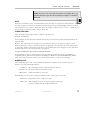
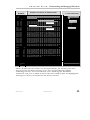
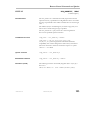
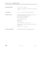
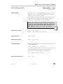
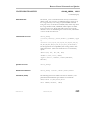
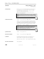
Operate Your Instrument by Remote Control
You can fully control your instrument remotely by using either the optional GPIB (General Purpose Interface
Bus) port, if available, or the LAN communication port on the scope's I/O panel, shown below (8). The only
actions for which you must use the front panel controls are to power up the scope and to set remote control
addresses.
Typ ic a l I /O p an e l , i ncl u d in g t h e LAN po rt ( 8) us ed f o r r e mot e c ont ro l
TIP: Use the instrument's Remote Control Assistant to monitor all your remote control
operations. See the COMM_HELP command in Part Two of this manual.”
STANDARDS
LeCroy’s remote control commands conform to the GPIB IEEE 488.2* standard. This may be considered an
extension of the IEEE 488.1 standard, which deals mainly with electrical and mechanical issues.
COMPATIBILITY WITH OTHER LECROY SCOPES
Throughout LeCroy's history, the company has striven to maximize compatibility. This policy continues to
operate. But the X-Stream DSOs introduce a completely new philosophy in scope communication, enabling the
scopes to control powerful proprietary programs within the instrument and within the processing chain. You
may find that a few “GPIB” commands, used for the earlier scopes, do not work on X-Stream scopes. The
solution is to use the new Automation commands, which are described in Chapter 6. It is easy to integrate these
commands into a GPIB program, using the command VBS. But you should find that for the most frequently
used commands and queries, existing scopes and X-Stream scopes are compatible, apart from a few details.
*ANSI/IEEE Std. 488.2–1987, IEEE Standard Codes, Formats, Protocols, and Common Commands. The Institute of Electrical and Electronics Engineers, Inc., 345
East 47th Street, New York, NY 10017 USA
WM-RCM-E Rev D
ISSUED: February 2005
5
PA RT O N E : A B O U T R E M OT E C O N T RO L
PROGRAM MESSAGES
You control the oscilloscope remotely using program messages that consist of one or more commands or
queries. The program messages you send from the external controller to the X-Stream oscilloscope must
conform to precise format structures. The oscilloscope will execute all program messages sent in the correct
form, but will ignore those with errors.
You can use uppercase or lowercase characters, or both, in program messages; the scope does not distinguish
between them. But the MESSAGE command can faithfully transmit strings containing both lowercase and
uppercase letters.
Warning or error messages are normally not reported unless the controller explicitly examines the relevant status
register, or if the status-enable registers have been set so that the controller can be interrupted when an error
occurs. If you connect an external monitor to the instrument’s LAN port, however, you will be able to observe
all your remote control transactions, including error messages, as they happen. See the command
COMM_HELP in Part Two, “C om ma nds.”
Program messages are separated by semicolons ; and end in a terminator:
<command/query>;.........;<command/query> <terminator>.
The oscilloscope will not decode an incoming program message before receiving its terminator. The exception is
when the program message is longer than the 256 byte input buffer; then the oscilloscope will start analyzing the
message when the buffer is full. Commands and queries are executed in the order in which they are transmitted.
In GPIB mode, the following are valid terminators:
<NL>
New Line character (i.e., the ASCII new-line character, whose decimal value is 10)
<NL><EOI>
New Line character with a simultaneous <EOI> signal
<EOI><EOI>
Signal together with the last character of the program message
The <NL> <EOI> terminator is always used in response messages sent by the oscilloscope to the controller.
NOTE: The <EOI> signal is a dedicated GPIB interface line, which can
be set with a special call to the GPIB interface driver. Refer to the GPIB
interface manufacturer’s manual and support programs.
COMMANDS AND QUERIES
Program messages are made up of one or more commands or queries. While the command directs the
oscilloscope to change its state (for example, its timebase or vertical sensitivity) the query asks the oscilloscope
about that state. Very often, you will use the same characters for a command and a query, the query being
identified by a ? after the last character.
For example, to change the timebase to 2 ms/div, send this command to the oscilloscope:
TIME_DIV 2 M
Or, to ask the oscilloscope about its timebase, send this query: TIME_DIV?
6
ISSUED: February 2005
WM-RCM-E Rev D
CHAPTER ONE:
Overview
TIP: The response to a query can be a useful
way of generating a command that is known to
be correct, and the response can be copied
straight into your program.
A query causes the oscilloscope to send a response message. The control program should read this message with
a ‘read’ instruction to the GPIB or LAN interface of the controller.
The response message to the above query might be: TIME_DIV 10 NS
The portion of the query preceding the question mark is repeated as part of the response message. If desired,
this text can be suppressed with the command: COMM_HEADER.
Depending on the state of the oscilloscope and the computation to be done, several seconds may pass before a
response is received. Command interpretation does not have priority over other oscilloscope activities.
The general form of a command or a query consists of a command header, <header>, optionally followed by
one or several parameters, <data>, separated by commas:
<header>[?] <data>,...,<data>
The notation [?] shows that the question mark is optional (turning the command into a query).
There is a space between the header and the first parameter.
Use commas between parameters.
The terminator is not shown because usually it is automatically added by the interface driver routine writing to
GPIB.
TIP: Set the controller I/O timeout conditions
to three or more seconds to give the scope time
to respond. An incorrect query will not get a
response; and, if Remote Control Assistant is
enabled, a beep will sound.
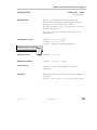
Following are examples of how program messages are made up of commands and queries.
GRID DUAL This program message consists of a single command that instructs the oscilloscope to display a
dual grid.
BUZZ BEEP; DISPLAY OFF; DATE? This program message consists of two commands, followed by a
query. They instruct the oscilloscope to beep once, turn off the display, and then ask for the current date. Again,
the terminator is not shown.
DATE 15,JAN,1993,13,21,16 This command instructs the oscilloscope to set its date and time to 15 JAN 1993,
13:21:16. The command header DATE indicates the action, the 6 data values specify it in detail.
WM-RCM-E Rev D
ISSUED: February 2005
7
PA RT O N E : A B O U T R E M OT E C O N T RO L
HEADERS
The header is the mnemonic form of the operation to be performed by the oscilloscope. Most command and
query headers have a long form, which allows them to be read more easily by people, and a short form for better
transfer and decoding speed. The two are fully equivalent and you can use them interchangeably. For example,
TRIG_MODE AUTO and TRMD AUTO are two separate but equivalent commands for switching to the
automatic trigger mode.
Some command or query mnemonics are imposed by the IEEE 488.2 standard. They are standardized so that
different oscilloscopes will present the same programming interface for similar functions. All these mnemonics
begin with an asterisk *. For example, the command *RST is the IEEE 488.2 imposed mnemonic for resetting
the oscilloscope, whereas *TST? instructs the oscilloscope to perform an internal self-test and report the
outcome.
HEADER PATHS
Certain commands or queries apply to a subsection of the oscilloscope; for example, a single input channel or a
trace on the display. In such cases, you must prefix the header by a path name that indicates the channel or trace
to which the command applies. The header path normally consists of a two-letter path name followed by a
colon : immediately preceding the command header. One of the waveform traces can usually be specified in the
header path:
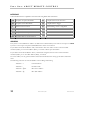
Header Path Name
Waveform Trace
C1, C2
Channels 1 and 2
C3, C4
Channels 3 and 4 (on four-channel models)
M1, M2, M3, M4
Memories 1, 2, and 3 and 4
F1, 2, F3, F4, F5, F6, F7, F8
Traces F1 through F8
TA, TB, TC, TD
Equivalent to F1 through F4, for backward
compatibility with other LeCroy DSOs.
EX, EX10, EX5
External trigger
LINE
LINE source for trigger
Example: C1:OFST -300 MV Command to set the offset of Channel 1 to -300 mV.
You need only specify a header path once. Subsequent commands with header destinations not indicated are
assumed to refer to the last defined path. For example, the queries C2:VDIV?; C2:OFST? ask: What is the vertical
sensitivity and the offset of channel 2? While the queries C2:VDIV?; OFST? ask exactly the same questions
without repeating the path.
8
ISSUED: February 2005
WM-RCM-E Rev D
CHAPTER ONE:
Overview
NOTE: If you use one of the older trace labels, for example "TC", any
response from the scope uses the new label; for example, it substitutes
F3 for TC.
DATA
Whenever a command or query uses additional data values, the values are expressed as ASCII characters. There
is a single exception: the transfer of waveforms with the command/query WAVEFORM, where the waveform
can be expressed as a sequence of binary data values. See Chapter 4, “Wavefo r m St r uc ture.” ASCII data can
have the form of character, numeric, string, or block data.
CHARACTER DATA
These are simple words or abbreviations to indicate a specific action.
Example: F3:TRA ON
In this example, the data value ON commands the trace F3 to be turned on (the data value OFF will have the
opposite effect).
However, this can become more complex. In some commands, where you can specify as many as a dozen
different parameters, or where not all the parameters are applicable at the same time, the format requires pairs
of data values. The first value names the parameter to be modified, while the second gives its value. Only those
parameter pairs that are to be changed need to be indicated.
Example: HARDCOPY_SETUP DEV,EPSON,PORT,GPIB
In this example, two pairs of parameters have been used. The first specifies the device as an EPSON (or
compatible) printer, while the second indicates the GPIB port. While the command HARDCOPY_SETUP
allows many more parameters, either they are not relevant for printers or they are left unchanged.
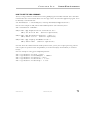
NUMERIC DATA
The numeric data type is used to enter quantitative information. Numbers can be entered as integers or
fractions, or in exponential representation:
F1:VPOS -5
C2:OFST 3.56
TDIV 5.0E-6
Move the display of Trace A downward by five divisions.
Set the DC offset of Channel 2 to 3.56 V.
Adjust the timebase to 5 µsec/div.
Example: There are many ways of setting the timebase of the oscilloscope to 5 µsec/div:
TDIV 5E-6
Exponential notation, without any suffix.
TDIV 5 US
Suffix multiplier U for 1E−6, with the (optional) suffix S for
seconds, or TDIV 5000 NS or TDIV 5000E-3 US
WM-RCM-E Rev D
ISSUED: February 2005
9
PA RT O N E : A B O U T R E M OT E C O N T RO L
You can follow numeric values with multipliers and units to modify the value of the numerical expression. The
following mnemonics are recognized:
Multiplier
Exp. Note.
Suffix
Multiplier
Exp. Note.
Suffix
EX
1E18
Exa-
PE
1E15
Peta-
T
1E12
Tera-
G
1E9
Giga-
MA
1E6
Mega-
K
1E3
kilo-
M
1E−3
milli-
U
1E−6
micro-
N
1E−9
nano-
P
1E−12
pico-
F
1E−15
femto-
A
1E−18
atto-
STRING DATA
This data type enables you to transfer a (long) string of characters as a single parameter. Simply enclose any
sequence of ASCII characters between single or double quotation marks:
MESSAGE ‘Connect probe to point J3’
The oscilloscope displays this message in the message line at the bottom of the screen.
BLOCK DATA
These are binary data values coded in hexadecimal ASCII: four-bit nibbles translated into the digits 0 through 9
or A through F, and transmitted as ASCII characters. They are used only for the transfer of waveforms from the
oscilloscope to the controller (WAVEFORM) and for instrument panel setups (PANEL_SETUP).
RESPONSE MESSAGES
The oscilloscope sends a response message to the controller in answer to a query. The format of such messages
is the same as that of program messages: individual responses in the format of commands, separated by
semicolons ; and ending in terminators. These messages can be sent back to the oscilloscope in the form in
which they were received, to be accepted as valid commands. In GPIB response messages, the <NL> <EOI>
terminator is always used.
Example: The controller sends the program message:
TIME_DIV?;TRIG_MODE NORM;C1:COUPLING? (terminator not shown).
The oscilloscope might respond to this with:
TIME_DIV 50 NS;C1:COUPLING D50 (terminator not shown).
The response message refers only to the queries: TRIG_MODE is left out. If this response is sent back to the
oscilloscope, it is a valid program message for setting its timebase to 50 ns/div and the input coupling of
Channel 1 to 50 Ω.
10
ISSUED: February 2005
WM-RCM-E Rev D
CHAPTER ONE:
Overview
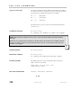
Whenever you expect a response from the oscilloscope, you must have the control program instruct the GPIB
or LAN interface to read from the oscilloscope. If the controller sends another program message without
reading the response to the previous one, the response message in the output buffer of the oscilloscope will be
discarded. The oscilloscope keeps to stricter rules for response messages than for acceptance of program
messages. While you can send program messages from the controller in uppercase or lowercase characters,
response messages are always returned in uppercase. Program messages may contain extraneous spaces or tabs
(white space), but response messages will not. And while program messages may contain a mixture of short and
long command or query headers, response messages always use short headers by default.
However, you can use the command COMM_HEADER to force the oscilloscope to use long headers, or none
at all. If the response header is omitted, the response transfer time will be minimized. But the response will not
be able to be sent back to the oscilloscope. Suffix units are also suppressed in the response. An advantage of
headerless operation is the ease with which programs can use the data, because they do not have to find and
remove the headers. But C1:PAVA? ALL will return a string like this - AMPL,292.3E-3,OK,DLY,-2.333E6,OK,FALL,95.121E-9,OK,MEAN,66E-6,OK,PER,332.8E-9,OK,PKPK,308E-3,OK,RISE,92.346E9,OK,RMS,106.1E-3,OK,SDEV,106.1E-3,OK,WID,166.3E-9,OK, even with CHDR OFF, because only the
header is removed. All other alphabetic information is always transmitted.
If you were to set the trigger slope of Channel 1 to negative, the query C1:TRSL? might yield the following
responses:
C1:TRIG_SLOPE NEG
C1:TRSL NEG
NEG
header format: long
header format: short
header format: off
TIP: Waveforms you obtain from the
oscilloscope using the query WAVEFORM?
are a special kind of response message.
Control their exact format by using the
COMM_FORMAT and COMM_ORDER
commands.
§ § §
WM-RCM-E Rev D
ISSUED: February 2005
11
C H A P T E R T W O : Control by GPIB
In this chapter, see how to
¾
Address your X-Stream scope for GPIB
¾
Configure GPIB software
¾
Enable remote and local control
¾
Make transfers of data
¾
Make service requests
¾
Poll your X-Stream scope
¾
Set timing and synchronization
12
ISSUED: February 2005
WM-RCM-E Rev D
CHAPTER
Control by GPIB
TWO
Talk, Listen, or Control
You can control your X-Stream DSO remotely, using the General Purpose Interface Bus (GPIB). GPIB is
similar to a standard computer bus. But while the computer interconnects circuit cards by means of a
backplane bus, the GPIB interconnects independent devices (oscilloscopes and computers, for example) by
means of a cable bus. GPIB also carries both program and interface messages.
Program messages, often called device dependent messages, contain programming instructions, measurement
results, oscilloscope status and waveform data.
Interface messages manage the bus itself. They perform functions such as initialization, addressing and
“unaddressing” of devices, and the setting of remote and local modes.
On the one hand, devices connected by GPIB to your X-Stream DSO can be listeners, talkers, or controllers. A
talker sends program messages to one or more listeners, while a controller manages the flow of information on
the bus by sending interface messages to the devices. The host computer must be able to play all three roles.
For details of how the controller configures the GPIB for specific functions, refer to the GPIB interface
manufacturer’s manual.
On the other hand, the X-Stream DSO can be a talker or listener, but NOT a controller.
Much of the material in this chapter is general to all GPIB systems, but where detailed instructions and
program fragments are provided in this manual, they are based on National Instruments hardware and
software, and on some form of BASIC language. Where INCLUDES are mentioned, this points to the need to
couple the programming language to the GPIB by including some drivers. The National Instruments manuals
explain this. Variables ending with % are integers, and variables ending with $ are strings, in accordance with
the practice in some BASIC languages. The entire system is of course compatible with any hardware and
software based on IEEE-488.2, and any programming language can be used if it can be linked to GPIB.
WM-RCM-E Rev D
ISSUED: February 2005
13
PA RT O N E : A B O U T R E M OT E C O N T RO L
INTERFACE
X-Stream DSO interface capabilities include the following IEEE 488.1 definitions:
AH1
Complete Acceptor Handshake
DC1
Complete Device Clear Function
SH1
Complete Source Handshake
DT1
Complete Device Trigger
L4
Partial Listener Function
PP1
Parallel Polling: remote configurable
T5
Complete Talker Function
C0
No Controller Functions
SR1
Complete Service Request Function
E2
Tri-state Drivers
RL1
Complete Remote/Local Function
ADDRESS
Every device on the GPIB has an address. To address the X-Stream DSO, set the remote control port to GPIB
by means of the scope’s front panel UTILITIES button and on-screen menus.
If you address the X-Stream DSO to talk, it will remain in that state until it receives a universal untalk
command (UNT), its own listen address (MLA), or another oscilloscope’s talk address.
If you address the X-Stream DSO to listen, it will remain configured to listen until a universal unlisten
command (UNL), or its own talker address (MTA), is received.
To avoid conflicts, use the general Unlisten and Untalk commands before setting up the talker and listener
states.
The following characters are used in GPIB to control talking and listening:
14
ASCII 63 = ?
General Unlisten
ASCII 95 = _
General Untalk
ASCII 32 = Space
Base Listen Address
ASCII 64 = @
Base Talk Address
ISSUED: February 2005
WM-RCM-E Rev D
CHAPTER TWO:
Control by GPIB
To make an actual talk address and listen address, we have to add the GPIB address to the ASCII values of the
base characters, to give the ASCII value of the new character. So a string of these commands looks like a
random set of characters. Using named variables makes programs easier to understand. For example, if we
have a DSO at GPIB address 4, and a PC at address 4, we construct the command strings as follows, for use
later in the program.
UnListen$ = Chr$ (63) : UnTalk$ = Chr$(95)
BaseListen% = 32 : BaseTalk% = 64 : DSOAddress% = 4
DSOListen$ = Chr$ (BaseListen% + DSOAddress%)
DSOTalk$ = Chr$ (BaseTalk% + DSOAddress%)
If the PC is at address 0, we can also write
PCTalk$ = Chr$ (BaseTalk%) : PCListen$ = Chr$(BaseListen%)
Finally:
DSOListenPCTalk$ = UnListen$ + UnTalk$ + PCTalk$ + DSOListen$
DSOTalkPCListen$ = UnListen$ + UnTalk$ + PCListen$ + DSOTalk$
These last two strings, once defined, can be used in programs for sending to the DSO.
GPIB SIGNALS
The GPIB system consists of 16 signal lines and eight ground or shield lines. The signal lines are divided into
three groups:
Data Lines: These eight lines, usually called DIO1 through DIO8, carry both program and interface messages.
Most of the messages use the 7-bit ASCII code, in which case DIO8 is unused.
Handshake Lines: These three lines control the transfer of message bytes between devices. The process is
called a three-wire interlocked handshake, and it guarantees that the message bytes on the data lines are sent
and received without transmission error.
Interface Management Lines: These five lines manage the flow of information across the interface:
•
ATN (ATteNtion): The controller drives the ATN line true when it uses the data lines to send
interface messages such as talk and listen addresses or a device clear (DCL) message. When ATN is
false, the bus is in data mode for the transfer of program messages from talkers to listeners.
•
IFC (InterFace Clear): The controller sets the IFC line true to initialize the bus.
•
REN (Remote ENable): The controller uses this line to place devices in remote or local program
mode.
•
SRQ (Service ReQuest): Any device can drive the SRQ line true to asynchronously request service
from the controller. This is the equivalent of a single interrupt line on a computer bus.
WM-RCM-E Rev D
ISSUED: February 2005
15
PA RT O N E : A B O U T R E M OT E C O N T RO L
•
EOI (End Or Identify): This line has two purposes: The talker uses it to mark the end of a message
string. The controller uses it to tell devices to identify their response in a parallel poll (discussed later
in this section).
I/O BUFFERS
The oscilloscope has 256-byte input and output buffers. An incoming program message is not decoded before
a message terminator has been received. However, if the input buffer becomes full (because the program
message is longer than the buffer), the oscilloscope starts analyzing the message. In this case, data transmission
is temporarily halted, and the controller may generate a timeout if the limit was set too low.
USE IEEE 488.1 STANDARD MESSAGES
The IEEE 488.1 standard specifies not only the mechanical and electrical aspects of the GPIB, but also the
low-level transfer protocol. For instance, it defines how a controller addresses devices, turns them into talkers
or listeners, resets them, or puts them in the remote state. Such interface messages are executed with the
interface management lines of the GPIB, usually with ATN true.
All these messages except GET are executed immediately upon receipt.
The command list in Part Two of this manual does not contain a command for clearing the input or output
buffers or for setting the oscilloscope to the remote state.
NOTE: In addition to the IEEE 488.1 interface
message standards, the IEEE 488.2 standard
specifies certain standardized program messages,
i.e., command headers. They are identified with a
leading asterisk * and are listed in the System
Commands section.
This is because such commands are already specified as IEEE 488.1 standard messages. Refer to the GPIB
interface manual of the host controller as well as to its support programs, which should contain special calls for
the execution of these messages.
The following description covers those IEEE 488.1 standard messages that go beyond mere reconfiguration of
the bus and that have an effect on X-Stream DSO operation.
16
ISSUED: February 2005
WM-RCM-E Rev D
CHAPTER TWO:
Control by GPIB
DEVICE CLEAR
In response to a universal Device CLear (DCL) or a Selected Device Clear message (SDC), the X-Stream DSO
clears the input or output buffers, cancels the interpretation of the current command (if any) and clears
pending commands. However, status registers and status-enable registers are not cleared. Although DCL will
have an immediate effect, it can take several seconds to execute if the oscilloscope is busy.
GROUP EXECUTE TRIGGER
The Group Execute Trigger message (GET) causes the X-Stream DSO to arm the trigger system, and is
functionally identical to the *TRG command.
REMOTE ENABLE
X-Stream DSOs do not lock out any local controls when placed in the remote state, or in RWLS. It always
accepts remote as well as local control inputs (unless you turn off remote control capability in UtilitiesÆ
Remote.)
INTERFACE CLEAR
The InterFace Clear message (IFC) initializes the GPIB but has no effect on the operation of the
X-Stream DSO.
NOTE: To illustrate the GPIB programming concepts, a number of examples are included here,
written in a similar way to BASIC. It is assumed that the controller is IBM-PC compatible, and that it
is equipped with a National Instruments GPIB interface card. Nevertheless, GPIB programming with
other languages such as C or Pascal is quite similar. If you’re using another type of computer or
GPIB interface, refer to the interface manual for installation procedures and subroutine calls.
This procedure refers to the installation and configuration of a GPIB card under the DOS operating
system. More recent operating systems (Windows 95, 98, ME, NT, 2000, XP, etc) generally use ‘Plug
‘n’ Play’ GPIB drivers, which are configured using an icon in the control panel.
CONFIGURE THE GPIB DRIVER SOFTWARE
Verify that the GPIB interface is properly installed in the computer. If it is not, follow the interface
manufacturer’s installation instructions. In the case of the National Instruments interface, it is possible to
modify the base I/O address of the board, the DMA channel number, and the interrupt line setting using
switches and jumpers. In the program examples below, default positions are assumed.
Connect the X-Stream DSO to the computer with a GPIB interface cable.
Set the GPIB address to the required value. The program examples assume a setting of 4.
WM-RCM-E Rev D
ISSUED: February 2005
17
PA RT O N E : A B O U T R E M OT E C O N T RO L
The host computer requires an interface driver that handles the transactions between the operator’s programs
and the interface board.
In the case of the National Instruments interface, the installation procedure will:
•
Copy the GPIB handler GPIB.COM into the boot directory.
•
Modify the DOS system configuration file CONFIG.SYS to declare the presence of the GPIB handler.
•
Create a sub-directory called GPIB-PC, and install in GPIB-PC a number of files and programs useful for
testing and reconfiguring the system and for writing user programs.
The following files in the sub-directory GPIB-PC are particularly useful:
IBIC.EXE allows interactive control of the GPIB by means of functions entered at the keyboard. Use of this
program is highly recommended to anyone unfamiliar with GPIB programming or with the X-Stream DSO’s
remote commands.
IBCONF.EXE is an interactive program that allows inspection or modification of the current settings of the
GPIB handler. To run IBCONF.EXE or a later program version, refer to the National Instruments manual.
NOTE: In the program examples in this section, it is assumed that the National Instruments (NI)
GPIB driver GPIB.COM is in its default state, i.e., that you have not modified it with IBCONF.EXE.
This means that the interface board can be referred to by the symbolic name ‘GPIB0’ and that devices
on the GPIB bus with addresses between 1 and 16 can be called by the symbolic names ‘DEV1’ to
‘DEV16’. If you have a National Instruments PC2 interface card rather than PC2A, you must run
IBCONF to declare the presence of this card rather than the default PC2A. Later boards from
National Instruments, and boards from other vendors, will require their own software, though NI has
achieved good compatibility with its earlier systems, and older software will often work with newer
boards.
18
ISSUED: February 2005
WM-RCM-E Rev D
CHAPTER TWO:
Control by GPIB
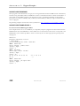
MAKE SIMPLE TRANSFERS
For a large number of remote control operations, it is sufficient to use just three different subroutines
(IBFIND, IBRD and IBWRT) provided by National Instruments. The following complete program reads the
timebase setting of the X-Stream DSO and displays it on the terminal:
GPIB:
This line holds the INCLUDE for the GPIB routines
Find:
DEV$ = “DEV4”
address 4.
‘
Because the DSO has been set at
CALL IBFIND (DEV$, SCOPE%)
‘
Find the DSO: label it “SCOPE%”.
CMD$ = “TDIV?”
‘
Make a query string about the
time base speed.
CALL IBWRT (SCOPE%, CMD$)
‘
Send the string to the DSO.
CALL IBRD (SCOPE%, RD$)
‘
Read the response from the DSO.
PRINT RD$
‘
Print the response string.
Send:
Read:
END
Explanation
GPIB: This line or lines must hold the link between the programming language and the National Instruments
GPIB functions and drivers.
Find: Open the device DEV4 and associate with it the descriptor SCOPE%. All I/O calls after that will refer
to SCOPE%. The default configuration of the GPIB handler recognizes DEV4 and associates with it a device
with the GPIB address 4.
Send: Prepare the command string TDIV? and transfer it to the oscilloscope. The command instructs the
oscilloscope to respond with the current setting of the timebase.
Read: Read the response of the oscilloscope and place it into the character string RD$.
WM-RCM-E Rev D
ISSUED: February 2005
19
PA RT O N E : A B O U T R E M OT E C O N T RO L
When running this sample program, the X-Stream DSO will automatically be set to the remote state when
IBWRT is executed, and will remain in that state. Here is a slightly modified version of the sample program
that checks if any error occurred during GPIB operation:
GPIB:
‘ This line should hold the INCLUDE for the GPIB routines
Address:
DEV$ = “DEV4”
Find:
CALL IBFIND (DEV$, SCOPE%)
Send:
CMD$ = “TDIV?”
‘
Time base query
CALL IBWRT (SCOPE%, CMD$)
ErrorS:
Read:
‘ Find the DSO.
‘ Send the string to the DSO.
IF IBSTA% < 0 THEN PRINT “WRITE ERROR =” ; IBERR% : END
CALL IBRD (SCOPE%, RD$)
DSO.
ErrorR:
‘ Try to read a string from the
IF IBSTA% < 0 THEN PRINT “READ ERROR =” ; IBERR% : END
PRINT RD$
190
END
The GPIB status word IBSTA%, the GPIB error variable IBERR% and the count variable IBCNT% are
defined by the GPIB handler and are updated with every GPIB function call. IBSTA% is negative if there is an
error, while IBERR% shows what type of error has occurred. IBCNT% is the number of bytes transferred.
Refer to the National Instruments manual for details. The sample program above would report an error if the
GPIB address of the oscilloscope was set to a value other then 4. When you are sending remote commands to
the DSO, the IBSTA% and IBERR% don’t necessarily indicate that the scope accepted the string, but merely
that the string was correctly transmitted to the DSO to interpret. To ensure that commands were valid, and
weren’t rejected by the DSO, use the Remote Control Assistant.
20
ISSUED: February 2005
WM-RCM-E Rev D
CHAPTER TWO:
Control by GPIB
USE ADDITIONAL DRIVER CALLS
IBLOC is used to execute the IEEE 488.1 standard message Go To Local (GTL); i.e., it returns the
oscilloscope to the local state. The programming example above illustrates its use.
IBCLR executes the IEEE 488.1 standard message Selected Device Clear (SDC).
IBRDF and IBWRTF, respectively, allow data to be read from GPIB to a file, and written from a file to GPIB.
Transferring data directly to or from a storage device does not limit the size of the data block, but may be
slower than transferring to the computer memory.
IBRDI and IBWRTI allow data to be read from GPIB to an integer array, and written from integer array to
GPIB. Since the integer array allows storage of up to 64 kilobytes (in BASIC), IBRDI and IBWRTI should be
used for the transfer of large data blocks to the computer memory, rather than IBRD or IBWRT, which are
limited to 256 bytes by the BASIC string length. Note that IBRDI and IBWRTI only exist for BASIC, since for
more modern programming languages, such as C, the functions called IBRD and IBWRT are far less limited in
data block size.
IBTMO can be used to change the timeout value during program execution. The default value of the GPIB
driver is 10 seconds — for example, if the oscilloscope does not respond to an IBRD call, IBRD will return
with an error after the specified time.
IBTRG executes the IEEE 488.1 standard message Group Execute Trigger (GET), which causes the X-Stream
DSO to arm the trigger system.
National Instruments supplies a number of additional function calls. In particular, it is possible to use the socalled board level calls, which allow a very detailed control of the GPIB.
NOTE: The SRQ bit is latched until the controller reads the STatus Byte Register (STB). The action
of reading the STB with the command *STB? clears the register contents except the MAV bit (bit 4)
until a new event occurs. Service requesting can be disabled by clearing the SRE register with the
*SRE 0 command.
WM-RCM-E Rev D
ISSUED: February 2005
21
PA RT O N E : A B O U T R E M OT E C O N T RO L
MAKE SERVICE REQUESTS
When an X-Stream DSO is used in a remote application, events often occur asynchronously, i.e., at times that
are unpredictable for the host computer. The most common example of this is a trigger wait after the
oscilloscope is armed: the controller must wait until the acquisition is finished before it can read the acquired
waveform. The simplest way of checking if a certain event has occurred is by either continuously or
periodically reading the status bit associated with it until the required transition is detected. Continuous status
bit polling is described in more detail below. For a complete explanation of status bits, refer to Chapter 5.
Perhaps a more efficient way of detecting events occurring in the oscilloscope is the use of the Service
ReQuest (SRQ). This GPIB interrupt line can be used to interrupt program execution in the controller. The
controller can then execute other programs while waiting for the oscilloscope. Unfortunately, not all interface
manufacturers support the programming of interrupt service routines. In particular, National Instruments
supports only the SRQ bit within the ISTA% status word. This requires you to continuously or periodically
check this word, either explicitly or with the function call IBWAIT. In the absence of real interrupt service
routines, the use of SRQ may not be very advantageous.
In the default state, after power-on, the Service ReQuest is disabled. You enable SRQ by setting the Service
Request Enable register with the command “*SRE” and by specifying which event should generate an SRQ.
The X-Stream DSO will interrupt the controller as soon as the selected event(s) occur by asserting the SRQ
interface line. If several devices are connected to the GPIB, you may be required to identify which oscilloscope
caused the interrupt by serial polling the various devices.
Example: To assert SRQ in response to “new signal acquired.” This event is tracked by the INR register,
which is reflected in the SRE register as the INB summary bit in position 0. Since bit position 0 has the value 1,
the command *SRE 1 enables the generation of SRQ whenever the INB summary bit is set.
In addition, the events of the INR register that may be summarized in the INB bit must be specified. The
event “new signal acquired” corresponds to INE bit 0 (value 1) while the event “return-to-local” is assigned to
INE bit 2 (value 4). The total sum is 1 + 4 = 5. Thus the command INE 5 is needed:
CMD$ = “INE 5 ; *SRE 1”
CALL IBWRT (SCOPE%, CMD$)
22
ISSUED: February 2005
WM-RCM-E Rev D
CHAPTER TWO:
Control by GPIB
Take Instrument Polls
You can regularly monitor state transitions within the oscilloscope by polling selected internal status registers.
There are four basic polling methods you can use to detect the occurrence of a given event: continuous, serial,
parallel, and *IST. By far the simplest of these is continuous polling. The others are appropriate only when
interrupt-service routines (servicing the SRQ line) are supported, or multiple devices on GPIB require constant
monitoring. To emphasize the differences between the methods, described below, the same example
(determining whether a new acquisition has taken place) is used in each case.
DO CONTINUOUS POLLING
A status register is continuously monitored until a transition is observed. This is the most straightforward
method for detecting state changes, but may not be practical in certain situations, especially with multiple
device configurations.
In the following example, the event “new signal acquired” is observed by continuously polling the INternal
state change Register (INR) until the corresponding bit (in this case bit 0, i.e., value 1) is non-zero, indicating
that a new waveform has been acquired. Reading INR clears this at the same time, so that there is no need for
an additional clearing action after a non-zero value has been detected. The command CHDR OFF instructs the
oscilloscope to omit any command headers when responding to a query, simplifying the decoding of the
response. The oscilloscope will then send “1” instead of “INR 1”:
CMD$ = “CHDR OFF”
CALL IBWRT (SCOPE%, CMD$)
MASK% = 1 ‘ New Signal Bit has value 1
DO
CMD$ = “INR?”
CALL IBWRT (SCOPE%, CMD$)
CALL IBRD (SCOPE%, RD$)
NEWSIG% = VAL (RD$) AND MASK%
LOOP UNTIL NEWSIG% = MASK%
WM-RCM-E Rev D
ISSUED: February 2005
23
PA RT O N E : A B O U T R E M OT E C O N T RO L
TAKE A SERIAL POLL
Serial polling takes place once the SRQ interrupt line has been asserted, and is only advantageous when you are
using several oscilloscopes at once. The controller finds which oscilloscope has generated the interrupt by
inspecting the SRQ bit in the STB register of each. Because the service request is based on an interrupt
mechanism, serial polling offers a reasonable compromise in terms of servicing speed in multiple-device
configurations.
In the following example, the command INE 1 enables the event “new signal acquired” to be reported in the
INR to the INB bit of the status byte STB. The command *SRE 1 enables the INB of the status byte to
generate an SRQ whenever it is set. The function call IBWAIT instructs the computer to wait until one of
three conditions occurs: &H8000 in the mask (MASK%) corresponds to a GPIB error, &H4000 to a timeout
error, and &H0800 to the detection of RQS (ReQuest for Service) generated by the SRQ bit.
Whenever IBWAIT detects RQS, it automatically performs a serial poll to find out which oscilloscope
generated the interrupt. It will only exit if there was a timeout or if the oscilloscope (SCOPE%) generated
SRQ. The additional function call IBRSP fetches the value of the status byte, which may be further interpreted.
For this to work properly, the value of “Disable Auto Serial Polling” must be set to “off ” in the GPIB handler
(use IBCONF.EXE to check).
CMD$ = “*CLS ; INE 1;*SRE 1”
CALL IBWRT (SCOPE%, CMD$)
MASK% = &HC800
CALL IBWAIT (SCOPE%, MASK%)
IF (IBSTA% AND &HC000) <> 0 THEN PRINT “GPIB or Timeout Error” : STOP
CALL IBRSP (SCOPE%, SPR%)
PRINT “Status Byte =.”, SPR%
Board-level function calls can deal simultaneously with several oscilloscopes attached to the same interface
board. Refer to the National Instruments manual.
NOTE: After the serial poll is completed, the RQS bit in the STB status register is cleared. Note that
the other STB register bits remain set until they are cleared by means of a “*CLS” command or the
oscilloscope is reset. If these bits are not cleared, they cannot generate another interrupt.
DO A PARALLEL POLL
Like serial polling, this is only useful when several oscilloscopes are connected. The controller simultaneously
reads the Individual STatus bit (IST) of all oscilloscopes to determine which one needs service. This method
allows up to eight different oscilloscopes to be polled at the same time.
When a parallel poll is initiated, each oscilloscope returns a status bit over one of the DIO data lines. Devices
may respond either individually, using a separate DIO line, or collectively on a single data line. Data-line
assignments are made by the controller using a Parallel Poll Configure (PPC) sequence.
24
ISSUED: February 2005
WM-RCM-E Rev D
CHAPTER TWO:
Control by GPIB
In the following example, the command INE 1 enables the event “new signal acquired” in the INR to be
reported to the INB bit of the status byte STB. The PaRallel poll Enable register (PRE) determines which
events will be summarized in the IST status bit. The command *PRE 1 enables the INB bit to set the IST bit
whenever it is itself set. Once parallel polling has been established, the parallel-poll status is examined until a
change on data bus line DIO2 takes place.
Stage 1
1.
Enable the INE and PRE registers
2.
Configure the controller for parallel poll
3.
Instruct the X-Stream DSO to respond on data line 2 (DIO2) with these commands:
CMD1$ = DSOListenPCTalk$
‘ As defined earlier
CALL IBCMD (BRD0%, CMD1$)
CMD$ = “INE 1;*PRE 1”
CALL IBWRT (BRD0%, CMD$)
PPE$ = Chr$ (&H5)
‘ GPIB Parallel Poll Enable
MSA9$ = Chr$ (&H69)
‘ GPIB Secondary Address 9
CMD4$ = PPE$ + MSA9$ + UnListen$
CALL IBCMD (BRD0%, CMD4$)
Stage 2
4.
Parallel poll the oscilloscope until DIO2 is set with these commands:
Do
CALL IBRPP (BRD0%, PPR%)
Loop Until (PPR% AND &H2) = 2
Stage 3
5.
Disable parallel polling (hex 15) and clear the parallel poll register with these commands:
PPU$ = Chr$ (&H15)
‘
GPIB Parallel Poll
Unconfigure
CALL IBCMD (BRD0%, PPU$)
CALL IBCMD (BRD0%, CMD1$)
‘
As defined earlier
CMD$ = “*PRE 0” : CALL IBWRT(BRD0%,CMD$):
In the above example, board-level GPIB function calls are used. It is assumed that the controller (board) and
the X-Stream DSO (device) are located at addresses 0 and 4, respectively.
WM-RCM-E Rev D
ISSUED: February 2005
25
PA RT O N E : A B O U T R E M OT E C O N T RO L
The listener and talker addresses for the controller and the X-Stream DSO are:
LOGIC DEVICE
LISTENER ADDRESS
TALKER ADDRESS
External Controller
32 (ASCII<space>)
64 (ASCII @)
X-Stream DSO
32 + 4 = 36 (ASCII $)
64 + 4 = 68 (ASCII D)
PERFORM AN *IST POLL
You can also read the state of the Individual STatus bit (IST) returned in parallel polling by sending the *IST?
query. To enable this poll mode, you must initialize the X-Stream DSO as for parallel polling by writing into the
PRE register. Since *IST emulates parallel polling, apply this method wherever parallel polling is not supported
by the controller. In the following example, the command INE 1 enables the event “new signal acquired” in the
INR to be reported to the INB bit of the status byte STB. The command *PRE 1 enables the INB bit to set
the IST bit whenever it is set. The command CHDR OFF suppresses the command header in the
oscilloscope’s response, simplifying the interpretation. The status of the IST bit is then continuously monitored
until set by the oscilloscope:
CMD$ = “CHDR OFF; INE 1; *PRE 1”
CALL IBWRT (SCOPE%, CMD$)
DO
CMD$
CALL
CALL
LOOP UNTIL
26
= “*IST?”
IBWRT (SCOPE%, CMD$)
IBRD (SCOPE%, RD$)
VAL (RD$) = 1
ISSUED: February 2005
WM-RCM-E Rev D
CHAPTER TWO:
Control by GPIB
Timing and Synchronization
Depending on how your remote program is written, it may be affected by timing changes between different
DSO series, even between Waverunner DSOs and WavePro DSOs. In X-Stream DSOs, these effects may be
even more pronounced than in previous scopes, for several reasons. Firstly, X-Stream DSOs are faster than our
earlier scopes. Secondly, X-Stream DSOs support faster interfaces. That is, the standard network interface is
100Base-T instead of 10Base-T. Secondly, and more significantly, for the most part our earlier scope series
processed remote commands sequentially. That is, they would not start executing any command until execution
of the previous one had finished. This meant that many operations were automatically synchronous by default,
and remote control programs which did not use status bytes or *OPC?, may have worked "by luck." That is not
the case in X-Stream DSOs. Since they use multitasking , you must be much more diligent in programming.
Most timing and synchronization problems are related to changing acquisitions, or the completion of analysis
after an acquisition occurs. For example, if you change the offset of channel 1 while the scope is in Auto
trigger mode, and then you use the PAVA? query to read a parameter computed on channel 1, in the older
scopes, you would almost always get the results after the data has been acquired with the new offset. However,
in X-Stream DSOs, the processing is overlapped with the next acquisition and, as a consequence, the PAVA?
result may have come from the acquisition prior to the offset change.
There are several ways of ensuring that your program gives the correct results when controlling the scope
remotely. To simplify the synchronization issue, in most cases you can put the scope into single trigger mode.
Then you can use either the status registers available in the scope, or the *OPC? query and the WAIT
command to detect completion when the acquisition and any processing are done.
Note that when you arm the scope by sending the TRMD SINGLE command, the scope will automatically
perform any necessary calibrations before actually starting to acquire data. These calibrations may take several
seconds, so if you query the status immediately after sending TRMD SINGLE, you need to have the GPIB (or
remote) timeout set to be at least 10 seconds to prevent a timeout before getting the correct results.
Calibrations are performed if your program changes some control settings (e.g., volts/div, number of active
channels, etc.) or if the temperature of the scope has changed significantly. You can disable the calibrations by
sending the AUTO_CALIBRATE OFF command. However, the scope performance may be degraded if the
temperature changes and it does not get a chance to self calibrate. A calibration of the X-Stream DSO can be
"forced" by issuing a *CAL? command. This technique allows you to control the timing of calibrations so that
they will not interfere with the acquisition of important data.
One case when you may need to use "normal" or "auto" trigger mode is the accumulation of many acquisitions
for functions such as averaging or histogramming. In this case, it is best to stop the acquisitions, set up the
scope, and then set the trigger mode to NORMAL to acquire the data. (A possible alternative is to use
sequence mode. It is faster, but does require that you know how many acquisitions to accumulate. That number
can be specified and captured in sequence mode).
WM-RCM-E Rev D
ISSUED: February 2005
27
PA RT O N E : A B O U T R E M OT E C O N T RO L
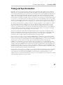
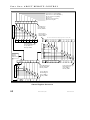
STATUS REGISTERS
Status registers store a record of events and conditions that occur inside the DSO. Some of the events
recorded are: New data has been acquired; Processing has completed; Hardcopy has completed; An error has
occurred; etc. The programmer can use the registers to sense the condition of the instrument by polling them
until the desired status bit has been set. A status register can be polled by querying its associated remote
command (e.g., *STB, INR?, *ESR, etc.). Alternatively, with GPIB, the scope can request service from the
controller by using the mask registers to select the events of interest.
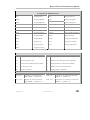
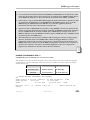
The following diagram (Figure 1) shows the steps necessary to acquire data using the status registers for
synchronization.
28
ISSUED: February 2005
WM-RCM-E Rev D
CHAPTER TWO:
Control by GPIB
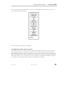
If the data have already been acquired and you want to do further analysis (math, parameters, cursors) on it,
you can proceed as shown in Figure 2:
For more details on Status registers, see Chapter 5.
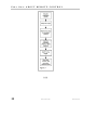
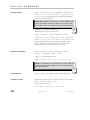
SYNCHRONZING WITH *OPC? AND WAIT
The *OPC? query returns a 1 when the previous commands have finished. Therefore, you can use this query
with the WAIT command to synchronize the scope with your controller, using the steps shown in Figure 3
below. The WAIT command waits for the acquisition to complete, but it does not wait for the processing. The
WAIT command allows you to specify an optional timeout so that if the scope does not trigger, your program
will not hang. However, if you use the timeout, it is strongly advised to subsequently check the status registers
to ensure that the scope actually triggered and that any processing has completed.
WM-RCM-E Rev D
ISSUED: February 2005
29
PA RT O N E : A B O U T R E M OT E C O N T RO L
§§§
30
ISSUED: February 2005
WM-RCM-E Rev D
CHAPTER TWO:
Control by GPIB
BLANK PAGE
WM-RCM-E Rev D
ISSUED: February 2005
31
C H A P T E R T H R E E : Control by LAN
In this chapter, see how to
¾
Control X-Stream by LAN
¾
Simulate GPIB messages using LAN
32
ISSUED: February 2005
WM-RCM-E Rev D
CHAPTER
Control by LAN
THREE
Introduction
¾
The Ethernet connection (10Base-T and 100Base-T) allows you to control the instrument over a network,
or through a direct connection between the oscilloscope and a computer. The connection is made through
the Ethernet port located at the rear of the oscilloscope.
¾
This chapter introduces the basic capabilities for control of the instrument over the Ethernet interface.
This manual gives a complete description of the remote control commands. The commands apply to control
of the oscilloscope via Ethernet and GPIB.
Implementation Standard
To the greatest extent possible, these remote commands conform to the IEEE 488.21 standard, which may be
considered an extension of the IEEE 488.1 standard, dealing mainly with electrical and mechanical issues.
When using LAN, the strings of data that are to be sent to the instrument must be preceded by the requisite
header.
Connections
The oscilloscope can be connected to the computer via Ethernet, using a TCP/IP network protocol.
This connection can be made through a network (using a hub, switch, etc,) with a straight through network
cable, or between the oscilloscope’s Ethernet interface and a computer using a crossover network cable.
Connecting the Instrument to its Host
This section describes connecting the instrument to the host PC or network over the standard
10Base-T/100Base-T Ethernet. Windows NT and Windows 95 operating systems are supported.
1 ANSI/IEEE Std. 488.2–1987, IEEE Standard Codes, Formats, Protocols, and Common Commands. The Institute of Electrical and
Electronics Engineers Inc., 345 East 47th Street, New York, NY 10017, USA.
WM-RCM-E Rev D
ISSUED: February 2005
33
PA RT O N E : A B O U T R E M OT E C O N T RO L
Scope Rear Panel
The LAN connector is shown in the illustration above (item 8).
•
Supports IEEE 802.3 Ethernet standards
•
Supports 10Base-T and 100Base-T
Ethernet Connection
The instrument operates over a standard 10Base-T/100Base-T Ethernet connection. The instrument can be
plugged into a network or operated from a direct connection to a host computer. A different type of cable is
required for each of these connections. For a direct connection to the PC, a crossover cable is required,
whereas the network connection is made using a straight cable.
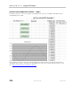
Headers for LAN Data Transfers
The format of the header sent before each data block, both to and from the instrument, is set out in the
following table:
Purpose
Byte #
0
Operation
1
Header Version
2
Sequence Number*
3
Spare (reserved for future expansion)
4
Block Length, (bytes of data), LSB
5
Block Length (bytes of data)
6
Block Length (bytes of data)
7
Block Length, (bytes of data), MSB
* The sequence number is used to synchronize write/read operations to simulate 488.2
“discard unread response” behavior. Valid range is 1 to 255 (zero is omitted
intentionally).
34
ISSUED: February 2005
WM-RCM-E Rev D
C H A P T E R T H R E E : Control by LAN
The ‘Operation’ bits and meanings are:
D7
D6
D5
D4
D3
D2
D1
D0
DATA
REMOTE
LOCKOUT
CLEAR
SRQ
SERIAL
POLL
Reserved
EOI
DATA
BIT
MNEMONIC
PURPOSE
D7
DATA
Data block (D0 indicates termination with/without EOI)
D6
REMOTE
Remote Mode
D5
LOCKOUT
Local Lockout (Lock out front panel)
D4
CLEAR
Device Clear (if sent with data, clear occurs before data block is passed to parser)
D3
SRQ
SRQ (Device to PC only)
D2
SERIALPOLL
Request a serial poll
D1
Reserved
Reserved for future expansion
D0
EOI
Block terminated in EOI
Logic "1" = use → EOI terminator
Logic "0" = no EOI terminator
Note: The following examples assume that the host PC operates from Windows™ 95. The
connection procedure for Windows NT is similar.
WM-RCM-E Rev D
ISSUED: February 2005
35
PA RT O N E : A B O U T R E M OT E C O N T RO L
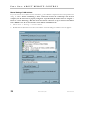
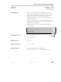
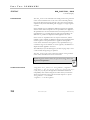
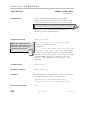
Manual Setting of LAN Address
If you do need to set an address for the instrument, go into Windows and perform the usual operations for
setting an address. Before establishing a direct connection between the oscilloscope and the host
computer, the PC must first be properly configured. A specific TCP/IP address must be assigned —
known as "static addressing." But this means that the PC cannot be set up to obtain its IP address
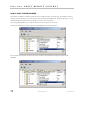
from a DHCP server. To set the host PC’s static address with Windows 95:
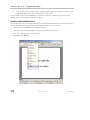
1.
S e le c t Sta r t → Set t in gs → C o ntr o l Pane l.
2.
Double-click the Network icon in the Control Panel. A network dialog box similar to this one appears:
36
ISSUED: February 2005
WM-RCM-E Rev D
C H A P T E R T H R E E : Control by LAN
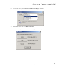
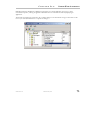
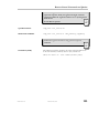
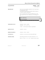
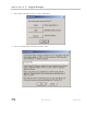
3.
If the TCP/IP protocol is not listed, you will have to add it. Follow your operating system user guide to
add the TCP/IP protocol and bind it to the Ethernet adapter.
4.
Double-click the
5.
If this has already been selected, the computer’s static address is set and nothing more needs to be done.
Cancel out of the TCP/IP and network dialog boxes, and close the control panel.
6.
If the address has not already been selected, fill in the IP address and subnet mask as shown above. The
subnet mask for 172.25.x.x is 255.255.0.0. If the computer will not be plugged into a network, the above
WM-RCM-E Rev D
line. A dialog box similar to the one below appears. Select
ISSUED: February 2005
37
PA RT O N E : A B O U T R E M OT E C O N T RO L
address (or almost any address within the chosen subnet) will suffice. The only address that will not work
is the same one as that of the oscilloscope to be controlled.
7.
Now click
in the TCP/IP Properties dialog box. Depending on the operating system and
version, you may need to reboot the computer. If so, a dialog box should alert you to this.
Making Physical Connection
To make the physical connection between the oscilloscope and the host computer:
1.
Connect the oscilloscope to the PC using a crossover cable (for direct connection).
2.
Power the oscilloscope unit on.
Note: If your PC does not have TCIP/IP, see your computer’s User’s Manual for installation
instructions.
Note: If you are making connection using the VCIP protocol, use this syntax:
VICP::<scope’s IP address>
For example, VICP::172.28.15.16
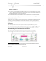
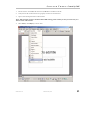
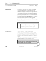
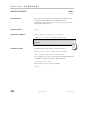
Verifying Connection
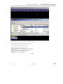
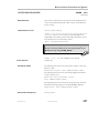
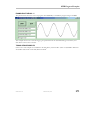
The physical connection and the PC’s TCP/IP configuration can be verified using the “ping” command,
available on both Windows™ 95 and Windows™ NT with TCP/IP network protocol installed. In order to
check the network connection between the PC and the oscilloscope:
1.
Start MS-DOS Prompt
2.
Type ping <ip_address>, where <ip_address> is the static address assigned to the oscilloscope. The
Command Prompt window on the next page illustrates the result of a successful “ping,” with the Ethernet
connection shown established. The ping command has sent a message to the instrument and waited
for a response. If a timeout occurs, the IP address used for the destination (the oscilloscope) is
incorrect or not within the subnet mask of the PC’s IP.
38
ISSUED: February 2005
WM-RCM-E Rev D
C H A P T E R T H R E E : Control by LAN
Network Connection
Check with your network administrator before connecting the oscilloscope to a network. Incorrect addresses
on a network can cause both the network and the oscilloscope to behave strangely. However, a network
connection ought to be as simple as plugging the oscilloscope into the network. Proper connection can be verified by
following the verification instructions in the previous section.
If you are concerned mainly with system throughput, network connection is not recommended
because the network traffic will slow down the oscilloscope’s data transfer rate.
Note: The default Gateway is assigned as "172.25.0.1". Unless your network has this Gateway
available, you must ensure that the computer and the oscilloscope are on the same subnet.
Changing IP Address Once the IP address is changed, the unit will no longer respond to the original address.
If the network settings are unknown or accidentally set to invalid values, they can be recovered by following the
procedure above.
WM-RCM-E Rev D
ISSUED: February 2005
39
PA RT O N E : A B O U T R E M OT E C O N T RO L
Introduction to Software Tools
The instrument software tools allow you to develop your own application specific programs quickly
and easily. These tools are based on ActiveDSO™. The files for all the software described here are to
be found on the CD-ROM and on LeCroy’s Web site at http://www.lecroy.com/tm/library/software/.
ActiveDSO Based on Microsoft’s ActiveX control technology, ActiveDSO gives leverage to widely available
Microsoft software tools, and makes programming within the Microsoft environment easier. ActiveDSO
simplifies the computer’s interface with the instrument, and simplifies programming within Visual C++, Visual
Basic, or any other ActiveX compatible applications. For example, Microsoft Excel can even be used to control
and retrieve data directly from the instrument. This tool becomes part of the target application and provides
seamless access to the full power of the instrument.
Using ActiveDSO
ActiveDSO is highly suitable for fast program development in the Microsoft environment. This
program is a control of ActiveX, the software technology developed by Microsoft as a subset of its
COM model.
ActiveDSO facilitates programming with the instrument by providing a ready interface between the instrument
and the host computer. Programs such as Visual C++, Visual Basic, or Visual Basic for Applications (VBA) can
be used under remote control without concern for interfacing complications. ActiveDSO acts as the key design
structure allowing effective integration of software from the different manufacturers supporting ActiveX
containment.
CONTROL INSTANTIATION
This ActiveX component can be instantiated more than once by using the Visual Basic function CreateObject.
Once the object is created, invoking the connection method will initialize it. ActiveDSO enables control of the
instrument from a variety of PC desktop applications. The complexities of programming with Ethernet are
fully encapsulated in this control. For example, with less than 10 lines of VBA code in an Excel macro the
spreadsheet can recover pre-scaled waveform data from the X-Stream DSO (see the on-line Excel example in
ActiveDSO).
ActiveDSO control can be used in two fundamental ways:
1.
As a visible object embedded in an OLE automation compatible client (PowerPoint, for example) showing
a captured instrument display image. See the Embedded Control example below for more details.
2.
As an invisible object accessed through a scripting language (VBA, for example) to remotely control the
instrument. See VBA example below for more details.
The ActiveDSO control may be embedded in any ActiveX containment-capable client, and may be used
manually without need of any programming or scripting.
Example: PowerPoint This example shows the control being embedded in a Microsoft PowerPoint slide. The
waveform captured by the instrument can be easily imported into PowerPoint with just a few mouse clicks:
40
ISSUED: February 2005
WM-RCM-E Rev D
C H A P T E R T H R E E : Control by LAN
1.
Ensure that the ActiveDSO files from the CD-ROM are installed on the PC.
2.
Verify that the PC and instrument are properly connected to the Ethernet.
3.
Open a new blank presentation in PowerPoint.
Note: This example assumes that PowerPoint 2002 is being used. Earlier (or Later) versions may not
behave in the same manner.
4.
Select Insert, then Object, as shown here:
WM-RCM-E Rev D
ISSUED: February 2005
41
PA RT O N E : A B O U T R E M OT E C O N T RO L
5.
42
From the pop-up window, select LeCroy ActiveDSO Control, as shown here:
ISSUED: February 2005
WM-RCM-E Rev D
C H A P T E R T H R E E : Control by LAN
6.
From the Edit menu, select LeCroy ActiveDSO Control Object, then Edit::
7.
Right-click the object and select Make Connection.
8.
Select Network TCP/IP connection, as shown here (“scope” = WaveMaster):
WM-RCM-E Rev D
ISSUED: February 2005
43
PA RT O N E : A B O U T R E M OT E C O N T RO L
9.
Enter the instrument’s IP address and click OK.
The address can also be specified in URL form, or 127.0.0.1 if you are running the controlling application
on the instrument.
44
ISSUED: February 2005
WM-RCM-E Rev D
C H A P T E R T H R E E : Control by LAN
10. Right-click the object again and select the Refresh Image menu item. A captured waveform will be
displayed similar to the one shown here:
Instrument’s captured waveform imported into PowerPoint
Once the ActiveDSO object has been properly set within the application, a macro script can be created,
utilizing an object method such as WriteString() to send DISP ON, C1:TRA ON, TRMD. Then RefreshImage()
method can be used to update the screen.
WM-RCM-E Rev D
ISSUED: February 2005
45
PA RT O N E : A B O U T R E M OT E C O N T RO L
Example:
VBA
VBA is the programming language built in to many of the more recent Windows applications. It is a subset of
Visual Basic that makes using OLE Automation Servers and ActiveX Controls very simple. The following VBA
subroutine demonstrates how easy it is to connect to an instrument and send remote commands to it.
_______________________________________________________
Sub LeCroyDSOTest()
Dim dso As Object
Set dso = CreateObject("LeCroy.ActiveDSO.1")
Call dso.AboutBox
‘ Present the control's About box
Call dso.MakeConnection("IP:172.25.1.2")
‘ Connect to the unit
Call dso.WriteString("C1:VDIV 2", 1)
‘ Setup C1 for 2 Volts/Div
Call dso.WriteString("TRMD AUTO", 1)
‘ Set the trigger mode to AUTO
End Sub
_____________________________________________________
To enter the VBA editor in members of the Microsoft Office suite:
1.
Select Tools → Macro → Visual Basic Editor menu item.
2.
When the VBA window appears, select the Insert → Module menu item.
3.
Copy the above example into the editor window that appears.
To execute:
4.
Position the text cursor within the subroutine.
5.
Either select the Run → Run Sub/UserForm or press function key F5.
Note: For more information, see the ActiveDSO on-line Help. On-line Help contains VisualC++
examples, and explanations of ActiveDSO Methods and Properties.
ActiveDSO This ActiveXTM control enables LeCroy oscilloscopes to be controlled by, and to exchange
data with, a variety of Windows applications that support the ActiveX standard. MS Office programs, Internet
Explorer, Visual Basic, Visual C++, Visual Java, and MATLAB (V5.3 and later) are a few of the many
applications that support ActiveX controls. ActiveDSO is available on CD-ROM or on the internet at
www.lecroy.com
•
With ActiveDSO you can develop your test program using standard GPIB commands. For easy integration
of your scope data with your Windows Application (through GPIB or Ethernet 10Base-T or 100Base-T),
ActiveDSO helps you with the following tasks:
•
Generate a report by importing scope data right into Excel or Word.
46
ISSUED: February 2005
WM-RCM-E Rev D
C H A P T E R T H R E E : Control by LAN
•
Archive measurement results on the fly in a Microsoft Access Database.
•
Automate tests using Visual Basic, Java, C++, Excel (VBA).
•
The ActiveDSO control hides the intricacies of programming and provides a simple and consistent
interface to the controlling application. With less than 10 lines of VBA (Visual Basic for Applications)
code in an Excel macro the spreadsheet can recover pre-scaled waveform data from a remote instrument.
•
The ActiveDSO control can also be embedded visually in any OLE automation compatible client, and can
be used manually without any need for programming. It will run on any PC running Windows 95,
Windows 98, or Windows NT.
•
There are two fundamental ways to use the control:
o
As a visible object embedded in an OLE Automation compatible Client (PowerPoint for example)
showing a captured display image. See Embedded Control Example for more details.
o
As an invisible object accessed via a scripting language (Visual Basic for Applications, for example) to
remotely control an instrument. See Accessing from VBA for more details.
•
VBA (Visual Basic for Applications) is the programming language built into many of the more recent
Windows applications. It is a subset of Visual Basic that makes it very simple to utilize the services of
OLE Automation Servers and ActiveX Controls.
•
The following VBA subroutine demonstrates how easy it is to connect to an instrument and send remote
commands to it.
Sub LeCroyDSOTest()
Dim o As Object
Set o = CreateObject("LeCroy.ActiveDSOCtrl.1")
Call o.AboutBox
' Present the control's About box
Call o.MakeConnection("IP: 172.28.11.26)
Call o.WriteString("BUZZ BEEP", True)
'Connect to device on LAN
' Make the DSO beep
End Sub
Example Syntax:
•
Boolean controlName.WriteString
•
The WriteString method has the following arguments.
Argument Description
•
controlnameThe name of the ActiveDSO control object.
•
textString String, Text string to send to the device.
•
EOI Boolean, TRUE = terminate with EOI
WM-RCM-E Rev D
ISSUED: February 2005
47
PA RT O N E : A B O U T R E M OT E C O N T RO L
•
Returns: True on success, False on failure.
•
Remarks: This method sends a string command to the instrument.
•
If EOI is set to TRUE, the device will start to interpret the command immediately. This is normally the
desired behavior.
•
If EOI is set to FALSE, a command may be sent in several parts with the device starting to interpret the
command only when it receives the final part, which should have EOI set to TRUE.
§§§
48
ISSUED: February 2005
WM-RCM-E Rev D
C H A P T E R T H R E E : Control by LAN
BLANK PAGE
WM-RCM-E Rev D
ISSUED: February 2005
49
C H A P T E R F O U R : Understanding and Managing Waveforms
In this chapter, see how to
¾
Structure Waveforms
¾
Inspect waveform contents
¾
Transfer waveforms rapidly
50
ISSUED: February 2005
WM-RCM-E Rev D
CHAPTER
FOUR
Understanding and Managing Waveforms
Know Your Waveform
A waveform can be said to have two main parts. One is its basic data array: raw data values from the
oscilloscope’s ADCs (Analog-to-Digital Converters) obtained in the waveform’s capture. The other is the
description that accompanies this raw data: the vertical and horizontal scale or time of day, for example,
necessary for a full understanding of the information contained in the waveform. When these parts are
transmitted together, the descriptor comes first.
You can access this descriptive information by remote control using the INSPECT? query, which interprets it
in an easily understood ASCII text form. And you can rapidly transfer the waveform data using the
WAVEFORM? query. You can write it back into the oscilloscope with the WAVEFORM command.
Your instrument contains a data structure (template, see Appendix II) that provides a detailed description of
how waveform information is organized. Although a sample template is provided with this manual, we suggest
you use the TEMPLATE? query to access the instrument template in the oscilloscope itself (the template may
change as your oscilloscope’s firmware is enhanced).
Using the STORE and STORE_SETUP commands, you can also store waveforms in preformatted ASCII
output for popular spreadsheet and math processing packages.
LOGICAL DATA BLOCKS
Each of your waveforms will normally contain at least a waveform descriptor and data array block. However,
other blocks may also be present in more complex waveforms.
Waveform Descriptor block (WAVEDESC): This includes all the information necessary to reconstitute the
display of the waveform from the data, including: hardware settings at the time of acquisition, the exact time
of the event, kinds of processing performed, your oscilloscope name and serial number, the encoding format
used for the data blocks, and miscellaneous constants.
Sequence Acquisition Times block (TRIGTIME): This is needed for sequence mode acquisitions to
record the exact timing information for each segment. It contains the time of each trigger relative to the trigger
of the first segment, as well as the time of the first data point of each segment relative to its trigger.
Random Interleaved Sampling times block (RISTIME): This is required for RIS acquisitions to record the
exact timing information for each segment.
First Data Array block (SIMPLE or DATA_ARRAY_1): This is the basic integer data of the waveform. It
can be raw or corrected ADC data or the integer result of waveform processing.
WM-RCM-E Rev D
ISSUED: February 2005
51
PA RT O N E : A B O U T R E M OT E C O N T RO L
Second Data Array block (DATA_ARRAY_2): This is a second data array, needed to hold the results of
processing functions such as Extrema or FFT math functions:
EXTREMA
FFT
DATA_ARRAY_1
Roof trace
Real part
DATA_ARRAY_2
Floor trace
Imaginary part
NOTE: The instrument template
also describes an array named DUAL.
But this is simply a way to allow the
INSPECT? command to examine the
two data arrays together.
INSPECT WAVEFORM CONTENTS
Use the INSPECT? query to examine the contents of your waveform. You can use it on both of the main
waveform parts. Its most basic form is: INSPECT? “name”, the template giving you the name of a descriptor
item or data block. You may use single quotation marks or double ones in the command (or none at all) but the
reply will always use double quotes. The answer is returned as a single string, but may cover many lines. Some
typical dialogue follows:
Question
Response
C1:INSPECT? “VERTICAL_OFFSET”
“VERTICAL_OFFSET: -4.0000e-002”
Question
Response
C1:INSPECT? “TRIGGER_TIME”
“TRIGGER_TIME: Date = APR 8, 2004, Time = 10:29: 0.311462573”
You can also use INSPECT? to provide a readable translation of the full waveform descriptor block using
INSPECT? “WAVEDESC”. Again, the template will give you the details for interpretation of each of the
parameters. Also use INSPECT? “SIMPLE” to examine the measured data values of a waveform. For example,
for an acquisition with 52 points:
INSPECT? “SIMPLE”
C1:INSP “
0.0005225 0.0006475 -0.00029
0.0001475 -0.0013525 -0.00204
-0.000915 -0.00179
-0.0002275
-0.00179
-0.0002275
0.00071
0.0002725 0.0007725
0.00071
0.0005225 0.00046
-0.00104
0.001335 -0.0009775 -0.001915
-0.000665 -0.001665
-0.0001025
-0.000915 8.50001E-05 0.000835
“
-0.000915
2.25001E-05 0.000835
-4E-05
0.0011475
0.0011475
0.0011475
0.001085
-0.00079
0.00096
-0.0003525 -0.00104
-0.0003525 -0.00129
-0.0002275
-0.00154
0.0005225
0.0012725
-0.000165
0.0012725
0.00096
0.0010225
0.00096
-0.0003525
0.0005225
The numbers in the table above are the fully converted measurements in volts. When the data block contains
thousands of items the string will contain a great many lines.
Depending on the application, you may prefer the data in its raw form, with either a BYTE (8 bits) or a
WORD (16 bits) for each data value. In that case, use the relations INSPECT? “SIMPLE”,BYTE with
52
ISSUED: February 2005
WM-RCM-E Rev D
C H A P T E R F O U R : Understanding and Managing Waveforms
WAVEFORM?. The examination of data values for waveforms with two data arrays can be performed as
follows:
INSPECT? “DUAL”
INSPECT? “DATA_ARRAY_1”
INSPECT? “DATA_ARRAY_2”
to get pairs of data values on a single line
to get the values of the first data array
to get the values of the second data array
INSPECT? has its limitations; it is useful, but also wordy. INSPECT? cannot be used to send a waveform back
to the oscilloscope. If you want to do this, or you want the information quickly, you should instead use
WAVEFORM. With WAVEFORM_SETUP it is possible to examine just a part of the waveform or a sparsed
form of it. See the following pages.
If you’re a BASIC user you might also find it convenient to use INSPECT? and WAVEFORM? together to
construct files containing a version of the waveform descriptor that both you and BASIC can read. Using a
stored waveform, this can be done in a format suitable for retransfer to the instrument with MC:INSPECT?
“WAVEDESC”;WAVEFORM?, and then placing the response directly into a disk file.
WM-RCM-E Rev D
ISSUED: February 2005
53
PA RT O N E : A B O U T R E M OT E C O N T RO L
USE THE WAVEFORM QUERY
Use the WAVEFORM? query to transfer waveform data in block formats defined by the IEEE 488.2 standard.
You can then download the response back to your instrument by using the WAVEFORM command. All your
waveform’s logical blocks can be read with the query C1:WAVEFORM? Completeness, as well as good use of
time and space are the advantages of this approach when you have to read many waveforms with the same
acquisition conditions, or when you are interested only in large amounts of raw integer data. Moreover, you can
choose any single block for reading with a query such as C1:WAVEFORM? DAT1. See Part Two for the
various block names.
You can place the binary response to a query of the form C1:WAVEFORM? or C1:WAVEFORM? ALL in a
disk file, then dump it using the GPIB bus. Do this with default settings to show the hexadecimal and ASCII
form, as on the following page.
NOTE: A waveform query response can easily be
a block containing over 16 million bytes if it is in
binary format, and twice as much if the HEX
option is used.
54
ISSUED: February 2005
WM-RCM-E Rev D
C H A P T E R F O U R : Understanding and Managing Waveforms
BYTE OFFSET
NUMBER
0
16
32
48
64
80
96
112
128
144
160
176
192
208
224
240
256
272
288
304
320
336
352
BINARY CONTENTS
IN
A SC II T R A N S L A T I O N
(.... = UNINTERESTING)
HEX ADECIMAL
43 31 3A 57 46 20 41 4C 4C 2C 23 39 30 30 30 30
30 30 34 35 30
0
11
27
43
59
75
91
107
123
139
155
171
187
203
219
235
251
267
283
299
315
331
367
368
384
400
416
432
448
464
0
1
17
33
49
65
81
97
471
00
00
00
00
00
00
00
32
01
00
00
BB
00
00
00
00
00
00
00
00
00
00
00
00
00
4C
37
00
00
00
34
00
BE
00
00
00
00
00
00
00
00
00
00
00
00
00
45
84
00
00
00
83
08
6A
00
00
00
00
00
00
00
00
0A
00
00
00
00
43
09
00
00
00
12
00
D7
00
00
00
00
00
00
00
00
00
00
00
00
68
52
40
00
00
00
6F
01
F2
00
00
00
00
00
00
00
00
00
57
4C
00
00
00
4F
00
00
00
00
3A
32
A0
00
00
00
00
00
00
17
00
3F
41
45
01
00
00
59
00
00
00
00
0D
2B
00
00
00
00
00
00
00
0A
00
80
56
43
00
00
00
39
00
00
00
00
8E
CC
00
00
00
00
00
00
00
05
00
00
45
52
00
00
00
33
00
34
33
01
C9
77
00
00
00
00
00
00
00
02
01
00
44
4F
00
00
00
37
00
00
00
00
46
BE
56
00
00
53
00
00
00
07
00
3A
45
59
00
00
00
34
00
00
00
00
FE
6B
00
00
00
00
00
00
00
C8
0E
0D
53
5F
01
00
00
4C
00
00
00
00
00
A4
00
00
00
00
00
00
00
00
00
8E
43
32
5A
00
00
00
00
34
00
01
00
BB
00
00
00
00
00
00
00
00
04
C9
00
5F
00
00
00
00
00
00
00
00
C7
51
00
00
00
00
00
00
40
00
3F
00
00
32
00
00
00
00
00
00
00
00
00
A0
00
00
00
00
00
00
3B
00
80
00
00
00
00
00
00
00
00
13
08
FC
15
F0
18
0A
00
00
00
00
00
00
00
04
1B
EC
14
11
FE
16
00
00
00
00
00
00
00
FA
1B
05
03
1D
EE
11
00
00
00
00
00
00
00
09
FA
14
F4
1E
07
00
00
00
00
00
00
16
EC
18
05
F9
19
00
00
00
00
00
00
0B
05
03
11
EA
18
00
00
00
00
00
00
F3
1B
F8
10
06
03
00
00
00
00
00
00
00
00
00
00
00
00
00
00
00
00
00
69
00
00
00
00
00
00
00
00
00
C1:WFALL,#900000
0450
WAVEDESC...
.....LECROY_2_2.
................
................
................
.LECROYLT344....
11
E8
1A
0D
F8
1D
FA
0A
(Termina
tor)
Above: To illustrate the contents of the logical blocks, the r elevant par ts have
been separated. To make counting easier, the cor r esponding Byte Of fset
numbering has been restar ted each time a new block begins. T he ASCII
translation, onl y par t of which is shown, has been similar l y split and highlighted,
showing how its par ts cor r espond to the binar y contents.
WM-RCM-E Rev D
ISSUED: February 2005
55
PA RT O N E : A B O U T R E M OT E C O N T RO L
On the previous page...
The first 10 bytes translate into ASCII and resemble the simple beginning of a query response. These are
followed by the string #9000000450, the beginning of a binary block in which nine ASCII integers are used to
give the length of the block (450 bytes). The waveform itself starts immediately after this, at Byte 21. The very
first byte is at zero byte count, as it is for the first byte in each block.
The first object is a DESCRIPTOR_NAME, a string of 16 characters with the value WAVEDESC.
Then, 16 bytes after the beginning of the descriptor, at Byte 37, we find the beginning of the next string: the
TEMPLATE_NAME with the value LECROY_2_2.
Several other parameters follow. The INSTRUMENT_NAME, LECROYLT344, 76 bytes from the descriptor
start (Byte 97), is easily recognizable.
A very important byte is found at position 34 after the descriptor start. This is the value COMM_ORDER,
which gives the order of subsequent bytes in the file. This byte is of enum type, taking the possible values 0 for
high byte first, and 1 for low byte first. All subsequent readings of the file must use the information given by
this byte.
On the preceding line, 36 bytes after the descriptor start (Byte 57), a four-byte integer gives the length of the
descriptor: WAVE_DESCRIPTOR = 00 00 01 5A (hex) = 346.
At 60 bytes from the descriptor start (Byte 81) we find another four-byte integer giving the length of the data
array: WAVE_ARRAY_1 = 00 00 00 68 (hex) = 104.
And at 116 bytes after the descriptor (Byte 137), yet another four-byte integer gives the number of data points:
WAVE_ARRAY_COUNT = 00 0000 34 (hex) = 52.
Now we know that the data will start at 346 bytes from the descriptor’s beginning (Byte 367), and that each of
the 52 data points will be represented by two bytes. The waveform has a total length of 346 + 104, which is the
same as the ASCII string indicated at the beginning of the block. The final 0A at Byte 471 is the NL character
associated with the GPIB message terminator <NL><EOI>.
Because the example was taken using an oscilloscope with an eight-bit ADC, we see the eight bits followed by a
0 byte for each data point. However, for many other kinds of waveform this second byte will not be zero and
will contain significant information. The data is coded in signed form (two’s complement) with values ranging
from -32768 = 8000 (hex) to 32767 = 7FFF (hex). If we had chosen to use the BYTE option for the data
format, the values would have been signed integers in the range -128 = 80 (hex) to 127 = 7F (hex). The ADC
values are mapped to the display grid in the following way:
•
0 is located on the grid’s center axis
•
127 (BYTE format) or 32767 (WORD format) is located at the top of the grid
•
-128 (BYTE format) or -32768 (WORD format) is located at the bottom of the grid.
From bottom to top of the screen we have 80 , 81, 82 . . . . FD, FE, FF, 0, 1, 2 . . . . 7D, 7E, 7F.
To convert from these byte values to actual numerical values, or vice versa, we can use the following formula,
for eight bit values: - New value = [Old value + 80 (hex) ] AND 255.
56
ISSUED: February 2005
WM-RCM-E Rev D
C H A P T E R F O U R : Understanding and Managing Waveforms
INTERPRET VERTICAL DATA
Knowing now how to decipher the data, you may wish to convert it to the appropriate measured values. The
vertical reading for each data point depends on the vertical gain and the vertical offset given in the descriptor.
For acquisition waveforms, this corresponds to the volts/div and voltage offset selected after conversion for
the data representation being used. The template tells us that the vertical gain and offset can be found at Bytes
156 and 160 and that they are stored as floating point numbers in the IEEE 32-bit format. An ASCII string
giving the vertical unit is to be found in VERTUNIT, Byte 196. The vertical value is given by the relationship:
value = VERTICAL_GAIN x data - VERTICAL_OFFSET, where:
VERTICAL_GAIN
2.44141e-07 from the floating point number 3483 126f at Byte 156
VERTICAL_OFFSET
0.00054 from the floating point number 3A0D 8EC9 at Byte 160
VERTICAL_UNIT
V = volts from the string 5600 ... at Byte 196
Therefore:
since data[4] =
value[4] =
FA00 = 64000 from the hexadecimal word FA00 at byte 373. Overflows the maximum. 16
bit value of 32767, so must be a negative value. Using the two’s complement conversion
64000-216 = -1536
-0.000915 V as stated in the inspect command
If the computer or the software available is not able to understand the IEEE floating point values, use the
description in the template.
The data values in a waveform may not all correspond to measured points. FIRST_VALID_PNT and
LAST_VALID_PNT give the necessary information. The descriptor also records the SPARSING_FACTOR,
the FIRST_POINT, and the SEGMENT_INDEX to aid interpretation if the options of the
WAVEFORM_SETUP command have been used.
For sequence acquisitions, the data values for each segment are given in their normal order and the segments
are read out one after the other. The important descriptor parameters are the WAVE_ARRAY_COUNT and
the SUBARRAY_COUNT, giving the total number of points and the number of segments.
For waveforms such as the extrema and the complex FFT there will be two arrays (one after the other) for the
two of the result.
WM-RCM-E Rev D
ISSUED: February 2005
57
PA RT O N E : A B O U T R E M OT E C O N T RO L
CALCULATE A DATA POINT’S HORIZONTAL POSITION
Each vertical data value has a corresponding horizontal position, usually measured in time or frequency units.
The calculation of this position depends on the type of waveform. Each data value has a position, i, in the
original waveform, with i = 0 corresponding to the first data point acquired. The descriptor parameter
HORUNIT gives a string with the name of the horizontal unit.
Single Sweep waveforms: x[i] = HORIZ_INTERVAL x i + HORIZ_OFFSET. For acquisition waveforms
this time is from the trigger to the data point in question. It will be different from acquisition to acquisition
since the HORIZ_OFFSET is measured for each trigger. In the case of the data shown above this means:
HORIZ_INTERVAL =
HORIZ_OFFSET =
HORUNIT = S =
This gives:
58
x[0] =
x[1] =
1e-08 from the floating point number 322b cc77 at Byte 194
-5.149e-08 from the double precision floating point number be6b a4bb 51a0 69bb
at Byte 198
seconds from the string 5300 ... at Byte 262
-5.149e-08 S
-4.149e-08 S.
ISSUED: February 2005
WM-RCM-E Rev D
C H A P T E R F O U R : Understanding and Managing Waveforms
Sequence waveforms: are really many independent acquisitions, so each segment will have its own horizontal
offset. These can be found in the TRIGTIME array.
For the nth segment:
x[i,n] = HORIZ_INTERVAL x i + TRIGGER_OFFSET[n].
The TRIGTIME array can contain up to 200 segments of timing information with two eight-byte double
precision floating point numbers for each segment.
RIS (Random Interleaved Sampling) waveforms: are composed of many acquisitions interleaved together.
The descriptor parameter, RIS_SWEEPS gives the number of acquisitions. The ith point will belong to the mth
segment where:
m = i modulo (RIS_SWEEPS) will have a value between 0 and RIS_SWEEPS -1.
Then with:
j=i-m
x[i] = x[j,m] =
HORIZ_INTERVAL x j + RIS_OFFSET[m],
where the RIS_OFFSETs can be found in the RISTIME array. There can be up to 100 eight-byte double
precision floating point numbers in this block. The instrument tries to get segments with times such that:
RIS_OFFSET[i] ≅ PIXEL_OFFSET + (i - 0.5) x HORIZ_INTERVAL.
Thus, taking as an example a RIS with RIS_SWEEPS = 10, HORIZ_INTERVAL = 1 ns, and
PIXEL_OFFSET = 0.0, we might find for a particular event that:
RIS_OFFSET[0] = -0.5 ns
RIS_OFFSET[1] = 0.4 ns
RIS_OFFSET[2] = 1.6 ns
RIS_OFFSET[3] = 2.6 ns
RIS_OFFSET[4] = 3.4 ns
RIS_OFFSET[5] = 4.5 ns
RIS_OFFSET[6] = 5.6 ns
RIS_OFFSET[7] = 6.4 ns
RIS_OFFSET[8] = 7.6 ns
RIS_OFFSET[9] = 8.5 ns
and therefore:
WM-RCM-E Rev D
x[0] =
RIS_OFFSET[0] = -0.5 ns
x[1] =
...
x[9] =
RIS_OFFSET[1] = 0.4 ns
x[10] =
1 ns x 10 + (-0.5) = 9.5 ns
x[11] =
...
x[19] =
1 ns x 10 + 0.4 = 10.4 ns
x[20] =
...
1 ns ´ 20 + (-0.5) = 19.5 ns.
RIS_OFFSET[9] = 8.5 ns
1 ns ´ 10 + 8.5 = 18.5 ns
ISSUED: February 2005
59
PA RT O N E : A B O U T R E M OT E C O N T RO L
USE THE WAVEFORM COMMAND
Waveforms you read with the WAVEFORM? query can be sent back into your instrument using WAVEFORM
and related commands. Since the descriptor contains all of the necessary information, you need not be
concerned with any of the communication format parameters. The oscilloscope will learn all it needs to know
from the waveform.
TIP: Because waveforms can only be sent
back to the instrument memory traces
(M1, M2, M3, M4), consider removing or
changing the prefix (C1 or
CHANNEL_1) in the response to the
WF? query. See Part Two for examples.
To ensure that the descriptor is coherent, however, when you synthesize waveforms for display or comparison
read out a waveform of the appropriate size and then replace the data with the desired values.
Here are among the many ways to use WAVEFORM and its related commands to simplify or speed up work:
Partial Waveform Readout: Use WAVEFORM_SETUP to specify a short part of a waveform for readout, as
well as to select a sparsing factor for reading every nth data point only.
Byte Swapping: The COMM_ORDER command allows you to swap two bytes of data presented in 16-bit
word format, in the descriptor or in the data/time arrays, when sending the data via GPIB or LAN ports.
Depending on the computer system used, this will allow easier data interpretation. For Intel-based computers,
you should send the data with the LSB first; the command should be CORD LO. For Motorola-based
computers, send the data with the MSB first (CORD HI), the default at power-up.
NOTE: Data written to the instrument’s hard disk or floppy will always remain in the format LSB
first, the default DOS format. Thus you cannot use the CORD command in these cases, as it is only
for data sent via the GPIB and LAN ports.
Data Length, Block Format, and Encoding: COMM_FORMAT gives you control over these parameters.
If you do not need the extra precision of the lower order byte of the standard data value, the BYTE option
will enable you to save by a factor of two the amount of data transferred or stored. If the computer you are
using cannot read binary data, the HEX option allows a response form in which the value of each byte is given
by a pair of hexadecimal digits.
Data-Only Transfers: COMM_HEADER OFF enables a response to WF? DAT1 with data only (the C1:WF
DAT1 will disappear). If you have also specified COMM_FORMAT OFF,BYTE,BIN, the response will be
data bytes only (the #90000nnnnn will disappear; see page 55).
60
ISSUED: February 2005
WM-RCM-E Rev D
C H A P T E R F O U R : Understanding and Managing Waveforms
Transfer Waveforms at High Speed
You must take several important factors into account if you wish to achieve maximum, continuous data
transfer rates from your instrument to the external controller. The single most important of these is to limit the
amount of work done in the computer. This means that you should avoid writing data to disk wherever
possible, minimize operations such as per-data-point computations, and reduce the number of calls to the I/O
system. To do this, you can try the following:
¾
Reduce the number of points to be transferred and the number of data bytes per point. The pulse
parameter capability and the processing functions can save a great deal of computing and a lot of data
transfer time if employed creatively.
¾
Attempt to overlap waveform acquisition with waveform transfer. The oscilloscope is capable of
transferring an already acquired or processed waveform after a new acquisition has been started. The total
time that the instrument takes to acquire events will be considerably increased if it is obliged to wait for
triggers (live time).
¾
Minimize the number of waveform transfers by using Sequence mode to accumulate many triggers
for each transfer. This is preferable to using WAVEFORM_SETUP to reduce the number of data points
for transfer. It also significantly reduces oscilloscope transfer overhead. For example, you could use
ARM; WAIT;C1:WF? (wait for the event, transfer the data, and then start a new acquisition). You could
also “loop” this line in the program as soon as it has finished reading the waveform.
§§§
WM-RCM-E Rev D
ISSUED: February 2005
61
C H A P T E R F I V E : Checking Waveform Status
In this chapter, see how to
¾
62
Use status registers
ISSUED: February 2005
WM-RCM-E Rev D
CHAPTER
Checking Waveform Status
FIVE
Use Status Registers
A wide range of status registers allows you to quickly determine the instrument's internal processing status at
any time. These registers and the oscilloscope’s status reporting system, which group related functions together,
are designed to comply with IEEE 488.2 recommendations. Some, such as the Status Byte Register (STB) or
the Standard Event Status Register (ESR), are required by the IEEE 488.2 Standard. Others are device specific,
including the Command Error Register (CMR) and Execution Error Register (EXR). Those commands
associated with IEEE 488.2 mandatory status registers are preceded by an asterisk (*).
OVERVIEW
The Standard Event Status Bit (ESB) and the Internal Status Change Bit (INB) in the STB are summary bits of
the ESR and the Internal State Change Register (INR). The Message Available Bit (MAV) is set whenever there
are data bytes in the output queue. The Value Adapted Bit (VAB) indicates that a parameter value was adapted
during a previous command interpretation. For example, if the command TDIV 2.5 US was received, the
timebase would be set to 2 ms/div along with the VAB bit.
The Master Summary Status bit (MSS) indicates a request for service from the oscilloscope. You can only set
the MSS bit if you have enabled one or more of the other STB bits with the Service Request Enable Register
(SRE).
All Enable registers (SRE, ESE, and INE) are used to generate a bit-wise AND with their associated status
registers. The logical OR of this operation is reported to the STB register. At power-on, all Enable registers are
zero, inhibiting any reporting to the STB.
The ESR primarily summarizes errors, whereas the INR reports internal changes to the instrument. Additional
details of errors reported by ESR can be obtained with the queries CMR?, DDR?, EXR?, and URR?.
The register structure contains one additional register, not shown on the next page (Fig.1). This is the Parallel
Poll Enable Register (PRE), which behaves exactly like the SRE but sets the “ist” bit used in the Parallel Poll.
Read the “ist” bit with the *IST? query.
Example: If you were to send the erroneous command TRIG_MAKE SINGLE to your instrument, the
oscilloscope would reject it and set the Command Error Register (CMR) to the value 1 (unrecognized
command/query header). The non-zero value of CMR would be reported to Bit 5 of the Standard Event
Status Register (ESR), which is then set. Nothing further would occur unless the corresponding Bit 5 of the
Standard Event Status Enable Register (ESE) was set with the command *ESE 32, enabling Bit 5 of ESR to be
set for reporting to the summary bit ESB of the STB.
WM-RCM-E Rev D
ISSUED: February 2005
63
PA RT O N E : A B O U T R E M OT E C O N T RO L
Power ON
User request (U R R ? )
Command error found ( C M R ? )
Execution error detected ( E X R ? )
Device specific er ror ( D D R ? )
Quer y er ror
Request control (unused)
Operation complete
7
6
5
3
4
1
2
0
&
Standard Event
Status Register
Read by * E S R ?
Logical OR
&
&
&
&
&
Inter nal State
Change Register
Read by I N R ?
&
&
See I N R command for the interpretation of the bits.
6
7
5
4
2
3
0
1
15
Standard Event
Status Enable Register
Set by * E S E n
Read by * E S E ?
12
11
10
9
4
3
2
1
0
&
&
Logical OR
&
Ser vice
Request
Generation
&
&
&
&
&
&
7
RQS ESB
MAV
MSS
3
VAB
1
INB
&
15
12
11
Logical OR
Status Byte Register
Read by Serial Poll
Read by * S T B ?
&
&
&
&
&
7
5
4
3
2
1
10
9
4
3
2
1
0
Inter nal State Change
Enable Register
Set by I N E n
Read by I N E ?
Ser vice Request
Enable Register
Set by * S R E n
Read by * S R E ?
0
Sta t us R eg i ste r Str uc t u re
64
ISSUED: February 2005
WM-RCM-E Rev D
CHAPTER FIVE:
CHECKING WAVEFORM STATUS
If you enabled the setting of the ESB summary bit in STB, again nothing would occur unless you enabled
further reporting by setting the corresponding bit in the SRE register with the command *SRE 32. The
generation of a non-zero value of CMR would ripple through to MSS, generating a Service Request (SRQ).
You can read the value of CMR and simultaneously reset to zero at any time with the command CMR?. The
occurrence of a command error can also be detected by analyzing the response to *ESR?. However, if you
must survey several types of potential errors, it is usually far more efficient to enable propagation of the errors
of interest into the STB with the enable registers ESE and INE.
To summarize: a command error (CMR) sets Bit 5 of ESR if
a.
Bit 5 of ESE is set, ESB of STB is also set, or
b.
Bit 5 of SRE is set, MSS/RQS (Request for Service) of STB is also set and a Service Request is generated.
STATUS BYTE REGISTER (STB)
STB is the instrument’s central reporting structure. It is made up of eight single-bit summary messages, three
of which are unused, that reflect the current status of the oscilloscope’s associated data structures:
¾
Bit 0 is the INB summary bit of the Internal State Change Register. It is set if any INR bits are set,
provided they are enabled by the corresponding bit of the INE register.
¾
Bit 2 is the VAB bit, indicating that a parameter value was adapted during a previous command
interpretation.
¾
Bit 4 is the MAV bit, indicating that the interface output queue is not empty.
¾
Bit 5 is the summary bit ESB of the ESR. It is set if any of the bits of the ESR are set, provided they are
enabled by the corresponding bit of the ESE register.
¾
Bit 6 is either the MSS or RQS bit.
You can read the STB using the *STB? query. It reads and clears the STB, in which case Bit 6 is the MSS bit,
and it indicates whether the oscilloscope has any reason to request service. The response to the query
represents the binary weighted sum of the register bits. The register is cleared by *STB?, ALST?, *CLS, or
when power is applied to the instrument.
Another way to read the STB is using the serial poll (see Chapter 2). In this case, Bit 6 is the RQS bit, indicating
that the instrument has activated the SRQ line on the GPIB. The serial poll clears only the RQS bit. And the
STB’s MSS bit, and any other bits which caused MSS to be set, will remain set after the poll. These bits must be
reset.
STANDARD EVENT STATUS REGISTER (ESR)
ESR is a 16-bit register reflecting the occurrence of events. ESR bit assignments have been standardized by
IEEE 488.2. Only the lower eight bits are currently in use.
Read ESR using *ESR?. The response is the binary weighted sum of the register bits. The register is cleared
with *ESR? or ALST?, with *CLS, or when power is applied to the scope.
WM-RCM-E Rev D
ISSUED: February 2005
65
PA RT O N E : A B O U T R E M OT E C O N T RO L
Example:
The response message *ESR 160 tells you that a command error occurred and that the ESR is being read for
the first time after power-on. The value 160 can be broken down into 128 (Bit 7) plus 32 (bit 5). See the table
with the ESR command description in Part Two for the conditions corresponding to the bits set.
The Power ON bit appears only on the first *ESR? query after power-on, as the query clears the register. You
can determine this type of command error by reading the CMR with CMR?. It is not necessary that you read,
or simultaneously clear, this register in order to set the CMR bit in the ESR on the next command error.
STANDARD EVENT STATUS ENABLE REGISTER (ESE)
This register allows you to report one or more events in the ESR to the ESB summary bit in the STB.
Modify ESE with *ESE and clear it with *ESE 0, or with power-on. Read it with *ESE?.
Example: Use *ESE 4 to set bit 2 (binary 4) of the ESE Register, and to enable query errors to be reported.
SERVICE REQUEST ENABLE REGISTER (SRE)
SRE specifies which Status Byte Register summary bit or bits will bring about a service request. This register
consists of eight bits. Setting a bit allows the summary bit located at the same bit position in the SBR to
generate a service request, provided that the associated event becomes true. Bit 6 (MSS) cannot be set and is
always reported as zero in response to *SRE?.
Modify SRE with *SRE and clear it with *SRE 0, or with power-on. Read it using *SRE?.
PARALLEL POLL ENABLE REGISTER (PRE)
This specifies which Status Byte Register summary bit or bits will set the “ist” individual local message. PRE is
similar to SRE, but is used to set the parallel poll “ist” bit rather than MSS.
The value of the “ist” may also be read without a Parallel Poll via the query *IST?. The response indicates
whether or not the “ist” message has been set (values are 1 or 0).
Modify PRE with *PRE and clear it with *PRE 0, or with power-on. Read this register with *PRE?.
Example: Use *PRE 5 to set the register’s bits 2 and 0 (decimal 4 and 1).
INTERNAL STATE CHANGE STATUS REGISTER (INR)
INR reports the completion of a number of internal operations (the events tracked by this 16-bit-wide register
are listed with the INR? description in Part Two).
Read the register using INR?. The response is the binary weighted sum of the register bits. Clear the register
with INR? or ALST?, a *CLS command, or with power-on.
66
ISSUED: February 2005
WM-RCM-E Rev D
CHAPTER FIVE:
CHECKING WAVEFORM STATUS
INTERNAL STATE CHANGE ENABLE REGISTER (INE)
INE allows one or more events in the Internal State Change Status Register to be reported to the INB
summary bit in the STB.
Modify INE with INE and clear it with INE 0, or after power-on. Read it with INE?.
COMMAND ERROR STATUS REGISTER (CMR)
This register contains the code of the last command error detected by the oscilloscope. List these error codes
using CMR?.
Read CMR with CMR?. The response is the error code. Clear the register with a CMR? or ALST? query, a *CLS
command, or with power-on.
DEVICE DEPENDENT ERROR STATUS REGISTER (DDR)
DDR indicates the type of hardware errors affecting your instrument. Individual bits in this register report
specific hardware failures. List them using DDR?.
Also read this register using the DDR? query. The response is the binary weighted sum of the error bits. Clear
it with another DDR? or with ALST?, a *CLS command, or with power-on.
EXECUTION ERROR STATUS REGISTER (EXR)
EXR contains the code of the last execution error detected by the oscilloscope. List these error codes with
EXR?.
Read the register, again using the EXR? query. The response is the error code. Clear with another EXR? or
with ALST?, a *CLS command, or with power-on.
USER REQUEST STATUS REGISTER (URR)
Finally, URR contains the identification code of the last menu button pressed. List these codes with URR?.
Read URR using the same query. The response is the decimal code associated with the selected menu button.
And clear the register with another URR?, or with ALST?, a *CLS command, or with power-on.
§§§
WM-RCM-E Rev D
ISSUED: February 2005
67
C H A P T E R S I X : Linking with Automation
In this chapter, discover
¾
What Automation is
¾
How to use the VBS command
68
ISSUED: February 2005
WM-RCM-E Rev D
CHAPTER
Linking With Automation
SIX
What is Automation ?
OVERVIEW
Automation enables you to control programs from your own applications as if you were using a keyboard and a
mouse. For example, if you want to use Excel, Mathcad, MATLAB, or other proprietary programs, you can do
so within the chain of operations of the oscilloscope, without having to go outside the X-Stream software to
instantiate the proprietary software. Here we offer a simple introduction.
SOME DETAILS
Here is the start of a typical instrument setup file. You don’t necessarily have to know about this to use the
instrument, but any setup file is a convenient source of examples to illustrate the workings of Automation in
the instrument.
' WaveMaster ConfigurationVBScript ...
On Error Resume Next
set WaveMaster = CreateObject("LeCroy.WaveMasterApplication")
' AladdinPersona ...
WaveMaster.HideClock = False
WaveMaster.TouchScreenEnable = True
Set Display = WaveMaster.Display
' Display ...
Display.GridMode = "Dual"
' The scope variables are
Display.TraceStyle = "Line"
' in groups, such as Display,
Display.GridIntensity = 70
' Acquisition, Horizontal,
Display.GridOnTop = False
' and Trigger.
Display.AxisLabels = False
Display.NumSegmentsDisplayed = 1 ' The dot notation is well
Display.StartSegment = 1
' known in object-oriented
Display.SegmentMode = "Adjacent" ' programming. It makes
Display.ScreenSaveEnable = True ' hierarchies easy to create.
Display.ScreenSaveTimeout = 60
' Properties can be handed down
Display.LockPersistence = "AllLocked" ' through a hierarchy.
Display.PersistenceStyle = "ColorGraded"
Display.Persisted = False
Display.PersistenceMonoChrome = True ' To save a lot of typing, you
Display.Persistence3d = False
' can write statements like
Display.Persist3DQuality = "Solid"
' Set Display = WaveMaster.Display
Display.AxisXRotation = 45
' as a kind of shorthand.
WM-RCM-E Rev D
ISSUED: February 2005
69
PA RT O N E : A B O U T R E M OT E C O N T RO L
Display.AxisYRotation = 20
Display.PersistenceSaturation = 50
Display.PersistenceTime = "Infinite"
Display.PersistenceLastTrace = False
' Automation remote control
' commands are merely copies of
' statements like these.
Set Acquisition = WaveMaster.Acquisition
' Acquisition ...
'
Acquisition.TriggerMode = "Stopped"
'
'
Set C1 = Acquisition.C1
'
' C1 ...
'
C1.View = True
'
C1.UseGrid = "YT1"
'
C1.UseDotJoin = True
C1.Persisted = False
C1.PersistenceSaturation = 50
C1.PersistenceMonoChrome = True
Automation queries are merely
the same things reversed.
To find out the state of the
grid you can write
GM = Display.GridMode
Where you have already defined
GM as a string variable.
The complete setup file shows that the variables are grouped as follows.
•
Acquisition
•
Cursors
•
Display
•
Math
•
Measure
•
Memory
•
PassFail
•
SaveRecall
•
Utility
The X-Stream DSO differs from earlier scopes in that this same language and structure can be employed by the
scope user to send commands from external computers; to send commands from programs inside the
instrument, using ActiveDSO; to write scripts; and to run many other applications.
The setup file is a means of setting the scope very quickly into a given state. Individual commands can be sent
as required, to make changes during the running of an application. Because the setup files are in ASCII text
format, they can be edited very simply, using a program such as Notepad. This makes your system very much
less vulnerable to changes in the scope system. It also enables people to share information very easily.
70
ISSUED: February 2005
WM-RCM-E Rev D
CHAPTER SIX:
LINKING WITH AUTOMATION
HOW TO USE THE VBS COMMAND
The key to using automation commands in an existing GPIB program is the VBS command. This is described
in detail in Part Two of this manual. Please note that “app” refers to the instrument application program. It can
be defined by a statement like this:
Set WaveMaster = CreateObject(“LeCroy.WaveMasterApplication”)
Here are some examples of VBS, with the older GPIB equivalents. The command syntax is
VBS <automation command>.
CMD$=“VBS ‘app.Acquisition.C1.VerScale=0.05’"
CMD$ “C1:VDIV 50 MV” (Earlier equivalent)
CMD$=“VBS ‘app.Horizontal.HorScale = 500e-9’"
CMD$ “TDIV 0.5e-6” (Earlier equivalent)
CMD$=“VBS ‘app.Display.GridMode=”Dual”’"
CMD$ “GRID DUAL” (Earlier equivalent)
Note that where the command includes double quotation marks, you may have to split up the string and use a
code to replace the quotation marks. In QuickBasic you would use Chr$(34). In Visual Basic you would use
Chr(34).
Here is an example of setting up the Amplitude parameter:
VBS
VBS
VBS
VBS
VBS
“app.Measure.P1.View = True”
“app.Measure.P1.ParamEngine = "AMPL"”
“app.Measure.P1.Source1 = "C1"”
“app.Measure.P1.GateStart = 1.667”
“app.Measure.P1.GateStop = 3.333”
WM-RCM-E Rev D
ISSUED: February 2005
71
PA RT O N E : A B O U T R E M OT E C O N T RO L
HOW TO USE X-STREAM BROWSER
The number of different variables and methods in a complete setup is obviously large. To facilitate the job of
creating control statements, LeCroy has produced the program XStreamBrowser. Using this program, you can
quickly find the information that corresponds to any part of the instrument.
On opening XStreamBrowser, you will see three icons at the top left of the screen.
The first one makes the connection between XstreamBrowser and the instrument:
The second icon makes the connection by means of Microsoft’s distributed component object model
(DCOM):
72
ISSUED: February 2005
WM-RCM-E Rev D
CHAPTER SIX:
LINKING WITH AUTOMATION
DCOM permits the distribution of different components for a single application across two or more
networked computers, running an application distributed across a network and remotely displaying an
application.
The third icon refreshes the connection. If you make changes to the instrument setup, you must click on this
icon if you want XStreamBrowser to capture the changes:
WM-RCM-E Rev D
ISSUED: February 2005
73
PA RT O N E : A B O U T R E M OT E C O N T RO L
Here is an example of the selection of a line to go into the clipboard:
The statement at the bottom of the screen is the one that will be placed in the clipboard when the icon is
clicked. The column labeled F contains Flags and Status values. For example, R means read and W means
write. HorScale is equivalent to the older-style command TDIV. The Range/Help column provides short
form information about the possible values that the variable can take.
You can, for example, write app.Acquisition.Horizontal.HorScale = 0.001 to set the
timebase.
You can also, for example, write HS = app.Acquisition.Horizontal.HorScale to read the
timebase setting.
74
ISSUED: February 2005
WM-RCM-E Rev D
CHAPTER SIX:
LINKING WITH AUTOMATION
Typical variable types are as follows:
Single
Single precision floating point number
Double
Double precision floating point number
Integer
Integer
Long
Long integer
Enum
Member of list
String
String
In the case of enum variables, you may specify the value using the actual values (for example, “INT” or
“EXT”) for Reference source in the example already given. You may also give the position in the list for the
value you want to use (for example, 0 or 1 in the given example). All lists begin with the zeroth element. In the
next figure we see that the variable for SampleMode is an enum type, and that the scope is currently running in
real time mode.
The following inputs are allowed.
Real Time Mode
Real Time Mode
app.Acquisition.Horizontal.SampleMode = 0
app.Acquisition.Horizontal.SampleMode = “RealTime”
Sequence Mode
Sequence Mode
app.Acquisition.Horizontal.SampleMode = 1
app.Acquisition.Horizontal.SampleMode = “Sequence”
Were you to select Edit, Copy at this point the line app.Acquisition.Horizontal.SampleMode
would be copied into the clipboard for use in your own application program.
WM-RCM-E Rev D
ISSUED: February 2005
75
PA RT O N E : A B O U T R E M OT E C O N T RO L
You will see that some lines in XStreamBrowser are classified as “Action” rather than as a variable type. These
actions are performed simply by sending the Action name with no argument, for example:
app.InternalCollection("Display").ClearSweeps
This would clear all the data from a persistence trace, for example. You can often reduce the amount of typing
by the following kind of statements:
Set Acquisition = WaveMaster.Acquisition
Set Horizontal = Acquisition.Horizontal
Horizontal.SampleClock = "Internal"
Horizontal.ExternalClockRate = 1
Horizontal.HorScale = 0.0000005
Horizontal.HorOffset = 0
Horizontal.HorOffsetOrigin = 5
Horizontal.SampleMode = "Sequence"
etc.
You could of course choose a much shorter word than Horizontal. For example, you could write:
Set Horiz = WaveMaster.Acquisition.Horizontal
Horiz.HorScale = 0.000001
ACTIONS
Besides the Control Variables, automation also provides for Actions. For example, we might want to Clear
Sweeps on a particular trace. The XStreamBrowser example below shows the command for clearing a
persistence trace.
76
ISSUED: February 2005
WM-RCM-E Rev D
CHAPTER SIX:
LINKING WITH AUTOMATION
The statement in your script or program would be as follows –
VBS 'app.InternalCollection("Display").ClearSweeps'
Other examples of actions are as follows:
app.Display.FactoryDefault
app.Acquisition.Horizontal.ZeroDelay
app.Acquisition.Trigger.ZeroLevel
app.Measure.SetGateToDefault
app.Memory.ClearAllMem
§§§
WM-RCM-E Rev D
ISSUED: February 2005
77
PA RT O N E : A B O U T R E M OT E C O N T RO L
BLANK PAGE
78
ISSUED: February 2005
WM-RCM-E Rev D
PART TWO
COMMANDS
Part Two describes the commands and queries you will need to operate your
instrument remotely.
Important Note for users of other LeCroy instruments with existing remote control software.
Trace labels TA, TB, TC and TD have been replaced by traces F1, F2, F3 and F4, respectively. Existing
software that includes the old trace labels will work with X-Stream scopes, but new software should use the
new labels unless it will also be used on an earlier instrument. In addition to these four traces, the instrument
includes F5, F6, F7, and F8. Responses to queries will always use the new labels, even if the old labels are used
in the query, however. Traces F1 through F8 are completely equivalent in ability to perform zooms or
processing.
Parameter labels have also changed. These are now P1 through P8, but the older labels Cust1 through Cust5,
etc. will still work. Responses to queries will always use the new labels, even if the old labels are used.
WM-RCM-E Rev D
ISSUED: February 2005
79
PART TWO: COMMANDS
In this part of the manual, you will find the commands and queries to run the
instrument remotely.
80
ISSUED: February 2005
WM-RCM-E Rev D
P
A
R
T
T
W
O
:
C
O
M
M
A
N
D
S
Use Commands and Queries
This part of the manual describes the remote control commands and queries recognized by the instrument. All
of them can be executed in either local or remote state.
The commands and queries are listed in alphabetical order according to the long form of their name. For
example, the description of ATTENUATION, whose short form is ATTN, is listed before that of AUTO
SETUP, whose short form is ASET. Each command or query description starts on a new page. The name
(header) is given in both long and short form at the top of the first page of each description.
Queries perform actions such as obtaining information. They are recognized by ? following their headers.
Many commands can be used as queries simply by adding the question mark. In order to find out the correct
form of a command, it is very useful to set up the scope manually to the exact condition that you require, and
then to send a query which corresponds to the required command. The reply from the scope can be copied
into your program as a command.
A brief explanation of the operation performed by the command or query is followed by the formal syntax,
with the full-name header given in lowercase characters and the short form derived from it in uppercase
characters (e.g., DoT_JoiN gives DTJN). Where applicable, the syntax of the query is given with the format
of its response. For each command, a short GPIB example illustrating a typical use is also provided. The GPIB
examples assume that the controller is equipped with a National Instruments interface board, which calls to the
related interface subroutines in BASIC, though the principles will be similar in other languages. The device
name of the oscilloscope is defined as SCOPE% in the examples, but you can substitute any valid device
name.
Use the two tables that precede the descriptions to quickly find a command or query. The first of these lists the
commands and queries in alphabetical order according to their long form. The second table groups them
according to the subsystem or category they belong to.
COMMAND NOTATION
The following notation is used in the commands:
< > Angular brackets enclose words that are used as placeholders, of which there are two types: the header
path and the data parameter of a command.
: = A colon followed by an equals sign separates a placeholder from the description of the type and range
of values that can be used in a command instead of the placeholder.
{ } Braces enclose a list of choices, one of which must be made.
[ ] Square brackets enclose optional items.
…
An ellipsis indicates that the items left and right of it can be repeated any number of times.
WM-RCM-E Rev D
ISSUED: February 2005
81
PA RT T WO : C O M M A N D S
Example: consider the syntax notation for the command to set the vertical input sensitivity:
1.
2.
3.
<channel> : VOLT_DIV <v_gain>
<channel> : = {C1, C2}
<v_gain> : = 5.0 mV to 2.5 V
The first line shows the formal appearance of the command: <channel> denotes the placeholder for the
header path; <v_gain> is the placeholder for the vertical gain value.
The second line indicates that either C1 or C2 must be chosen for the header path.
The third line means that the actual vertical gain can be set to any value from 5 mV to 2.5 V.
82
ISSUED: February 2005
WM-RCM-E Rev D
Remote Control Commands and Queries
Table of Commands and Queries — By Short Form
SHORT
FORM
ALST?
LONG FORM
ALL_STATUS?
SUBSYSTEM
(CATEGORY)
WHAT THE COMMAND OR QUERY
DOES
STATUS
Reads and clears the contents of all status registers.
Changes acquisition state from “stopped” to
“single.”
ARM
ARM_ACQUISITION
ACQUISITION
ASET
AUTO_SETUP
ACQUISITION
Adjusts vertical, timebase and trigger parameters.
ATTN
ATTENUATION
ACQUISITION
Selects the vertical attenuation factor of the probe.
ACAL
AUTO_CALIBRATE
MISCELLANEOUS
Enables and disables automatic calibration
BUZZ
BUZZER
MISCELLANEOUS
Controls the buzzer in the instrument.
BWL
BANDWIDTH_LIMIT
ACQUISITION
Enables/disables bandwidth-limiting low-pass filter.
*CAL?
*CAL?
MISCELLANEOUS
Performs a complete internal calibration of the
DSO.
CFMT
COMM_FORMAT
COMMUNICATION
Selects the format for sending waveform data.
CHDR
COMM_HEADER
COMMUNICATION
Controls formatting of query responses.
CHLP
COMM_HELP
COMMUNICATION
Controls operational level of the RC Assistant.
CHL
COMM_HELP_LOG
COMMUNICATION
Returns the contents of the RC Assistant log.
CLM
CLEAR_MEMORY
FUNCTION
Clears the specified memory.
*CLS
*CLS
STATUS
Clears all status data registers.
CLSW
CLEAR_SWEEPS
FUNCTION
Restarts the cumulative processing functions.
CMR?
CMR?
STATUS
Reads and clears the CoMmand error Register
(CMR).
COMB
COMBINE_CHANNELS
ACQUISITION
Controls the channel interleaving function.
CORD
COMM_ORDER
COMMUNICATION
Controls the byte order of waveform data transfers.
COUT
CAL_OUTPUT
MISCELLANEOUS
Sets signal type put out at the CAL connector.
CPL
COUPLING
ACQUISITION
Selects the specified input channel’s coupling mode.
CRMS
CURSOR_MEASURE
CURSOR
Specifies the type of cursor/parameter measurement.
CRST
CURSOR_SET
CURSOR
Allows positioning of any cursor.
CRVA?
CURSOR_VALUE?
CURSOR
Returns trace values measured by specified cursors.
CRS
CURSORS
CURSOR
Sets the cursor type.
ET-PMT
Toggles between Mask Tester mode and
oscilloscope mode.
CU_OPT? CUSTOM_OPTIONS?
ET-PMT
Returns installed custom options.
DATE
DATE
MISCELLANEOUS
Changes the date/time of the internal real-time
clock.
DDR?
DDR?
STATUS
Reads, clears the Device Dependent Register
(DDR).
DEF
DEFINE
FUNCTION
Specifies math expression for function evaluation.
DELF
DELETE_FILE
MISCELLANEOUS
Deletes a file from the currently selected directory.
DIR
DIRCTORY
MISCELLANEOUS
Creates or deletes directories, or changes current
one.
DISP
DISPLAY
DISPLAY
Controls the display screen.
CUAP
WM-RCM-E Rev D
CUSTOM_APPLICATION
ISSUED: February 2005
83
PA RT T WO : C O M M A N D S
SHORT
FORM
LONG FORM
SUBSYSTEM
(CATEGORY)
WHAT THE COMMAND OR QUERY
DOES
DTJN
DOT_JOIN
DISPLAY
MAIL
EMAIL
MISCELLANEOUS
Sets up email protocol and addresses.
STATUS
Sets the Standard Event Status Enable register
(ESE).
*ESE
*ESE
Controls the interpolation lines between data points.
*ESR?
*ESR?
STATUS
Reads, clears the Event Status Register (ESR).
EXR?
EXR?
STATUS
Reads, clears the EXecution error Register (EXR).
FCR
FIND_CENTER_RANGE
FUNCTION
Automatically sets the center and width of a
histogram.
FRTR
FORCE_TRIGGER
ACQUISITION
Forces the instrument to make one acquisition.
FRST
FUNCTION_RESET
FUNCTION
Resets a waveform-processing function.
GRID
GRID
DISPLAY
Specifies single-, dual- or quad-mode grid display.
HCSU
HARDCOPY_SETUP
HARD COPY
Configures the hard-copy driver.
HMAG
HOR_MAGNIFY
DISPLAY
Horizontally expands the selected expansion trace.
HPOS
HOR_POSITION
DISPLAY
Horizontally positions intensified zone’s center.
*IDN?
*IDN?
MISCELLANEOUS
For identification purposes.
INE
INE
STATUS
Sets the INternal state change Enable register (INE).
INR?
INR?
STATUS
Reads, clears INternal state change Register (INR).
INSP?
INSPECT?
WAVEFORM
TRANSFER
Allows acquired waveform parts to be read.
ILVD
INTERLEAVED
ACQUISITION
Enables/disables Random Interleaved Sampling
(RIS).
INTS
INTENSITY
DISPLAY
Controls the brightness of the grid.
IST?
IST?
STATUS
Reads the current state of the IEEE 488.
MSG
MESSAGE
DISPLAY
Displays a character string on the instrument screen.
MSIZ
MEMORY_SIZE
ACQUISITION
Selects max. memory length.
MTAT
MT_ATTENUATION
ET-PMT
Sets cable attenuation factor for 2M_TP,
2M_COAX, 8M, 34M, 139M, 156M.
MTFA
MT_FAIL_ACTION
ET-PMT
Sets fail actions.
MTOF
MT_OFFSET
ET-PMT
Sets the offset for STM-1E, STS-3E, and 139M.
MTOP?
MT_OPC?
ET-PMT
Returns state of last operation.
MTPC?
MT_PF_COUNTERS?
ET-PMT
Returns pass/fail result.
MTST
MT_SELECT_TEST
ET-PMT
Selects Electrical Telecomm testing standard.
MTSY?
MT_SYMBOL?
ET-PMT
Returns 1 or 0 symbol, or pos or neg.
MTVA
MT_VERTICAL_ALIGN
ET-PMT
Performs offset alignment for STM-1E, STS-3E, and
139M.
OFST
OFFSET
ACQUISITION
Allows output channel vertical offset adjustment.
OFCT
OFFSET_CONSTANT
CURSOR
Sets offset to be fixed in either divisions or volts.
*OPC
*OPC
STATUS
Sets the OPC bit in the Event Status Register (ESR).
Identifies oscilloscope options.
*OPT?
*OPT?
MISCELLANEOUS
PNSU
PANEL_SETUP
SAVE/RECALL
Complements the *SAV/*RST commands.
PARM
PARAMETER
CURSOR
Controls the parameter mode.
84
ISSUED: February 2005
WM-RCM-E Rev D
Remote Control Commands and Queries
SHORT
FORM
LONG FORM
SUBSYSTEM
(CATEGORY)
WHAT THE COMMAND OR QUERY
DOES
PACL
PARAMETER_CLR
CURSOR
Clears all current parameters in Custom, Pass/Fail.
PACU
PARAMETER_CUSTOM
CURSOR
Controls parameters with customizable qualifiers.
PADL
PARAMETER_DELETE
CURSOR
Deletes a specified parameter in Custom, Pass/Fail.
PAST?
PARAMETER_STATISTICS?
CURSOR
Returns parameter statistics results.
Returns current parameter, mask test values.
PAVA?
PARAMETER_VALUE?
CURSOR
PF
PASS_FAIL
CURSOR
Sets up pass fail system.
PFDO
PASS_FAIL_DO
CURSOR
Defines outcome and actions for Pass/Fail
PERS
PERSIST
DISPLAY
Enables or disables the persistence display mode.
Controls color rendering method of persistence
traces.
PECL
PERSIST_COLOR
DISPLAY
PECS
PER_CURSOR_SET
CURSOR
Positions one of the six independent cursors.
PELT
PERSIST_LAST
DISPLAY
Shows the last trace drawn in a persistence data map.
PESA
PERSIST_SAT
DISPLAY
Sets the color saturation level in persistence.
PESU
PERSIST_SETUP
DISPLAY
Selects display persistence duration.
*PRE
*PRE
STATUS
Sets the PaRallel poll Enable register (PRE).
*RCL
*RCL
SAVE/RECALL
Recalls one of five non-volatile panel setups.
RCPN
RECALL_PANEL
SAVE/RECALL
Recalls a front panel setup from mass storage.
RCLK
REFERENCE_CLOCK
SAVE/RECALL
Toggles between internal clock and external clock.
*RST
*RST
SAVE/RECALL
Initiates a device reset.
*SAV
*SAV
SAVE/RECALL
Stores current state in non-volatile internal memory.
SCLK
SAMPLE_CLOCK
ACQUISITION
Toggles between internal clock and external clock.
SCDP
SCREEN_DUMP
HARD COPY
Initiates a screen dump.
SEQ
SEQUENCE
AQUISITION
Controls the sequence mode of acquisition.
*SRE
*SRE
STATUS
Sets the Service Request Enable register (SRE).
*STB?
*STB?
STATUS
Reads the contents of the IEEE 488.
STOP
STOP
ACQUISITION
Immediately stops signal acquisition.
STO
STORE
WAVEFORM
TRANSFER
Stores a trace in internal memory or mass storage.
STPN
STORE_PANEL
SAVE/RECALL
Stores front panel setup to mass storage.
STST
STORE_SETUP
WAVEFORM
TRANSFER
Sets up waveform storage.
TDIV
TIME_DIV
ACQUISITION
Modifies the timebase setting.
TMPL?
TEMPLATE?
WAVEFORM
TRANSFER
Produces a complete waveform template copy.
TRA
TRACE
DISPLAY
Enables or disables the display of a trace.
TRFL
TRANSFER_FILE
WAVEFORM
TRANSFER
Transfers ASCII files to and from storage media, or
between scope and computer.
*TRG
*TRG
ACQUISITION
Executes an ARM command.
TRCP
TRIG_COUPLING
ACQUISITION
Sets the coupling mode of the specified trigger
source.
TRDL
TRIG_DELAY
ACQUISITION
Sets the time at which the trigger is to occur.
WM-RCM-E Rev D
ISSUED: February 2005
85
PA RT T WO : C O M M A N D S
SHORT
FORM
LONG FORM
SUBSYSTEM
(CATEGORY)
WHAT THE COMMAND OR QUERY
DOES
TRIG_LEVEL
ACQUISITION
Adjusts the trigger level of the specified trigger
source.
TRMD
TRIG_MODE
ACQUISITION
Specifies the trigger mode.
TRPA
TRIG_PATTERN
ACQUISITION
Defines a trigger pattern.
TRSE
TRIG_SELECT
ACQUISITION
Selects the condition that will trigger acquisition.
TRSL
TRIG_SLOPE
ACQUISITION
Sets the trigger slope of the specified trigger source.
*TST?
*TST?
MISCELLANEOUS
Performs internal self-test.
VBS
VBS
AUTOMATION
Sends an automation command
VDIV
VOLT_DIV
ACQUISITION
Sets the vertical sensitivity.
VMAG
VERT_MAGNIFY
DISPLAY
Vertically expands the specified trace.
VPOS
VERT_POSITION
DISPLAY
Adjusts the vertical position of the specified trace.
*WAI
*WAI
STATUS
WAIt to continue - required by the IEEE 488.
WAIT
WAIT
ACQUISITION
Prevents new analysis until current is completed.
WF
WAVEFORM
WAVEFORM
TRANSFER
Transfers a waveform from controller to scope.
WFSU
WAVEFORM_SETUP
WAVEFORM
TRANSFER
Specifies amount of waveform data to go to
controller.
TRLV
86
ISSUED: February 2005
WM-RCM-E Rev D
Remote Control Commands and Queries
Table of Commands and Queries — By Subsystem
SHORT
FORM
LONG FORM
WHAT THE COMMAND OR QUERY DOES
ACQUISITION — TO CONTROL WAVEFORM CAPTURE
ARM
ARM_ACQUISITION
Changes acquisition state from “stopped” to “single.”
ASET
AUTO_SETUP
Adjusts vertical, timebase and trigger parameters for signal display.
ATTN
ATTENUATION
Selects the vertical attenuation factor of the probe.
BWL
BANDWIDTH_LIMIT
Enables or disables the bandwidth-limiting low-pass filter.
COMB
COMBINE_CHANNELS
Controls the channel interleaving function.
CPL
COUPLING
Selects the specified input channel’s coupling mode.
FRTR
FORCE_TRIGGER
Forces the instrument to make one acquisition.
ILVD
INTERLEAVED
Enables or disables Random Interleaved Sampling (RIS).
MSIZ
MEMORY_SIZE
Allows selection of maximum memory length.
OFST
OFFSET
Allows vertical offset adjustment of the specified input channel.
RCLK
REFERENCE_CLOCK
Toggles between internal clock and external clock.
SCLK
SAMPLE_CLOCK
Toggles between internal clock and external clock.
SEQ
SEQUENCE
Controls the sequence mode of acquisition.
STOP
STOP
Immediately stops signal acquisition.
TDIV
TIME_DIV
Modifies the timebase setting.
*TRG
*TRG
Executes an ARM command.
TRCP
TRIG_COUPLING
Sets the coupling mode of the specified trigger source.
TRDL
TRIG_DELAY
Sets the time at which the trigger is to occur.
TRLV
TRIG_LEVEL
Adjusts the level of the specified trigger source.
TRMD
TRIG_MODE
Specifies Trigger mode.
TRPA
TRIG_PATTERN
Defines a trigger pattern.
TRSE
TRIG_SELECT
Selects the condition that will trigger acquisition.
TRSL
TRIG_SLOPE
Sets the slope of the specified trigger source.
VDIV
VOLT_DIV
Sets the vertical sensitivity in volts/div.
WAIT
WAIT
Prevents new command analysis until current acquisition completion.
VBS
AUTOMATION — TO SEND AUTOMATION COMMANDS
VBS
Send Automation commands.
COMMUNICATION — TO SET COMMUNICATION CHARACTERISTICS
CFMT
COMM_FORMAT
CHDR
COMM_HEADER
Controls formatting of query responses.
CHLP
COMM_HELP
Controls operational level of the RC Assistant.
CHL
COMM_HELP_LOG
Returns the contents of the RC Assistant log.
CORD
COMM_ORDER
Controls the byte order of waveform data transfers.
WM-RCM-E Rev D
Selects the format to be used for sending waveform data.
ISSUED: February 2005
87
PA RT T WO : C O M M A N D S
SHORT
FORM
LONG FORM
WHAT THE COMMAND OR QUERY DOES
CURSOR — TO PERFORM MEASUREMENTS
CRMS
CURSOR_MEASURE
Specifies the type of cursor or parameter measurement for display.
CRST
CURSOR_SET
Allows positioning of any cursor.
CRVA?
CURSOR_VALUE?
Returns the values measured by the specified cursors for a given trace.
CRS
CURSORS
Sets the cursor type.
OFCT
OFFSET_CONSTANT
Sets offset to be constant in divisions or volts.
PARM
PARAMETER
Controls the parameter mode.
PACL
PARAMETER_CLR
Clears all current parameters in Custom and Pass/Fail modes.
PACU
PARAMETER_CUSTOM
Controls parameters with customizable qualifiers.
PADL
PARAMETER_DELETE
Deletes a specified parameter in Custom and Pass/Fail modes.
PAST?
PARAMETER_STATISTICS
Returns parameter statistics results.
PAVA?
PARAMETER_VALUE?
Returns current value(s) of parameter(s) and mask tests.
PF
PASS_FAIL
Sets up the Pass / Fail system.
PFDO
PASS_FAIL_DO
Defines outcome and actions for the Pass/Fail system.
PECS
PER_CURSOR_SET
Positions one of the six independent cursors.
DISP
DISPLAY
Controls the oscilloscope display screen.
DTJN
DOT_JOIN
Controls the interpolation lines between data points.
GRID
GRID
Specifies grid display in single, dual or quad mode.
HMAG
HOR_MAGNIFY
Horizontally expands the selected expansion trace.
HPOS
HOR_POSITION
Horizontally positions the intensified zone’s center on the source trace.
INTS
INTENSITY
Controls the brightness of the grid on the instrument screen.
MSG
MESSAGE
Displays a string of characters on the instrument screen for a short time.
PERS
PERSIST
Enables or disables the Persistence Display mode.
PECL
PERSIST_COLOR
Controls color rendering method of persistence traces.
PELT
PERSIST_LAST
Shows the last trace drawn in a persistence data map.
PESA
PERSIST_SAT
Sets the color saturation level in persistence.
PESU
PERSIST_SETUP
Selects display persistence duration in Persistence mode.
TRA
TRACE
Enables or disables the display of a trace.
VMAG
VERT_MAGNIFY
Vertically expands the specified trace.
VPOS
VERT_POSITION
Adjusts the vertical position of the specified trace.
CUAP
CUSTOM_APPLICATION
Toggles between Mask Tester mode and oscilloscope mode.
CU_OPT?
CUSTOM_OPTIONS?
Returns installed custom options.
MTAT
MT_ATTENUATION
Sets cable attenuation factor for 2M_TP, 2M_COAX, 8M, 34M, 139M,
156M.
MTFA?
MT_FAIL_ACTION
Sets fail actions.
MTOF
MT_OFFSET
Sets the offset for STM-1E, STS-3E, and 139M.
MTOP?
MT_OPC?
Returns state of last operation.
DISPLAY — TO DISPLAY WAVEFORMS
ET-PMT — ELECTRICAL TELECOMM
88
ISSUED: February 2005
WM-RCM-E Rev D
Remote Control Commands and Queries
SHORT
FORM
LONG FORM
WHAT THE COMMAND OR QUERY DOES
MTPC?
MT_PF_COUNTERS?
Returns pass/fail result.
MTST
MT_SELECT_TEST
Selects Electrical Telecomm testing standard.
MTSY?
MT_SYMBOL?
Returns 1 or 0 symbol, or pos or neg.
MTTS
MT_TEST_STATE
Controls testing status: RUN, STOP, PAUSE, CONTINUE.
MTVA
MT_VERTICAL_ALIGN
Performs offset alignment for STM-1E, STS-3E, and 139M.
FUNCTION — TO PERFORM WAVEFORM MATHEMATICAL OPERATIONS
CLM
CLEAR_MEMORY
Clears the specified memory.
CLSW
CLEAR_SWEEPS
Restarts the cumulative processing functions.
DEF
DEFINE
Specifies math expression for function evaluation.
FCR
FIND_CENTER_RANGE
Automatically sets the center and width of a histogram.
FRST
FUNCTION_RESET
Resets a waveform processing function.
HCSU
HARDCOPY_SETUP
SCDP
SCREEN_DUMP
HARD COPY — TO PRINT THE CONTENTS OF THE DISPLAY
Configures the hard-copy driver.
Initiates a screen dump.
MISCELLANEOUS
ACAL
AUTO_CALIBRATE
Enables or disables automatic calibration
BUZZ
BUZZER
Controls the buzzer in the instrument.
*CAL?
*CAL?
Performs a complete internal calibration
COUT
CAL_OUTPUT
Sets the type of signal put out at the CAL connector.
DATE
DATA
Changes the date/time of the internal real-time clock.
DELF
DELETE_FILE
Deletes a file from the currently selected directory.
DIR
DIRECTORY
Creates or deletes directories, or changes the current directory.
MAIL
EMAIL
Sets up email protocol and addresses.
*IDN?
*IDN?
Used for identification purposes.
*OPT?
*OPT?
Identifies the installed oscilloscope options.
*TST?
*TST?
Performs internal self-test.
SAVE/RECALL SETUP — TO PRESERVE AND RESTORE FRONT PANEL SETTINGS
Complements the *SAV/*RST commands.
PNSU
PANEL_SETUP
*RCL
*RCL
Recalls one of five non-volatile panel setups.
RCPN
RECALL_PANEL
Recalls a front panel setup from mass storage.
*RST
*RST
Initiates a device reset.
*SAV
*SAV
Stores the current state in non-volatile internal memory.
STPN
STORE_PANEL
Stores the complete front panel setup on a mass-storage file.
STATUS — TO OBTAIN STATUS INFORMATION AND SET UP SERVICE REQUESTS
ALST?
ALL_STATUS?
Reads and clears the contents of all (but one) of the status registers.
*CLS
*CLS
Clears all the status data registers.
CMR?
CMR?
Reads and clears the contents of the CoMmand error Register (CMR).
DDR?
DDR?
Reads and clears the Device-Dependent error Register (DDR).
*ESE
*ESE
Sets the standard Event Status Enable (ESE) register.
WM-RCM-E Rev D
ISSUED: February 2005
89
PA RT T WO : C O M M A N D S
SHORT
FORM
LONG FORM
WHAT THE COMMAND OR QUERY DOES
*ESR?
*ESR?
Reads and clears the Event Status Register (ESR).
EXR?
EXR?
Reads and clears the EXecution error Register (EXR).
INE
INE
Sets the INternal state change Enable register (INE).
INR?
INR?
Reads and clears the INternal state change Register (INR).
IST?
IST?
Individual STatus reads the current state of IEEE 488.
*OPC
*OPC
Sets to true the OPC bit (0) in the Event Status Register (ESR).
*PRE
*PRE
Sets the PaRallel poll Enable register (PRE).
*SRE
*SRE
Sets the Service Request Enable register (SRE).
*STB?
*STB?
Reads the contents of IEEE 488.
*WAI
WAIt to continue (required by IEEE 488)
*WAI
WAVEFORM TRANSFER — TO PRESERVE AND RESTORE WAVEFORMS
90
INSP?
INSPECT?
Allows acquired waveform parts to be read.
STO
STORE
Stores a trace in one of the internal memories M1–4 or mass storage.
STST
STORE_SETUP
Sets up waveform storage
TMPL?
TEMPLATE?
Produces a copy of the template describing a complete waveform.
TRFL
TRANSFER_FILE
Transfers ASCII files to and from storage media, or between scope and
computer.
WF
WAVEFORM
Transfers a waveform from the controller to the oscilloscope.
WFSU
WAVEFORM_SETUP
Specifies amount of waveform data for transmission to controller.
ISSUED: February 2005
WM-RCM-E Rev D
Remote Control Commands and Queries
STATUS
DESCRIPTION
ALL_STATUS?, ALST?
Query
The ALL_STATUS? query reads and clears the contents of all
status registers: STB, ESR, INR, DDR, CMR, EXR and URR except
for the MAV bit (bit 6) of the STB register. For an interpretation of
the contents of each register, refer to the appropriate status register.
The query is useful to obtain a complete overview of the state of
your oscilloscope.
QUERY SYNTAX
ALl_STatus?
RESPONSE FORMAT
ALl_STatus STB,<value>,ESR,<value>,INR,<value>,
DDR,<value>,CMR,<value>,EXR,<value>,URR,<value>
<value> : = 0 to 65535
EXAMPLE (GPIB)
The following instruction reads the contents of all the status
registers:
CMD$=“ALST?”: CALL IBWRT(SCOPE%,CMD$):
CALL IBRD(SCOPE%,RSP$): PRINT RSP$
Response message:
ALST
F2,000000,ESR,000052,INR,000005,DDR,000000,
CMR,000004,EXR,000024,URR,000000
RELATED COMMANDS
WM-RCM-E Rev D
*CLS, CMR?, DDR?, *ESR?, EXR?, *STB?, URR?
ISSUED: February 2005
91
PA RT T WO : C O M M A N D S
ACQUISITION
ARM_ACQUISITION, ARM
Command
DESCRIPTION
The ARM_ACQUISITION command arms the scope and forces a
single acquisition if it is already armed.
COMMAND SYNTAX
ARM_acquisition
EXAMPLE
The following instruction enables signal acquisition:
CMD$=“ARM”: CALL IBWRT(SCOPE%,CMD$)
RELATED COMMANDS
92
STOP, *TRG, TRIG_MODE, WAIT, FRTR
ISSUED: February 2005
WM-RCM-E Rev D
Remote Control Commands and Queries
ACQUISITION
DESCRIPTION
ATTENUATION, ATTN
Command/Query
The ATTENUATION command selects the vertical attenuation factor
of the probe. Values up to 10000 can be specified.
The ATTENUATION? query returns the attenuation factor of the
specified channel.
COMMAND SYNTAX
<channel> : ATTeNuation <attenuation>
<channel> : = {C1, C2, C3, C4, EX, EX10}
<attenuation> : = {1, 2, 5, 10, 20, 25, 50, 100, 200,
500, 1000, 10000}
QUERY SYNTAX
<channel> : ATTeNuation?
RESPONSE FORMAT
<channel> : ATTeNuation <attenuation>
AVAILABILITY
<channel> : {C3, C4} available only on four-channel oscilloscopes.
EXAMPLE (GPIB)
The following instruction sets to 100 the attenuation factor of
Channel 1:
CMD$=“C1:ATTN 100”: CALL IBWRT(SCOPE%,CMD$)
WM-RCM-E Rev D
ISSUED: February 2005
93
PA RT T WO : C O M M A N D S
MISCELLANEOUS
AUTO_CALIBRATE, ACAL
Command/Query
DESCRIPTION
The AUTO_CALIBRATE command is used to enable or disable
the automatic calibration of your X-Stream oscilloscope. At powerup, auto-calibration is turned ON, i.e. all input channels are
periodically calibrated for the current input amplifier and timebase
settings, whether the instrument has been adjusted or not.
Whenever you adjust a gain or offset, however, the instrument will
perform a calibration. This action occurs whatever the current state
of ACAL, and it does not change the state of ACAL.
Automatic calibration can be disabled by means of the command
ACAL OFF. But whenever convenient, you can issue a *CAL?
query to fully calibrate the oscilloscope. When the oscilloscope is
returned to local control, periodic calibrations are resumed if the
last ACAL value was ON. That is, the command *CAL? has no
effect on the ACAL status.
The response to the AUTO_CALIBRATE? query indicates
whether auto-calibration is enabled or disabled.
Auto_CALibrate <state>
COMMAND SYNTAX
<state> : = {ON, OFF}
QUERY SYNTAX
Auto_CALibrate?
RESPONSE FORMAT
Auto_CALibrate <state>
EXAMPLE (GPIB)
The following instruction disables auto-calibration:
CMD$=“ACAL OFF”: CALL IBWRT(SCOPE%,CMD$)
RELATED COMMANDS
94
*CAL?
ISSUED: February 2005
WM-RCM-E Rev D
Remote Control Commands and Queries
ACQUISITION
DESCRIPTION
AUTO_SETUP, ASET
Command
The AUTO_SETUP command attempts to display the input signal(s)
by adjusting the vertical, timebase and trigger parameters.
AUTO_SETUP operates only on the channels whose traces are
currently turned on. If no traces are turned on, AUTO_SETUP
operates on all channels.
If signals are detected on several channels, the lowest numbered
channel with a signal determines the selection of the timebase and
trigger source.
If only one input channel is turned on, the timebase will be adjusted
for that channel.
The <channel> : AUTO_SETUP FIND command adjusts gain and
offset only for the specified channel.
COMMAND SYNTAX
<channel> : Auto_SETup [FIND]
<channel> : = {C1, C2, C3, C4}
If the FIND keyword is present, gain and offset adjustments will be
performed only on the specified channel. If no <channel> prefix is
added, an auto-setup will be performed on the channel used on the
last ASET FIND remote command. In the absence of the FIND
keyword, the normal auto-setup will be performed, regardless of the
<channel> prefix.
AVAILABILITY
<channel> : = {C3, C4} only on four-channel oscilloscopes.
EXAMPLE
The following instructs the oscilloscope to perform an auto-setup:
CMD$=“ASET”: CALL IBWRT(SCOPE%,CMD$)
WM-RCM-E Rev D
ISSUED: February 2005
95
PA RT T WO : C O M M A N D S
ACQUISITION
BANDWIDTH_LIMIT, BWL
Command/Query
DESCRIPTION
BANDWIDTH_LIMIT enables or disables the bandwidth-limiting lowpass filter. The command is used to set the bandwidth individually for
each channel. The response to the BANDWIDTH_LIMIT? query
indicates whether the bandwidth filters are on or off.
COMMAND SYNTAX
BandWidth_Limit <mode>
BandWidth_Limit <channel>,<mode>[,<channel>,<mode>
[,<channel>,<mode>[,<channel>,<mode>]]]
<mode> : = {OFF, ON, 200MHZ,1GHZ,3GHZ*,4GHZ*}
Note: OFF = Full, ON = 20MHz
<channel> : = {C1, C2, C3, C4}
QUERY SYNTAX
BandWidth_Limit?
RESPONSE FORMAT
BandWidth_Limit <mode>
If at least two channels have their bandwidth limit filters set
differently from one another, the response is:
BandWidth_Limit <channel>,<mode>[,<channel>,<mode>
[,<channel>,<mode>[,<channel>,<mode>]]]
AVAILABILITY
* Available only on 5 GHz and 6 GHz instruments, DDA-5005, and
SDA
The following instruction asserts bandwidth limit on channel 1:
GPIB EXAMPLE
96
CMD$=“BWL C1,ON”: CALL IBWRT(SCOPE%,CMD$)
ISSUED: February 2005
WM-RCM-E Rev D
Remote Control Commands and Queries
MISCELLANEOUS
BUZZER, BUZZ
Command
DESCRIPTION
The buzzer command controls the built-in buzzer. By means of the
BEEP argument, the buzzer can be activated for short beeps. The
value ON has the same effect as BEEP, unlike the behavior with
earlier instruments. ON and OFF are accepted only for
compatibility. OFF has no effect.
COMMAND SYNTAX
BUZZer <state>
<state>:= {BEEP, ON, OFF}
EXAMPLE (GPIB)
Sending the following will cause the instrument to sound two short
tones:
CMD$=”BUZZ BEEP;BUZZ BEEP”:
CALL IBWRT(SCOPE%<CMD$)
WM-RCM-E Rev D
ISSUED: February 2005
97
PA RT T WO : C O M M A N D S
MISCELLANEOUS
*CAL?
Query
DESCRIPTION
The *CAL? query causes the oscilloscope to perform an internal
self-calibration and generates a response that indicates whether or
not your oscilloscope completed the calibration without error. This
internal calibration sequence is the same as that which occurs at
power-up. At the end of the calibration, after the response has
indicated how the calibration terminated, the oscilloscope returns to
the state it was in just prior to the calibration cycle. This includes the
AUTO_CALIBRATE status, which is not affected by the use of
*CAL?. That is, *CAL? may be used whether AUTO_CALIBRATE
has been set on or off.
QUERY SYNTAX
*CAL?
RESPONSE FORMAT
*CAL <diagnostics>
<diagnostics> : = 0 or other
0 = Calibration successful
EXAMPLE (GPIB)
The following instruction forces a self-calibration:
CMD$=“*CAL?”: CALL IBWRT(SCOPE%,CMD$):
CALL IBRD(SCOPE%,RD$): PRINT RD$
Response message (if no failure): *CAL 0
RELATED COMMANDS
98
AUTO_CALIBRATE
ISSUED: February 2005
WM-RCM-E Rev D
Remote Control Commands and Queries
MISCELLANEOUS
CAL_OUTPUT, COUT
Command/Query
DESCRIPTION
The CAL_OUTPUT command is used to set the type of signal put out
through the instrument front panel’s CAL BNC connector.
COMMAND SYNTAX
Cal_OUTput <mode>[,<level>[,<rate>]]
Cal_OUTput
PULSE[,<width>]
<mode> : = {OFF, CALSQ, PF, TRIG, LEVEL,
ENABLED}
<level> : = 5 mV to 1.00 V into 1 MΩ
<rate> : = 5 Hz to 5 MHz.
QUERY SYNTAX
Cal_OUTput?
RESPONSE FORMAT
Cal_OUTput <mode>,<level>[,<rate>]
EXAMPLE (GPIB)
The following instruction sets the calibration signal to give a 0 to 0.2
volt 10 kHz square wave:
CMD$=“COUT CALSQ,0.2 V,10 kHz”:
CALL IBWRT(SCOPE%,CMD$)
RELATED COMMANDS
WM-RCM-E Rev D
PASS_FAIL_DO
ISSUED: February 2005
99
PA RT T WO : C O M M A N D S
ADDITIONAL INFORMATION
NOTATION
100
CALSQ
Provides a square signal
LEVEL
Provides a DC signal at the requested level
OFF
Provides no signal (ground level)
PF
Pass/Fail mode
PULSE
Provides a single pulse
TRIG
Trigger Out mode
ISSUED: February 2005
WM-RCM-E Rev D
Remote Control Commands and Queries
FUNCTION
CLEAR_MEMORY, CLM
Command
DESCRIPTION
The CLEAR_MEMORY command clears the specified memory. Data
previously stored in this memory are erased and memory space is
returned to the free memory pool.
COMMAND SYNTAX
CLear_Memory < memory>
<memory> : = {M1, M2, M3, M4}
EXAMPLE (GPIB)
The following instruction clears the memory M2.
CMD$=“CLM M2”: CALL IBWRT(SCOPE%,CMD$)
RELATED COMMANDS
WM-RCM-E Rev D
STORE
ISSUED: February 2005
101
PA RT T WO : C O M M A N D S
FUNCTION
CLEAR_SWEEPS, CLSW
Command
DESCRIPTION
The CLEAR_SWEEPS command restarts the cumulative processing
functions: summed or continuous average, extrema, FFT power
average, histogram, pulse parameter statistics, Pass/Fail counters,
and persistence.
COMMAND SYNTAX
CLear SWeeps
EXAMPLE (GPIB)
The following example will restart the cumulative processing:
CMD$=“CLSW”: CALL IBWRT(SCOPE%,CMD$)
RELATED COMMANDS
102
INR
ISSUED: February 2005
WM-RCM-E Rev D
Remote Control Commands and Queries
STATUS
*CLS
Command
DESCRIPTION
The *CLS command clears all status data registers.
COMMAND SYNTAX
*CLS
EXAMPLE (GPIB)
The following instruction causes all the status data registers to be
cleared:
CMD$=“*CLS”: CALL IBWRT(SCOPE%,CMD$)
RELATED COMMANDS
WM-RCM-E Rev D
ALL_STATUS, CMR, DDR, *ESR, EXR, *STB, URR
ISSUED: February 2005
103
PA RT T WO : C O M M A N D S
STATUS
CMR?
Query
DESCRIPTION
The CMR? query reads and clears the contents of the CoMmand error
Register (see table next page) which specifies the last syntax error type
detected by your oscilloscope.
QUERY SYNTAX
CMR?
RESPONSE FORMAT
CMR <value>
<value> : = 0 to 13
EXAMPLE (GPIB)
The following instruction reads the contents of the CMR register:
CMD$=“CMR?”: CALL IBWRT(SCOPE%,CMD$):
CALL IBRD(SCOPE%,RSP$): PRINT RSP$
RELATED COMMANDS
104
ALL_STATUS?, *CLS
ISSUED: February 2005
WM-RCM-E Rev D
Remote Control Commands and Queries
ADDITIONAL INFORMATION
COMMAND ERROR STATUS REGISTER STRUCTURE (CMR)
Value
WM-RCM-E Rev D
Description
1
Unrecognized command/query header
2
Illegal header path
3
Illegal number
4
Illegal number suffix
5
Unrecognized keyword
6
String error
7
GET embedded in another message
10
Arbitrary data block expected
11
Non-digit character in byte count field of arbitrary data block
12
EOI detected during definite length data block transfer
13
Extra bytes detected during definite length data block transfer
ISSUED: February 2005
105
PA RT T WO : C O M M A N D S
ACQUISITION
COMBINE_CHANNELS, COMB
Command/Query
DESCRIPTION
The COMBINE_CHANNELS command controls the channel
interleaving function of the acquisition system. The
COMBINE_CHANNELS? query returns the channel interleaving
function’s current status.
COMMAND SYNTAX
COMBine_channels <state>
<state> : = {1, 2, AUTO}
Selecting 1 means no combining of channels will take place; i.e., in
the Timebase (Horizontal) dialog, 4 channels will be shown as the
selection.
QUERY SYNTAX
COMBine_channels?
RESPONSE FORMAT
COMB <state>
EXAMPLE (GPIB)
The following instruction engages channel interleaving between
Channels 1 and 2, and Channels 3 and 4:
CMD$=“COMB 2”: CALL IBWRT(SCOPE%,CMD$)
The following instruction sets Auto-Combine mode:
CMD$=“COMB AUTO”: CALL IBWRT(SCOPE%,CMD$)
RELATED COMMANDS
106
TDIV
ISSUED: February 2005
WM-RCM-E Rev D
Remote Control Commands and Queries
COMMUNICATION
DESCRIPTION
COMM_FORMAT, CFMT
Command/Query
The COMM_FORMAT command selects the format the oscilloscope
uses to send waveform data. The available options allow the block
format, the data type and the encoding mode to be modified from the
default settings.
The COMM_FORMAT? query returns the currently selected
waveform data format.
COMMAND SYNTAX
Comm_ForMaT <block_format>,<data_type>,<encoding>
<block_format> : = {DEF9}
<data_type> : = {BYTE, WORD}
<encoding> : = {BIN}
Initial settings (i.e. after power-on) are:
For GPIB and LAN: DEF9, WORD, BIN
QUERY SYNTAX
Comm_ForMaT?
RESPONSE FORMAT
Comm_ForMaT <block_format>,<data_type>,<encoding>
EXAMPLE (GPIB)
The following instruction redefines the transmission format of
waveform data. The data will be transmitted as a block of definite
length. Data will be coded in binary and represented as 8-bit integers.
CMD$=“CFMT DEF9,BYTE,BIN”: CALL
IBWRT(SCOPE%,CMD$)
WM-RCM-E Rev D
ISSUED: February 2005
107
PA RT T WO : C O M M A N D S
ADDITIONAL INFORMATION
Block Format
DEF9:
Uses the IEEE 488.2 definite length arbitrary block response data
format. The digit 9 indicates that the byte count consists of 9 digits.
The data block directly follows the byte count field.
For example, a data block consisting of three data bytes would be
sent as:
WF DAT1,#9000000003<DAB><DAB><DAB>
where <DAB> represents an eight-bit binary data byte.
A <NL^END> (new line with EOI) signifies that block
transmission has ended.
The same data bytes as above would be sent as:
WF DAT1,#0<DAB><DAB><DAB><NL^END>
NOTE: The format OFF does not conform to the IEEE 488.2
standard and is only provided for special applications where
the absolute minimum of data transfer may be important.
Data Type
BYTE:
Transmits the waveform data as 8-bit signed integers (one byte).
WORD:
Transmits the waveform data as 16-bit signed integers (two bytes).
NOTE: The data type BYTE transmits only the high-order bits
of the internal 16-bit representation. The precision contained
in the low-order bits is lost.
Encoding
BIN:
Binary encoding
RELATED COMMANDS
WAVEFORM
108
ISSUED: February 2005
WM-RCM-E Rev D
Remote Control Commands and Queries
COMMUNICATION
DESCRIPTION
COMM_HEADER, CHDR
Command/Query
The COMM_HEADER command controls the way the oscilloscope
formats responses to queries. There are three response formats:
LONG, in which responses start with the long form of the header
word; SHORT, where responses start with the short form of the
header word; and OFF, for which headers are omitted from the
response and units in numbers are suppressed.
Unless you request otherwise, the SHORT response format is used.
¾
This command does not affect the interpretation of messages
sent to the oscilloscope. Headers can be sent in their long or
short form regardless of the COMM_HEADER setting.
¾
Querying the vertical sensitivity of Channel 1 may result in one
of the following responses:
COMM_HEADER
LONG
SHORT
OFF
COMMAND SYNTAX
RESPONSE
C1:VOLT_DIV 200E-3 V
C1:VDIV 200E-3 V
200E-3
Comm_HeaDeR <mode>
<mode> : = {SHORT, LONG, OFF}
QUERY SYNTAX
Comm_HeaDeR?
RESPONSE FORMAT
Comm_HeaDeR <mode>
EXAMPLE (GPIB)
The following code sets the response header format to SHORT:
CMD$=“CHDR SHORT”: CALL IBWRT(SCOPE%,CMD$)
RELATED COMMANDS
WM-RCM-E Rev D
COMM_HELP_LOG
ISSUED: February 2005
109
PA RT T WO : C O M M A N D S
COMMUNICATION
DESCRIPTION
COMMAND SYNTAX
COMM_HELP, CHLP
Command/Query
The COMM_HELP command controls the level of operation of the
diagnostics utility Remote Control Assistant, which assists in
debugging remote control programs. Selected using your
instrument's Utilities menu, Remote Control Assistant can log all
message transactions occurring between the external controller and
the oscilloscope (full dialog), or errors only. You can view the log at
any time on-screen and can choose from three levels:
OFF
EO
Don't assist at all.
Log detected Errors Only (default after power-on).
FD
Log the Full Dialog between the controller and the
oscilloscope.
Comm_HeLP <level>,<reset at power on>
<level> : = {OFF, EO, FD}
<reset at power on> : = { NO,YES}
The default <level> is EO.
If <reset at power on> is set to YES (default), at power-on, the
logging level is set to EO and the log is cleared. If set to NO, the
user-set logging level is preserved and the log is not cleared.
Note: Setting CHLP EO, NO is useful in logging command
sequences that include rebooting the oscilloscope.
QUERY SYNTAX
Comm_HeLP?
RESPONSE FORMAT
Comm_HeLP <level>,<reset at power on>
EXAMPLE (GPIB)
After sending this command, all the following commands and
responses will be logged:
CMD$=“CHLP FD”: CALL IBWRT(SCOPE%,CMD$)
RELATED COMMANDS
COMM_HELP_LOG
110
ISSUED: February 2005
WM-RCM-E Rev D
Remote Control Commands and Queries
COMMUNICATION
COMM_HELP_LOG?, CHL?
Query
DESCRIPTION
The COMM_HELP_LOG query returns the current contents of the
log generated by the Remote Control Assistant (see CHLP
description). If the optional parameter CLR is specified, the log will
be cleared after the transmission. Otherwise, it will be kept.
QUERY SYNTAX
Comm_HeLP_Log? [CLR]
RESPONSE FORMAT
Comm_Help_Log <string containing the logged text>
EXAMPLE (GPIB)
The following instruction reads the remote control log and prints it:
CMD$=“CHL?”: CALL IBWRT(SCOPE%,CMD$)PRINT
RELATED COMMANDS
WM-RCM-E Rev D
COMM_HELP
ISSUED: February 2005
111
PA RT T WO : C O M M A N D S
COMMUNICATION
DESCRIPTION
COMM_ORDER, CORD
Command/Query
The COMM_ORDER command controls the byte order of waveform
data transfers. Waveform data can be sent with the most significant
byte (MSB) or the least significant byte (LSB) in the first position.
The default mode is to send the MSB first. COMM_ORDER applies
equally to the waveform’s descriptor and time blocks. In the
descriptor some values are 16 bits long (“word”), 32 bits long (“long”
or “float”), or 64 bits long (“double”). In the time block all values are
floating values, i.e. 32 bits long. When COMM_ORDER HI is
specified, the MSB is sent first; when COMM_ORDER LO is
specified, the LSB is sent first.
The COMM_ORDER? query returns the byte transmission order in
current use.
COMMAND SYNTAX
Comm_ORDer <mode>
<mode> : = {HI, LO}
QUERY SYNTAX
Comm_ORDer?
RESPONSE FORMAT
Comm_ORDer <mode>
EXAMPLE
The order of transmission of waveform data depends on the data
type. The following table illustrates the different possibilities:
TYPE
CORD HI
CORD LO
Word
<MSB><LSB>
<LSB><MSB>
Long or Float
<MSB><byte2><byte3><LSB>
<LSB><byte3><byte2><MSB>
Double
<MSB><byte2>...<byte7><LSB>
<LSB><byte7>...<byte2><MSB>
RELATED COMMANDS
112
WAVEFORM
ISSUED: February 2005
WM-RCM-E Rev D
Remote Control Commands and Queries
ACQUISITION
DESCRIPTION
COUPLING, CPL
Command/Query
The COUPLING command selects the coupling mode of the
specified input channel.
The COUPLING? query returns the coupling mode of the
specified channel.
COMMAND SYNTAX
<channel> : CouPLing <coupling>
<channel> : = {C1, C2, C3, C4, EX, EX10,ETM10}
<coupling> : = {A1M*, D1M*, D50, GND}
QUERY SYNTAX
<channel> : CouPLing?
RESPONSE FORMAT
<channel> : CouPLing <coupling>
<coupling> : = {A1M, D1M, D50, GND, OVL}
<coupling> : OVL is returned in the event of signal overload while in
DC 50 Ω coupling. In this condition, the oscilloscope will disconnect
the input.
AVAILABILITY
<channel> : = {C3, C4} only on four-channel instruments.
* attenuation pertains only to instruments with a probe connected
EXAMPLE (GPIB)
The following instruction sets the coupling of Channel 2 to 50 Ω DC:
CMD$=“C2:CPL D50”: CALL IBWRT(SCOPE%,CMD$)
WM-RCM-E Rev D
ISSUED: February 2005
113
PA RT T WO : C O M M A N D S
CURSOR
CURSOR_MEASURE, CRMS
Command/Query
DESCRIPTION
The CURSOR_MEASURE command specifies the type of cursor or
parameter measurement to be displayed, and is the main command
for displaying parameters and Pass/Fail.
The modes PARAM, SHOW DASH, and LIST used in some earlier
LeCroy instruments are not available in X-Stream instruments.
The CURSOR_MEASURE? query indicates which cursors or
parameter measurements are currently displayed.
CUST
FAIL
HABS
HPAR
HREL
OFF
PASS
VABS
VPAR
VREL
[,STAT]
[,STAT]
[,ABS,DELTA,SLOPE]
[,STAT]
[,ABS,DELTA]
COMMAND SYNTAX
NOTATION
custom parameters
Pass/Fail: fail
horizontal absolute cursors
standard time parameters
horizontal relative cursors
cursors and parameters off
Pass/Fail: pass
vertical absolute cursors
standard voltage parameters
vertical relative cursors
CuRsor_MeaSure <mode>[,<submode>]
<mode> : = {CUST, FAIL, HABS, HPAR, HREL, OFF, PASS,
VABS, VPAR, VREL}
<submode> : = {STAT, ABS,DELTA,SLOPE}
114
ISSUED: February 2005
WM-RCM-E Rev D
Remote Control Commands and Queries
NOTE: The keyword STAT is optional with modes CUST, HPAR, and VPAR. If present, STAT turns
parameter statistics on. Absence of STAT turns parameter statistics off.
The submodes ABS, DELTA, SLOPE are optional with mode HREL. If it is present, ABS
chooses absolute amplitude reading of relative cursors. Absence of keyword selects relative,
DELTA, amplitude reading of relative cursors. Submodes ABS and DELTA are used with
VREL; presence of ABS selects absolute amplitude, absence selects DELTA.
QUERY SYNTAX
CuRsor_MeaSure?
RESPONSE FORMAT
CuRsor_MeaSure <mode>
EXAMPLE (GPIB)
The following instruction switches on the vertical relative cursors:
CMD$=“CRMS VREL”: CALL IBWRT(SCOPE%,CMD$)
The following instruction determines which cursor is currently turned
on:
CMDS$=“CRMS?”: CALL IBWRT(SCOPE%,CMD$):
CALL IBRD(SCOPE%,RD$): PRINT RD$
Example of response message:
CRMS OFF
RELATED COMMANDS
CURSOR_SET, PARAMETER_STATISTICS,
PARAMETER_VALUE, CURSORS, PARAMETER,
PASS_FAIL
ADDITIONAL INFORMATION
To turn off the cursors, parameter measurements or Pass/Fail tests,
use:
CURSOR_MEASURE OFF
WM-RCM-E Rev D
ISSUED: February 2005
115
PA RT T WO : C O M M A N D S
To turn on a cursor display, use one of these five forms:
CURSOR_MEASURE HABS
CURSOR_MEASURE HREL
CURSOR_MEASURE VABS
CURSOR_MEASURE VREL
CURSOR_MEASURE FAIL
116
ISSUED: February 2005
WM-RCM-E Rev D
Remote Control Commands and Queries
CURSOR
DESCRIPTION
CURSOR_SET, CRST
Command/Query
The CURSOR_SET command allows you to position any one of
the independent cursors at a given grid location.
When you are setting a cursor position, you must specify a trace,
relative to which the cursor will be positioned. This means that
the trace must be turned on, a requirement that does not apply to
all earlier LeCroy instruments. Also new to X-Stream
instruments is that PREF and PDIF are not supported, because
each parameter has its own independent gate.
NOTE: To change only the trace without repositioning the
cursors, the CURSOR_SET command can be given with no
argument (for example, F2:CRST).
The CURSOR_SET? query indicates the current position of
the cursor(s). The values returned depend on the grid type
selected.
NOTATION
HABS
horizontal absolute
VABS
vertical absolute
HDIF
horizontal difference
VDIF
vertical difference
HREF
horizontal reference
VREF
vertical reference
COMMAND SYNTAX
<trace> : CuRsor_SeT <cursor>,<position>[,<cursor>,<position>,
<cursor> ,<position>]
<trace> : = {F1, F2, F3, F4, F5, F6, F7, F8, TA, TB, TC, TD, C1,
C2, C3, C4,M1,M2,M3,M4} TA through TD are for compatibility
with existing software with earlier instruments. These four
mnemonics are not returned by queries.
<cursor> : = {HABS, VABS, HREF, HDIF, VREF, VDIF}
<position> : = 0 to 10 DIV (horizontal)
<position> : = -3.99 to 3.99 DIV (vertical)
WM-RCM-E Rev D
ISSUED: February 2005
117
PA RT T WO : C O M M A N D S
NOTE: Parameters are grouped in pairs. The first parameter specifies the cursor to be modified
and the second one indicates its new value. Parameters can be grouped in any order and restricted
to those items to be changed.
The unit DIV is optional.
QUERY SYNTAX
<trace> : CuRsor_SeT? <cursor> – only if the cursors are visible.
No <cursor> implies ALL, even though all are not visible.
<cursor> : = {HABS, VABS, HREF, HDIF, VREF, VDIF,
ALL}
RESPONSE FORMAT
<trace> : CuRsor_SeT
<cursor>,<position>[,<cursor>,<position>,...<cursor>,<position>]
If <cursor> is not specified, ALL will be assumed. If the position
of a cursor cannot be determined in a particular situation, its
position will be indicated as UNDEF.
AVAILABILITY
EXAMPLE (GPIB)
<trace> : {C3, C4} available only on four-channel oscilloscopes.
The following instruction positions the VREF and VDIF cursors
at +3 DIV and -2 DIV respectively, using Trace F1 as a reference:
CMD$=“F1:CRST VREF,3DIV,VDIF,-2DIV”:
CALL IBWRT(SCOPE%,CMD$)
RELATED COMMANDS
118
CURSOR_MEASURE, CURSOR VALUE,
PARAMETER_VALUE
ISSUED: February 2005
WM-RCM-E Rev D
Remote Control Commands and Queries
CURSOR
DESCRIPTION
CURSOR_VALUE?, CRVA?
Query
The CURSOR_VALUE? query returns the values measured by the
specified cursors for a given trace. (The PARAMETER_VALUE?
query is used to obtain measured waveform parameter values.)
There are important differences in the function of this command
between X-Stream instruments and earlier LeCroy instruments.
The keyword ALL should NOT be used, neither should multiple
keywords. If they are used, the word UNDEF will be returned.
For the CRVA? query to work, the specified trace MUST be visible,
and the current cursor mode must be the same as in the query. If it
is not the same, UNDEF will be returned.
NOTATION
QUERY SYNTAX
HABS
horizontal absolute
HREL
horizontal relative
<trace> : CuRsor_VAlue? [<mode>]
<trace> : = {F1, F2, F3, F4, F5, F6, F7, F8, TA, TB, TC, TD, C1,
C2, C3, C4} TA through TD are for compatibility with existing
software with earlier instruments. These four mnemonics are not
returned by queries.
<mode> : = {HABS, HREL, VABS, VREL }
RESPONSE FORMAT
<trace> : CuRsor_VAlue HABS,<abs_hori>,<abs_vert>
<trace> : CuRsor_VAlue HREL,<delta_hori>,<delta_vert>,
<abs vert_ref>,<abs vert_dif>,<slope>. The dV/dt value <slope>
is displayed in the appropriate trace label box.
<trace> : CuRsor_VAlue VABS,<abs_vert>
<trace> : CuRsor_VAlue VREL,<delta_vert>
For horizontal cursors, both horizontal as well as vertical values are
given. For vertical cursors only vertical values are given.
WM-RCM-E Rev D
ISSUED: February 2005
119
PA RT T WO : C O M M A N D S
AVAILABILITY
<trace> : = {C3, C4} available only on four-channel oscilloscopes.
EXAMPLE (GPIB)
The following query reads the measured absolute horizontal value of
the cross-hair cursor (HABS) on Channel 2:
CMD$=“C2:CRVA? HABS”: CALL
IBWRT(SCOPE%,CMD$):
CALL IBRD(SCOPE%,RSP$): PRINT RSP$
Response message:
C2:CRVA HABS,34.2E-6 S, 244 E-3 V
120
ISSUED: February 2005
WM-RCM-E Rev D
Remote Control Commands and Queries
CURSORS
CURSORS, CRS
Command/Query
DESCRIPTION
Sets the type of cursor to be used and the readout. Unlike CRMS,
this will not change the state of parameters or pass/fail.
COMMAND SYNTAX
CURSORS <type>[,<readout>]
<type>:=[OFF,HREL,HABS,VREL,VABS]
<readout>:=[ABS,SLOPE,DELTA] for HREL
<readout>:=[ABS,DELTA] for VREL
QUERY SYNTAX
CURSORS? or CRS?
EXAMPLE (GPIB)
The following instruction sets the cursors to horizontal relative, and
readout to the difference between them.
CMD$=”CRS HREL,DELTA”:
CALL IBWRT(SCOPE%,CMD$)
RELATED COMMANDS
CURSOR_MEASURE
WM-RCM-E Rev D
ISSUED: February 2005
121
PA RT T WO : C O M M A N D S
ET-PMT
CUSTOM_APPLICATION, CUAP
Command/Query
DESCRIPTION
The CUSTOM_APPLICATION command toggles from Mask
Tester mode to standard oscilloscope mode.
COMMAND SYNTAX
CUAP <state>
<state> := [OFF, MASK_TESTER] For compatibility with older
scopes, either argument is acceptable.
QUERY SYNTAX
CUAP?
RESPONSE FORMAT
CUAP <state>
RELATED COMMANDS
CUSTOM_OPTIONS?, MT_FAIL_ACTIONS, MT_OPC?,
MT_PF_COUNTERS?, MT_SELECT_TEST, MT_SYMBOL?
122
ISSUED: February 2005
WM-RCM-E Rev D
Remote Control Commands and Queries
ET-PMT
CUSTOM_OPTIONS?, CU_OPT?
Query
DESCRIPTION
The CU_OPT? query identifies options currently enabled due to the
presence of a PP100. These options can also be enabled by the
normal ‘option key’ mechanism. If so, they are reported by the
*OPT? query instead of CU_OPT?. The response to CU_OPT?
consists of a series of response fields listing all the options enabled
due to the presence of a PP100.
QUERY SYNTAX
CU_OPT?
RESPONSE FORMAT
CU_OPT <option_1>, [<option_n>]
<option_n> := MT01, MT02 for compatibility with older scopes
RELATED COMMANDS
WM-RCM-E Rev D
CUSTOM_APPLICATION, MT_FAIL_ACTIONS, MT_OPC?,
MT_PF_COUNTERS?, MT_SELECT_TEST, MT_SYMBOL?
ISSUED: February 2005
123
PA RT T WO : C O M M A N D S
DATE
DATE
Command/Query
DESCRIPTION
Sets the date and time of the real-time clock in the instrument. Note
that you do not need to specify any parameters after the one you want
to change, but you MUST include all those before it.
COMMAND SYNTAX A
DATE
<day>[,<month>][,<year>][,<hour>][,<minute>][
,<second>]
COMMAND SYNTAX B
DATE SNTP (to set the date and the time from the internet.
QUERY SYNTAX
DATE?
EXAMPLE (GPIB)
The following instruction sets the date to January 1, 1997, and the time
to 1:21:16.
CMD$=”DATE 1,JAN,1997,13,21,16”
CALL IBWRT(SCOPE%,CMD$)
124
ISSUED: February 2005
WM-RCM-E Rev D
Remote Control Commands and Queries
STATUS
DDR?
Query
DESCRIPTION
BIT
The DDR? query reads and clears the contents of the Device
Dependent or device specific error Register (DDR). In the case of
a hardware failure, the DDR register specifies the origin of the
failure. The following table gives details.
BIT VALUE
15...14
DESCRIPTION
0
Reserved
13
8192
1
Timebase hardware failure detected
12
4096
1
Trigger hardware failure detected
11
2048
1
Channel 4 hardware failure detected
10
1024
1
Channel 3 hardware failure detected
9
512
1
Channel 2 hardware failure detected
8
256
1
Channel 1 hardware failure detected
7
128
1
External input overload condition detected
0
Reserved
6...4
3
8
1
Channel 4 overload condition detected
2
4
1
Channel 3 overload condition detected
1
2
1
Channel 2 overload condition detected
0
1
1
Channel 1 overload condition detected
QUERY SYNTAX
DDR?
RESPONSE FORMAT
DDR <value>
<value> : = 0 to 65535
WM-RCM-E Rev D
ISSUED: February 2005
125
PA RT T WO : C O M M A N D S
FUNCTION
DEFINE, DEF
Command/Query
DESCRIPTION
The DEFINE command specifies the mathematical expression to
be evaluated by a function. This command is used to control all
math tools and zoom in the standard oscilloscope as well as those in
the optional math software packages. See the O p e r a t o r’ s Ma n ua l
for details.
COMMAND SYNTAX
<function> : DEFine EQN,‘<equation>’
[,<param_name>,<value>,...]
NOTE: Function parameters are grouped in pairs. The first in the pair names the variable to be
modified, <param_name>, while the second one gives the new value to be assigned. Pairs can be given
in any order and restricted to the variables to be changed.
Space (blank) characters inside equations are optional.
QUERY SYNTAX
<function> : DEFine?
RESPONSE FORMAT
<function> : DEFine EQN,‘<equation>’[,MAXPTS,<max_points>]
[,SWEEPS,<max_sweeps>][,WEIGHT,<weight>][,BITS,<bits>]
FUNCTION PARAMETERS
<param_name>
<value>
Description
BITS
<bits>
Number of ERES bits
CENTER
<center>
Horizontal center position for histogram display.
EQN
‘<equation>’
Function equation as defined below
LENGTH
<length>
Number of points to use from first waveform
MAX_EVENTS
<max_values>
Maximum number of values in histogram
MAXBINS
<bins>
Number of bins in histogram
START
<start>
Starting point in second waveform
126
ISSUED: February 2005
WM-RCM-E Rev D
Remote Control Commands and Queries
SWEEPS
<max_sweeps>
Maximum number of sweeps
UNITS
<units>
Physical units
VERT
<vert_scale>
Vertical scaling type
WEIGHT
<weight>
Continuous Average weight
WIDTH
<width>
Width of histogram display
WINDOW
<window_type>
FFT window function
FUNCTION EQUATIONS AND NAMES
NOTES: These functions are available according to the options installed in your X-Stream
oscilloscope. It can be very useful to run a function in query mode to determine whether it is available
in your oscilloscope, and to determine the current form of the command in your model. The
response to any query can be copied straight into a program and used as a command. Functions can
also be defined using the VBS command (see Chapter 6).
Underlined names in the left column of this table represent Boolean expressions, which take the
values ON and OFF.
<source1>-<source2>
DIFFERENCE
Difference of two waveforms
-<source>
INVERSION
Inversion (negation) of waveform
<source1>*<source2>
PRODUCT
Product of two waveforms
<source1>/<source2>
RATIO
Ratio of two waveforms
1/<source>
RECIPROCAL
Reciprocal of a waveform
<source1>+<source2>
SUM
Sum of two waveforms
ABS(<source>)
Absolute Value
AVG(<source>),<averagetype>,<sweeps>,<sumhelptex
t>,<continuoushelptext>
AVERAGETYPE is SUMMED or CONTINUOUS.
BOXCAR(<source>),<length>
Boxcar average with specified filter length
CORR(<source1>,<source2>),<corrlength>,<corrstart
>
Correlation of two waveforms with specified correlation
length and start point
DERI(<source>),<verscale>,<veroffset>,<enableautosc
ale>
Derivative of waveform using subtraction of adjacent
samples
<source1>-<source2>
Difference between two waveforms
DIFFERENCE
DESKEW,(<source>),<wavedeskew>
WM-RCM-E Rev D
Shift a waveform in time by a specified amount
ISSUED: February 2005
127
PA RT T WO : C O M M A N D S
ERES(<source>),<bits>
Smoothing function defined by 0.5, 1.0, 1.5, 2.0, 2.5 or 3.0
extra bits of resolution
EXCELMATH(<source1>,<source2>),<source1cell>,<
source2cell>,<outputcell>,<source1headercell>,<source
2headercell>,<outputheadercell>,<withheader>,<output
enable>,<source1enable>,<source2enable>,<newsheet>
,<advanced>,<scaling>,<spreadsheetfilename>
Perform math in Excel.
<scaling>:=AUTOMATIC, MANUAL, FROMSHEET
EXP(<source>)
Exponential (power of e)
EXP10(<source>)
Exponential (power of 10)
EXTR(<source>),<sweeps>
Extrema (Roof and Floor) of waveform
FFT(<source>),<type>,<window>,<algorithm>,<filltyp
e>,<suppressdc>
Fast Fourier transform of waveform. Available values are
as follows –
<type>:=REAL, IMAGINARY, MAGNITUDE,
PHASE, POWERSPECTRUM, POWERDENSITY
<window>:=BLACKMANHARRIS, FLATTOP,
HAMMING, RECTANGULAR, VONHANN
<algorithm>:=LEASTPRIME, POWER2
<filltype>:=TRUNCATE, ZEROFILL
FILTER(<source>),<firoriir>,<filterkind>,<filtertype>,
<window>,<kaiserbeta>,<gaussianbt>,<cosinebeta>,<t
ransitionwidh>,<f3dbwidth>,<stopbandattenuation>,<p
assbandripple>,<lowfreqstop>,<lowfreqpass>,<f3dbfre
q>,<cornerfreq>,<centerfreq>,<highfreqstop>,<highfre
qpass>,<rolloff>,<numberoftaps>,<numberofstages>,<
advanced>,<autolength>
Digital filter
FIR(<source>),<type>,<window>,<cutoff>,<coefficien
ts>
Finite impulse response filter
FLOOR(<source>),<sweeps>
Lowest vertical value at each X value in N sweeps
GFILL(<source>),<samplesperperiod>,<sourcefrequen
cy>,<time1>,<time2>,<setwindow>,<areatofill>,<wind
owstart>,<windowstop>
HIST(<source>),<values>,<bins>,<horscale>,<center>
,<verscaletype>,<autofindscale>
Histogram of parameter values. VERSCALETYPE can
be LINEAR or LINCONSTMAX.
HISTD(<source>),<verscaletype>
Histogram of data
HSUM(<source>),<verscaletype>
Sum of a sequence of histograms
128
ISSUED: February 2005
WM-RCM-E Rev D
Remote Control Commands and Queries
IFFT(<source>)
Inverse FFT, real output from complex input
-<source> INVERT Inversion (negation) of waveform.
INTG(<source>),<multiplier>,<adder>,<verscale>,<ve
roffset>
INTRP(<source>),<interpolatetype>,<expand>
Interpolate extra points in waveform.
INTERPOLATETYPE IS LINEAR, QUADRATIC,
OR SINXX.
(-<source>)
Inversion (negation) of waveform
INVERT
JITTERSIM
LN(<source>)
Natural logarithm of waveform values
LOG10(<source>)
Base 10 logarithm of waveform values
LPFIR
MCAD(<source1>,<source2>),<source1var>,<source2
var>,<outputvar>,<source1headervar>,<
source2headervar>,<outputheadervar>,<withheader>
Produces a waveform using Mathcad
MATLAB(<source1>,<source2>),<matlabcode>,<matl
abplot>,<matlabzerooffset>,<matlabscaleperdiv>
Produces a waveform using MATLAB
PERHIST(<source>),<vercutcenter>,<vercutwidth>,<h
orcutcenter>,<horcutwidth>,<cutdirection>,<cuttype>,
<cutwidth>
Histogram of a slice through a persistence map
PMEAN(<source>)
Waveform derived from the mean of a persistence map
PRANGE(<source>),<pctpopulation>
Waveform derived from the range of a persistence map
PSIGMA(<source>),<sigma>
Waveform derived from the st dev of a persistence map
PHSHIFT(<source>),<phase>
Change the phase of a set of complex data.
DESKEW(<source>),<wavedeskew> RESAMPLE
Shift a waveform in time.
RESC(<source>),<multiplier>,<adder>,<customunit>,
<unit>
Rescale waveform as Out = A*Wave(In) + B
ROOF(<source>),<sweeps>
Highest Y value at each X in a set of waveforms
SEG(<source>),<selectedsegment>
Select one segment from a sequence
SINX(<source>)
Ten times interpolation using sin (x) / x
SLICE(<source1>,<source2>),<frequency>,<priorperio
ds>,<postperiods>,<parameter>
Slices waveform 2 to make many waveforms, using wf 1
WM-RCM-E Rev D
ISSUED: February 2005
129
PA RT T WO : C O M M A N D S
SPACK(<source>)
Magnitude of complex result
SPARSE(<source>),<sparsingfactor>,<sparsingphase>
Produces as waveform with fewer points than the input.
SQR(<source>)
Square of a waveform
SQRT(<source>)
Square root of waveform values
TRACK(<source>),<autofindscale>,<verscale>,<center
>
Track of the values of a parameter
TREND(<source>),<verscale>,<center>,<autofindscale
>
Trend of the values of a parameter
WAVESCRIPT(<source1>,<source2),<language>,<cod
e>,<status>,<timeout>
Visual Basic script producing a waveform
ZOOMONLY(<source>)
Zoom of waveform
NOTE: The numbers in CUST1 through CUST8 refer to the column numbers of the selected custom
parameters. TA, TB, TC and TD are included for compatibility with existing scopes such as WavePro
scopes and Waverunner scopes. These four mnemonics are not returned in responses to queries.
SOURCE VALUES
<sourceN> : = {F1, F2, F3, F4, F5, F6, F7, F8, TA, TB, TC, TD, M1,
M2, M3, M4, C1, C2, C3, C4}. TA through TD are for compatibility
with existing software with earlier instruments. These four mnemonics
are not returned by queries. This is true for the following entries also.
<function> : = {F1,F2,F3,F4,F5,F6,F7,F8,TA,TB,TC,TD
}
<custom_column> : = {CUST1,CUST2,CUST3,CUST4,CUST5,
P1,P2,P3,P4,P5,P6,P7,P8} CUSTn are for backward
compatibility, and are not returned by queries.
<extended_source> : = {C1,C2,C3,C4,F1,F2,F3,F4,F5,F6
,F7,F8, TA,TB,TC,TD,M1,M2,M3,M4}
VALUES TO DEFINE NUMBER
OF POINTS/SWEEPS:
<max_points> : = 50 to 10 000 000
<max sweeps> : = 1 to 1000
<max_sweeps> : = 1 to 1 000 000
<max_sweeps> : = 1 to 50 000
130
ISSUED: February 2005
WM-RCM-E Rev D
Remote Control Commands and Queries
VALUES FOR RESCALE
FUNCTION:
<addend> : = 0.0 to 1e15
<multiplier> : = 0.0 to 1e15
<units> : = {UNCHANGED, A, CEL, C, HZ, K, N, OHM, PAL, V, W, DB,
DEG, PCT, RAD, S}
RESCALE PHYSICAL UNITS VALUE NOTATION
UNCHANGED
The unit remains unchanged. PAL
Pascal
A
Amperes
V
Volt
CEL
Celsius
W
Watt
C
Coulomb
DB
decibel
HZ
Hertz
DEG
degree
K
Kelvin
PCT
percent
N
Newton
RAD
radian
OHM
Ohm
S
second
AVAILABILITY
<sourceN> : = {C3, C4} only on four-channel oscilloscopes.
<extended_source> : = {C3, C4} only on four-channel oscilloscopes
EXAMPLES (GPIB)
The following instruction defines Trace F1 to compute the summed
average of Channel 1 over 200 sweeps:
CMD$="F1:DEF
EQN,‘AVG(C1)’,AVGTYPE,SUMMED,SWEEPS,200":
CALL IBWRT(SCOPE%,CMD$)
CALL IBWRT(SCOPE%,CMD$)
The following instruction defines Trace F1 to compute the product of
Channel 1 and Channel 2:
CMD$=“F1:DEF EQN,‘C1*C2’”:
CALL IBWRT(SCOPE%,CMD$)
WM-RCM-E Rev D
ISSUED: February 2005
131
PA RT T WO : C O M M A N D S
The following instruction defines Trace f1 to compute the Power
Spectrum of the FFT of Channel 1. The window function is
Rectangular.
CMD$=“F1:DEF EQN,‘PS(FFT(C1))’,WINDOW, RECT”:
CALL IBWRT(SCOPE%,CMD$)
The following instruction defines Trace F2 to compute the Power
Average of the Power Spectrum of Channel 1, over a maximum of 244
sweeps.
CMD$=“F2:DEF EQN,
'AVG(FFT(C1))',TYPE,POWERSPECTRUM,WINDOW,RECTA
NGULAR,ALGORITHM,POWER2,
FILLTYPE,TRUNCATE,SUPPRESSDC,ON,AVERAGETYPE,SU
MMED,SWEEPS,244":
The following instruction defines Trace F3 to construct the histogram
of the rise time measurements made on source Channel 1. The rise time
measurement is defined on custom line 2. The histogram has a linear
vertical scaling, accumulates up to 1000 parameter values, and rescales
automatically. The rise time parameter values are binned into 100 bins.
CMD$=“PACU 2,RISE,C1”:CALL IBWRT(SCOPE%,CMD$)
CMD$="F3:DEF
EQN,‘HIST(P2)',VALUES,1000,BINS,100,HORSCALE,1
S,CENTER,0E-12
S,VERSCALETYPE,LINEAR,AUTOFINDSCALE,ON":
CALL IBWRT(SCOPE%,CMD$)
RELATED COMMANDS
FIND_CTR_RANGE, FUNCTION_RESET, INR?,
PARAMETER_CUSTOM, PARAMETER_VALUE?,
PASS_FAIL_CONDITION
MORE EXAMPLES OBTAINED USING F1:DEF?
NOTE
New lines in these examples have been inserted for clarity. The actual strings are continuous.
F1:DEF EQN,"CORR(C1,C2)",CORRLENGTH,5 DIV,CORRSTART,0E-3 DIV
F1:DEF EQN,"DERI(C1)",VERSCALE,1E+6 V/S,VEROFFSET,48E+3 V/S,ENABLEAUTOSCALE,ON
132
ISSUED: February 2005
WM-RCM-E Rev D
Remote Control Commands and Queries
F1:DEF EQN,"ERES(C1)",BITS,0.5
F1:DEF EQN,"EXCEL(C1,C2)",SOURCE1CELL,A2,SOURCE2CELL,B2,OUTPUTCELL,C2,
SOURCE1HEADERCELL,F2,SOURCE2HEADERCELL,G2,OUTPUTHEADERCELL,H2,
WITHHEADER,ON,OUTPUTENABLE,ON,SOURCE1ENABLE,ON,SOURCE2ENABLE,OFF,
NEWSHEET,ON,ADVANCED,OFF,SCALING,AUTOMATIC,
SPREADSHEETFILENAME,D:\TEST34.XLS
F1:DEF EQN,"FFT(C1)",TYPE,POWERSPECTRUM,WINDOW,RECTANGULAR,
ALGORITHM,LEASTPRIME,FILLTYPE,TRUNCATE,SUPPRESSDC,ON
F1:DEF EQN,"FILTER(C1)",FIRORIIR,FIR,FILTERKIND,LOWPASS,FILTERTYPE,BUTTERWORTH,
WINDOW,RECTANGULAR,KAISERBETA,0,GAUSSIANBT,30 PCT,COSINEBETA,30 PCT,
TRANSITIONWIDTH,100E+3 HZ,F3DBWIDTH,100E+3 HZ,STOPBANDATTENUATION,40 DB,
PASSBANDRIPPLE,1 DB,PASSBANDATTENUATION,1 DB,LOWFREQSTOP,1.1E+6 HZ,
LOWFREQPASS,1E+6 HZ,F3DBFREQ,1E+6 HZ,CORNERFREQ,1E+6 HZ,CENTERFREQ,1E+6 HZ,
HIGHFREQSTOP,10E+6 HZ,HIGHFREQPASS,10E+6 HZ,ROLLOFF,5 DB,
NUMBEROFTAPS,11,NUMBEROFSTAGES,4,ADVANCED,OFF,AUTOLENGTH,OFF
F1:DEF EQN,"FIR(C1)",TYPE,LOWPASS,WINDOW,RECTANGULAR,LFCUTOFF,1E+6 HZ,
COEFFICIENTS,32
F1:DEF EQN,"HIST(C1)",VALUES,1000,BINS,100,HORSCALE,50E-3 V,CENTER,-2E-3 V,
VERSCALETYPE,LINEAR,AUTOFINDSCALE,ON
F1:DEF EQN,"INTG(C1)",MULTIPLIER,1,ADDER,0E-12,VERSCALE,5E-9,VEROFFSET,7.703E-9
F1:DEF EQN,"INTRP(C1)",INTERPOLATETYPE,SINXX,EXPAND,10
WM-RCM-E Rev D
ISSUED: February 2005
133
PA RT T WO : C O M M A N D S
F1:DEF EQN,"MCAD(C1, C2)",SOURCE1VAR,S1,SOURCE2VAR,S2,OUTPUTVAR,S1,
SOURCE1HEADERVAR,S1HDR,SOURCE2HEADERVAR,S2HDR,OUTPUTHEADERVAR,O1HDR,
WITHHEADER,ON,OUTPUTENABLE,ON,SOURCE1ENABLE,ON,SOURCE2ENABLE,OFF,
NEWSHEET,ON,ADVANCED,OFF,SCALING,AUTOMATIC,
WORKSHEETFILENAME,C:\MATHCAD89.MCD
F1:DEF EQN,"MATLAB(C1,C2)",MATLABCODE,WFORMOUT = -0.5 * WFORMIN1;,
MATLABPLOT,OFF,MATLABZEROOFFSET,0E-9,MATLABSCALEPERDIV,50E-3
F1:DEF EQN,"SPARSE(C1)",SPARSINGFACTOR,1,SPARSINGPHASE,0
F1:DEF EQN,"TRACK(C1)",AUTOFINDSCALE,ON,VERSCALE,50E-3,CENTER,-1.56249851E-3
F1:DEF EQN,"SCRIPT(C1,C2)",LANGUAGE,VBSCRIPT,
CODE,FUNCTION UPDATE()" + vbcrlf + "OUTRESULT.SAMPLES = INRESULT.SAMPLES" + vbcrlf
+ "STARTDATA = 0" + vbcrlf + "ENDDATA = OUTRESULT.SAMPLES" + vbcrlf +
"REDIM NEWDATAARRAY(OUTRESULT.SAMPLES)" + vbcrlf +
"UNSCALEDDATA = INRESULT.DATAARRAY(FALSE)" + vbcrlf +
"LASTPOINT = ENDDATA - 1" + vbcrlf + "FOR I = 0 TO LASTPOINT" +
vbcrlf + "NEWDATAARRAY(I) = -UNSCALEDDATA(I)" + vbcrlf + "NEXT" +
vbcrlf + "OUTRESULT.DATAARRAY(FALSE) = NEWDATAARRAY" + vbcrlf + "END FUNCTION" +
vbcrlf + ",STATUS,OK,TIMEOUT,360 S
134
ISSUED: February 2005
WM-RCM-E Rev D
Remote Control Commands and Queries
MISCELLANEOUS
DELETE_FILE, DELF
Command
DESCRIPTION
The DELETE_FILE command deletes a file from the currently
selected directory.
COMMAND SYNTAX
DELF,DISK,<medium>,FILE,’<filename>’
<medium>:= {FLOPPY, HDD}
EXAMPLE (GPIB)
The following instruction deletes a front panel setup from the floppy
disk:
CMD$=”DELF,DISK,FLOPPY,FILE,’TESTRUN.TRC’
CALL IBWRT(SCOPE%,CMD$)
WM-RCM-E Rev D
ISSUED: February 2005
135
PA RT T WO : C O M M A N D S
MASS STORAGE
DESCRIPTION
DIRECTORY, DIR
Command/Query
The DIRECTORY command is used to create or delete file directories
on mass storage devices. It also allows selection of the current working
directory and listing of files in the directory.
The query response consists of a double-quoted string containing a
DOS-like listing of the directory. If no mass storage device is
present, or if it is not formatted, the string will be empty.
COMMAND SYNTAX
DIRectory
DISK,<device>, ACTION,<action>,‘<directory>’
QUERY SYNTAX
DIRectory? DISK,<device> [,‘<directory>’]
<device> : = {FLPY, HDD}
<action> : = {CREATE, DELETE, SWITCH}
<directory> : = A legal DOS path or filename. (This can include the
‘\’ character to define the root directory.)
RESPONSE FORMAT
DIRectory DISK,<device> ‘<directory>‘
<directory> : = A variable length string detailing the file content of
the hard disk.
136
ISSUED: February 2005
WM-RCM-E Rev D
Remote Control Commands and Queries
DISPLAY
DESCRIPTION
DISPLAY, DISP
Command/Query
The DISPLAY command controls the display screen of the
oscilloscope. When remotely controlling the oscilloscope, and if you
do not need to use the display, it can be useful to switch off the
display via the DISPLAY OFF command. This improves
oscilloscope response time, since the waveform graphic generation
procedure is suppressed.
In addition, when the scope is in the DISPLAY OFF mode, certain
LEDs and the periodic backup of the scope settings are disabled to
avoid unnecessary interruptions.
The response to the DISPLAY? query indicates the display state of
the oscilloscope.
NOTE: When you set the display to OFF, the screen does not
actually blank. Instead, the real-time clock and the message
field are continuously updated. but waveforms and associated
text are frozen.
COMMAND SYNTAX
DISPlay <state>
<state> : = {ON, OFF}
QUERY SYNTAX
DISPlay?
RESPONSE FORMAT
DISPlay <state>
EXAMPLE (GPIB)
The following instruction turns off the display:
CMD$=“DISP OFF”: CALL IBWRT(SCOPE%,CMD$)
WM-RCM-E Rev D
ISSUED: February 2005
137
PA RT T WO : C O M M A N D S
DISPLAY
DOT_JOIN, DTJN
Command/Query
DESCRIPTION
The DOT_JOIN command controls the interpolation lines between
data points. Setting DOT_JOIN ON selects Points in the “Display”
dialog; OFF selects Line.
COMMAND SYNTAX
DoT_JoiN <state>
<state> : = {ON, OFF}
QUERY SYNTAX
DoT_JoiN?
RESPONSE FORMAT
DoT_JoiN <state>
EXAMPLE (GPIB)
The following instruction turns off the interpolation lines:
CMD$=“DTJN OFF”: CALL IBWRT(SCOPE%,CMD$)
138
ISSUED: February 2005
WM-RCM-E Rev D
Remote Control Commands and Queries
DISPLAY
EMAIL, MAIL
Command/Query
DESCRIPTION
The EMAIL command sets up the e-mail configuration in the
“Preferences” dialog.
COMMAND SYNTAX
EMAIL MODE,<SMTP or MAPI>,TO,’<to address>’,
FROM,’<from address>’,SERVER,’<SMTP Server>’
<SMTP or MAPI>:={SMTP, MAPI}
<to address >:= valid recipient address, e.g.,
“[email protected]”
<from address>:=valid originator address, e.g.,
“[email protected]”
<SMTP Server>:=valid SMTP server address, e.g.,
“domino.lecroy.com”
QUERY SYNTAX
MAIL?
RESPONSE FORMAT
MAIL
MODE,SMTP,TO,"[email protected]",FROM,"MY
[email protected]",SERVER,"DOMINO.LECROY.
COM"
EXAMPLE (GPIB)
CMD$=“ MAIL
MODE,SMTP,TO,’[email protected]’,FROM,’MY
[email protected]’,SERVER,’DOMINO.LECROY.
COM’”: CALL IBWRT(SCOPE%,CMD$)
WM-RCM-E Rev D
ISSUED: February 2005
139
PA RT T WO : C O M M A N D S
STATUS
DESCRIPTION
*ESE
Command/Query
The *ESE command sets the Standard Event Status Enable
register (ESE). This command allows one or more events in the
ESR register to be reflected in the ESB summary message bit (bit
5) of the STB register. For an overview of the ESB defined events,
refer to the ESR table on page 142.
The *ESE? query reads the contents of the ESE register.
COMMAND SYNTAX
*ESE <value>
<value> : = 0 to 255
QUERY SYNTAX
*ESE?
RESPONSE FORMAT
*ESE <value>
EXAMPLE (GPIB)
The following instruction allows the ESB bit to be set if a user
request (URQ bit 6, i.e. decimal 64) and/or a device dependent
error (DDE bit 3, i.e. decimal 8) occurs. Summing these values
yields the ESE register mask 64+8=72.
CMD$=“*ESE 72”: CALL IBWRT(SCOPE%,CMD$)
RELATED COMMANDS
140
*ESR
ISSUED: February 2005
WM-RCM-E Rev D
Remote Control Commands and Queries
STATUS
*ESR?
Query
DESCRIPTION
The *ESR? query reads and clears the contents of the Event Status
Register (ESR). The response represents the sum of the binary values
of the register bits 0 to 7. The table below gives an overview of the
ESR register structure.
QUERY SYNTAX
*ESR?
RESPONSE FORMAT
*ESR <value>
<value> : = 0 to 255
EXAMPLE (GPIB)
The following instruction reads and clears the contents of the ESR
register:
CMD$=“*ESR?”: CALL IBWRT(SCOPE%,CMD$):
CALL IBRD(SCOPE%,RSP$): PRINT RSP$
Response message:
*ESR 0
RELATED COMMANDS
WM-RCM-E Rev D
ALL_STATUS, *CLS, *ESE
ISSUED: February 2005
141
PA RT T WO : C O M M A N D S
ADDITIONAL INFORMATION
STANDARD EVENT STATUS REGISTER (ESR)
Bit
Bit Value
Bit Name
15...8
Description
0
Reserved by IEEE 488.2
See Note ...
7
128
PON
1
Power off-to-ON transition has occurred
1.
6
64
URQ
1
not used
2.
5
32
CME
1
CoMmand parser Error has been detected
3.
4
16
EXE
1
EXecution Error detected
4.
3
8
DDE
1
Device Dependent (specific) Error occurred
5.
2
4
QYE
1
QuerY Error occurred
6.
1
2
RQC
0
Oscilloscope never ReQuests bus Control
7.
0
1
OPC
0
OPeration Complete bit not used
8.
NOTES: (refer to table above)
1.
The Power On (PON) bit is always turned on (1) when the unit is powered up.
2.
On older LeCroy scopes, this bit reports softkey inputs. It does not apply to X-Stream scopes.
3.
The CoMmand parser Error bit (CME) is set true (1) whenever a command syntax error is
detected. The CME bit has an associated CoMmand parser Register (CMR) which specifies the
error code. Refer to the query CMR? for further details.
4.
The EXecution Error bit (EXE) is set true (1) when a command cannot be executed due to some
device condition (e.g., oscilloscope in local state) or a semantic error. The EXE bit has an
associated Execution Error Register (EXR) that specifies the error code. Refer to query EXR? for
further details.
5.
The Device specific Error (DDE) is set true (1) whenever a hardware failure has occurred at
power-up or at execution time, such as a channel overload condition, or a trigger or timebase
circuit defect. The origin of the failure can be localized with the DDR? query.
142
ISSUED: February 2005
WM-RCM-E Rev D
Remote Control Commands and Queries
6.
The QuerY Error bit (QYE) is set true (1) whenever (a) an attempt is made to read data from the
Output Queue when no output is either present or pending, (b) data in the Output Queue has
been lost, (c) both output and input buffers are full (deadlock state), (d) an attempt is made by the
controller to read before having sent an <END>, (e) a command is received before the response to
the previous query was read (output buffer flushed).
7.
The ReQuest Control bit (RQC) is always false (0), as the oscilloscope has no GPIB controlling
capability.
8.
The OPeration Complete bit (OPC) is set true (1) whenever *OPC has been received, since
commands and queries are strictly executed in sequential order. The oscilloscope starts processing
a command only when the previous command has been entirely executed.
WM-RCM-E Rev D
ISSUED: February 2005
143
PA RT T WO : C O M M A N D S
STATUS
EXR?
Query
DESCRIPTION
The EXR? query reads and clears the contents of the EXecution error
Register (EXR). The EXR register specifies the type of the last error
detected during execution. Refer to the table next page.
QUERY SYNTAX
EXR?
RESPONSE FORMAT
EXR <value>
<value> : = 21 to 64
EXAMPLE (GPIB)
The following instruction reads the contents of the EXR register:
CMD$=“EXR?”: CALL IBWRT(SCOPE%,CMD$):
CALL IBRD(SCOPE%,RSP$): PRINT RSP$
Response message (if no fault):
EXR 0
RELATED COMMANDS
144
ALL_STATUS, *CLS
ISSUED: February 2005
WM-RCM-E Rev D
Remote Control Commands and Queries
ADDITIONAL INFORMATION
EXECUTION ERROR STATUS REGISTER STRUCTURE (EXR)
Value
21
22
23
24
25
26
27
30
31
32
33
34
35
36
50
51
53
54
55
56
57
58
59
61
62
Description
Permission error. The command cannot be executed in local mode.
Environment error. The oscilloscope is not configured to correctly process a command. For
instance, the oscilloscope cannot be set to RIS at a slow timebase.
Option error. The command applies to an option which has not been installed.
Unresolved parsing error.
Parameter error. Too many parameters specified.
Non-implemented command.
Parameter missing. A parameter was expected by the command.
Hex data error. A non-hexadecimal character has been detected in a hex data block.
Waveform error. The amount of data received does not correspond to descriptor indicators.
Waveform descriptor error. An invalid waveform descriptor has been detected.
Waveform text error. A corrupted waveform user text has been detected.
Waveform time error. Invalid RIS or TRIG time data has been detected.
Waveform data error. Invalid waveform data have been detected.
Panel setup error. An invalid panel setup data block has been detected.
No mass storage present when user attempted to access it. *
Mass storage not formatted when user attempted to access it. *
Mass storage was write protected when user attempted to create a file, to delete a file, or to format
the device. *
Bad mass storage detected during formatting. *
Mass storage root directory full. Cannot add directory. *
Mass storage full when user attempted to write to it. *
Mass storage file sequence numbers exhausted (999 reached). *
Mass storage file not found. *
Requested directory not found. *
Mass storage filename not DOS compatible, or illegal filename. *
Cannot write on mass storage because filename already exists. *
* Only with memory card or removable hard disk option.
WM-RCM-E Rev D
ISSUED: February 2005
145
PA RT T WO : C O M M A N D S
FUNCTION
DESCRIPTION
COMMAND SYNTAX
FIND_CTR_RANGE, FCR
Command
The FIND_CTR_RANGE command automatically sets the center
and width of a histogram to best display the accumulated events.
<function>:Find_Ctr_Range
<function>:={TA,TB,TC,TD,F1,F2,F3,F4}
AVAILABILITY
Only available with an option installed that includes Histograms.
EXAMPLE (GPIB)
Assuming that Trace A (TA) has been defined as a histogram of one
of the custom parameters, the following example will determine the
best center and width and then rescale the histogram:
CMD$=“TA:FCR”: CALL IBWRT(SCOPE%,CMD$)
RELATED COMMANDS
146
DEFINE, PARAMETER_CUSTOM
ISSUED: February 2005
WM-RCM-E Rev D
Remote Control Commands and Queries
ACQUISITION
FORCE_TRIGGER, FRTR
Command
DESCRIPTION
Causes the instrument to make one acquisition.
COMMAND_SYNTAX
FoRce_TRigger
EXAMPLE (GPIB)
Either of the following pairs of instructions will force the scope to
make one acquisition:
CMD$=”TRMD SINGLE;ARM;FRTR”
CALL IBWRT(Scope%, CMD$)
CMD$ = “TRMD STOP;ARM;FRTR”
CALL IBWRT(Scope%, CMD$)
WM-RCM-E Rev D
ISSUED: February 2005
147
PA RT T WO : C O M M A N D S
MASS STORAGE
FORMAT_FLOPPY, FFLP
Command/Query
DESCRIPTION
The FORMAT_FLOPPY command formats a floppy disk in the Double
Density or High Density format.
COMMAND SYNTAX
Format_FLoPpy [<type>]
<type> : = {DD,HD,QUICK}
If no argument is supplied, HD is used by default.
EXAMPLE (GPIB)
The following code will format a floppy disk:
CMD$=“FFLP DD”:IBWRT(SCOPE%,CMD$)CMD$=“FFLP?”:
CALL IBWRT(SCOPE%,CMD$):
RELATED COMMANDS
148
DIRECTORY
ISSUED: February 2005
WM-RCM-E Rev D
Remote Control Commands and Queries
FUNCTION
FUNCTION_RESET, FRST
Command
DESCRIPTION
The FUNCTION_RESET command resets a waveform processing
function. The number of sweeps will be reset to zero and the process
restarted.
COMMAND SYNTAX
<function> : Function_ReSeT
EXAMPLE (GPIB)
<function> : = {F1, F2, F3, F4, F5, F6, F7, F8, TA, TB, TC, TD}
TA through TD are included for backward compatibility with
software designed for earlier LeCroy instruments. They are not used
in responses to queries.
Assuming that Trace F1 has been defined as the summed average of
Channel 1, the following will restart the averaging process:
CMD$=“F1:FRST”: CALL IBWRT(SCOPE%,CMD$)
RELATED COMMANDS
WM-RCM-E Rev D
INR
ISSUED: February 2005
149
PA RT T WO : C O M M A N D S
DISPLAY
DESCRIPTION
GRID
Command/Query
The GRID command defines the style of the grid used in the display.
The GRID? query returns the grid style currently in use.
COMMAND SYNTAX
GRID <grid>
<grid> : = {SINGLE, DUAL, QUAD,
OCTAL,AUTO,XY,XYSINGLE,XYDUAL}
QUERY SYNTAX
GRID?
RESPONSE FORMAT
GRID <grid>
EXAMPLE (GPIB)
The following instruction sets the screen display to dual grid mode:
CMD$=“GRID DUAL”: CALL IBWRT(SCOPE%,CMD$)
150
ISSUED: February 2005
WM-RCM-E Rev D
Remote Control Commands and Queries
HARD COPY
HARDCOPY_SETUP, HCSU
Command/Query
DESCRIPTION
The HARDCOPY_SETUP command configures the instrument’s hard
copy driver. It enables you to specify the device type and transmission
mode of the hard copy unit connected to the instrument. This can be
clipboard or disk drive as well as a printer. One or more individual
settings can be changed by specifying the appropriate keywords,
together with the new values. As with all multiple entry commands, you
can send any combination or permutation of keywords. If you send
contradictory values within a command, the result is governed by the
last one sent. See the following pages for command notation. Note that
some values are in quotation marks, because they are to be the names of
directories, files, or printers, which may contain spaces and other nonalphanumeric characters. The other values must be chosen from the
lists provided below.
COMMAND SYNTAX
HardCopy_SetUp DEV, <device>,FORMAT,<format>,
BCKG,<bckg>,DEST,”<destination>”,DIR,”<directory>”,
FILE,”<filename>”,AREA,<hardcopyarea>,PRINTER,”<printe
rname>”
<device> : = {PSD, BMP, BMPCOMP, JPEG, PNG, TIFF}
<format> : = {PORTRAIT, LANDSCAPE}
<bckg> : = {BLACK, WHITE}
<destination> : = {PRINTER, CLIPBOARD, EMAIL, FILE,
REMOTE}
<directory> : = valid destination directory name, for FILE mode only.
<filename> : = valid destination filename, auto incremented, for FILE
mode only.
<area>:={GRIDAREAONLY, DSOWINDOW, FULLSCREEN}
<portname> : = {GPIB, RS232, NET} only accepted with a
command (for backward compatibility) and sets DEST, REMOTE.
<printername> : = valid printer name, for PRINTER mode only.
WM-RCM-E Rev D
ISSUED: February 2005
151
PA RT T WO : C O M M A N D S
QUERY SYNTAX
HCSU?
RESPONSE FORMAT
(If preceded, for example, by hcsu dest,file; with CHDR OFF):
DEV,PNG,FORMAT,PORTRAIT,BCKG,BLACK,DEST,REMOTE,
DIR,“C:\LECROY\XSTREAM\HARDCOPY”,
FILE,”IRHCP1.PNG”,AREA,GRIDAREAONLY,PRINTER,”GE
NEVSVRHP4050RD”
EXAMPLE (GPIB)
The following example selects output to the printer named “Local
Printer”:
CMD$=“HCSU DEST,PRINTER,PRINTER,“Local
Printer””
CALL IBWRT(SCOPE%,CMD$)
RELATED COMMANDS
SCREEN_DUMP
ADDITIONAL INFORMATION
Hard-copy command parameters are grouped in pairs. The first in the
pair names the variable to be modified, while the second gives the new
value to be assigned. Pairs can be given in any order and can be
restricted to those variables to be changed. Omitted variables will be
unaffected.
152
ISSUED: February 2005
WM-RCM-E Rev D
Remote Control Commands and Queries
DISPLAY
DESCRIPTION
HOR_MAGNIFY, HMAG
Command/Query
The HOR_MAGNIFY command horizontally expands the selected
expansion trace by a specified factor. Magnification factors not within
the range of permissible values will be rounded off to the nearest legal
value.
The VAB bit (bit 2) in the STB register (see table on page 225) is set
when a factor outside the legal range is specified.
The HOR_MAGNIFY? query returns the current magnification
factor for the specified expansion function.
COMMAND SYNTAX
<exp_trace> : Hor_MAGnify <factor>
<exp_trace> : = {F1,F2,F3,F4,F5,F6,F7,F8,
TA,TB,TC,TD} TA through TD are included for backward
compatibility with software designed for earlier LeCroy instruments.
These four mnemonics will not be returned in response to queries.
<factor> : = 1 to 20000
QUERY SYNTAX
<exp_source> : Hor_MAGnify?
RESPONSE FORMAT
<exp_source> : Hor_MAGnify <factor>
EXAMPLE (GPIB)
The following instruction horizontally magnifies Trace A (TA) by a
factor of 5:
CMD$=“F1:HMAG 5”: CALL IBWRT(SCOPE%,CMD$)
WM-RCM-E Rev D
ISSUED: February 2005
153
PA RT T WO : C O M M A N D S
DISPLAY
DESCRIPTION
HOR_POSITION, HPOS
Command/Query
The HOR_POSITION command horizontally positions the geometric
center of the intensified zone on the source trace. Allowed positions
range from division 0 through 10. If the source trace was acquired in
sequence mode, horizontal shifting will only apply to a single segment
at a time.
If the multiple zoom is enabled, the difference between the specified
and the current horizontal position of the specified trace is applied to
all expanded traces. If this would cause the horizontal position of any
expanded trace to go outside the left or right screen boundaries, the
difference of positions is adapted and then applied to the traces.
If the sources of expanded traces are sequence waveforms, and the
multiple zoom is enabled, the difference between the specified and the
current segment of the specified trace is applied to all expanded
traces. If this would cause the segment of any expanded trace to go
outside the range of the number of source segments, the difference is
adapted and then applied to the traces.
The VAB bit (bit 2) in the STB register (see table on page 225) is set if
a value outside the legal range is specified.
The HOR_POSITION? query returns the position of the geometric
center of the intensified zone on the source trace.
NOTE: Segment number 0 has the special meaning “Show All
Segments Unexpanded”.
COMMAND SYNTAX
154
<exp_trace> : Hor_POSition <hor_position>,<segment>
<exp_trace> : = {F1,F2,F3,F4,F5,F6,F7,F8,TA,TB,TC,T
D,M1,M2,M3,M4} TA through TD are included for backward
compatibility with software designed for earlier LeCroy instruments.
These four mnemonics will not be returned in response to queries.
<hor_position> : = 0 to 10 DIV
<segment> : = 0 to max segments
ISSUED: February 2005
WM-RCM-E Rev D
Remote Control Commands and Queries
NOTE: The segment number is only relevant for waveforms
acquired in sequence mode; it is ignored in single waveform
acquisitions. When the segment number is set to 0, all segments
will be shown.
The unit DIV is optional.
QUERY SYNTAX
<exp_trace> : Hor_POSition?
RESPONSE FORMAT
<exp_trace> : Hor_POSition <hor_position>[,<segment>]
NOTE: The segment number is only given for sequence
waveforms.
EXAMPLE (GPIB)
The following instruction positions the center of the intensified zone
on the trace currently viewed by Trace A (TA) at division 3:
CMD$=“F1:HPOS 3”: CALL IBWRT(SCOPE%,CMD$)
WM-RCM-E Rev D
ISSUED: February 2005
155
PA RT T WO : C O M M A N D S
MISCELLANEOUS
*IDN?
Query
DESCRIPTION
The *IDN? query causes the instrument to identify itself. The
response comprises manufacturer, scope model, serial number, and
firmware revision level.
QUERY SYNTAX
*IDN?
RESPONSE FORMAT
*IDN LECROY,<model>,<serial_number>,<firmware_level>
<model> : = A six- or seven-character model identifier
<serial_number> : = A nine- or 10-digit decimal code
<firmware_level> : = two digits giving the major release level
followed by a period, then one digit giving the minor release level
followed by a period and a single-digit update level (xx.y.z)
EXAMPLE (GPIB)
This issues an identification request to the scope:
CMD$=“*IDN?”: CALL IBWRT(SCOPE%,CMD$):
CALL IBRD(SCOPE%,RSP$): PRINT RSP$
Response message:
*IDN LECROY,WAVEMASTER,WM01000,3.3.0
156
ISSUED: February 2005
WM-RCM-E Rev D
Remote Control Commands and Queries
STATUS
DESCRIPTION
INE
Command/Query
The INE command sets the INternal state change Enable register
(INE). This command allows one or more events in the INR
register to be reflected in the INB summary message bit (bit 0) of
the STB register. For an overview of the INR defined events, refer
to the table on the next page.
The INE? query reads the contents of the INE register.
COMMAND SYNTAX
INE <value>
<value> : = 0 to 65535
QUERY SYNTAX
INE?
RESPONSE FORMAT
INE <value>
EXAMPLE (GPIB)
The following instruction allows the INB bit to be set whenever a
screen dump has finished (bit 1, i.e. decimal 2), or a waveform has
been acquired (bit 0, i.e. decimal 1), or both of these. Summing these
two values yields the INE mask 2+1=3.
CMD$=“INE 3”: CALL IBWRT(SCOPE%,CMD$)
RELATED COMMANDS
WM-RCM-E Rev D
INR?
ISSUED: February 2005
157
PA RT T WO : C O M M A N D S
STATUS
INR?
Query
DESCRIPTION
The INR? query reads and clears the contents of the INternal state
change Register (INR). The INR register (table below) records the
completion of various internal operations and state transitions.
INTERNAL STATE REGISTER STRUCTURE (INR)
Bit
Bit Value
15
Description
0
Reserved for future use.
14
16384
1
Probe was changed.
13
8192
1
Trigger is ready.
12
4096
1
Pass/Fail test detected desired outcome.
11
2048
1
Reserved
10
1024
1
Reserved
9
512
1
Reserved
8
256
1
Reserved
7
128
1
A floppy or hard disk exchange has been detected.
6
64
1
Floppy or hard disk has become full in AutoStore Fill mode.
5
32
0
Reserved for LeCroy use.
4
16
1
A segment of a sequence waveform has been acquired in acquisition
memory but not yet read out into the main memory.
3
8
1
A time-out has occurred in a data block transfer.
2
4
1
A return to the local state is detected.
1
2
1
A screen dump has terminated.
0
1
1
A new signal has been acquired in acquisition memory and read out into
the main memory.
158
ISSUED: February 2005
WM-RCM-E Rev D
Remote Control Commands and Queries
QUERY SYNTAX
INR?
RESPONSE FORMAT
INR <state>
<state> : = 0 to 65535
EXAMPLE (GPIB)
The following instruction reads the contents of the INR register:
CMD$=“INR?”: CALL IBWRT(SCOPE%,CMD$)
Response message:
INR 1026
i.e., waveform processing in Function C and a screen dump have both
terminated.
RELATED COMMANDS
WM-RCM-E Rev D
ALL_STATUS, *CLS, INE
ISSUED: February 2005
159
PA RT T WO : C O M M A N D S
WAVEFORM TRANSFER
DESCRIPTION
INSPECT?, INSP?
Query
The INSPECT? query allows you to read parts of an acquired
waveform in intelligible form. The command is based on the
explanation of the format of a waveform given by the template (use
the TEMPLATE? query to obtain an up-to-date copy).
Any logical block of a waveform can be inspected using this query
by giving its name enclosed in quotes as the first (string) parameter
(see the template itself).
The special logical block named WAVEDESC can also be inspected
in more detail. By giving the name of a variable in the block
WAVEDESC, enclosed in quotes as the first (string) parameter, it is
possible to inspect only the actual value of that variable. See Chapter
4 for more on INSPECT?.
BYTE
FLOAT
WORD
QUERY SYNTAX
NOTATION
raw data as integers (truncated to 8 most significant bits)
normalized data (gain, offset applied) as floating point
numbers (gives measured values in volts or units)
raw data as integers (truncated to 16 most significant bits)
<trace> : INSPect? ‘<string>’[,<data_type>]
<trace> : = {F1,F2,F3,F4,F5,F6,F7,F8,TA,TB,TC,
TD,M1,M2,M3,M4,C1,C2,C3,C4} Note that TA through TD are
included for compatibility with software designed for earlier LeCroy
instruments. These four labels will not be returned in responses to
queries.
<data_type> : = {BYTE, WORD, FLOAT}. TA through TD are for
backward compatibility, and are not returned by queries.
NOTE: The optional parameter <data_type> applies only to
inspection of data arrays. It selects the representation of the
data. The default <data_type> is FLOAT.
160
ISSUED: February 2005
WM-RCM-E Rev D
Remote Control Commands and Queries
NOTE: Block WAVEDESC contains several variables related to scaling of
data values. Values of these variables depend on the current setting of the
command COMM_FORMAT (CFMT).
The following example shows how these values change when you modify the
CFMT setting from BYTE (default) to WORD:
CFMT?
CFMT DEF9,BYTE,BIN
C1:INSP? WAVEDESC
C1:INSP "
...
COMM_TYPE
: byte
...
VERTICAL_GAIN : 3.1250e-003
VERTICAL_OFFSET : -2.0600e-001
MAX_VALUE
: 1.2700e+002
MIN_VALUE
: -1.2800e+002
...
CFMT DEF9,WORD
CFMT?
CFMT DEF9,WORD,BIN
C1:INSP? WAVEDESC
C1:INSP "
...
COMM_TYPE
: word
...
VERTICAL_GAIN : 1.2207e-005
VERTICAL_OFFSET : -2.0600e-001
MAX_VALUE
: 3.2512e+004
MIN_VALUE
: -3.2768e+004
...
WM-RCM-E Rev D
ISSUED: February 2005
161
PA RT T WO : C O M M A N D S
RESPONSE FORMAT
<trace> : INSPect “<string>“
<string> : = A string giving name(s) and value(s) of a logical block or
a variable.
AVAILABILITY
<trace> : = {C3, C4} only on four-channel oscilloscopes.
EXAMPLES (GPIB)
The following instruction reads the value of the timebase at which
the last waveform in Channel 1 was acquired:
CMD$=“C1:INSP? ‘TIMEBASE’”
CALL IBWRT(SCOPE%,CMD$)
CALL IBRD(SCOPE%,RSP$)
PRINT RSP$
Response message:
C1:INSP “TIMEBASE: 500 US/DIV”
The following instruction reads the entire contents of the waveform
descriptor block:
CMD$=“C1:INSP? ‘WAVEDESC’”
RELATED COMMANDS
162
COMM_FORMAT, TEMPLATE, WAVEFORM_SETUP
ISSUED: February 2005
WM-RCM-E Rev D
Remote Control Commands and Queries
DISPLAY
INTENSITY, INTS
Command/Query
DESCRIPTION
The INTenSity command sets the intensity level of the grid. The
command TRACE,n is accepted for backward compatibility, but the
actual trace intensity is always 100%.
COMMAND SYNTAX
INTenSity GRID,<value>,TRACE,<value>[PCT]
<value>:= 0 to 100 (in percent). GRID and TRACE may be
interchanged; the order is immaterial.
QUERY SYNTAX
INTenSity?
RESPONSE FORMAT
INTenSity TRACE,<value>,GRID,<value>
EXAMPLE (GPIB)
The following example sets the grid intensity to 70%.
CMD$=”INTS GRID,70” : CALL
IBWRT(SCOPE%,CMD$)
WM-RCM-E Rev D
ISSUED: February 2005
163
PA RT T WO : C O M M A N D S
ACQUISITION
DESCRIPTION
INTERLEAVED, ILVD
Command/Query
The INTERLEAVED command enables or disables random
interleaved sampling (RIS) for timebase settings where both single
shot and RIS mode are available.
RIS is not available for sequence mode acquisitions. If sequence mode
is on, ILVD ON turns it off.
The response to the INTERLEAVED? query indicates whether the
oscilloscope is in RIS mode.
COMMAND SYNTAX
InterLeaVeD <mode>
<mode> : = {ON, OFF}
QUERY SYNTAX
InterLeaVeD?
RESPONSE FORMAT
InterLeaVeD <mode>
EXAMPLE
The following instructs the oscilloscope to use RIS mode:
CMD$=“ILVD ON”: CALL IBWRT(SCOPE%,CMD$)
RELATED COMMANDS
164
TIME_DIV, TRIG_MODE, MEMORY_SIZE, SEQUENCE
ISSUED: February 2005
WM-RCM-E Rev D
Remote Control Commands and Queries
STATUS
*IST?
Query
DESCRIPTION
The *IST? (Individual STatus) query reads the current state of the
IEEE 488.1-defined “ist” local message. The “ist” individual status
message is the status bit sent during a parallel poll operation.
QUERY SYNTAX
*IST?
RESPONSE FORMAT
*IST <value>
<value> : = 0 or 1
EXAMPLE (GPIB)
The following instruction causes the contents of the IST bit to be
read:
CMD$=“*IST?”: CALL IBWRT(SCOPE%,CMD$):
CALL IBRD(SCOPE%,RSP$): PRINT RSP$
Response message
*IST 0
RELATED COMMANDS
WM-RCM-E Rev D
*PRE
ISSUED: February 2005
165
PA RT T WO : C O M M A N D S
ACQUISITION
DESCRIPTION
MEMORY_SIZE, MSIZ
Command/Query
On most models where this command/query is available,
MEMORY_SIZE allows selection of the maximum memory length
used for acquisition. See the specifications in the Operator’s Manual.
TIP: Reduce the number of data points for faster throughput.
The MEMORY_SIZE? query returns the current maximum
memory length used to capture waveforms.
COMMAND SYNTAX
Memory_SIZe <size>
NOTE: The oscilloscope will
adapt to the closest valid <size> or
numerical <value> according to
available channel memory.
<size> : = {500, 1e+3, …, 2.5e+6, 5e+6, 1e+7}, for
example, in standard numeric format.
Or, alternatively:
= {500, 1000, 2500, 5000, 10K, 25K, 50K,
100K, 250K, 500K, 1MA, 2.5MA, 5MA, 10MA, 25MA}
However, values not absolutely identical to those listed immediately
above will be recognized by the scope as numeric data (see the table
under this heading in Chapter 1). For example, the scope will
recognize 1.0M as 1 millisample. But it will recognize 1.0MA as 1
megasample.
QUERY SYNTAX
Memory_SIZe?
RESPONSE FORMAT
Memory_SIZe <size>
EXAMPLE
The following instruction will set the oscilloscope to acquire at most
10,000 data samples per single-shot or RIS acquisition:
CMD$=“MSIZ 10K”: CALL IBWRT(SCOPE%,CMD$)
or CMD$=“MSIZ 10e+3”: CALL IBWRT(SCOPE%,CMD$)
RELATED COMMANDS
166
TDIV
ISSUED: February 2005
WM-RCM-E Rev D
Remote Control Commands and Queries
MESSAGE, MSG
DISPLAY
Command/Query
DESCRIPTION
The MESSAGE command displays a string of characters in the
message field at the bottom of the instrument screen.
COMMAND SYNTAX
MeSsaGe ‘<string>’ or MSG “<string>”
<string>:= a string of up to 49 characters. Longer strings will be
truncated to 49 characters, but the original string will be retained and
returned by the MSG? Query.
QUERY SYNTAX
MeSsaGe?
RESPONSE FORMAT
MeSsaGe “<string>”
EXAMPLE (GPIB)
The following causes the message Touch Probe 2 to Test
Point 7 to appear in the message field.
CMD$=”MSG ‘Touch Probe 2 to Test Point 7’”:
CALL IBWRT(SCOPE%, CMD$)
WM-RCM-E Rev D
ISSUED: February 2005
167
PA RT T WO : C O M M A N D S
MT_ATTENUATION, MTAT
ET-PMT
DESCRIPTION
Command/Query
Controls cable attenuation factor for 2M_TP, 2M_COAX, 8M, 34M,
139M, 156M.
MT_ATTENUATION <attn_value>
COMMAND SYNTAX
<attn_value>:= 0.5 to 1
QUERY SYNTAX
MTAT?
RESPONSE FORMAT
MT’AT <attn_value>
<attn_value> = 0.5 to 1
RELATED COMMANDS
CUSTOM_APPLICATION, CUSTOM_OPTIONS?, MT_OPC?,
MT_PF_COUNTERS?, MT_SELECT_TEST, MT_SYMBOL?
168
ISSUED: February 2005
WM-RCM-E Rev D
Remote Control Commands and Queries
MT_FAIL_ACTION, MTFA
ET-PMT
Command/Query
DESCRIPTION
This command sets the actions that will occur whenever a waveform
does not meet the pass criteria. The query form of this command
returns the current actions.
COMMAND SYNTAX
MTFA <action>,[<action>]
<action> := {STOP, STORE, DUMP, BEEP, PULSE}
QUERY SYNTAX
MTFA?
RESPONSE FORMAT
MTFA <action>
RELATED COMMANDS
CUSTOM_APPLICATION, CUSTOM_OPTIONS?, MT_OPC?,
MT_PF_COUNTERS?, MT_SELECT_TEST, MT_SYMBOL?
WM-RCM-E Rev D
ISSUED: February 2005
169
PA RT T WO : C O M M A N D S
MT_OFFSET, MTOF
ET-PMT
Command/Query
DESCRIPTION
Returns the offset value for STM-1E, STS-3E and 139M.
COMMAND SYNTAX
MTOF <offset_value>
<offset_value> := {-50 mV to +50 mV}
QUERY SYNTAX
MTOF?
RESPONSE FORMAT
MTOF <offset_value> mV
RELATED COMMANDS
CUSTOM_APPLICATION, CUSTOM_OPTIONS?, MT_OPC?,
MT_PF_COUNTERS?, MT_SELECT_TEST, MT_SYMBOL?
170
ISSUED: February 2005
WM-RCM-E Rev D
Remote Control Commands and Queries
MT_OPC?, MTOP?
ET-PMT
Query
DESCRIPTION
This query returns the state of the last operation. Its functionality is
similar to *OPC? (operation complete).
QUERY SYNTAX
MTOP?
RESPONSE FORMAT
MTOP <state>
<state> := 0, 1
where 1= complete
RELATED COMMANDS
CUSTOM_APPLICATION, CUSTOM_OPTIONS?,
MT_FAIL_ACTIONS, MT_PF_COUNTERS?,
MT_SELECT_TEST, MT_SYMBOL?
WM-RCM-E Rev D
ISSUED: February 2005
171
PA RT T WO : C O M M A N D S
MT_PF_COUNTERS?, MTPC?
ET-PMT
Query
DESCRIPTION
This query returns the number of passed waveforms, the percent
passed, and the total number tested.
QUERY SYNTAX
MTPC?
RESPONSE FORMAT
MT_PF_COUNTERS PASS,266,OF,286,FAIL_RATE,6.903007
RELATED COMMANDS
CUSTOM_APPLICATION, CUSTOM_OPTIONS?,
MT_FAIL_ACTIONS, MT_OPC?, MT_SELECT_TEST,
MT_SYMBOL?
172
ISSUED: February 2005
WM-RCM-E Rev D
Remote Control Commands and Queries
MT_SELECT_TEST, MTST
ET-PMT
Command/Query
DESCRIPTION
The MT_SELECT_TEST command selects the signal/test type, and
performs “AUTOALIGN” or “HORIZONTAL ALIGN” actions
automatically on the signal.
COMMAND SYNTAX
MTST <test_name>,<channel>, <averaging>.
<test_name> := {NO_TEST, E1TP, E1COAX, E2, E3, E4,
STM1E, DS1, DS3, STS1, STS3E}
<channel> := {C1, C2, C3, C4}
<averaging> := {0 to 128}
QUERY SYNTAX
MTST?
RESPONSE FORMAT
MTST <test_name>, <channel>, <averaging>
RELATED COMMANDS
CUSTOM_APPLICATION, CUSTOM_OPTIONS?,
MT_FAIL_ACTIONS, MT_OPC?, MT_PF_COUNTERS?,
MT_SYMBOL?
WM-RCM-E Rev D
ISSUED: February 2005
173
PA RT T WO : C O M M A N D S
MT_SYMBOL?, MTSY?
ET-PMT
Query
DESCRIPTION
For STM-1E, STS-3E and 139 M selects the “1” or “0” symbol.
For DS1, DS3 and STS1 selects the “POS” or “NEG” pulse.
QUERY SYNTAX
MTSY?
RESPONSE FORMAT
MTSY <bit_value>
<bit_value> := 1 or 0 for STM-1E, STS-3E, and 139M;
POS or NEG pulse for DS1, DS3, and STS1
RELATED COMMANDS
CUSTOM_APPLICATION, CUSTOM_OPTIONS?,
MT_FAIL_ACTIONS, MT_OPC?, MT_PF_COUNTERS?,
MT_SELECT_TEST
174
ISSUED: February 2005
WM-RCM-E Rev D
Remote Control Commands and Queries
MT_TEST_STATE, MTTS
ET-PMT
Command/Query
DESCRIPTION
Controls the test execution: RUN/STOP or PAUSE/CONTINUE.
COMMAND SYNTAX
MT_TEST_STATE <test_state>
<test_state> := {RUN, STOP, CONTINUE, PAUSE}
QUERY SYNTAX
MTTS?
RESPONSE FORMAT
MTTS <test_state>
<test_state> := {RUN, STOP, CONTINUE, PAUSE}
RELATED COMMANDS
CUSTOM_APPLICATION, CUSTOM_OPTIONS?,
MT_FAIL_ACTIONS, MT_OPC?, MT_PF_COUNTERS?,
MT_SYMBOL?
WM-RCM-E Rev D
ISSUED: February 2005
175
PA RT T WO : C O M M A N D S
MT_VERTICAL_ALIGN, MTVA
ET-PMT
Command
DESCRIPTION
Performs offset alignment for STM-1E, STS-3E and 139M.
COMMAND SYNTAX
MT_VERTICAL_ALIGN
RELATED COMMANDS
CUSTOM_APPLICATION, CUSTOM_OPTIONS?,
MT_FAIL_ACTIONS, MT_OPC?, MT_PF_COUNTERS?,
MT_SYMBOL?
176
ISSUED: February 2005
WM-RCM-E Rev D
Remote Control Commands and Queries
ACQUISITION
DESCRIPTION
OFFSET, OFST
Command/Query
The OFFSET command allows adjustment of the vertical offset of
the specified input channel.
The maximum ranges depend on the fixed sensitivity setting. See
the Operator’s Manual for specifications.
If an out-of-range value is entered, the oscilloscope is set to the
closest possible value and the VAB bit (bit 2) in the STB register is
set.
NOTE: The probe attenuation factor is not taken into account
in offset adjustments.
The unit V is optional.
The OFFSET? query returns the DC offset value of the specified
channel.
COMMAND SYNTAX
<channel> : OFfSeT <offset>
<channel> : = {C1, C2, C3, C4}
<offset> : = See the Operator’s Manual for specifications.
QUERY SYNTAX
<channel> : OFfSeT?
RESPONSE FORMAT
<channel> : OFfSeT <offset>
AVAILABILITY
<channel> : {C3, C4} only on four-channel oscilloscopes.
EXAMPLE (GPIB)
The following instruction sets the offset of Channel 2 to -3 V:
CMD$=“C2:OFST -3V”: CALL IBWRT(SCOPE%,CMD$)
WM-RCM-E Rev D
ISSUED: February 2005
177
PA RT T WO : C O M M A N D S
CURSOR
DESCRIPTION
OFFSET_CONSTANT, OFCT
Command/Query
As you change the gain, this command allows you to either keep the
vertical offset level indicator stationary (when Div is selected) or to
have it move with the actual voltage level (when Volts is selected).
The advantage of selecting Div is that the waveform will remain on
the grid as you increase the gain; whereas, if Volts is selected, the
waveform could move off the grid.
Regardless of whether you select Volts or Div, however, the "Offset"
shown in the scope's channel setup dialog always indicates volts.
However, when Div is selected for the Offset Control, the offset in
volts is scaled proportional to the change in gain, thereby keeping the
division on the grid constant.
COMMAND SYNTAX
OFFset_ConstanT <constant>
<constant> := {VOLTS, DIV}
QUERY SYNTAX
OFCT?
RESPONSE FORMAT
OFCT VOLTS
EXAMPLE (GPIB)
CMD$ = “OFCT VOLTS”: CALL IBWRT(SCOPE%, CMD$)
178
ISSUED: February 2005
WM-RCM-E Rev D
Remote Control Commands and Queries
STATUS
DESCRIPTION
*OPC
Command/Query
The *OPC (OPeration Complete) command sets to true the OPC
bit (bit 0) in the standard Event Status Register (ESR).
The *OPC? query always responds with the ASCII character 1
because the oscilloscope only responds to the query when the
previous command has been entirely executed.
COMMAND SYNTAX
*OPC
QUERY SYNTAX
*OPC?
RESPONSE FORMAT
1
RELATED COMMANDS
*WAI
WM-RCM-E Rev D
ISSUED: February 2005
179
PA RT T WO : C O M M A N D S
MISCELLANEOUS
*OPT?
Query
DESCRIPTION
The *OPT? query identifies oscilloscope options: installed software
or hardware that is additional to the standard instrument
configuration. The response consists of a series of response fields
listing all the installed options.
QUERY SYNTAX
*OPT?
RESPONSE FORMAT
*OPT <option_1>,<option_2>,..,<option_N>
<option_n> : = A three- or four-character ASCII string
NOTE: If no option is present, the character 0 will be
returned.
EXAMPLE (GPIB)
The following instruction queries the installed options:
CMD$=“*OPT?”: CALL IBWRT(SCOPE%,CMD$):
CALL IBRD(SCOPE%,RSP$): PRINT RSP$
If, for example, the waveform processing options DFP2, SDM, JTA2,
and GPIB are installed, the response will be returned as:
* DFP2,SDM,JTA2,GPIB
Response message if no options are installed:
*OPT 0
180
ISSUED: February 2005
WM-RCM-E Rev D
Remote Control Commands and Queries
SAVE/RECALL SETUP
DESCRIPTION
PANEL_SETUP, PNSU
Command/Query
The PANEL_SETUP command complements the *SAV or *RST
commands. PANEL_SETUP allows you to archive panel setups in
encoded form on external storage media.
Only setup data read by the PNSU? query can be recalled into the
oscilloscope. A panel setup error (see table on page 145) will be
generated if the setup data block contains invalid data.
NOTE: The communication parameters (those modified by
commands CFMT, CHDR, CHLP, CORD and WFSU) and the
enable registers associated with the status reporting system
(SRE, PRE, ESE, INE) are not saved by this command.
COMMAND SYNTAX
PaNel_SetUp <setup>
<setup> : = A setup previously read by PNSU?
QUERY SYNTAX
PaNel_SetUp?
RESPONSE SYNTAX
PaNel_SetUp <setup>
EXAMPLE (GPIB)
The following instruction saves the oscilloscope’s current panel setup
in the file PANEL.SET:
FILE$ = “PANEL.SET”: CMD$=“PNSU?”:
CALL IBWRT(SCOPE%,CMD$): CALL IBRDF(SCOPE%,FILE$)
Whereas the following recalls the front panel setup, stored
previously in the file PANEL.SET, into the oscilloscope:
CALL IBWRTF(SCOPE%,FILE$)
RELATED COMMANDS
WM-RCM-E Rev D
*RCL, *SAV
ISSUED: February 2005
181
PA RT T WO : C O M M A N D S
CURSORS
PARAMETER, PARM
Command/Query
DESCRIPTON
This command turns statistics and histicons on or off.
COMMAND SYNTAX
PARM <type>,[readout]
Type:= CUST, HPAR, VPAR, OFF
Readout:= STAT, HISTICON, BOTH, OFF
Without argument, state of histograms and statistics is unchanged.
Unlike CRMS, PARM does not change the state of cursors or
pass/fail.
QUERY SYNTAX
PARAMETER? or PARM?
RESPONSE SYNTAX
PARM <type>,<readout>
EXAMPLE (GPIB)
The following instruction turns the histicons on:
CMD$=”PARM CUST,HISTICON”;CALL
IBWRT(SCOPE%,CMD$)
182
ISSUED: February 2005
WM-RCM-E Rev D
Remote Control Commands and Queries
CURSOR
PARAMETER_CLR, PACL
Command
DESCRIPTION
The PARAMETER_CLR command clears all the current
parameters from the 8-line list used in the Custom and Pass/Fail
modes.
COMMAND SYNTAX
PArameter_CLr
RELATED COMMANDS
PARAMETER_DELETE, PARAMETER_VALUE,
WM-RCM-E Rev D
ISSUED: February 2005
183
PA RT T WO : C O M M A N D S
CURSOR
PARAMETER_CUSTOM, PACU
Command/Query
DESCRIPTION
The PARAMETER_CUSTOM command controls the parameters
that have customizable qualifiers and can also be used to assign any
parameter for histogramming.
NOTE: When PAVA? is used to query a Custom parameter,
the prefix is returned for consistency. However, the source for
the measurement is the one configured using the PACU
command.
TIP: Use PAVA? to read the measured value of a parameter
that was set up with PACU. To determine the correct form of a
PACU command in your scope model it is useful to set up the
scope manually to the configuration that you want, and then
send a PACU query. The response from the scope can be
copied straight into your program for use as a query.
COMMAND SYNTAX
Parameter_Custom
<column>,<parameter>,<qualifier>[,<qualifier>,...]
<column> : = 1 to 8
<parameter> : = {a parameter from the table below or any
parameter listed in the PAVA? command}
<qualifier> : = Measurement qualifier(s) specific to each <param>.
See below.
<param>
AMPL
AREA
CUSTOMIZABLE PARAMETERS ON ALL MODELS
Definition
<qualifier> list
Amplitude
Area
<source>
BASE
Base
CYCL
Cycles on screen
DLY
Delay
DDLY
Delta delay
184
<source2>
ISSUED: February 2005
WM-RCM-E Rev D
Remote Control Commands and Queries
DTLEV
Delta time at level
DUR
duration of acquisition
DUTY
duty cycle
DULEV
Duty cycle at level
<slope>,<pcctabs>,<leveltype>,<percentlevel>,abslevel
>,<hysteresis>
EDLEV
Edges at level
<slope>,<pcctabs>,<leveltype>,<percentlevel>,abslevel
>,<hysteresis>
FALL82
Fall time 80 % to 20 %
FALL
Fall time 90 % to 10 %
FLEV
Fall at levels
FRST
First cursor position
FREQ
Frequency
HOLDLEV
Clock to data time
LAST
Last cursor position
MAX
Maximum value
MEAN
Mean value
<cyclic>
MEDI
Median
<cyclic>
MIN
Minimum value
PNTS
Period
NULL
phase difference
OVSN
Overshoot negative
OVSP
Overshoot positive
PKPK
Peak to peak
PER
Period
PHASE
Phase difference
POPATX
Population of bin at x
WM-RCM-E Rev D
<slope1>,<pctabs>,<leveltype>,<percentlevel1>,<absle
vel1>,<source2>,<slope2>,<pctabs>,<leveltype>,<per
centlevel2>,<abslevel2>,<hysteresis>
<pctabs>,<levelsare>,<highpct>,<highabs>,<pctabs>,
<levelsare>,<lowpct>,<lowabs>
<Clockslope>,<pctabs>,<clocklevelis>,<clockpctlevel>
,<clockabslevel>,<source2>,<dataslope>,<pctabs>,<da
talevelis>,<datapctlevel>,<dataabslevel>,<clockhysteresi
s>,<datahysteresis>
<horvalue>,<cursorshape>
ISSUED: February 2005
185
PA RT T WO : C O M M A N D S
RISE
Rise time 10% to 90 %
RISE28
Rise 20 % to 80 %
RLEV
Rise time at levels
RMS
root mean square
SETUP
Data edge to clock edge
SDEV
Standard deviation
TLEV
Time at level
TOP
Top
WID
Width
WIDLV
Width at level
XMAX
Pos of max data value
XMIN
Pos if min data value
XAPK
Nth highest hist peak
CUSTn
Custom parameter
<param>
DTLEV
FLEV
RLEV
TLEV
186
<pctabs>,<levelsare>,<lowpct>,<lowabs>,<pctabs>,<l
evelsare>,<highpct>,<highabs>
<cyclic>
<Clockslope>,<pctabs>,<clocklevelis>,<clockpctlevel>
,<clockabslevel>,<source2>,<dataslope>,<pctabs>,<da
talevelis>,<datapctlevel>,<dataabslevel>,<clockhysteresi
s>,<datahysteresis>
<cyclic>
<slope>,<pctabs>,<leveltype>,<percentlevel>,<absleve
l>,<hysteresis>
<slope>,<pctabs>,<leveltype>,<percentlevel>,<absleve
l>,<hysteresis>
<peaknumber>
CUSTOMIZABLE PARAMETERS WITH EXTENDED MATH OPTION
Definition
<qualifier> list
Delta time at level
<source1>,<slope1>,<level1>,<source2>,<slope2>,<lev
el2>,
<hysteresis>
fall at level
<source>,<high>,<low>
rise at level
<source>,<low>,<high>
Time at level
<source>,<slope>,<level>,<hysteresis>
ISSUED: February 2005
WM-RCM-E Rev D
Remote Control Commands and Queries
<param>
AVG
CROSSPERCENT
CUSTOMIZABLE PARAMETERS WITH SDA & SDM OPTION
Definition
<qualifier> list
Histogram mean
Differential crossing %
DCD
DPLEV
Delta period at level
DTLEV
Delta time at levels
DWIDLEV
Delta width at level
EDLEV
Edges at level
EXTRATIO
Eye level ratios
EYEAMPL
Eye amplitude
EYEBER
Eye bit error rate estim
EYEHEIGHT
TBD
EYEWIDTH
Eye width
<signaltype>,<slope>,<pctabs>,<leveltype>,<percentlev
el>,<abslevel>,<hysteresis>,<usebasefrequency>,<basefr
equency>,<stdbasefrequency>
<slope1>,<pctabs>,<leveltype>,<percentlevel1>,<abslev
el1>,<source2>,<slope2>,<pctabs>,<leveltype>,<perce
ntlevel2>,<abslevel2>,<hysteresis>
<slope>,<pctabs>,<leveltype>,<percentlevel>,<abslevel
>,<hysteresis>
<slope>,<pctabs>,<leveltype>,<percentlevel>,<abslevel
>,<hysteresis>
EYECRW
EYECROSSINGC
ALC
FREQLEV
Frequency at level
FWHM
Histogram FWHM
FWXX
Hist peak FW at level
<hfractionht>
HPER
Half period
<slope>,<pctabs>,<leveltype>,<percentlevel>,<abslevel
>,<hysteresis>
HAMPL
Histogram amplitude
HBASE
Histogram base level
HIGH
Histogram right bin
WM-RCM-E Rev D
<signaltype>,<slope>,<pctabs>,<leveltype>,<percentlev
el>,<abslevel>,<hysteresis>,<usebasefrequency>,<basefr
equency>,<stdbasefrequency>
ISSUED: February 2005
187
PA RT T WO : C O M M A N D S
HMEDI
Histogram median
HRMS
Histogram rms
HTOP
Histogram top level
HOLDLEV
Clock to data edge time
LOW
Histogram left bin
MAXP
Histogram highest peak
MODE
Histogram mode
<clockslope>,<pctabs>,<clocklevelis>,<clockpctlevel>,
<clockabslevel>,<source2>,<dataslope>,<pctabs>,<data
levelis>,<datapctlevel>,<dataabslevel>,<clockhysteresis>
,<datahysteresis>
ONELEVEL?
PKS
Histogram no of peaks
PCTL
Histogram percentile
PLEV
Period at level
<signaltype>,<slope>,<pctabs>,<leveltype>,<percentlev
el>,<abslevel>,<hysteresis>,<usebasefrequency>,<basefr
equency>,<stadbasefrequency>
PERIODIC JITTER
POPATX
Histogram bin population
EyeQ?
<patternlength>
RANGE
Histogram range
SETUP
Data to clock edge time
SIGMA
Histogram standard dev
SKEW
Time clock to clock edge
TIELEV
Time interval error at level
TJ
Total jitter at set BER
TOTP
Histogram total populate
188
<horvalue>,<cursorshape>
<Clockslope>,<pctabs>,<clocklevelis>,<clockpctlevel>,
<clockabslevel>,<source2>,<dataslope>,<pctabs>,<data
levelis>,<datapctlevel>,<dataabslevel>,<clockhysteresis>
,<datahysteresis>
<clock1slope>,<pctabs>,<clock1levelis>,<clock1pctlevel
>,<clock1abslevel>,<source2>,<clock2slope>,<pctabs>,
<clock2levelis>,<clock2pctlevel>,<clock2abslevel>,<cloc
k1hysteresis>,<clock2hysteresis>
<signaltype>,<slope>,<pctabs>,<leveltype>,<percentlev
el>,<abslevel>,<resultscaling>,<hysteresis>,<usebasefre
quency>,<basfrequency>,<stdbasefrequency>
ISSUED: February 2005
WM-RCM-E Rev D
Remote Control Commands and Queries
WIDLV
Width at level
XAPK
Histogram Nth peak
ZEROLVL?
Eye diagram zero level
<param>
AVG
DPLEV
DTLEV
DWIDLEV
EDLEV
EXCELPARAM
EXCELPARAMAR
ITH
FLEV
<slope>,<pctabs>,<leveltype>,<percentlevel>,<abslevel
>,<hysteresis>
Peaknumber
CUSTOMIZABLE PARAMETERS WITH XMAP OPTION
Definition
<qualifier> list
Histogram mean
Delta period at level
<signaltype>,<slope>,<pctabs>,<leveltype>,<percentlev
el>,<abslevel>,<hysteresis>,<usebasefrequency>,<basefr
equency>,<stdbasefrequency>
Delta time at level
<slope1>,<pctabs>,<leveltype>,<percentlevel1>,<abslev
el1>,<source2>,<slope2>,<pctabs>,<leveltype>,<perce
ntlevel2>,<abslevel2>,<hysteresis>
Delta width at level
<slope>,<pctabs>,<leveltype>,<percentlevel>,<abslevel
>,<hysteresis>
Edges at level
<slope>,<pctabs>,<leveltype>,<percentlevel>,<abslevel
>,<hysteresis>
Parameter using Excel
<source1var>,<source2var>,<outputvar>,<source1heade
rvar>,<source2headervar>,<outputheadervar>,<withhea
der>,<outputenable>,<source1enable>,<source2enable>
,<newsheet>,<advanced>,<worksheetfilename>
Param arithmetic Excel
Frequency at level
<pctabs>,<levelsare>,<highpct>,<hightabs>,<pctabs>,
<levelsare>,<lowpct>,<lowabs>
FWHM
Histogram FWHM
FWXX
Histogram FW at level
<hfractionht>
HPER
Half period
<slope>,<pctabs>,<leveltype>,<percentlevel>,<abslevel
>,<hysteresis>
HAMPL
Histogram amplitude
HBASE
Histogram base
HIGH
Histogram right bin
HMEDI
Histogram median
HRMS
Histogram RMS
WM-RCM-E Rev D
ISSUED: February 2005
189
PA RT T WO : C O M M A N D S
HTOP
Histogram top
<hfractionht>
HOLDLEV
Time clock to data edge
<clockslope>,<pctabs>,<clocklevelis>,<clockpctlevel>,
<clockabslevel>,<source2>,<dataslope>,<pctabs>,<data
levelis>,<datapctlevel>,<dataabslevel>,<clockhysteresis>
,<datahysteresis>
LOW
Histogram left bin
MATHCADPARA
M
Param using Mathcad
MATHCADPARA
MARITH
MATLABPARAM
Param arith Mathcad
Parameter using MATLAB
MAXP
Histogram highest peak
MODE
Histogram mode
NBPH
Narrow band phase
<frequency>
NBPW
Narrow band power
<frequency>
NUMMODES
Histogram no of peaks
PCONST
Parameter constant
PSCRIPT
Param VBS Meas – param
<language>,<code>
PARAMSCRIPT
Param VBS WF – param
<language>,<code>
PKS
Histogram peaks
PCTL
Histogram percentile
<hpctpop>
PLEV
Period at level
POPATX
Histogram bin population
<signaltype>,<slope>,<pctabs>,<leveltype>,<percentlev
el>,<abslevel>,<hysteresis>,<usebasefrequency>,<basefr
equency>,<stadbasefrequency>
<horvalue>,<cursorshape>
RANGE
Histogram range
SETUP
Time data to clock edge
SIGMA
Histogram standard dev
190
<source1var>,<source2var>,<outputvar>,<source1heade
rvar>,<source2headervar>,<outputheadervar>,<withhea
der>,<outputenable>,<source1enable>,<source2enable>
,<newsheet>,<advanced>,<worksheetfilename>
<clockslope>,<pctabs>,<clocklevelis>,<clockpctlevel>,
<clockabslevel>,<source2>,<dataslope>,<pctabs>,<data
levelis>,<datapctlevel>,<dataabslevel>,<clockhysteresis>
,<datahysteresis>
ISSUED: February 2005
WM-RCM-E Rev D
Remote Control Commands and Queries
SKEW
Time clock to clock edge
<clock1slope>,<pctabs>,<clock1levelis>,<clock1pctlevel
>,<clock1abslevel>,<source2>,<clock2slope>,<pctabs>,
<clock2levelis>,<clock2pctlevel>,<clock2abslevel>,<cloc
khysteresis>,<clock2hysteresis>
<signaltype>,<slope>,<pctabs>,<leveltype>,<percentlev
el>,<abslevel>,<resultscaling>,<hysteresis>,<usebasefre
quency>,<basfrequency>,<stdbasefrequency>
TIELEV
Time interval error
TOTP
Histogram total pop
WIDLV
Width at level
XAPK
Histogram Nth peak
<param>
AVG
FWHM
CUSTOMIZABLE PARAMETERS WITH XMATH OPTION
Definition
<qualifier> list
Histogram mean
Histogram FWHM
FWXX
Histogram FW at level
HAMPL
Histogram amplitude
HBASE
Histogram base
HIGH
Histogram right bin
HMEDI
Histogram median
HRMS
Histogram RMS
HTOP
Histogram top
LOW
Histogram left bin
MAXP
Histogram highest peak
<slope>,<pctabs>,<leveltype>,<percentlevel>,<abslevel
>,<hysteresis>
<peaknumber>
<hfractionht>
<hfractionht>
Where:
<sourceN> : = {C1,C2,C3,C4,F1,F2,F3,F4,F5,F6,F7,F8,
TA,TB,TC,TD}. TA through TD are for compatibility with
existing software with earlier instruments. These four mnemonics are
not returned by queries.
<slopeN> : = {POS, NEG, FIRST}
<edgeN> : = {POS, NEG}
WM-RCM-E Rev D
ISSUED: February 2005
191
PA RT T WO : C O M M A N D S
<clock edge> : = {POS, NEG, ALL}
<levelN>, <low>, <high> : = 1 to 99 if level is specified in percent
(PCT), or
<levelN>, <low>, <high> : = Level in <sourceN> in the units of
the waveform.
<delay> : = -100 PCT to 100 PCT
<freq> : = 10 to 1e9 Hz (Narrow Band center frequency)
<hysteresis> : = 0.01 to 8 divisions
<length> : = 1e-9 to 0.001 seconds
<operator> : = {ADD, SUB, MUL, DIV}*
<rank> : = 1 to 100
<threshold> : = 0 to 100 percent
<angular unit> = {PCT, DEG, RAD}
<cyclic> = {OFF, ON}
QUERY SYNTAX
PArameter_CUstom? <column>
RESPONSE FORMAT
PArameter_Custom
<column>,<parameter>,<qualifier>[,<qualifier>,...]
AVAILABILITY
<sourceN> : = {C3, C4} only on four-channel oscilloscopes.
EXAMPLE 1
DTLEV
Command Example:
PACU 2,DTLEV,C1,POS,345E-3,C2,NEG,-789E-3
Query/Response Examples:
PACU? 2 returns:
PACU 2,DTLEV,C1,POS,345E-3,C2,NEG,-789E-3
PAVA? CUST2 returns:
C2:PAVA CUST2,789 NS
* For Parameter Math option
192
ISSUED: February 2005
WM-RCM-E Rev D
Remote Control Commands and Queries
EXAMPLE 2
DDLY
Command Example:
PACU 2,DDLY,C1,C2
Query/Response Examples:
PACU? 2 returns:
PACU 2,DDLY,C1,C2
PAVA? CUST2 returns:
C2:PAVA CUST2,123 NS
EXAMPLE 3
RLEV
Command Example:
PACU 3,RLEV,C1,2PCT,67PCT
Query/Response Examples:
PACU? 3 returns:
PACU 3,RLEV,C1,2PCT,67PCT
PAVA? CUST3 returns:
C1:PAVA CUST3,23 MS
EXAMPLE 4
FLEV
Command Example:
PACU 3,FLEV,C1,345E-3,122E-3
Query/Response Examples:
PACU? 3 returns:
PACU 3,FLEV,C1,345E-3,122E-3
PAVA? CUST3 returns:
C1:PAVA CUST3,23 MS
EXAMPLE 5 (Parameter Math)
CALCx
PACU 5,CALC1,AMPL,C3,DIV,AMPL,C2
Command Example:
Query/Response Examples:
PACU? 5 returns:
PACU 5,CALC1,AMPL,C3,DIV,AMPL,C2
PAVA? CUST5 returns:
C2:PAVA CUST1,4.884,OK
RELATED COMMANDS
WM-RCM-E Rev D
PARAMETER_DELETE, PARAMETER_VALUE
ISSUED: February 2005
193
PA RT T WO : C O M M A N D S
EXAMPLE RESPONSE to PACU? 1 where Parameter 1 is a script –
PACU 1,PARAMSCRIPT,C1,VBSCRIPT,FUNCTION UPDATE()
TRACELENGTH = INRESULT.SAMPLES
INDATA = INRESULT.DATAARRAY
YTOTAL = 0
XYTOTAL = 0
FOR K = 0 TO TRACELENGTH - 1
Y = INDATA(K) : YY = Y * Y
YTOTAL = YTOTAL + YY
XYTOTAL = XYTOTAL + K * YY
NEXT
OUTRESULT.VALUE = XYTOTAL / YTOTAL
END FUNCTION
194
ISSUED: February 2005
WM-RCM-E Rev D
Remote Control Commands and Queries
CURSOR
DESCRIPTION
PARAMETER_DELETE, PADL
Command
The PARAMETER_DELETE command deletes a parameter at a
specified column from the list of parameters used in the Custom
mode.
NOTATION
COMMAND SYNTAX
1
Column
1
of Custom or Pass/Fail display
2
Column
2
of Custom or Pass/Fail display
3
Column
3
of Custom or Pass/Fail display
4
Column
4
of Custom or Pass/Fail display
5
Column
5
of Custom or Pass/Fail display
6
Column
6
of Custom or Pass/Fail display
7
Column
7
of Custom or Pass/Fail display
8
Column
8
of Custom or Pass/Fail display
PArameter_DeLete <column>
<column> : = {1,2,3,4,5,6,7,8}
EXAMPLE (GPIB)
The following instruction deletes the third test condition in the list:
CMD$=“PADL 3”: CALL IBWRT(SCOPE%,CMD$)
RELATED COMMANDS
WM-RCM-E Rev D
PARAMETER_CLR, PARAMETER_VALUE,
ISSUED: February 2005
195
PA RT T WO : C O M M A N D S
CURSOR
PARAMETER_STATISTICS?, PAST?
Query
DESCRIPTION
The PARAMETER_STATISTICS? query returns the current values
of statistics for the specified pulse parameter mode and specified
statistic for all columns of the parameter display, or all statistics for
the specified parameter.
QUERY SYNTAX A
PArameter_STatistics? <mode>, <statistic>
<mode>:={CUST, HPAR, VPAR}
<statistic>:={AVG, LOW, HIGH, SIGMA, SWEEPS, LAST,
PARAM}
NOTATION
AVG
average
CUST
custom parameters
HIGH
highest value
HPAR
horizontal standard parameters
VPAR
vertical standard parameters
LOW
lowest value
PARAM
parameter definition for each line
SIGMA
sigma (standard deviation)
SWEEPS number of sweeps accumulated for each line
VPAR
vertical standard parameters
NOTE: In CUST mode, if keyword PARAM is specified, the
query returns the list of the five pairs
<parameter_name>,<source>.
QUERY SYNTAX B
PArameter_STatistics? <mode>, <param>
<mode>:={CUST, HPAR, VPAR}
<param>:={P1, P2, P3, P4, P5, P6, P7, P8}
196
ISSUED: February 2005
WM-RCM-E Rev D
Remote Control Commands and Queries
EXAMPLE (GPIB) A
The following instruction reads the average values for all the
columns individually:
CMD$ = “PAST? CUST, AVG”
CALL IBWRT (SCOPE%,CMD$)
CALL IBRD(SCOPE%,RD$)
EXAMPLE (GPIB) B
The following instruction reads all the statistical values for
parameter P2:
CMD$ = “PAST? CUST, P2”
CALL IBWRT (SCOPE%,CMD$)
CALL IBRD(SCOPE%,RD$)
RESPONSE FORMAT A
PAST CUST,AVG,290.718E-3 V,389.25E-12 V.S,144.589E-3 V,93.76604E-9 S,290.725E-3
V,389.25E-12 V.S,-144.589E-3 V,229E-9 V
RESPONSE FORMAT B
PAST CUST,P1,AMPL,C1,AVG,290.718E-3
V,HIGH,297.5E-3 V,LAST,294.2E-3
V,LOW,278.2E-3 V,SIGMA,3.047E-3 V,SWEEPS,182
WM-RCM-E Rev D
ISSUED: February 2005
197
PA RT T WO : C O M M A N D S
CURSOR
PARAMETER_VALUE?, PAVA?
Query
DESCRIPTION
The PARAMETER_VALUE query returns the current values of the
pulse waveform parameters and mask tests for the specified trace.
Traces do not need to be displayed or selected to obtain the values
measured by the pulse parameters or mask tests.
AVAILABLE ON ALL MODELS
ALL
all parameters
FRST
First cursor position
POPATX Population of bin at x
AMPL
Amplitude
FREQ
Frequency
RISE
AREA
Area
HOLDLEV
Clock to data time
RISE28 Rise 20 % to 80 %
BASE
Base
LAST
Last cursor position
RLEV
Rise time at levels
CYCL
Cycles on screen
MAX
Maximum value
RMS
root mean square
DLY
Delay
MEAN
Mean value
SETUP
Data edge to clock
edge
DDLY
Delta delay
MEDI
Median
SDEV
Standard deviation
DTLEV
Delta time at level
MIN
Minimum value
TLEV
Time at level
DUR
duration of acquisition
PNTS
Period
TOP
Top
DUTY
duty cycle
NULL
phase difference
WID
Width
DULEV
Duty cycle at level
OVSN
Overshoot negative
WIDLV
Width at level
EDLEV
Edges at level
OVSP
Overshoot positive
XMAX
Pos of max data value
PKPK
Peak to peak
XMIN
Pos if min data value
FALL82 Fall time 80 % to 20 %
Rise time 10% to 90 %
FALL
Fall time 90 % to 10 %
PER
Period
XAPK
Nth highest hist peak
FLEV
Fall at levels
PHASE
Phase difference
CUSTn
Custom parameter
CUST1
CUSTOM PARAMETERS DEFINED USING PARAMETER_CUSTOM COMMAND*
CUST2
CUST3
CUST4
CUST5
CUST6
CUST7
CUST8
* The numbers in the terms CUST1 through CUST8 refer to the line numbers of the selected custom parameters.
198
ISSUED: February 2005
WM-RCM-E Rev D
Remote Control Commands and Queries
AVAILABLE WITH SDA OPTION
AVG
Histogram mean
HTOP
Histogram top level
CROSSPERCENT
Differential crossing %
HOLDLEV
Clock to data edge time
LOW
Histogram left bin
DCD
DPLEV
Delta period at level
MAXP
Histogram highest peak
DTLEV
Delta time at levels
MODE
Histogram mode
DWIDLEV
Delta width at level
ONELEVEL?
EDLEV
Edges at level
PKS
Histogram no of peaks
EXTRATIO
Eye level ratios
PCTL
Histogram percentile
EYEAMPL
Eye amplitude
PLEV
Period at level
EYEBER
Eye bit error rate estim
EYEHEIGHT
TBD
POPATX
EYEWIDTH
Eye width
EyeQ?
PERIODIC JITTER
Histogram bin
population
EYECRW
RANGE
Histogram range
EYECROSSINGCALC
SETUP
Data to clock edge time
FREQLEV
Frequency at level
SIGMA
Histogram standard dev
FWHM
Histogram FWHM
SKEW
Time clock to clock edge
FWXX
Hist peak FW at level
TIELEV
Time interval error at
level
HPER
Half period
TJ
Total jitter at set BER
HAMPL
Histogram amplitude
TOTP
Histogram total populate
HBASE
Histogram base level
WIDLV
Width at level
HIGH
Histogram right bin
XAPK
Histogram Nth peak
HMEDI
Histogram median
ZEROLVL?
Eye diagram zero level
HRMS
Histogram rms
WM-RCM-E Rev D
ISSUED: February 2005
199
PA RT T WO : C O M M A N D S
AVAILABLE WITH XMAP OPTION
AVG
Histogram mean
MATLABPARAM
Parameter using
MATLAB
DPLEV
Delta period at level
MAXP
Histogram highest peak
DTLEV
Delta time at level
MODE
Histogram mode
DWIDLEV
Delta width at level
NBPH
Narrow band phase
EDLEV
Edges at level
NBPW
Narrow band power
EXCELPARAM
Parameter using Excel
NUMMODES
Histogram no of peaks
EXCELPARAMARITH
Param arithmetic Excel
PCONST
Parameter constant
FLEV
Frequency at level
PSCRIPT
Param VBS Meas –
param
FWHM
Histogram FWHM
PARAMSCRIPT
Param VBS WF – param
FWXX
Histogram FW at level
PKS
Histogram peaks
HPER
Half period
PCTL
Histogram percentile
HAMPL
Histogram amplitude
PLEV
Period at level
HBASE
Histogram base
POPATX
Histogram bin
population
HIGH
Histogram right bin
RANGE
Histogram range
HMEDI
Histogram median
SETUP
Time data to clock edge
HRMS
Histogram RMS
SIGMA
Histogram standard dev
HTOP
Histogram top
SKEW
Time clock to clock edge
HOLDLEV
Time clock to data edge
TIELEV
Time interval error
LOW
Histogram left bin
TOTP
Histogram total pop
MATHCADPARAM
Param using Mathcad
WIDLV
Width at level
MATHCADPARAMARITH
Param arith Mathcad
XAPK
Histogram Nth peak
200
ISSUED: February 2005
WM-RCM-E Rev D
Remote Control Commands and Queries
AVAILABLE WITH XMATH OPTION
AVG
Histogram mean
MODE
Histogram mode
FWHM
Histogram FWHM
NBPH
Narrow band phase
FWXX
Histogram FW peak
NBPW
Narrow band power
HAMPL
Histogram amplitude
PKS
Histogram no of peaks
HBASE
Histogram base
PCTL
Histogram percentile
HIGH
Histogram right bin
POPATX
Histogram bin population
HMEDI
Histogram median
RANGE
Histogram range
HRMS
Histogram RMS
SIGMA
Histogram standard dev
HTOP
Histogram top
TOTP
Histogram total pop
LOW
Histogram left bin
XAPK
Histogram Nth peak
MAXP
Histogram max pop
PARAMETER COMPUTATION STATES
AV
averaged over several (up to 100) periods
OF
Signal partially in overflow
GT
greater than given value
OK
Deemed to be determined without problem
IV
invalid value (insufficient data provided)
OU
Signal partially in overflow and underflow
LT
less than given value
PT
Window has been period truncated
NP
no pulse waveform
UF
signal partially in underflow
MASK TEST NAMES
ALL_IN
all points of waveform inside
mask (TRUE = 1, FALSE = 0)
SOME_IN
some points of waveform inside mask
(TRUE = 1, FALSE = 0)
ALL_OUT
all points of waveform outside
mask (TRUE = 1, FALSE = 0)
SOME_OUT
some points of waveform outside mask
(TRUE = 1, FALSE = 0)
WM-RCM-E Rev D
ISSUED: February 2005
201
PA RT T WO : C O M M A N D S
QUERY SYNTAX
<trace> : PArameter_VAlue? [<parameter>,...,<parameter>]
<trace> : = {F1,F2,F3,F4,F5,F6,F7,F8,TA,TB,TC,TD,
C1,C2,C3,C4}. TA through TD are for backward compatibility,
and are not returned by queries.
NOTE: When PAVA? Is used to query a Custom parameter, the
prefix is returned for consistency. However, the source for the
measurement is the one configured using the PACU command.
<parameter> : = See table of parameters.
Alternative forms of query for mask tests:
<trace> : PArameter_VAlue? <mask_test>, <mask>
<mask_test> : = {ALL_IN, SOME_IN, ALL_OUT, SOME_OUT}
<mask> : = {F1,F2,F3,F4,F5,F6,F7,F8,TA,TB,TC,TD}
TA through TD are included for backward compatibility with
software designed for earlier LeCroy instruments. These four
mnemonics will not be returned in response to queries.
RESPONSE FORMAT
<trace> : PArameter_VAlue <parameter>,<value>,
<state> [,...,<parameter>,<value>,<state>]
<value> : = A decimal numeric value
<state> : = {OK, AV, PT, IV, NP, GT, LT, OF, UF, OU}
NOTE: If <parameter> is not specified, or is equal to ALL, all
standard voltage and time parameters are returned followed by
their values and states.
AVAILABILITY
<trace> : {C3, C4} only available on four-channel oscilloscopes.
EXAMPLE (GPIB)
The following instruction query reads the rise time of Trace B (TB):
CMD$=“F2:PAVA? RISE”: CALL
IBWRT(SCOPE%,CMD$):
CALL IBRD (SCOPE%,RD$): PRINT RD$
202
ISSUED: February 2005
WM-RCM-E Rev D
Remote Control Commands and Queries
Response message:
TB:PAVA RISE,3.6E-9S,OK
RELATED COMMANDS
WM-RCM-E Rev D
CURSOR_MEASURE, CURSOR_SET, PARAMETER_CUSTOM,
PARAMETER_STATISTICS
ISSUED: February 2005
203
PA RT T WO : C O M M A N D S
MISCELLANEOUS
PASS_FAIL, PF
Command/Query
DESCRIPTION
The PASS_FAIL command sets up the pass/fail system.
COMMAND SYNTAX
PASS_FAIL <state>[,<logic>[,<stop after>]]
<state>:={ON,OFF}
<logic>:={AllTrue,AllFalse,AnyTrue,AnyFalse,
AllQ1ToQ4OrQ5ToQ8,AnyQ1ToQ4AndAnyQ5ToQ8}
<stop after>:={1 to 1,000,000,000 sweeps}
QUERY SYNTAX
PASS_FAIL? or PF?
EXAMPLE (GPIB)
The following instruction sets the pass/fail system to all false, and
to stop after 20 acquisitions:
CMD$=”PF ON,ALLFALSE,20”: CALL
IBWRT(SCOPE%,CMD$)
RELATED COMMANDS
204
CRMS
ISSUED: February 2005
WM-RCM-E Rev D
Remote Control Commands and Queries
CURSOR
PASS_FAIL_DO, PFDO
Command/Query
DESCRIPTION
The PASS_FAIL_DO command defines the desired outcome and
the actions that have to be performed after a Pass/Fail test. The
PASS_FAIL_D? query indicates which actions are currently
selected. Note that BEEP, PULS, SCDP and STO are provided
for backward compatibility with existing software for earlier
instruments.
NOTATION
COMMAND SYNTAX
ALARM or BEEP
Emit a beep.
PRINT or SCDP
Make a hard copy.
PULSE or PULS
Emit a pulse on the Aux out connector.
SAVE or STO
Store in memory or media.
STOP
Stop acquisition.
Pass_Fail_DO [<outcome>[,<act>[,<act> …]]]
<outcome>:= {PASS, FAIL}
<act>:= {ALARM, BEEP, PRINT, SCDP, PULSE, PULS, SAVE,
STO, STOP}
QUERY SYNTAX
Pass_Fail_DO?
RESPONSE SYNTAX
Pass_Fail_DO [<pass_fail>[,<act>[,<act>
…]]]
<pass_fail>:= {PASS, FAIL}
<act>:= {ALARM, PRINT, PULSE, SAVE, STOP}
EXAMPLE (GPIB)
The following instruction forces the instrument to stop acquiring
when the test passes:
CMD$=”PFDO PASS,STOP
CALL IBWRT(SCOPE%,CMD$)
WM-RCM-E Rev D
ISSUED: February 2005
205
PA RT T WO : C O M M A N D S
RELATED COMMANDS
206
BUZZER, CURSOR_MEASURE, CURSOR_SET, INR,
PARAMETER_VALUE, PASS_FAIL_MASK
ISSUED: February 2005
WM-RCM-E Rev D
Remote Control Commands and Queries
DISPLAY
PERSIST, PERS
Command/Query
DESCRIPTION
The PERSIST command enables or disables the persistence display
mode.
COMMAND SYNTAX
PERSist <mode>
<mode> : = {ON, OFF}
QUERY SYNTAX
PERSist?
RESPONSE FORMAT
PERSist <mode>
EXAMPLE (GPIB)
The following instruction turns the persistence display ON:
CMD$=“PERS ON”: CALL IBWRT(SCOPE%,CMD$)
RELATED COMMANDS
WM-RCM-E Rev D
PERSIST_COLOR, PERSIST_LAST, PERSIST_SAT,
PERSIST_SETUP
ISSUED: February 2005
207
PA RT T WO : C O M M A N D S
DISPLAY
PERSIST_COLOR, PECL
Command/Query
DESCRIPTION
The PERSIST_COLOR command controls the color rendering
method of persistence traces.
The response to the PERSIST_COLOR? query indicates the color
rendering method, Analog Persistence or Color Graded Persistence.
See the Operator’s Manual.
COMMAND SYNTAX
PErsist_CoLor <state>
<state> : = {ANALOG, COLOR_GRADED,3D}
QUERY SYNTAX
PErsist_CoLor?
RESPONSE FORMAT
PErsist_CoLor <state>
EXAMPLE (GPIB)
The following instruction sets the persistence trace color to an
intensity-graded range of the selected trace color:
CMD$=“PECL ANALOG”: CALL IBWRT(SCOPE%,CMD$)
RELATED COMMANDS
208
PERSIST, PERSIST_LAST, PERSIST_SAT,
PERSIST_SETUP
ISSUED: February 2005
WM-RCM-E Rev D
Remote Control Commands and Queries
CURSOR
PER_CURSOR_SET, PECS
Command/Query
DESCRIPTION
NOTATION
HABS
HDIF
HREF
The PER_CURSOR_SET command allows you to position one or
more of the six independent cursors at a given grid location. Cursors
must be turned on for the PECS? query to work.
Horizontal absolute
Horizontal difference
Horizontal reference
COMMAND SYNTAX
VABS
VDIF
VREF
Vertical absolute
Vertical difference
Vertical reference
<trace>:PEr_Cursor_Set
<cursor>,<position>[,<cursor>,<position>,…,<cursor>,<position
>]
<trace>:={C1, C2, C3, C4, F1 through F8, M1, M2, M3, M4, TA,
TB, TC, TD}. TA through TD are included for compatibility with
existing software for earlier instruments. These four mnemonics will
not be used in responses to queries.
QUERY SYNTAX
<trace>:PEr_Cursor_Set?
EXAMPLE(GPIB)
The following instruction positions the HREF and HDIF cursors at
+2.6 DIV and +7.4 DIV respectively, using Channel 2 as a reference:
CMD$=”C2:PECS HREF,2.6 DIV,HDIF,7.4 DIV”
CALL IBWRT(SCOPE%,CMD$)
RELATED COMMANDS
WM-RCM-E Rev D
CURSOR_MEASURE, CURSOR_SET, PER_CURSOR_VALUE
ISSUED: February 2005
209
PA RT T WO : C O M M A N D S
DISPLAY
DESCRIPTION
PERSIST_LAST, PELT
Command/Query
The PERSIST_LAST command controls whether or not the last
trace drawn in a persistence data map is shown. This command
checks or unchecks the Show Last Trace checkbox in the
“Persistence” dialog.
The response to the PERSIST_LAST? query indicates whether the
last trace is shown within its persistence data map.
COMMAND SYNTAX
PErsist_LasT <state>
<state> : = {ON, OFF}
QUERY SYNTAX
PErsist_LasT?
RESPONSE FORMAT
PErsist_LasT <state>
EXAMPLE (GPIB)
The following instruction ensures the last trace is visible within its
persistence data map:
CMD$=“PELT ON”: CALL IBWRT(SCOPE%,CMD$)
RELATED COMMANDS
210
PERSIST, PERSIST_COLOR, PERSIST_SAT,
PERSIST_SETUP
ISSUED: February 2005
WM-RCM-E Rev D
Remote Control Commands and Queries
DISPLAY
DESCRIPTION
PERSIST_SAT, PESA
Command/Query
The PERSIST_SAT command sets the level at which the color
spectrum of the persistence display is saturated. The level is
specified in terms of percentage (PCT) of the total persistence data
map population. A level of 100 PCT corresponds to the color
spectrum being spread across the entire depth of the persistence
data map. At lower values, the spectrum will saturate (brightest
value) at the specified percentage value. The unit PCT is optional.
The response to the PERSIST_SAT? query indicates the saturation
level of the persistence data maps.
COMMAND SYNTAX
PErsist_SAt <trace>,<value> [<trace>,<value>]
<trace> : = {C1,C2,C3,C4,F1,F2,F3,F4,F5,F6,
F7,F8,TA,TB,TC,TD}. TA through TD are for compatibility
with existing software with earlier instruments. These four
mnemonics are not returned by queries.
<value> : = 0 to 100 PCT
Note: The unit PCT is optional.
QUERY SYNTAX
PErsist_SAt?
RESPONSE FORMAT
PErsist_SAt <trace>,<value>
EXAMPLE (GPIB)
The following instruction sets the saturation level of the persistence
data map for channel 3 to be 60 %; that is, 60 % of the data points
will be displayed with the color spectrum, with the remaining 40 %
saturated in the brightest color:
CMD$=“PESA C3,60”: CALL IBWRT(SCOPE%,CMD$)
RELATED COMMANDS
WM-RCM-E Rev D
PERSIST, PERSIST_COLOR, PERSIST_PERS,
PERSIST_SETUP
ISSUED: February 2005
211
PA RT T WO : C O M M A N D S
DISPLAY
DESCRIPTION
PERSIST_SETUP, PESU
Command/Query
The PERSIST_SETUP command selects the persistence duration
of the display, in seconds, in persistence mode. In addition, the
persistence can be set either to all traces or only the top two on the
screen.
The PERSIST_SETUP? query indicates the current status of the
persistence.
COMMAND SYNTAX
PErsist_SetUp <time>,<mode>
<time> : = {0.5, 1, 2, 5, 10, 20, infinite}
<mode> : = {PERTRACE, ALL}
Note: This does not support the argument “Top2” of earlier
instruments.
QUERY SYNTAX
PErsist_SetUp?
RESPONSE FORMAT
PErsist_SetUp <time>,<mode>
EXAMPLE (GPIB)
The following instruction sets the variable persistence at 10 seconds
on all traces:
CMD$=“PESU 20,ALL”: CALL IBWRT(SCOPE%,CMD$)
RELATED COMMANDS
212
PERSIST, PERSIST_COLOR, PERSIST_PERS,
PERSIST_SAT
ISSUED: February 2005
WM-RCM-E Rev D
Remote Control Commands and Queries
STATUS
DESCRIPTION
*PRE
Command/Query
The *PRE command sets the PaRallel poll Enable register (PRE).
The lowest eight bits of the Parallel Poll Register (PPR) are
composed of the STB bits. *PRE allows you to specify which bit(s)
of the parallel poll register will affect the ‘ist’ individual status bit.
The *PRE? query reads the contents of the PRE register. The
response is a decimal number that corresponds to the binary sum of
the register bits.
COMMAND SYNTAX
PRE <value>
<value> : = 0 to 65 535
QUERY SYNTAX
*PRE?
RESPONSE FORMAT
*PRE <value>
EXAMPLE (GPIB)
The following instruction will cause the ‘ist’ status bit to become 1
as soon as the MAV bit (bit 4 of STB, i.e. decimal 16) is set, and
yields the PRE value 16:
CMD$=“*PRE 16”: CALL IBWRT(SCOPE%,CMD$)
RELATED COMMANDS
WM-RCM-E Rev D
*IST
ISSUED: February 2005
213
PA RT T WO : C O M M A N D S
*RCL
Command
SAVE/RECALL SETUP
DESCRIPTION
The *RCL command sets the state of your instrument, using one
of the six non-volatile panel setups (Panel 1 to Panel 6), by
recalling the complete front panel setup of the oscilloscope.
Entering panel setup “0” corresponds to the default panel setup.
The *RCL command produces an effect the opposite of the *SAV
command.
If the desired panel setup is not acceptable, the EXecution error
status Register (EXR) is set and the EXE bit of the standard
Event Status Register (ESR) is set.
COMMAND SYNTAX
*RCL <panel_setup>
<panel_setup> : = 0 to 6
EXAMPLE (GPIB)
The following instruction recalls your instrument setup previously
stored in panel setup 3:
CMD$=“*RCL 3”: CALL IBWRT(SCOPE%,CMD$)
RELATED COMMANDS
214
PANEL_SETUP, *SAV, EXR
ISSUED: February 2005
WM-RCM-E Rev D
Remote Control Commands and Queries
RECALL_PANEL, RCPN
SAVE/RECALL SETUP
Command
DESCRIPTION
The RECALL_PANEL command recalls a front panel setup from
the current directory on mass storage.
COMMAND SYNTAX
ReCall_PaNel DISK,<device>,FILE,‘<filename>’
<device> : = {FLPY, HDD}
<filename> : = A string of up to eight characters with the extension
.LSS. Include the path to the file; for example,
D:\Applications\USB2\Setups\CHIRP_MEAS.LSS
EXAMPLE (GPIB)
The following instruction recalls the front panel setup from file
P012.LSS on the floppy disk:
CMD$=“RCPN DISK, FLPY, FILE,‘P012.LSS’”:
CALL IBWRT(SCOPE%,CMD$)
RELATED COMMANDS
WM-RCM-E Rev D
PANEL_SETUP, *SAV, STORE_PANEL, *RCL
ISSUED: February 2005
215
PA RT T WO : C O M M A N D S
ACQUISITION
REFERENCE_CLOCK, RCLK
Command/Query
DESCRIPTION
The REFERENCE_CLOCK command allows you to choose
between the internal reference clock and an external reference clock.
COMMAND SYNTAX
Reference_CLocK <state>
<state>:= {INTERNAL, EXTERNAL}
QUERY SYNTAX
Reference_CLocK?
RESPONSE FORMAT
<state>
EXAMPLE (GPIB)
216
The following instruction sets the instrument to use an external
reference clock:
CMD$=”RCLK EXTERNAL”:CALL IBWRT(SCOPE%,CMD$)
ISSUED: February 2005
WM-RCM-E Rev D
Remote Control Commands and Queries
SAVE/RECALL SETUP
*RST
Command
DESCRIPTION
The *RST command initiates a device reset. *RST sets all eight
traces to the GND line and recalls the default setup.
COMMAND SYNTAX
*RST
EXAMPLE (GPIB)
The following instruction resets the oscilloscope:
CMD$=“*RST”: CALL IBWRT(SCOPE%,CMD$)
RELATED COMMANDS
WM-RCM-E Rev D
*CAL, *RCL
ISSUED: February 2005
217
PA RT T WO : C O M M A N D S
ACQUISITION
SAMPLE_CLOCK, SCLK
Command/Query
DESCRIPTION
The SAMPLE_CLOCK command allows you to choose between the
internal sample clock and an external sample clock.
COMMAND SYNTAX
Sample_ClocK <state>
<state>:= {INTERNAL, EXTERNAL}
QUERY SYNTAX
Sample_ClocK?
RESPONSE FORMAT
Sample_ClocK <state>
EXAMPLE (GPIB)
The following instruction sets the instrument to use an external
sample clock:
CMD$=”SCLK EXTERNAL”:CALL IBWRT(SCOPE%,CMD$)
218
ISSUED: February 2005
WM-RCM-E Rev D
Remote Control Commands and Queries
SAVE/RECALL SETUP
DESCRIPTION
*SAV
Command
The *SAV command stores the current state of your instrument in
non-volatile internal memory. The *SAV command stores the
complete front panel setup of the oscilloscope at the time the
command is issued.
NOTE: Neither communication parameters (those modified
by the commands COMM_FORMAT, COMM_HEADER,
COMM_HELP, COMM_ORDER, and WAVEFORM_SETUP) nor
enable registers of the status reporting system (*SRE, *PRE,
*ESE, INE) are saved when *SAV is used.
COMMAND SYNTAX
*SAV <panel_setup>
<panel_setup> : = 1 to 6
EXAMPLE (GPIB)
The following instruction saves the current instrument setup in
panel setup 3:
CMD$=“*SAV 3”: CALL IBWRT(SCOPE%,CMD$)
RELATED COMMANDS
WM-RCM-E Rev D
PANEL_SETUP, *RCL
ISSUED: February 2005
219
PA RT T WO : C O M M A N D S
HARD COPY
SCREEN_DUMP, SCDP
Command
DESCRIPTION
The SCREEN_DUMP command causes the instrument to send the
screen contents to the current hardcopy device. The time-and-date
stamp corresponds to the time of the command.
COMMAND SYNTAX
SCreen_DumP
QUERY SYNTAX
SCreen_DumP?
RESPONSE FORMAT
SCreen_DumP <status>
<status>:={OFF}
EXAMPLE (GPIB)
The following instruction initiates a screen dump:
CMD$=“SCDP”: CALL IBWRT(SCOPE%,CMD$)
RELATED COMMANDS
220
INR, HARDCOPY_SETUP
ISSUED: February 2005
WM-RCM-E Rev D
Remote Control Commands and Queries
ACQUISITION
DESCRIPTION
SEQUENCE, SEQ
Command/Query
The SEQUENCE command sets the conditions for the sequence
mode acquisition. The response to the SEQUENCE? query gives
the conditions for the sequence mode acquisition. The argument
<max_size> can be expressed either as numeric fixed point,
exponential, or using standard suffixes.
When Sequence mode is turned on by means of this command,
SMART memory is automatically enabled and the memory length
is set to the user-supplied <max_size> value.
Sequence mode cannot be used at the same time as random
interleaved sampling (RIS). If RIS is on, SEQ ON will turn RIS
off.
COMMAND SYNTAX
SEQuence <mode>[,<segments>[,<max_size>]]
<mode> : = {OFF, ON}
<segments> : = the right-hand column in the table below:
Max. memory length per
channel
Max. number of segments
10 k
50
25 k
50
50 k
200
100 k
500
200 k
500
250 k
500
500 k
2000
1M
2000
2M
2000
<max_size> : = {…10e+3, 10.0e+3,…11e+3,…}, for
example, in standard numeric format.
WM-RCM-E Rev D
ISSUED: February 2005
221
PA RT T WO : C O M M A N D S
Or, alternatively:
= {50, 100, 250, 500, 1000, 2500, 5K, 10K,
25K, 50K, 100K, 250K, 500K, 1M}
However, values not absolutely identical to those listed immediately
above will be recognized by the scope as n u me r i c a l d a t a (see the
table under this heading in Chapter 1). For example, the scope will
recognize 1.0M as 1 millisample. But it will recognize 1.0MA as
1 megasample.
NOTE: The oscilloscope will adapt the requested <max_size>
to the closest valid value.
QUERY SYNTAX
SEQuence?
RESPONSE FORMAT
SEQuence <mode>,<segments>,<max_size>
<mode> : = {ON, OFF}
EXAMPLE (GPIB)
The following instruction sets the segment count to 43, the
maximum segment size to 250 samples, and turns the sequence mode
on:
CMD$=“SEQ ON,43,250”: CALL IBWRT(SCOPE%,CMD$)
RELATED COMMANDS
222
TRIG_MODE
ISSUED: February 2005
WM-RCM-E Rev D
Remote Control Commands and Queries
STATUS
DESCRIPTION
*SRE
Command/Query
The *SRE command sets the Service Request Enable register
(SRE). This command allows you to specify which summary
message bit or bits in the STB register will generate a service
request. Refer to the table on page 225 for an overview of the
available summary messages.
A summary message bit is enabled by writing a ‘1’ into the
corresponding bit location. Conversely, writing a ‘0’ into a given bit
location prevents the associated event from generating a service
request (SRQ). Clearing the SRE register disables SRQ interrupts.
The *SRE? query returns a value that, when converted to a binary
number, represents the bit settings of the SRE register. Note that
bit 6 (MSS) cannot be set and its returned value is always zero.
COMMAND SYNTAX
*SRE <value>
<value> : = 0 to 255
QUERY SYNTAX
*SRE?
RESPONSE FORMAT
*SRE <value>
EXAMPLE (GPIB)
The following instruction allows an SRQ to be generated as soon as
the MAV summary bit (bit 4, i.e. decimal 16) or the INB summary bit
(bit 0, i.e. decimal 1) in the STB register, or both, are set. Summing
these two values yields the SRE mask 16+1 = 17.
CMD$=“*SRE 17”: CALL IBWRT(SCOPE%,CMD$)
WM-RCM-E Rev D
ISSUED: February 2005
223
PA RT T WO : C O M M A N D S
STATUS
DESCRIPTION
*STB?
Query
The *STB? query reads the contents of the 488.1 defined STatus
Byte register (STB), and the Master Summary Status (MSS). The
response represents the values of bits 0 to 5 and 7 of the STB
register and the MSS summary message.
The response to a *STB? query is identical to the response of a
serial poll except that the MSS summary message appears in bit 6
in place of the RQS message. Refer to the table on page 225 for
further details of the status register structure.
QUERY SYNTAX
*STB?
RESPONSE FORMAT
*STB <value>
<value> : = 0 to 255
EXAMPLE (GPIB)
The following instruction reads the status byte register:
CMD$=“*STB?”: CALL IBWRT(SCOPE%,CMD$):
CALL IBRD(SCOPE%,RSP$): PRINT RSP$
Response message:
*STB 0
RELATED COMMANDS
224
ALL_STATUS, *CLS, *PRE, *SRE
ISSUED: February 2005
WM-RCM-E Rev D
Remote Control Commands and Queries
ADDITIONAL INFORMATION
Bit
7
6
Bit Value
128
64
5
4
3
2
1
0
32
16
8
4
2
1
STATUS BYTE REGISTER (STB)
Bit Name
Description
DIO7
0 reserved for future use
MSS/RQS
at least 1 bit in STB masked by SRE is 1
MSS = 1
service is requested
RQS = 1
ESB
1 an ESR enabled event has occurred
MAV
1 output queue is not empty
DIO3
0 reserved
VAB
1 a command data value has been adapted
DIO1
0 reserved
INB
1 an enabled internal state change has occurred
Note
1.
2.
3.
4.
5.
6.
NOTE: For the above table...
1.
The Master Summary Status (MSS) indicates that the oscilloscope requests service, while the
Service Request status (when set) specifies that the oscilloscope issued a service request. Bit
position 6 depends on the polling method:
Bit 6 = MSS if an *STB? query is received,
= RQS if serial polling is conducted.
2.
Example: If SRE = 10 and STB = 10, then MSS = 1. If SRE = 010 and STB = 100 then MSS = 0.
3.
The Event Status Bit (ESB) indicates whether or not one or more of the enabled IEEE 488.2
events have occurred since the last reading or clearing of the Standard Event Status Register
(ESR). ESB is set if an enabled event becomes true (1).
4.
The Message AVailable bit (MAV) indicates whether or not the Output queue is empty. The MAV
summary bit is set true (1) whenever a data byte resides in the Output queue.
5.
The Value Adapted Bit (VAB) is set true (1) whenever a data value in a command has been
adapted to the nearest legal value. For instance, the VAB bit would be set if the timebase is
redefined as 2.5 µs/div since the adapted value is 2 µs/div.
6.
The INternal state Bit (INB) is set true (1) whenever certain enabled internal states are entered.
For further information, refer to the INR query.
WM-RCM-E Rev D
ISSUED: February 2005
225
PA RT T WO : C O M M A N D S
ACQUISITION
STOP
Command
DESCRIPTION
The STOP command immediately stops the acquisition of a signal.
If the trigger mode is AUTO or NORM, STOP will place the
oscilloscope in STOPPED trigger mode to prevent further
acquisition.
COMMAND SYNTAX
STOP
EXAMPLE
The following instruction stops the acquisition process:
CMD$ =“STOP”: CALL IBWRT(SCOPE%,CMD$)
RELATED COMMANDS
226
ARM_ACQUISITION, TRIG_MODE, WAIT,
FORCE_TRIGGER
ISSUED: February 2005
WM-RCM-E Rev D
Remote Control Commands and Queries
WAVEFORM TRANSFER
STORE, STO
Command
DESCRIPTION
The STORE command stores the contents of the specified trace in
one of the internal memories M1 to M4 or in the current directory
in mass storage.
COMMAND SYNTAX
STOre [<trace>,<dest>]
<trace> : = {F1,F2,F3,F4,F5,F6,F7,F8,TA,TB,TC,TD
,C1,C2,C3, C4,ALL_DISPLAYED}. TA through TD are for
compatibility with existing software with earlier instruments. These
four mnemonics are not returned by queries.
<dest> : = {M1, M2, M3, M4, FILE}
TIP: If you send the STORE command without an argument,
all traces currently enabled in the Store Setup will be stored.
Modify this setup using STORE_SETUP.
AVAILABILITY
EXAMPLE (GPIB)
<trace> : = {C3, C4} only available on four-channel
oscilloscopes.
The following instruction stores the contents of Trace A (TA) into
Memory 1 (M1):
CMD$=“STO F1,M1”: CALL IBWRT(SCOPE%,CMD$)
The following instruction stores all currently displayed waveforms
onto the memory card:
CMD$=“STO ALL_DISPLAYED, FILE”:
CALL IBWRT(SCOPE%,CMD$)
The following instruction executes the storage operation currently
defined in the Storage Setup (see command STORE_SETUP):
CMD$=“STO”: CALL IBWRT(SCOPE%,CMD$)
RELATED COMMANDS
WM-RCM-E Rev D
STORE_SETUP
ISSUED: February 2005
227
PA RT T WO : C O M M A N D S
SAVE/RECALL SETUP
DESCRIPTION
STORE_PANEL, STPN
Command
The STORE_PANEL command stores the complete front panel
setup of your oscilloscope, at the time the command is issued, in a
file in the current directory in mass storage.
NOTE: The communication conditions (those modified by commands COMM_FORMAT,
COMM_HEADER, COMM_HELP, COMM_ORDER and WAVEFORM_SETUP) and the enable registers
associated with the status reporting system (commands *SRE, *PRE, *ESE, INE) are not saved by
this command.
If no filename (or an empty string) is supplied, the oscilloscope generates a filename according to its
internal rules.
COMMAND SYNTAX
STore_PaNel DISK, <device>, FILE,‘<filename>’
<device> : = {FLPY, HDD}
<filename> : = A string of up to eight characters with the extension
.LSS.
EXAMPLE (GPIB)
The following instruction saves the current oscilloscope setup to
floppy disk in a file called “DIODE.LSS”:
CMD$=“STPN DISK, FLPY, FILE,‘DIODE.LSS’”:
CALL IBWRT(SCOPE%,CMD$)
RELATED COMMANDS
228
PNSU, *SAV, RECALL_PANEL, *RCL
ISSUED: February 2005
WM-RCM-E Rev D
Remote Control Commands and Queries
WAVEFORM TRANSFER
STORE_SETUP, STST
Command/Query
DESCRIPTION
The STORE_SETUP command controls the way in which traces
will be stored. Any one trace, or all displayed traces, can be set up
for storage, either by auto-storing or by the STORE command.
Using auto-store, two modes are available, FILL, which stops when
the storage medium is full, and WRAP, which replaces the oldest
trace by the latest one. Wrap mode will overwrite any trace file,
whether or not it was made during the current session, and whether
or not it records the same trace.
COMMAND SYNTAX
STore_SeTup
[<trace>,<dest>][,AUTO,<mode>][,FORMAT,<type
>]
<trace>:={C1,C2,C3,C4,F1,F2,F3,F4,F5,F6,F7,
F8,M1,M2,M3,M4,TA,TB,TC,TD,ALL_DISPLAYED}.
TA through TD are for compatibility with existing software with
earlier instruments. These four mnemonics are not returned by
queries.
<dest>:={M1, M2, M3, M4, HDD}
<mode>:= {OFF, FILL, WRAP}
<type>:= {ASCII, BINARY, EXCEL,MATHCAD,
MATLAB}
QUERY SYNTAX
STore_SeTup?
RESPONSE FORMAT
STore_SeTup <trace>,<dest>,AUTO,<mode>
EXAMPLE (GPIB)
The following instruction enables autostore for channel 1, to be
performed until insufficient space remains for another file.
CMD$=”STST C1,HDD,AUTO,FILL”
CALL IBWRT(“SCOPE%, CMD$)
WM-RCM-E Rev D
ISSUED: February 2005
229
PA RT T WO : C O M M A N D S
RELATED COMMANDS
230
STORE, INR
ISSUED: February 2005
WM-RCM-E Rev D
Remote Control Commands and Queries
WAVEFORM TRANSFER
DESCRIPTION
TEMPLATE?, TMPL?
Query
The TEMPLATE? query produces a copy of the template that
describes the various logical entities making up a complete waveform.
In particular, the template describes in full detail the variables
contained in the descriptor part of a waveform.
See Chapter 4 for more on the waveform template, and Appendix II
for a copy of the template itself.
QUERY SYNTAX
TeMPLate?
RESPONSE FORMAT
TeMPLate “<template>”
<template> : = A variable length string detailing the structure of a
waveform.
RELATED COMMANDS
INSPECT?
WM-RCM-E Rev D
ISSUED: February 2005
231
PA RT T WO : C O M M A N D S
ACQUISITION
DESCRIPTION
TIME_DIV, TDIV
Command/Query
The TIME_DIV command modifies the timebase setting. The new
timebase setting can be specified with units: NS for nanoseconds,
US for microseconds, MS for milliseconds, S for seconds, or KS for
kiloseconds. Alternatively, you can use exponential notation: 10E-6,
for example. An out-of-range value causes the VAB bit (bit 2) in the
STB register (see table on page 225) to be set.
The TIME_DIV? query returns the current timebase setting.
COMMAND SYNTAX
Time_DIV <value>
<value> : = See the Operator’s Manual for specifications.
The unit S (seconds) is optional.
QUERY SYNTAX
Time_DIV?
RESPONSE FORMAT
Time_DIV <value>
EXAMPLE (GPIB)
The following instruction sets the time base to 500 µs/div:
CMD$=“TDIV 500US”: CALL IBWRT(SCOPE%,CMD$)
The following instruction sets the time base to 2 msec/div:
CMD$=“TDIV 0.002”: CALL IBWRT(SCOPE%,CMD$)
RELATED COMMANDS
232
TRIG_DELAY, TRIG_MODE
ISSUED: February 2005
WM-RCM-E Rev D
Remote Control Commands and Queries
MISCELLANEOUS
DESCRIPTION
*TST?
Query
The *TST? query performs an internal self-test, the response indicating
whether the self-test has detected any errors. The self-test includes
testing the hardware of all channels, the timebase and the trigger
circuits.
Hardware failures are identified by a unique binary code in the
returned <status> number. A “0” response indicates that no failures
occurred.
QUERY SYNTAX
*TST?
RESPONSE FORMAT
*TST <status>
<status> : = 0 self-test successful
EXAMPLE (GPIB)
The following causes a self-test to be performed:
CMD$=“*TST?”: CALL IBWRT(DDA%,CMD$):
CALL IBRD(DDA%,RD$): PRINT RD$
Response message (if no failure):
*TST 0
RELATED COMMANDS
WM-RCM-E Rev D
*CAL
ISSUED: February 2005
233
PA RT T WO : C O M M A N D S
DISPLAY
DESCRIPTION
TRACE, TRA
Command/Query
The TRACE command enables or disables the display of a trace. An
environment error (see table on page 145) is set if an attempt is
made to display more than four waveforms.
The TRACE? query indicates whether the specified trace is
displayed or not.
COMMAND SYNTAX
<trace> : TRAce <mode>
<trace> : = {C1,C2,C3,C4,F1,F2,F3,F4,F5,F6,F7,
F8,TA,TB,TC,TD}. TA through TD are for compatibility with
existing software with earlier instruments. These four mnemonics are
not returned by queries.
<mode> : = {ON, OFF}
QUERY SYNTAX
<trace> : TRAce?
RESPONSE FORMAT
<trace> : TRAce <mode>
AVAILABILITY
<trace> : = {C3, C4} only on four-channel instruments.
EXAMPLE (GPIB)
The following instruction displays Trace F1:
CMD$=“F1:TRA ON”: CALL IBWRT(SCOPE%,CMD$)
234
ISSUED: February 2005
WM-RCM-E Rev D
Remote Control Commands and Queries
WAVEFORM STORAGE
TRANSFER_FILE, TRFL
Command/Query
DESCRIPTION
This command allows you to transfer files to and from storage
media, or between scope and computer. The command format is
used to transfer files from the computer to storage media. The
query format is used to transfer files from storage media to
computer.
COMMAND SYNTAX
TRanser_FiLe
DISK,<device>,FILE,’<filepath>’,#9nnnnnnnnn
<data><crc>
<device> : ={FLPY, HDD}
<filepath> := file name or complete path to a file in another
directory
<n . . . n> : = file size in bytes (<data> size + <crc> size)
<data> : = file data (arbitrary data block)
<crc> : = reserved for future 32-bit CRC (cyclic redundancy check)
of <data>, 8 bytes long
Note: CRC checking is not performed by the scope, however the 8byte CRC trailer string is required when sending a file to the scope,
and supplied when receiving a file from the scope. The ASCII string
'ffffffff' is normally used as trailer string.
QUERY SYNTAX
TRFL? DISK,<device>,FILE,’<filepath>’
RESPONSE FORMAT
TRFL #9nnnnnnnnn<data><crc>
EXAMPLE (GPIB)
The following instruction reads the file FAVORITE.DSO from the
floppy disk:
CMD$=TRFL DISK,FLPY,FILE,’FAVORITE.DSO’
CALL IBWRT(SCOPE%,CMD$)
RELATED COMMANDS
WM-RCM-E Rev D
DIRECTORY
ISSUED: February 2005
235
PA RT T WO : C O M M A N D S
ACQUISITION
*TRG
Command
DESCRIPTION
The *TRG command executes an ARM command. *TRG is the
equivalent of the 488.1 GET (Group Execute Trigger) message.
COMMAND SYNTAX
*TRG
EXAMPLE (GPIB)
The following instruction enables signal acquisition:
CMD$=“*TRG”: CALL IBWRT(SCOPE%,CMD$)
RELATED COMMANDS
236
ARM_ACQUISITION, STOP, WAIT, FORCE_TRIGGER
ISSUED: February 2005
WM-RCM-E Rev D
Remote Control Commands and Queries
ACQUISITION
DESCRIPTION
TRIG_COUPLING, TRCP
Command/Query
The TRIG_COUPLING command sets the coupling mode of the
specified trigger source.
The TRIG_COUPLING? query returns the trigger coupling of
the selected source.
COMMAND SYNTAX
<trig_source> : TRig_CouPling <trig_coupling>
<trig_source> : = {C1, C2, C3, C4, EX, EX10,
ETM10}
<trig_coupling> : = {DC} for channel source
{DC50, GND, DC1M, AC1M} for
external source
QUERY SYNTAX
<trig_source> : TRig_CouPling?
RESPONSE FORMAT
<trig_source> : TRig_CouPling <trig_coupling>
AVAILABILITY
EXAMPLE (GPIB)
<trig_source> : = {C3, C4} only on four-channel instruments.
The following instruction sets the coupling mode of the trigger
source Channel 2 to AC:
CMD$=“C2:TRCP AC”: CALL IBWRT(SCOPE%,CMD$)
RELATED COMMANDS
WM-RCM-E Rev D
TRIG_COUPLING, TRIG_DELAY, TRIG_LEVEL,
TRIG_MODE, TRIG_SELECT, TRIG_SLOPE
ISSUED: February 2005
237
PA RT T WO : C O M M A N D S
ACQUISITION
DESCRIPTION
TRIG_DELAY, TRDL
Command/Query
The TRIG_DELAY command sets the time at which the trigger is to
occur with respect to the first acquired data point (displayed at the
left-hand edge of the screen).
Positive trigger delays are to be expressed as a percentage of the
full grid. This mode is called pre-trigger acquisition because data
are acquired before the trigger occurs. Negative trigger delays must
be given in seconds. This mode is called post-trigger acquisition
because the data are acquired after the trigger has occurred.
If a value outside the range -10,000 div x time/div and 100% is
specified, the trigger time will be set to the nearest limit and the VAB
bit (bit 2) will be set in the STB register.
The response to the TRIG_DELAY? query indicates the trigger
time with respect to the first acquired data point. Setting a trigger
delay value of zero in X-Stream scopes places the trigger indicator
at the center of the grid; unlike non-X-Stream scopes, which place
it at the left edge of the grid.
COMMAND SYNTAX
TRig_DeLay <value>
<value> : = 0.00 PCT to 100.00 PCT (pretrigger)
-20 PS to -10 MAS (post-trigger)
NOTE: The unit is optional. For positive numbers, the unit PCT is assumed. For negative numbers,
the unit S is assumed. MAS is the unit for Ms (megaseconds), useful only for extremely large delays at
very slow timebases.
QUERY SYNTAX
TRig_DeLay?
RESPONSE FORMAT
TRig_DeLay <value>
238
ISSUED: February 2005
WM-RCM-E Rev D
Remote Control Commands and Queries
EXAMPLE (GPIB)
The following instruction sets the trigger delay to -20 s (post-trigger):
CMD$=“TRDL -20S”: CALL IBWRT(SCOPE%,CMD$)
RELATED COMMANDS
WM-RCM-E Rev D
TIME_DIV, TRIG_COUPLING, TRIG_LEVEL,
TRIG_MODE, TRIG_SELECT, TRIG_SLOPE
ISSUED: February 2005
239
PA RT T WO : C O M M A N D S
ACQUISITION
DESCRIPTION
TRIG_LEVEL, TRLV
Command/Query
The TRIG_LEVEL command adjusts the trigger level of the
specified trigger source. An out-of-range value will be adjusted to
the closest legal value and will cause the VAB bit (bit 2) in the STB
register to be set.
The TRIG_LEVEL? query returns the current trigger level.
COMMAND SYNTAX
<trig_source> : TRig_LeVel <trig_level>
<trig_source> : = {C1, C2, C3, C4, EX, EX10,
ETM10}
NOTE: The unit V is optional.
QUERY SYNTAX
<trig_source> : TRig_LeVel?
RESPONSE FORMAT
<trig_source> : TRig_LeVel <trig_level>
AVAILABILITY
<trig_source> : = {C3, C4} only on four-channel instruments.
EXAMPLE (GPIB)
The following instruction adjusts the trigger level of Channel 2 to 3.4 V:
CMD$=“C2:TRLV -3.4V”: CALL IBWRT(SCOPE%,CMD$)
RELATED COMMANDS
240
TRIG_COUPLING, TRIG_DELAY, TRIG_MODE,
TRIG_SELECT, TRIG_SLOPE
ISSUED: February 2005
WM-RCM-E Rev D
Remote Control Commands and Queries
ACQUISITION
DESCRIPTION
TRIG_MODE, TRMD
Command/Query
The TRIG_MODE command specifies the trigger mode.
The TRIG_MODE? query returns the current trigger mode.
COMMAND SYNTAX
TRig_MoDe <mode>
<mode> : = {AUTO, NORM, SINGLE, STOP}
NOTE: In some older models, sending the command TRMD SINGLE while the oscilloscope is
armed forces an acquisition. In current oscilloscope models this effect can be achieved by sending the
command FORCE_TRIGGER.
QUERY SYNTAX
TRig_MoDe?
RESPONSE FORMAT
TRig_MoDe <mode>
EXAMPLE (GPIB)
The following instruction selects the normal mode:
CMD$=“TRMD NORM”: CALL IBWRT(SCOPE%,CMD$)
RELATED COMMANDS
WM-RCM-E Rev D
ARM_ACQUISITION, FORCE_TRIGGER, STOP,
TRIG_SELECT, SEQUENCE, TRIG_COUPLING,
TRIG_LEVEL, TRIG_SLOPE
ISSUED: February 2005
241
PA RT T WO : C O M M A N D S
ACQUISITION
DESCRIPTION
TRIG_PATTERN, TRPA
Command/Query
The TRIG_PATTERN command defines a trigger pattern. The
command specifies the logic level of the pattern sources (Channel 1,
Channel 2, Channel 3, Channel 4, External), as well as the states
under which a trigger can occur. This command can be used even if
the Pattern trigger mode has not been activated.
Notation:
L LOW H HIGH
AND OR
NAND NOR
The TRIG_PATTERN? query returns the current trigger pattern.
COMMAND SYNTAX
TRig_PAttern [<source>,<state>,...<source>,
<state>],STATE,<trigger_condition>
<source> : = {C1, C2, C3, C4, EX}
<state> : = {L,H}
<trigger_condition> : = {AND, OR, NAND, NOR }
NOTE: If a source state is not specified in the command, the
source will be set to the X (= don’t care) state. The response
sends back only the source states that are either H (= high) or
L (= low), ignoring the X states.
QUERY SYNTAX
TRig_PAttern? [<source>,<state>,...<source>,
<state>],STATE,<trigger_condition>
RESPONSE FORMAT
TRig_PAttern [<source>,<state>,...<source>,
<state>],STATE,<trigger_condition>
242
ISSUED: February 2005
WM-RCM-E Rev D
Remote Control Commands and Queries
EXAMPLE (GPIB)
The following instruction configures the logic state of the pattern as
HLXH (CH 1 = H, CH 2 = L, CH 3 = X, CH 4 = H) and defines the
state as NOR.
CMD$=“TRPA C1,H,C2,L,C4,H,STATE,NOR”:
CALL IBWRT(SCOPE%,CMD$)
RELATED COMMANDS
WM-RCM-E Rev D
TRIG_COUPLING, TRIG_DELAY, TRIG_LEVEL,
TRIG_MODE, TRIG_SELECT, TRIG_SLOPE
ISSUED: February 2005
243
PA RT T WO : C O M M A N D S
ACQUISITION
TRIG_SELECT, TRSE
Command/Query
DESCRIPTION
The TRIG_SELECT command selects the condition that will
trigger the acquisition of waveforms. Depending on the trigger
type, additional parameters may need to be specified. These
additional parameters are grouped in pairs. The first in the pair
names the variable to be modified, while the second gives the new
value to be assigned. Pairs may be given in any order and restricted
to only those variables to be changed.
The TRIG_SELECT? query returns the current trigger condition.
TRIGGER NOTATION
DROP
OFF
No hold-off on wait
Dropout
PL
EDGE
Pulse larger than
Edge
EV
PS
Events
Pulse smaller than
GLIT
Pulse width
P2
Glitch
HT
HV
Hold type
Hold value
QL
SNG
HV2
Second hold value
SQ
Qualifier
Single source
State Qualified
IL
SR
Interval larger than
244
ISSUED: February 2005
Source
WM-RCM-E Rev D
Remote Control Commands and Queries
INTV
TEQ
Interval
Edge Qualified
IS
TI
Time greater than
Interval smaller than
I2
Interval width
TL
Time within
COMMAND SYNTAX
TRig_SElect <trig_type>,SR,<source>,QL,<source>,
HT,<hold_type>,HV,<hold_value>,HV2,<hold value>
<trig_type> : = {DROP, EDGE, GLIT, INTV, STD, SNG,
SQ, TEQ}
<source> : = {C1, C2, C3, C4, LINE, EX, EX10, PA,
ETM10}
<hold_type> : = {TI, TL, EV, PS, PL, IS, IL, P2,
I2, OFF}
<hold_value> : = See specifications in the Operator’s Manual for valid
values
NOTE: The unit S (seconds) is optional.
QUERY SYNTAX
RESPONSE FORMAT
TRig_SElect?
TRig_SElect
<trig_type>,SR,<source>,HT,<hold_type>,HV,
<hold_value>,<hold_value>
¾
WM-RCM-E Rev D
HV2 only returned if <hold_type> is P2 or I2
ISSUED: February 2005
245
PA RT T WO : C O M M A N D S
AVAILABILITY
<source> : {C3, C4} only available on four-channel instruments.
EXAMPLE (GPIB)
The following instruction selects the single-source trigger with
Channel 1 as trigger source. Hold type and hold value are chosen as
“pulse smaller” than 20 ns:
CMD$=“TRSE SNG,SR,C1,HT,PS,HV,20 NS”:
CALL IBWRT(SCOPE%,CMD$)
246
ISSUED: February 2005
WM-RCM-E Rev D
Remote Control Commands and Queries
ACQUISITION
DESCRIPTION
TRIG_SLOPE, TRSL
Command/Query
The TRIG_SLOPE command sets the trigger slope of the specified
trigger source.
The TRIG_SLOPE? query returns the trigger slope of the selected
source.
COMMAND SYNTAX
<trig_source> : TRig_SLope <trig_slope>
<trig_source> : = {C1, C2, C3, C4, LINE, EX,
EX10,ETM10}
<trig_slope> : = {NEG, POS}
QUERY SYNTAX
<trig_source> : TRig_SLope?
RESPONSE FORMAT
<trig_source> : TRig_SLope <trig_slope>
AVAILABILITY
<trig_source> : = {C3, C4} only available on four-channel
oscilloscopes.
EXAMPLE (GPIB)
The following instruction sets the trigger slope of Channel 2 to
negative:
CMD$=“C2:TRSL NEG”: CALL IBWRT(SCOPE%,CMD$)
RELATED COMMANDS
WM-RCM-E Rev D
TRIG_COUPLING, TRIG_DELAY, TRIG_LEVEL,
TRIG_MODE, TRIG_SELECT, TRIG_SLOPE
ISSUED: February 2005
247
PA RT T WO : C O M M A N D S
AUTOMATION
DESCRIPTION
VBS, VBS
Command/Query
The VBS command allows Automation commands to be sent in the
context of an existing program.
The Automation command must be placed within single quotation
marks.
The = sign may be flanked by optional spaces for clarity.
COMMAND SYNTAX
VBS <automation command>
QUERY SYNTAX
VBS? <Return=automation command>
EXAMPLES with “GPIB”
Equivalents
The following instruction sets Channel 1 vertical scale to 50 mV/Div,
the time per division to 500 ns, and the grid mode to Dual:
CMD$=“VBS ‘app.Acquisition.C1.VerScale=0.05’”
CMD$ “C1:VDIV 50 MV”
(GPIB equivalent)
CMD$=“VBS ‘app.Horizontal.HorScale = 500e-9’”
CMD$ “TDIV 0.5e-6”
(GPIB equivalent)
CMD$=“VBS ‘app.Display.GridMode=”Dual”’
CMD$ “GRID DUAL”
QUERY SYNTAX
248
(GPIB equivalent)
CMD$ = “VBS?
‘Return=app.Acquisition.C1.VerScale’”
ISSUED: February 2005
WM-RCM-E Rev D
Remote Control Commands and Queries
DISPLAY
DESCRIPTION
VERT_MAGNIFY, VMAG
Command/Query
The VERT_MAGNIFY command vertically expands the specified
trace. The command is executed even if the trace is not displayed.
The maximum magnification allowed depends on the number of
significant bits associated with the data of the trace.
The VERT_MAGNIFY? query returns the magnification factor of
the specified trace.
COMMAND SYNTAX
<trace> : Vert_MAGnify <factor>
<trace> : = {F1,F2,F3,F4,F5,F6,F7,F8,TA,
TB,TC,TD} TA through TD are included for backward
compatibility with software designed for earlier LeCroy instruments.
These four mnemonics will not be returned in response to queries.
<factor> : = 100E-3 to 181
QUERY SYNTAX
<trace> : Vert_MAGnify?
RESPONSE FORMAT
<trace> : Vert_MAGnify <factor>
EXAMPLE
The following instruction enlarges the vertical amplitude of Trace A
by a factor of 3.45 with respect to its original amplitude:
CMD$=“TA:VMAG 3.45”: CALL IBWRT(SCOPE%,CMD$)
RELATED COMMANDS
WM-RCM-E Rev D
VERT_POSITION
ISSUED: February 2005
249
PA RT T WO : C O M M A N D S
DISPLAY
DESCRIPTION
VERT_POSITION, VPOS
Command/Query
The VERT_POSITION command adjusts the vertical position of
the specified trace on the screen. It does not affect the original
offset value obtained at acquisition time.
The VERT_POSITION? query returns the current vertical
position of the specified trace.
NOTE: The VPOS command and query can only be applied to
math function and memory traces. It does not apply to channel
inputs.
COMMAND SYNTAX
<trace> : Vert_POSITION <display_offset>
<trace> : = {F1,F2,F3,F4,F5,F6,F7,F8,TA,TB,TC,
TD,M1,M2,M3,M4} TA through TD are included for backward
compatibility with software designed for earlier LeCroy instruments.
These four mnemonics will not be returned in response to queries.
<display_offset> : = -5900 to +5900 DIV
NOTE: The unit DIV is optional. The limits depend on the
current magnification factor, the number of grids on the
display, and the initial position of the trace.
QUERY SYNTAX
<trace> : Vert_POSition?
RESPONSE FORMAT
<trace> : Vert_POSITION <display_offset>
EXAMPLE
The following instruction shifts Trace A (TA) upwards by +3
divisions relative to the position at the time of acquisition:
CMD$=“F1:VPOS 3DIV”: CALL IBWRT(SCOPE%,CMD$)
RELATED COMMANDS
250
VERT_MAGNIFY
ISSUED: February 2005
WM-RCM-E Rev D
Remote Control Commands and Queries
ACQUISITION
DESCRIPTION
VOLT_DIV, VDIV
Command/Query
The VOLT_DIV command sets the vertical sensitivity in
Volts/div. The VAB bit (bit 2) in the STB register (see table on
page 225) is set if an out-of-range value is entered.
The probe attenuation factor is not taken into account for
adjusting vertical sensitivity.
The VOLT_DIV? query returns the vertical sensitivity of the
specified channel.
COMMAND SYNTAX
<channel> : Volt_DIV <v_gain>
<channel> : = {C1, C2, C3, C4}
<v_gain> : = See Operator’s Manual for specifications.
NOTE: The unit V is optional.
QUERY SYNTAX
<channel> : Volt_DIV?
RESPONSE FORMAT
<channel> : Volt_DIV <v_gain>
AVAILABILITY
EXAMPLE
<channel> : = {C3, C4} only available on four-channel
oscilloscopes.
The following instruction sets the vertical sensitivity of channel 1 to
50 mV/div:
CMD$=“C1:VDIV 50MV”: CALL IBWRT(SCOPE%,CMD$)
WM-RCM-E Rev D
ISSUED: February 2005
251
PA RT T WO : C O M M A N D S
STATUS
*WAI
Command
DESCRIPTION
The *WAI (WAIt to continue) command, required by the IEEE
488.2 standard, has no effect on the oscilloscope, as the instrument
only starts processing a command when the previous command
has been entirely executed.
COMMAND SYNTAX
*WAI
RELATED COMMANDS
*OPC
252
ISSUED: February 2005
WM-RCM-E Rev D
Remote Control Commands and Queries
ACQUISITION
WAIT
Command
DESCRIPTION
The WAIT command prevents your instrument from analyzing new
commands until the current acquisition has been completed. The
optional argument specifies the timeout (in seconds) after which the
scope will stop waiting for new acquisitions. If <t> is not given, or if
<t> = 0.0, the scope will wait indefinitely.
COMMAND SYNTAX
WAIT [<t>]
<t>:=timeout in seconds (default is indefinite)
EXAMPLE (GPIB)
send: “TRMD SINGLE”
loop {send:”ARM;WAIT;C1:PAVA?MAX”
read response
process response
}
This example finds the maximum amplitudes of several signals
acquired one after another. ARM starts a new data acquisition. The
WAIT command ensures that the maximum is evaluated for the
newly acquired waveform.
C1:PAVA?MAX instructs the oscilloscope to evaluate the
maximum data value in the Channel 1 waveform.
RELATED COMMANDS
WM-RCM-E Rev D
*TRG, TRIG_MODE, ARM
ISSUED: February 2005
253
PA RT T WO : C O M M A N D S
WAVEFORM TRANSFER
DESCRIPTION
WAVEFORM, WF
Command/Query
A WAVEFORM command transfers a waveform from the controller to
the oscilloscope, whereas a WAVEFORM? query transfers a waveform
from the oscilloscope to the controller.
WAVEFORM stores an external waveform back into the oscilloscope’s
internal memory. A waveform consists of several distinct entities:
1.
the descriptor (DESC)
2.
the user text (TEXT)
3.
the time (TIME) descriptor
4.
the data (DAT1) block, and, optionally
5.
a second block of data (DAT2).
See Chapter 4 for further information on waveform structure.
NOTE: You can restore to the oscilloscope only complete
waveforms queried with WAVEFORM? ALL.
The WAVEFORM? query instructs the oscilloscope to transmit a
waveform to the controller. The entities can be queried
independently. If the ALL parameter is specified, all four or five
entities are transmitted in one block in the order enumerated above.
NOTE: The format of the waveform data depends on the
current settings specified by the last WAVEFORM_SETUP,
COMM_ORDER and COMM_FORMAT commands.
COMMAND SYNTAX
<memory> : WaveForm ALL <waveform_data_block>
<memory> : = {M1, M2, M3, M4}
<waveform_data_block> : = Arbitrary data block (see Chapter 5).
254
ISSUED: February 2005
WM-RCM-E Rev D
Remote Control Commands and Queries
QUERY SYNTAX
<trace> : WaveForm? <block>
<trace> : = {F1,F2,F3,F4,F5,F6,F7,F8,TA,TB,
TC,TD,M1,M2,M3,M4,C1,C2,C3,C4}. TA through TD are
for compatibility with existing software with earlier instruments.
These four mnemonics are not returned by queries.
<block> : = {DESC, TEXT, TIME, DAT1, DAT2, ALL}
If you do not give a parameter, ALL will be assumed.
RESPONSE FORMAT
<trace> : WaveForm <block>,<waveform_data_block>
TIP: It may be convenient to disable the response header if the
waveform is to be restored. See the COMM_HEADER command
for further details.
AVAILABILITY
EXAMPLES (GPIB)
<trace> : = {C3, C4} only available on four-channel
oscilloscopes.
The following instruction reads the block DAT1 from Memory 1 and
saves it in the file “MEM1.DAT”. The path header “M1:” is saved
together with the data.
FILE$ = “MEM1.DAT”
CMD$ = “M1:WF? DAT1”
CALL IBWRT(SCOPE%,CMD$)
CALL IBRDF(SCOPE%,FILE$)
In the following example, the entire contents of Channel 1 are saved
in the file “CHAN1.DAT”. The path header “C1:” is skipped to
ensure that the data can later be recalled into the oscilloscope.
FILE$=“CHAN1.DAT”:RD$=SPACE$(3)
CMD$=“CHDR SHORT; C1:WF?”
CALL IBWRT(SCOPE%,CMD$)
CALL IBRD(SCOPE%,RD$) Skip first 3 characters
“C1:”
CALL IBRDF(SCOPE%,FILE$) Save data in file
“CHAN1.DAT”
The following instruction illustrates how the waveform data saved in
the preceding example can be recalled into Memory 1:
FILE$ = “CHAN1.DAT”
CMD$ =“M1:”
WM-RCM-E Rev D
ISSUED: February 2005
255
PA RT T WO : C O M M A N D S
CALL
CALL
CALL
CALL
IBEOT(SCOPE%,0)disable EOI
IBWRT(SCOPE%,CMD$)
IBEOT(SCOPE%,1)re-enable EOI
IBWRTF(SCOPE%,FILE$)
The “M1:” command ensures that the active waveform is “M1”.
When the data file is sent to the oscilloscope, it first sees the
header “WF” (the characters “C1:” having been skipped when
reading the file) and assumes the default destination “M1”.
RELATED COMMANDS
256
INSPECT, COMM_FORMAT, COMM_ORDER,
FUNCTION_STATE, TEMPLATE, WAVEFORM_SETUP,
WAVEFORM_TEXT
ISSUED: February 2005
WM-RCM-E Rev D
Remote Control Commands and Queries
WAVEFORM TRANSFER
DESCRIPTION
WAVEFORM_SETUP,
WFSU
Command/Query
The WAVEFORM_SETUP command specifies the amount of data in
a waveform to be transmitted to the controller. The command
controls the settings of the parameters listed below.
NOTATION
FP
first point
NP
number of points
SN
segment number
SP
Sparsing
Sparsing (SP):
Number of points (NP):
The sparsing parameter defines the interval between data points. For
example:
SP = 0
sends all data points
SP = 1
sends all data points
SP = 4
sends every 4th data point
The number of points parameter indicates how many points should
be transmitted. For example:
NP = 0
sends all data points
NP = 1
sends 1 data point
NP = 50
sends a maximum of 50 data points
NP = 1001 sends a maximum of 1001 data points
First point (FP):
The first point parameter specifies the address of the first data point
to be sent. For waveforms acquired in sequence mode, this refers to
the relative address in the given segment. For example:
FP = 0
corresponds to the first data point
FP = 1
corresponds to the second data point
FP = 5000 corresponds to data point 5001
WM-RCM-E Rev D
ISSUED: February 2005
257
PA RT T WO : C O M M A N D S
Segment number (SN):
The segment number parameter indicates which segment should be
sent if the waveform was acquired in sequence mode. This parameter
is ignored for non-segmented waveforms. For example:
SN = 0
all segments
SN = 1
first segment
SN = 23
segment 23
The WAVEFORM_SETUP? query returns the transfer parameters
currently in use.
COMMAND SYNTAX
WaveForm_SetUp
SP,<sparsing>,NP,<number>,FP,<point>,SN,<segment>
NOTE: After power-on, all values are set to 0 (i.e., entire waveforms will be transmitted without
sparsing).
Parameters are grouped in pairs. The first of the pair names the variable to be modified, while the
second gives the new value to be assigned. Pairs can be given in any order and restricted to those
variables to be changed.
QUERY SYNTAX
WaveForm_SetUp?
RESPONSE FORMAT
WaveForm_SetUp
SP,<sparsing>,NP,<number>,FP,<point>,SN, <segment>
EXAMPLE (GPIB)
The following instructs every 3rd data point (SP=3) starting at
address 200 to be transferred:
CMD$=“WFSU SP,3,FP,200”: CALL
IBWRT(SCOPE%,CMD$)
RELATED COMMANDS
INSPECT, WAVEFORM, TEMPLATE
§ § §
258
ISSUED: February 2005
WM-RCM-E Rev D
APPENDIX
Program Examples
I
Programming Examples
INTRODUCTION TO DSO SOFTWARE TOOLS
Although the X-Stream DSOs are unrivalled in their ability to process data internally, they are sometimes
required to send information to the outside world. For this purpose, LeCroy provides tools that facilitate
remote interaction with the instruments. This appendix describes two types of software.
The first type is provided in executable form, to enable users to make a quick start with remote control. This
group includes examples in ActiveDSO®.
The second type is provided in source code, to provide programmers with simple examples for development.
Some of these use ActiveDSO as well.
EXECUTABLE PROGRAMS
These are available on the CD-ROM which is shipped with the instruments, and on LeCroy’s Web site, at
http://www.lecroy.com/tm/library/software/.
ActiveDSO Based on Microsoft’s ActiveX control technology, ActiveDSO gives leverage to widely available
Microsoft software tools, and makes programming within the Microsoft environment easier. ActiveDSO
simplifies the computer’s interface with the instrument, and simplifies programming within Visual C++, Visual
Basic, or any other ActiveX compatible application. For example, Microsoft Excel can be used to control and
retrieve data directly from the X-Stream DSO. This tool, therefore, becomes part of the target application and
provides seamless access to the full power of the instrument.
Other Software For users of LabVIEW, VI’s are available for most LeCroy DSOs.
Executable programs can be found on LeCroy’s Web site at http://www.lecroy.com/tm/library/software/.
WM-RCM-E Rev D
ISSUED: February 2005
259
A P P E N D I X I : Program Examples
SOURCE CODE PROGRAMS
These programs can be divided into two types, those using National Instruments GPIB software and hardware,
and those using ActiveDSO, which for GPIB also connects to National Instruments software and hardware. A
great benefit of ActiveDSO is that the code written by the user is completely independent of the hardware
connection. The selection of GPIB, LAN, or RS232 (for earlier DSOs) is made by a single command near the
start of a program.
Programming examples can be found on LeCroy’s Web site at http://www.lecroy.com/tm/library/software/.
SOURCE CODE EXAMPLE GPIB - 1
Use the Interactive GPIB Program “IBIC”
This example assumes the use of an IBM PC (or compatible) computer equipped with a National Instruments
GPIB interface card. The GPIB driver is left in default state so that the device name “dev4” corresponds to the
GPIB address 4, the oscilloscope address. All text is entered by the user. Bold type represents prompts from
the program.
IBIC<cr>
program announces itself
: ibfind<CR>
enter board/device name: dev4<CR>
dev4: ibwrt<CR>
enter string: “tdiv?”<CR>
[0100] ( cmpl )
count: 5
dev4: ibrd<CR>
enter byte count: 10<CR>
[0100] ( cmpl )
count: 10
54 44 49 56 20 35 30 45
T D I V5 0 E
2D 39
− 9
dev4: ibwrt<CR>
enter string: “c1:cpl?”<CR>
[0100] ( cmpl )
count: 7
260
ISSUED: February 2005
WM-RCM-E Rev D
GPIB Program Examples
dev4: ibrd<CR>
enter byte count: 20<CR>
[2100] ( end cmpl )
count: 11
43 31 3A 43 50 4C 20 44
C 1 : C P L D
35 30 0A
5 0 z
dev4: q<CR> to quit the program.
SOURCE CODE EXAMPLE GPIB - 2
Use the GPIB Program for IBM PC (High-Level Function Calls)
The following BASICA program allows full interactive control of the oscilloscope using an IBM PC as GPIB
controller. As in Example 1, it is assumed that the controller is equipped with a National Instruments GPIB
interface card. All commands can be used following this example simply by entering the text string of the
command. For example, “C1:VDIV 50 MV” without the quotation marks. The program automatically displays
the information sent back by the oscilloscope in response to queries.
In addition, a few utilities have been provided for convenience. The commands ST and RC enable waveform
data to be stored on, or retrieved from, a disk if the correct drive and file names are provided. The command
LC returns the oscilloscope to local mode. Responses sent back by the oscilloscope are interpreted as character
strings and are thus limited to a maximum of 255 characters.
‘ INCLUDE – This line is symbolic of the National Instruments routines which
allow your language
‘ to communicate with GPIB. Please see your NI manual for information.
CLS
PRINT "Control of the 9300 via GPIB and IBM PC" : PRINT
PRINT "Options : EX to exit
LC local mode"
PRINT "
ST store data
RC recall data" : PRINT ""
LINE INPUT "GPIB-address of oscilloscope (1...16)? :",ADDR$
DEV$ = "DEV" + ADDR$
‘
Construct DSO address.
CALL IBFIND (DEV$,SCOPE%)
IF SCOPE% < 0 THEN PRINT “IBFIND ERROR” : END
‘
Cannot find DSO.
TMO% = 10
'
Timeout = 300 msec (rather than default 10 sec)
CALL IBTMO(SCOPE%,TMO%)
LOOP% = 1
WHILE LOOP%
LINE INPUT "Enter command (EX --> Exit) : ",CMD$
Select Case CMD$
Case “ex”, “EX” : LOOP% = 0 : GOSUB LocalMode : END
Case "st", "ST" : GOSUB StoreData : GOTO LoopEnd
Case "rc", "RC" : GOSUB RecallData : GOTO LoopEnd
Case "lc", "LC" : GOSUB LocalMode : GOTO LoopEnd
Case "" : GOTO LoopEnd
End Select
WM-RCM-E Rev D
ISSUED: February 2005
261
A P P E N D I X I : Program Examples
CALL IBWRT(SCOPE%,CMD$)
IF IBSTA% < 0 THEN GOSUB GPIBError : END
GOSUB GetData
LoopEnd : WEND
LocalMode:
‘ Put DSO into Local Mode.
CALL IBLOC (SCOPE%) : PRINT
RETURN
GetData :
‘ Get data from DSO.
' If there are no data to read, simply wait until timeout occurs
CALL IBRD (SCOPE%,RD$)
I = IBCNT% 'IBCNT% is the number of characters read
FOR J = 1 TO I
PRINT MID$ (RD$,J,1);
NEXT J
PRINT : RETURN
StoreData :
‘ Store waveform data in a file.
RD1$=SPACE$(3)
LINE INPUT "Specify trace (TA...TD,M1...M4,C1...C4): ",TRACE$
LINE INPUT "Enter filename : ",FILE$
CMD$="WFSU NP,0,SP,0,FP,0,SN,0; CHDR SHORT"
CALL IBWRT (SCOPE%,CMD$)
CMD$=TRACE$+":WF?"
CALL IBWRT (SCOPE%,CMD$)
CALL IBRD (SCOPE%,RD1$)
'
Discard first 3 chars of response
CALL IBRDF (SCOPE%,FILE$)
IF IBSTA% < 0 THEN GODUB GPIBError : END
PRINT : RETURN
RecallData :
‘ Recall waveform data from file and send them to DSO.
LINE INPUT "Specify target memory (M1...M4):",MEM$
LINE INPUT "Enter filename : ",FILE$
CMD$=MEM$+":"
CALL IBWRT (SCOPE%,CMD$)
CALL IBWRTF (SCOPE%,FILE$)
IF IBSTA% < 0 THEN GOSUB GPIB Error : END
RETURN
GPIBError:
PRINT "GPIB ERROR -- IBERR: ";IBERR%;"IBSTA: ";HEX$(IBSTA%) : RETURN
262
ISSUED: February 2005
WM-RCM-E Rev D
GPIB Program Examples
NOTE:
¾
It is assumed that the National Instruments GPIB driver GPIB.COM is in its default state. This
means that the interface board can be referred to by its symbolic name ‘GPIB0’ and that devices
on the GPIB with addresses 1 to 16 can be called by the symbolic name ‘DEV1’ to ‘DEV16’.
¾
Lines 1–99 are a copy of the file DECL.BAS supplied by National Instruments. The first six lines
are required for the initialization of the GPIB handler. DECL.BAS requires access to the file
BIB.M during the GPIB initialization. BIB.M is one of the files supplied by National
Instruments, and must exist in the directory currently in use.
¾
The first two lines of DECL.BAS each contains a string “XXXXX” that must be replaced by the
number of bytes that determine the maximum workspace for BASICA (computed by subtracting
the size of BIB.M from the currently available space in BASICA). For example, if the size of
BIB.M is 1200 bytes and, when BASICA is loaded, it reports “60200 bytes free”, “XXXXX” would
be replaced by the value 59000 or less.
¾
The default timeout of 10 seconds is modified to 300 ms during the execution of this program.
However, the default value of the GPIB handler remains unchanged. Whenever a remote
command is entered by the user, the program sends it to the instrument with the function call
IBWRT. Afterwards, it always executes an IBRD call, regardless of whether or not a response is
expected. If a response is received it is immediately displayed. If there is no response, the
program waits until time-out and then asks for the next command.
SOURCE CODE EXAMPLE GPIB - 3
USE GPIB Program for IBM PC (Low-Level Function Calls)
This example has the same function as Example 2, but is written with low-level function calls. The program
assumes that the controller (board) and oscilloscope (device) are at addresses 0 and 4, respectively, and the
decimal addresses are:
Listener Address
Talker Address
CONTROLLER
32(ASCII <space>)
64 (ASCII @)
DEVICE
32+4=36 (ASCII $)
64+4=68 (ASCII D)
‘ INCLUDE NATIONAL INSTRUMENTS GPIB ROUTINES
CLS
PRINT "Control of the 9300 (address 4) via GPIB and IBM PC" : PRINT
PRINT "Options :
EX to exit
LC local mode"
PRINT "
ST store data
RC recall data" : PRINT
UnListen$ = Chr$ ( 63) : UnTalk$ = Chr$ (95)
UnTalk
WM-RCM-E Rev D
ISSUED: February 2005
‘
General UnListen and
263
A P P E N D I X I : Program Examples
BaseListen% = 32 : BaseTalk% = 64
DSOAddress% = 4
DSOListen$ = UnListen$ + UnTalk$ + Chr$ (BaseTalk%) + Chr$ (BaseListen% +
DSOAddress%)
DSOTalk$ = UnListen$ + UnTalk$ + Chr$ (BaseListener%) + Chr$ (BaseTalk% +
DSOAddress%)
BDNAME$= "GPIB0" : CALL IBFIND (BDNAME$,BRD0%)
IF BRD0% < 0 THEN PRINT “IBFIND ERROR” : STOP
CALL IBSIC (BRD0%) :
IF IBSTA% < 0 THEN PRINT “IBFIND ERROR” : STOP
LOOP = 1
WHILE LOOP
LINE INPUT "Enter command (EX --> Exit) : ",CMD$
V% = 1: CALL IBSRE(BRD0%,V%)
IF CMD$ = "ex" OR CMD$ = "EX" THEN LOOP = FALSE : GOTO ExitGPIB
IF CMD$ = "st" OR CMD$ = "ST" THEN GOSUB StoreData : GOTO LoopEnd
IF CMD$ = "rc" OR CMD$ = "RC" THEN GOSUB RecallData : GOTO LoopEnd
IF CMD$ = "lc" OR CMD$ = "LC" THEN GOSUB DSOLocal : GOTO LoopEnd
IF CMD$ = "" THEN GOTO LoopEnd
CALL IBCMD (BRD0%,DSOListen$) : CALL IBWRT(BRD0%,CMD$): GOSUB GetData
LoopEnd : WEND
ExitGPIB : CALL IBSIC (BRD0%): V%=0 : CALL IBSRE (BRD0%,V%)
CALL IBSIC (BRD0%) : END
DSOLocal :
V% = 0 : CALL IBSRE (BRD0%,V%) : PRINT : RETURN
GetData :
CALL IBCMD (BRD0%,DSOTalk$) : CALL IBRD ( BRD0%,RD$) : I=IBCNT%
FOR J=1 TO I
PRINT MID$ (RD$,J,1);
NEXT J
PRINT :
RETURN
StoreData :
RD1$=SPACE$(3)
LINE INPUT "Specify trace (TA...TD,M1...M4,C1...C4) :
LINE INPUT "Enter filename : ",FILE$
CALL IBCMD (BRD0%, DSOListen$)
CMD$="WFSU NP,0,SP,0,FP,0,SN,0;CHDR SHORT"
CALL IBWRT (BRD0%,CMD$)
CMD$=TRACE$+":WF?": CALL IBWRT (BRD0%,CMD$)
CALL IBCMD (BRD0%,DSOTalk$) : CALL IBRD (BRD0%,RD1$)
CALL IBRDF (BRD0%,FILE$)
IF IBSTA% < 0 THEN GOSUB GPIBError : STOP
PRINT : RETURN
",TRACE$
RecallData :
264
ISSUED: February 2005
WM-RCM-E Rev D
GPIB Program Examples
LINE INPUT "Specify target memory (M1...M4) : ",MEM$
LINE INPUT "Enter filename : ",FILE$
CALL IBCMD (BRD0%,DSOListen$)
CMD$=MEM$+":" : CALL IBWRT (BRD0%,CMD$)
CALL IBWRTF (BRD0%,FILE$)
IF IBSTA% < 0 THEN GOSUB GPIBError : STOP
PRINT : RETURN
GPIBError :
PRINT "GPIB ERROR -- IBERR : ";IBERR%;"IBSTA : ";HEX$ (IBSTA%) : RETURN
END
NOTE: The Template also describes an array named DUAL. This is
simply a way to allow you to use the INSPECT? query to examine
the two data arrays together.
WM-RCM-E Rev D
ISSUED: February 2005
265
A P P E N D I X I : Program Examples
SOURCE CODE EXAMPLE ACTIVEDSO -- 1 AND 2
The picture shows the screen of a program, ActiveDSOExcel1, that uses ActiveDSO embedded in Excel.
ActiveDSOExcel2 is similar.
This example shows how to create some simple applications, and can be a basis for further explorations in
ActiveDSO. This example is included in the ActiveDSO system that can be downloaded from LeCroy’s website at http://www.lecroy.com/tm/library/software/.
266
ISSUED: February 2005
WM-RCM-E Rev D
GPIB Program Examples
The fragment below is the subroutine that reads waveform data from the DSO and places the values in column
I (9th column) of the spreadsheet.
Private Sub GetScaledWaveformButton_Click()
Dim o As Object
‘
Define variable o as an object.
‘ Equate object o with the ActiveDSO object LeCroy.ActiveDSOCtrl1.
Set o = CreateObject("LeCroy.ActiveDSOCtrl.1")
‘ Read the device address from cell 2C, and use it to connect the PC to
the DSO.
Dim deviceAddress As String
deviceAddress = Worksheets("Sheet1").Cells(2, 3).Value
Call o.MakeConnection(deviceAddress)
‘ Set the DSO into remote control mode.
Call o.SetRemoteLocal(1)
‘ Define an array of the size you need for your waveform data.
‘ Read the waveform data from the DSO into the array.
Dim waveArray
waveArray = o.GetScaledWaveform("C1", 500000, 0)
‘ Place the data into column I (9th column).
Dim i As Long
For i = 0 To UBound(waveArray)
Worksheets("Sheet1").Cells(i + 3, 9).Value = waveArray(i)
Next i
End Sub
. . . . . . . . . . . . . . . . . . . . . . . . . . . . . . . . . . . .
.
‘ Release the control.
Call o.SetRemoteLocal(0)
Set o = Nothing
End Sub
WM-RCM-E Rev D
ISSUED: February 2005
267
A P P E N D I X I : Program Examples
SOURCE CODE EXAMPLE ACTIVEDSO -- 3 AND 4
The picture below shows the screen of programs ActiveDSOExcel3, which enables commands and queries to
be sent to the X-Stream DSO, using LeCroy’s ActiveDSO system. The VBA source code can be seen by
clicking Tools / Macro / Visual Basic Editor. The Clear button clears all the commands and queries. The
Execute button sends the commands and queries in order down the page.
In fact, this program can be used with earlier DSOs, which is why the RS232 option is still available. As with all
ActiveDSO programs, a single string is all that is needed to change from one bus to another. Examples to go in
cell 3D are shown here:
GPIB: 7
IP: 127.0.0.1
COM1: 1920,8,N,1
GPIB
LAN
RS232
The program fragments below are taken from the VBA code of this program.
'
'
Procedure to send remote control commands to an instrument
and to receive responses from it.
Private Sub CommandButton1_Click()
‘
Execute button
Dim o As Object
‘
Define variable o as object.
‘ Equate object o with the ActiveDSO object LeCroy.ActiveDSOCtrl1.
Set o = CreateObject("LeCroy.ActiveDSOCtrl.1")
‘ Strings of the form o.ACBD represent methods or properties of object
o.
268
ISSUED: February 2005
WM-RCM-E Rev D
GPIB Program Examples
Dim DeviceAddress As String
‘ Read the device address from cell 2D, and use it to connect the PC to
the DSO.
DeviceAddress = Worksheets("Sheet1").Cells(2, 4).Value
Call o.MakeConnection(DeviceAddress)
‘ Set the DSO into remote control mode.
Call o.SetRemoteLocal(1)
' Set TimeOut to 3 seconds instead of the default, which is 10 seconds.
Call o.SetTimeOut(3)
Dim ErrorFound, GetOut, Waiting As Boolean
Dim Row, Column, Counter, LoopTotal, TCounter, FCounter, TestLength As
Integer
Dim HoldOff, NewTime, XTime, StartRow As Single
Dim ControlDatum, NextData, NextNextData, Query, Quit, ReStart As String
' Column containg the remote control commands.
Column = 3: StartRow = 10
' Cell(2,6) is the cell containing the row for restart after a pause.
' It is empty when starting from top of the list of commands, which is
' Cell(StartRow,Column).
If Worksheets("Sheet1").Cells(2, 6).Value < 1 Then
Row = StartRow
Else
Row = Worksheets("Sheet1").Cells(2, 6).Value
End If
Query = "?": Quit = "quit"
' Set exit flag, error flag and waiting flag to false.
. . . . . . . . . . . . . . . . . . . . . . . . . . . . . . . . . . . .
.
'
Execute the command line LoopTotal times.
For Counter = 1 To LoopTotal
' Continue with loop only if no error was found in the loop.
If ErrorFound = False Then
' Send data to instrument.
If Len(NextData) > 1 Then Call o.WriteString(NextData, 1)
' Erase contents of cell ready for response from instrument.
Worksheets("Sheet1").Cells(Row, Column + 2).Value = ""
If LoopTotal > 1 Then
' Show progress in cell.
Worksheets("Sheet1").Cells(Row, Column + 1).Value = Counter
End If
WM-RCM-E Rev D
ISSUED: February 2005
269
A P P E N D I X I : Program Examples
'
Look for"?" in command string.
If InStr(NextData, Query) > 0 Then
‘
Collect response from instrument.
Worksheets("Sheet1").Cells(Row, Column + 2).Value =
o.ReadString(1000)
End If
‘
Check for Error
If o.ErrorFlag = True Then
' Show error message.
Worksheets("Sheet1").Cells(Row, Column + 2).Value =
o.ErrorString
Waiting = True: HoldOff = 0: ErrorFound = Tru
‘ Store command line for restart.
Worksheets("Sheet1").Cells(2, 6).Value = Row + 1
End If
End If
Next Counter
. . . . . . . . . . . . . . . . . . . . . . . . . . . . . . . . . . . .
.
‘
Release the control.
Call o.SetRemoteLocal(0)
Set o = Nothing
End Sub
ActiveDSOExcel4 is a similar program using the Pass-Fail system.
270
ISSUED: February 2005
WM-RCM-E Rev D
GPIB Program Examples
EXAMPLE ACTIVEDSO – 5
The picture below shows the screen of program ActiveDSOVB1, a Visual Basic program using ActiveDSO.
This example shows how to arm the trigger, get a parameter from the X-Stream DSO, get waveforms, and
draw them on the screen of the PC.
TRANSLATION EXAMPLES
Some source code examples are available for decoding binary waveform files. These are TranWM in Microsoft
Visual Basic and TraceLook in VBA/Microsoft Excel.
WM-RCM-E Rev D
ISSUED: February 2005
271
A P P E N D I X I : Program Examples
INTRODUCTION TO ACTIVEDSO
This ActiveXTM control enables LeCroy oscilloscopes to be controlled by, and to exchange data with, a variety
of Windows applications that support the ActiveX standard. MS Office programs, Internet Explorer, Visual
Basic, Visual C++, Visual Java, and MATLAB (v5.3) are a few of the many applications that support ActiveX
controls. ActiveDSO is available on the internet at http://www.lecroy.com/tm/library/software/
With ActiveDSO you can develop your test program using standard GPIB commands. For easy integration of
your scope data with your Windows Application (through GPIB or Ethernet 10BaseT/100BaseT), ActiveDSO,
helps you:
•
Generate a report by importing scope data right into Excel or Word.
•
Archive measurement results on the fly in a Microsoft Access Database.
•
Automate tests using Visual Basic, Java, C++, Excel (VBA).
•
The ActiveDSO control hides the intricacies of programming and provides a simple and consistent
interface to the controlling application. With less than 10 lines of VBA (Visual Basic for Applications)
code in an Excel macro the spreadsheet can recover pre-scaled waveform data from a remote instrument.
•
The ActiveDSO control can also be embedded visually in any OLE automation compatible client, and can
be used manually without any need for programming. It will run on any PC running Windows 95,
Windows 98, or Windows NT.
There are two fundamental ways to use the control:
•
As a visible object embedded in an OLE Automation compatible Client (PowerPoint for example)
showing a captured display image. See Embedded Control Example for more details.
•
As an invisible object accessed via a scripting language (Visual Basic for Applications, for example) to
remotely control an instrument. See Accessing from VBA for more details.
VBA (Visual Basic for Applications) is the programming language built into many of the more recent Windows
applications. It is a subset of Visual Basic that makes it very simple to utilize the services of OLE Automation
Servers and ActiveX Controls.
The following VBA subroutine demonstrates how easy it is to connect to an X-Stream DSO and send remote
commands to it.
Sub LeCroyDSOTest()
Dim o As Object
Set o = CreateObject("LeCroy.ActiveDSOCtrl.1")
Call o.AboutBox
' Present the control's About box
Call o.MakeConnection("IP: 172.28.11.26)
Call o.WriteString("BUZZ BEEP", True)
'Connect to device on LAN
' Make the DSO beep
End Sub
272
ISSUED: February 2005
WM-RCM-E Rev D
GPIB Program Examples
Example Syntax:
Boolean
controlName.WriteString
The WriteString method has the following arguments:
controlname
The name of the ActiveDSO control object
textStringString
Text string to send to the device
EOI Boolean
TRUE = terminate with EOI
Returns:
True on success, False on failure
Remarks:
This method sends a string command to the instrument.
If EOI is set to TRUE, the device will start to interpret the command immediately. This is normally the desired
behavior.
If EOI is set to FALSE, a command may be sent in several parts with the device starting to interpret the
command only when it receives the final part, which should have EOI set TRUE.
USING ACTIVEDSO
ActiveDSO is highly suitable for fast program development in the Microsoft environment. This program is a
control of ActiveX, the software technology developed by Microsoft as a subset of its COM model.
ActiveDSO facilitates programming with the X-Stream DSO by providing a ready interface between the
instrument and the host computer. Programs such as Visual C++, Visual Basic, or Visual Basic for
Applications (VBA) can be used under remote control without concern for interfacing complications.
ActiveDSO acts as the key design structure allowing effective integration of software from the different
manufacturers supporting ActiveX containment.
INSTANTIATION
This ActiveX component can be instantiated more than once by using the Visual Basic function CreateObject.
Once the object is created, invoking the connection method will initialize it. ActiveDSO enables control of the
X-Stream DSO from a variety of PC desktop applications. The complexities of programming with Ethernet
are fully encaspulated within this control. For example, with fewer than ten lines of VBA code in an Excel
Macro, the spreadsheet can recover pre-scaled waveform data from the X-Stream DSO. An example is
provided in this appendix.
ActiveDSO controls can be used in two fundamental ways:
•
As a visible object embedded in an OLE automation compatible client (PowerPoint, for example)
showing a captured X-Stream DSO display image. See the Embedded Control example below for
more details.
WM-RCM-E Rev D
ISSUED: February 2005
273
A P P E N D I X I : Program Examples
•
As an invisible object accessed through a scripting language (VBA, for example) to remotely control
the X-Stream DSO. See the VBA example below for more details.
The ActiveDSO control may be embedded in any ActiveX containment-capable client, and may be used
manually without need of any programming or scripting.
EXAMPLE USING POWERPOINT 97
This example shows the control being embedded in a Microsoft PowerPoint slide. The waveform captured by
the X-Stream DSO can be easily imported into PowerPoint with just a few mouse clicks:
1.
Ensure that the ActiveDSO files are installed on the PC.
2.
Verify that the PC and X-Stream DSO are properly connected to the Ethernet.
3.
Open a new blank presentation in PowerPoint.
4.
Select Insert, then Object:
274
ISSUED: February 2005
WM-RCM-E Rev D
GPIB Program Examples
5.
From the pop-up window, select LeCroy ActiveDSO Control object:
6.
From the Edit menu, select LeCroy ActiveDSO Control Object, then Edit:
7.
Right-click the object and select “Make Connection.”
WM-RCM-E Rev D
ISSUED: February 2005
275
A P P E N D I X I : Program Examples
8.
Select “Network TCP/IP connection” (“scope” = WaveMaster):
9.
Enter the X-Stream DSO’s IP address and click “OK.”
276
ISSUED: February 2005
WM-RCM-E Rev D
GPIB Program Examples
10. Right-click the object again and select the Refresh Image menu item. A captured waveform will be
displayed similar to the one shown here:
X-Stream DSO’s captured waveform imported into PowerPoint.
Once the ActiveDSO object has been properly set within the application, a macro script can be created utilizing
an object method such as WriteString() to send DISP ON, C1:TRA ON, TRMD. Then RefreshImage() method
can be used to update the screen.
WM-RCM-E Rev D
ISSUED: February 2005
277
A P P E N D I X I : Program Examples
EXAMPLE IN VBA
VBA is the programming language built in to many of the more recent Windows applications. It is a subset of
Visual Basic that makes using OLE Automation Servers and ActiveX Controls very simple. The following VBA
subroutine demonstrates how easy it is to connect to an X-Stream DSO and send remote commands to it.
_______________________________________________________
Sub LeCroyDSOTest()
Dim dso As Object
Set dso = CreateObject("LeCroy.ActiveDSO.1")
Call dso.AboutBox Present the control's About box
Call dso.MakeConnection("IP:172.25.1.2")
Connect to the unit
Call dso.WriteString("DISP ON", 1) Enable the internal display routine
Call dso.WriteString("TRMD AUTO", 1) Set the trigger mode to AUTO
End Sub
_____________________________________________________
To enter the VBA editor in members of the Microsoft Office suite:
1.
Select Tools → Macro → Visual Basic Editor menu item.
2.
When the VBA window appears, select the Insert → Module menu item.
3.
Copy the above example into the editor window that appears.
To execute:
4.
Position the text cursor within the subroutine.
5.
Either select the Run → Run Sub/UserForm or press function key F5.
NOTE: For more information, see the ActiveDSO on-line Help. On-line
Help contains VisualC++ example, explanations of ActiveDSO Methods
and Properties.
§§§
278
ISSUED: February 2005
WM-RCM-E Rev D
APPENDIX
Waveform Template
II
Waveform Template
This appendix contains the Waveform Template that describes the contents of the Waveform Descriptor that
is produced by the commands WF? DESC and WF? ALL. After the template are explanations of the
construction of floating point numbers from bytes in the descriptor, followed by program fragments that show
a method of performing the calculations.
Waveform Template
This template is the oscilloscope’s response to a TMPL? query:
/00
000000
;
;
;
;
;
;
;
;
;
;
;
;
;
;
;
;
;
;
;
LECROY_2_3:
8 66 111
TEMPLATE
Explanation of the formats of waveforms and their descriptors on the
LeCroy Digital Oscilloscopes,
Software Release 8.1.0, 98/09/29.
A descriptor and/or a waveform consists of one or several logical data blocks
whose formats are explained below.
Usually, complete waveforms are read: at the minimum they consist of
the basic descriptor block WAVEDESC
a data array block.
Some more complex waveforms, e.g. Extrema data or the results of a Fourier
transform, may contain several data array blocks.
When there are more blocks, they are in the following sequence:
the basic descriptor block WAVEDESC
the history text descriptor block USERTEXT (may or may not be present)
the time array block (for RIS and sequence acquisitions only)
data array block
auxiliary or second data array block
WM-RCM-E Rev D
ISSUED: February 2005
279
A P P E N D I X I I : Waveform Template
; In the following explanation, every element of a block is described by a
; single line in the form
;
; <byte position>
<variable name>: <variable type> ; <comment>
;
; where
;
;
<byte position> = position in bytes (decimal offset) of the variable,
;
relative to the beginning of the block.
;
;
<variable name> = name of the variable.
;
;
<variable type> = string
up to 16-character name
;
terminated with a null byte
;
byte
08-bit signed data value
;
word
16-bit signed data value
;
long
32-bit signed data value
;
float
32-bit IEEE floating point value
; with the format shown below
;
31 30 .. 23
22 ... 0
bit position
;
s
exponent
fraction
;
where
;
s = sign of the fraction
;
exponent = 8 bit exponent e
;
fraction = 23 bit fraction f
;
and the final value is
;
(-1)**s * 2**(e-127) * 1.f
;
double
64-bit IEEE floating point value
;
with the format shown below
;
63 62 .. 52
51 ... 0
bit position
;
s
exponent
fraction
;
where
;
s = sign of the fraction
;
exponent = 11 bit exponent e
;
fraction = 52 bit fraction f
;
and the final value is
;
(-1)**s * 2**(e-1023) * 1.f
;
enum
enumerated value in the range 0 to N
;
represented as a 16-bit data value.
;
The list of values follows immediately.
;
The integer is preceded by an _.
280
ISSUED: February 2005
WM-RCM-E Rev D
Waveform Template
;
time_stamp
double precision floating point number,
;
for the number of seconds and some bytes
;
for minutes, hours, days, months and year.
;
;
double seconds
(0 to 59)
;
byte
minutes
(0 to 59)
;
byte
hours
(0 to 23)
;
byte
days
(1 to 31)
;
byte
months
(1 to 12)
;
word
year
(0 to 16000)
;
word
unused
;
There are 16 bytes in a time field.
;
data
byte, word or float, depending on the
;
read-out mode reflected by the WAVEDESC
;
variable COMM_TYPE, modifiable via the
;
remote command COMM_FORMAT.
;
text
arbitrary length text string
;
(maximum 160)
;
unit_definition
a unit definition consists of a 48 character
;
ASCII string terminated with a null byte
;
for the unit name.
;
;==========================================================================
;
WAVEDESC: BLOCK
;
; Explanation of the wave descriptor block WAVEDESC;
;
;
< 0>
;
< 16>
;
< 32>
;
< 34>
DESCRIPTOR_NAME: string
; the first 8 chars are always WAVEDESC
TEMPLATE_NAME: string
COMM_TYPE: enum
_0
byte
_1
word
endenum
; chosen by remote command COMM_FORMAT
COMM_ORDER: enum
_0
HIFIRST
_1
LOFIRST
endenum
;
;
WM-RCM-E Rev D
ISSUED: February 2005
281
A P P E N D I X I I : Waveform Template
; The following variables of this basic wave descriptor block specify
; the block lengths of all blocks of which the entire waveform (as it is
; currently being read) is composed. If a block length is zero, this
; block is (currently) not present.
;
; Blocks and arrays that are present will be found in the same order
; as their descriptions below.
;
;BLOCKS :
;
< 36>
WAVE_DESCRIPTOR: long
; length in bytes of block WAVEDESC
< 40>
USER_TEXT: long
; length in bytes of block USERTEXT
< 44>
RES_DESC1: long
;
;
;ARRAYS :
;
< 48>
TRIGTIME_ARRAY: long
; length in bytes of TRIGTIME array
;
< 52>
RIS_TIME_ARRAY: long
; length in bytes of RIS_TIME array
;
< 56>
RES_ARRAY1: long
; an expansion entry is reserved
;
< 60>
WAVE_ARRAY_1: long
; length in bytes of 1st simple
; data array. In transmitted waveform,
; represent the number of transmitted
; bytes in accordance with the NP
; parameter of the WFSU remote command
; and the used format (see COMM_TYPE).
;
< 64>
WAVE_ARRAY_2: long
; length in bytes of 2nd simple
; data array
;
< 68>
RES_ARRAY2: long
< 72>
RES_ARRAY3: long
; 2 expansion entries are reserved
;
; The following variables identify the instrument
;
< 76>
INSTRUMENT_NAME: string
;
< 92>
INSTRUMENT_NUMBER: long
;
< 96>
TRACE_LABEL: string
; identifies the waveform.
;
<112>
RESERVED1: word
<114>
RESERVED2: word
; 2 expansion entries
;
282
ISSUED: February 2005
WM-RCM-E Rev D
Waveform Template
; The following variables describe the waveform and the time at
; which the waveform was generated.
;
<116>
WAVE_ARRAY_COUNT: long
; number of data points in the data
; array. If there are two data
; arrays (FFT or Extrema), this number
; applies to each array separately.
;
<120>
PNTS_PER_SCREEN: long
; nominal number of data points
; on the screen
;
<124>
FIRST_VALID_PNT: long
; count of number of points to skip
; before first good point
; FIRST_VALID_POINT = 0
; for normal waveforms.
;
<128>
LAST_VALID_PNT: long
; index of last good data point
; in record before padding (blanking)
; was started.
; LAST_VALID_POINT = WAVE_ARRAY_COUNT-1
; except for aborted sequence
; and rollmode acquisitions
;
<132>
FIRST_POINT: long
; for input and output, indicates
; the offset relative to the
; beginning of the trace buffer.
; Value is the same as the FP parameter
; of the WFSU remote command.
;
<136>
SPARSING_FACTOR: long
; for input and output, indicates
; the sparsing into the transmitted
; data block.
; Value is the same as the SP parameter
; of the WFSU remote command.
;
<140>
SEGMENT_INDEX: long
; for input and output, indicates the
; index of the transmitted segment.
; Value is the same as the SN parameter
; of the WFSU remote command.
;
<144>
SUBARRAY_COUNT: long
; for Sequence, acquired segment count,
; between 0 and NOM_SUBARRAY_COUNT
;
<148>
SWEEPS_PER_ACQ: long
; for Average or Extrema,
; number of sweeps accumulated
; else 1
;
WM-RCM-E Rev D
ISSUED: February 2005
283
A P P E N D I X I I : Waveform Template
<152>
always
POINTS_PER_PAIR: word
; for Peak Detect waveforms (which
; include data points in DATA_ARRAY_1
and
; min/max pairs in DATA_ARRAY_2).
; Value is the number of data points for
; each min/max pair.
;
<154>
PAIR_OFFSET: word
;
<156>
;
<160>
VERTICAL_GAIN: float
VERTICAL_OFFSET: float
; to get floating values from raw data :
; VERTICAL_GAIN * data - VERTICAL_OFFSET
;
<164>
MAX_VALUE: float
; maximum allowed value. It corresponds
; to the upper edge of the grid.
;
<168>
MIN_VALUE: float
; minimum allowed value. It corresponds
; to the lower edge of the grid.
;
<172>
NOMINAL_BITS: word
; a measure of the intrinsic precision
; of the observation: ADC data is 8 bit
;
averaged data is 10-12 bit, etc.
;
<174>
;
;
;
;
;
for Peak Detect waveforms only
Value is the number of data points by
which the first min/max pair in
DATA_ARRAY_2 is offset relative to the
first data value in DATA_ARRAY_1.
NOM_SUBARRAY_COUNT: word ; for Sequence, nominal segment count
; else 1
;
<176>
HORIZ_INTERVAL: float
; sampling interval for time domain
; waveforms
;
<180>
HORIZ_OFFSET: double
; trigger offset for the first sweep of
; the trigger, seconds between the
; trigger and the first data point
;
<188>
PIXEL_OFFSET: double
; needed to know how to display the
; waveform
VERTUNIT: unit_definition
; units of the vertical axis
HORUNIT: unit_definition
; units of the horizontal axis
;
<196>
;
<244>
;
<292>
HORIZ_UNCERTAINTY: float ; uncertainty from one acquisition to the
; next, of the horizontal offset in seconds
;
<296>
;
<312>
TRIGGER_TIME: time_stamp ; time of the trigger
;
<316>
RECORD_TYPE: enum
284
ACQ_DURATION: float
; duration of the acquisition (in sec)
; in multi-trigger waveforms.
; (e.g. sequence, RIS, or averaging)
ISSUED: February 2005
WM-RCM-E Rev D
Waveform Template
_0
_1
_2
_3
_4
_5
_6
_7
_8
_9
endenum
;
<318>
;
<320>
;
<322>
single_sweep
interleaved
histogram
graph
filter_coefficient
complex
extrema
sequence_obsolete
centered_RIS
peak_detect
PROCESSING_DONE: enum
_0
no_processing
_1
fir_filter
_2
interpolated
_3
sparsed
_4
autoscaled
_5
no_result
_6
rolling
_7
cumulative
endenum
RESERVED5: word
; expansion entry
RIS_SWEEPS: word
; for RIS, the number of sweeps
; else 1
;
; The following variables describe the basic acquisition
; conditions used when the waveform was acquired
;
WM-RCM-E Rev D
ISSUED: February 2005
285
A P P E N D I X I I : Waveform Template
<324>
;
<326>
286
TIMEBASE: enum
_0
1_ps/div
_1
2_ps/div
_2
5_ps/div
_3
10_ps/div
_4
20_ps/div
_5
50_ps/div
_6
100_ps/div
_7
200_ps/div
_8
500_ps/div
_9
1_ns/div
_10
2_ns/div
_11
5_ns/div
_12
10_ns/div
_13
20_ns/div
_14
50_ns/div
_15
100_ns/div
_16
200_ns/div
_17
500_ns/div
_18
1_us/div
_19
2_us/div
_20
5_us/div
_21
10_us/div
_22
20_us/div
_23
50_us/div
_24
100_us/div
_25
200_us/div
_26
500_us/div
_27
1_ms/div
_28
2_ms/div
_29
5_ms/div
_30
10_ms/div
_31
20_ms/div
_32
50_ms/div
_33
100_ms/div
_34
200_ms/div
_35
500_ms/div
_36
1_s/div
_37
2_s/div
_38
5_s/div
_39
10_s/div
_40
20_s/div
_41
50_s/div
_42
100_s/div
_43
200_s/div
_44
500_s/div
_45
1_ks/div
_46
2_ks/div
_47
5_ks/div
_100 EXTERNAL
endenum
VERT_COUPLING: enum
_0
DC_50_Ohms
_1
ground
_2
DC_1MOhm
ISSUED: February 2005
WM-RCM-E Rev D
Waveform Template
_3
ground
_4
AC,_1MOhm
endenum
;
<328>
;
<332>
PROBE_ATT: float
FIXED_VERT_GAIN: enum
_0
1_uV/div
_1
2_uV/div
_2
5_uV/div
_3
10_uV/div
_4
20_uV/div
_5
50_uV/div
_6
100_uV/div
_7
200_uV/div
_8
500_uV/div
_9
1_mV/div
_10 2_mV/div
_11 5_mV/div
_12 10_mV/div
_13 20_mV/div
_14 50_mV/div
_15 100_mV/div
_16 200_mV/div
_17 500_mV/div
_18 1_V/div
_19 2_V/div
_20 5_V/div
_21 10_V/div
_22 20_V/div
_23 50_V/div
_24 100_V/div
_25 200_V/div
_26 500_V/div
_27 1_kV/div
endenum
;
WM-RCM-E Rev D
ISSUED: February 2005
287
A P P E N D I X I I : Waveform Template
<334>
;
<336>
;
<340>
;
<344>
BANDWIDTH_LIMIT: enum
_0
off
_1
on
endenum
VERTICAL_VERNIER: float
ACQ_VERT_OFFSET: float
WAVE_SOURCE: enum
_0
CHANNEL_1
_1
CHANNEL_2
_2
CHANNEL_3
_3
CHANNEL_4
_9
UNKNOWN
endenum
;
/00
ENDBLOCK
;
;==========================================================================
;
USERTEXT: BLOCK
;
; Explanation of the descriptor block USERTEXT at most 160 bytes long.
;
;
< 0>
TEXT: text
; a list of ASCII characters
;
/00
ENDBLOCK
;
;==========================================================================
;
TRIGTIME: ARRAY
;
; Explanation of the trigger time array TRIGTIME.
; This optional time array is only present with SEQNCE waveforms.
; The following data block is repeated for each segment which makes up
; the acquired sequence record.
;
< 0>
TRIGGER_TIME: double
; for sequence acquisitions,
; time in seconds from first
; trigger to this one
;
< 8>
TRIGGER_OFFSET: double
; the trigger offset is in seconds
; from trigger to zeroth data point
;
/00
ENDARRAY
;
;==========================================================================
;
RISTIME: ARRAY
;
; Explanation of the random-interleaved-sampling (RIS) time array RISTIME.
; This optional time array is only present with RIS waveforms.
; This data block is repeated for each sweep which makes up the RIS record
;
288
ISSUED: February 2005
WM-RCM-E Rev D
Waveform Template
<
0>
RIS_OFFSET: double
; seconds from trigger to zeroth
; point of segment
;
/00
ENDARRAY
;
;==========================================================================
;
DATA_ARRAY_1: ARRAY
;
; Explanation of the data array DATA_ARRAY_1.
; This main data array is always present. It is the only data array for
; most waveforms.
; The data item is repeated for each acquired or computed data point
; of the first data array of any waveform.
;
< 0>
MEASUREMENT: data
; the actual format of a data is
; given in the WAVEDESC descriptor
; by the COMM_TYPE variable.
;
/00
ENDARRAY
;
;==========================================================================
;
DATA_ARRAY_2: ARRAY
;
; Explanation of the data array DATA_ARRAY_2.
; This is an optional secondary data array for special types of waveforms:
;
Complex FFT
imaginary part
(real part in DATA_ARRAY_1)
;
Extrema
floor trace
(roof trace in DATA_ARRAY_1)
;
Peak Detect
min/max pairs
(data values in DATA_ARRAY_1)
; In the first 2 cases, there is exactly one data item in DATA_ARRAY_2 for
; each data item in DATA_ARRAY_1.
; In Peak Detect waveforms, there may be fewer data values in DATA_ARRAY_2,
; as described by the variable POINTS_PER_PAIR.
;
< 0>
MEASUREMENT: data
; the actual format of a data is
; given in the WAVEDESC descriptor
; by the COMM_TYPE variable.
;
/00
ENDARRAY
;
;==========================================================================
;
SIMPLE: ARRAY
;
; Explanation of the data array SIMPLE.
; This data array is identical to DATA_ARRAY_1. SIMPLE is an accepted
; alias name for DATA_ARRAY_1.
;
< 0>
MEASUREMENT: data
; the actual format of a data is
; given in the WAVEDESC descriptor
; by the COMM_TYPE variable.
;
/00
ENDARRAY
;
;==========================================================================
WM-RCM-E Rev D
ISSUED: February 2005
289
A P P E N D I X I I : Waveform Template
;
DUAL: ARRAY
;
; Explanation of the DUAL array.
; This data array is identical to DATA_ARRAY_1, followed by DATA_ARRAY_2.
; DUAL is an accepted alias name for the combined arrays DATA_ARRAY_1 and
; DATA_ARRAY_2 (e.g. real and imaginary parts of an FFT).
;
< 0>
MEASUREMENT_1: data
; data in DATA_ARRAY_1.
;
< 0>
MEASUREMENT_2: data
; data in DATA_ARRAY_2.
;
/00
ENDARRAY
;
;
00
ENDTEMPLATE
290
ISSUED: February 2005
WM-RCM-E Rev D
Waveform Template
DECODING FLOATING POINT NUMBERS
Single precision values are held in four bytes. If these are arranged in decreasing order of value we get the
following bits:
bit 31, bit 30, bit 29, bit 28 . . . . . bit 3, bit 2, bit 1, bit 0
We must remember that if the byte order command CORD has been set for low byte first, the bytes as
received in a waveform descriptor will be received in the reverse order. But within a byte, the bits keep their
order, highest at the left as expected.
From these bits we are to construct three numbers that are to be multiplied together: S x E x F. These in turn
are constructed as follows:
S = (-1)s
E = 2(e - 127)
F=1+f
and it is s, e, and f that are calculated directly from the 32 bits. The diagram below illustrates the calculation of
the vertical gain example of Chapter 4.
WM-RCM-E Rev D
ISSUED: February 2005
291
A P P E N D I X I I : Waveform Template
In a way that does not follow the byte boundaries, the bits are to be segregated as follows:
31
sign
bit
30, 29 . . . . 24, 23
exponent bits
22, 21 . . . . 2, 1, 0
fractional bits
0.5, 0.25, 0.125 . . .
The sign bit s is 1 for a negative number and 0 for a positive number, so it is easy to construct the sign from
this:
S = (-1)^s
The 8 exponent bits have the following values:
bit 23 is worth 1, bit 24 is worth 2 . . . bit 29 Æ 64, bit 30 Æ 128, so the resulting number can range
from 0 to 28 - 1, which is 255.
127 is then subtracted from this value e creating a range from -127 to +128. This is then used as an exponent
to raise two to a power that is 2^e, to create a value E.
Then we have to create the multiplying number. The values of the 23 bits are as follows:
Bit 22 is worth 0.5, 21 is worth 0.25, 20 is worth 0.125, 19 is worth 0.0625 . . . .
When all the bits are added together, we obtain a positive number f that can be very close to one, differing
from it only by the value of the smallest bit, if all the bits are ones. (Generally the value will be much less than
one.) Then we add one to the result, obtaining 1 + f = F. The use of the added one extends the dynamic range
of the data.
Another way of calculating f is to take the 23-bit number at face value, and divide it by 2^24.
Finally we multiply together the sign, the value E, and the value F to create the final result:
Result = (-1)^s x 2^(e-127) x (1 + f) = S x E x F
Example
In Chapter 4, one of the examples, Vertical Gain, states that the floating point number 34 83 12 6F leads to the
decimal value 2.44141E-07. Let’s see how this is done.
The bytes 34 83 12 and 6F can be written in binary as follows:
0011 0100
1000 0011
0001 0010
0110 1111.
This string of bits is to be split up as follows:
292
ISSUED: February 2005
WM-RCM-E Rev D
Waveform Template
0
01101001 00000110001001001101111.
The first bit, 0, makes the sign of the number S, using the formula S = (-1)s = 1.
The next eight bits make the exponent e as follows:
0 X 128 + 1 X 64 + 1 X 32 + 0 X 16 + 1 X 8 + 0 X 4 + 0 X 2 + 1 X 1 = 105, from which we
subtract 127, giving -22.
So the factor E is 2(e-127) = 2-22, which is 2.3842E-7.
Finally, we need to make the multiplier F. The remaining bits are given the values 0.5, 0.25, 0.125, 0.0625,
0.03125, etc. The first bits that are not zero are the 6th and 7th bits, whose values are 0.015625 and 0.078125,
respectively. To get a rough value, we will take just these two bits, since the next three are zero, giving
0.0234375. We have to add 1 to this, giving 1.023 as a rough value for F.
The final result is therefore S x E x F = 1 X 2.3842E-7 X 1.023 = 2.439, which is a little smaller than the
correct value because we did not use all the bits to calculate the value of F.
Double precision values are held in eight bytes. If these are arranged in decreasing order of value we get the
following bits:
63, 62, 61, 62 . . . . . 3, 2, 1, 0.
We must remember that if the byte order command CORD has been set for low byte first, the bytes as
received in a waveform descriptor will be received in the reverse order. But within a byte, the bits keep their
order: highest at the left, as expected.
From these bits we are to construct three numbers that are to be multiplied together: S x E x F. These in turn
are constructed as follows:
S = (-1)s
E = 2(e - 1023)
F=1+f
and it is s, e, and f that are calculated directly from the 32 bits. The following diagram illustrates the calculation
of an example.
WM-RCM-E Rev D
ISSUED: February 2005
293
A P P E N D I X I I : Waveform Template
In a way that does not follow the byte boundaries, the bits are to be segregated as follows:
63
sign
bit
62, 61 . . . . 53, 52 51, 50 . . . . 2, 1, 0
11 exponent bits
52 fractional bits
0.5, 0.25, 0.125 . . .
The sign bit is 1 for a negative number and 0 for a positive number, so it is easy to construct the sign from this:
S = (-1)^s.
The 11 exponent bits have the following values:
52 Æ 1, 53 Æ 2 . . . 61 Æ 512, 62 Æ 1024
so the resulting number can range from 0 to 2^12 – 1, which is 2047. 1023 is then subtracted from this value,
creating a range from -1023 to +1024. This is then used as a power of two to create a value E.
294
ISSUED: February 2005
WM-RCM-E Rev D
Waveform Template
Then we have to create the multiplying number. The values of the 52 bits are as follows:
51 Æ 0.5, 50 Æ 0.25, 49 Æ 0.125, 48 Æ 0.0625 . . . .
When all the bits are added together, we obtain a positive number f that can be very close to one, differing
from it only by the value of the smallest bit, if all the bits are ones. Generally the value will be much less than
one. Then we add one to the result, obtaining 1 + f = F. The use of the added one extends the dynamic range
of the data.
Alternatively, we can take the 52-bit number at face value, and divide it by 253
Finally we multiply together the sign, the value E, and the value F, to create the final result:
Result = S x E x F
WM-RCM-E Rev D
ISSUED: February 2005
295
A P P E N D I X I I : Waveform Template
HOW TO CONSTRUCT A FLOATING POINT NUMBER FROM FOUR BYTES
'
Routine to construct a floating point number from four bytes.
Function GetFloat(DescPoint as Integer)
'
'
‘
DescPoint is the address of the byte in the waveform descriptor
where the data begin.
The data are assumed to be in an array called Desc (0 to 350).
'
For example, to calculate VERTICAL_GAIN, DescPoint = 156.
'
Constants needed by GetFloat
Mult2 = 1 / 128
Mult3 = Mult2 / 256
Mult4 = Mult3 / 256
'
'
'
'
Comm_Order is the variable which provides information
about the order of the bytes in the descriptor and.
in the waveform data. Comm_Order is the byte at position
34 in the descriptor.
'
'
'
'
Set ByteOrd = 1 when Comm_Order = 0 for high byte first.
Set ByteOrd = -1 when Comm_Order = 1 for low byte first.
Set ByteOrd3 = 3 * Comm_Order.
______________________________________________________________
'
ByteOrd = 1 - 2 * Comm_Order
ByteOrd3 = 3 * Comm_Order
______________________________________________________________
FByte =
'
ByteOrd3
' Sign started
FDigit = Desc(DescPoint + FByte)
FSign = (FDigit And 128) \ 128
FSign = 1 - 2 * FSign
' Sign completed
______________________________________________________________
FExponent = FDigit And 127
FExponent = 2 * FExponent
' Exponent started
FByte = ByteOrd3 + ByteOrd
FDigit = Desc(DescPoint + FByte)
FExpBit = FDigit And 128
If FExpBit = 128 Then FExpBit
'
= 1
FExponent = FExponent + FExpBit - 127
' Exponent completed
______________________________________________________________
296
ISSUED: February 2005
WM-RCM-E Rev D
Waveform Template
FFraction = CDbl(FDigit And 127)
FFraction = FFraction * Mult2
' Fraction
FByte = ByteOrd3 + 2 * ByteOrd
FDigit = Desc(DescPoint + FByte)
FFraction = FFraction + CDbl(FDigit) *
'
started
Mult3
FByte = ByteOrd3 + 3 * ByteOrd
FDigit = Desc(DescPoint + FByte)
FFraction = FFraction + CDbl(FDigit) * Mult4
' Fraction completed
______________________________________________________________
FVariable = 2 ^ FExponent
GetFloat = FVariable * FSign * (1 +
completed
FFraction)
' Conversion
End
'
End of GetFloat ______________________________________________
WM-RCM-E Rev D
ISSUED: February 2005
297
A P P E N D I X I I : Waveform Template
HOW TO CONSTRUCT A FLOATING POINT NUMBER FROM FOUR BYTES
'
Routine to construct a double precision floating point number from
eight bytes.
Function GetDoubleFloat (DescPoint as Integer)
'
'
‘
DescPoint is the address of the byte in the waveform descriptor
where the data begin.
The data are assumed to be in an array called Desc (0 to 350).
'
For example, to calculate HORIZontal_OFFSET, DescPoint = 180.
'
Constants needed by GetDoubleFloat
DMult2 = 1 / 16
DMult3 = DMult2 / 256
'
'
'
'
Comm_Order is the variable which provides information
about the order of the bytes in the descriptor and.
in the waveform data. Comm_Order is the byte at position
34 in the descriptor.
'
'
'
'
Set ByteOrd = 1 when Comm_Order = 0 for high byte first.
Set ByteOrd = -1 when Comm_Order = 1 for low byte first.
Set ByteOrd7 = 7 * Comm_Order.
______________________________________________________________
ByteOrd = 1 - 2 * Comm_Order
ByteOrd7 = 7 * Comm_Order
'
DMult3 = DMult2 / 256
______________________________________________________________
FByte = ByteOrd7
FDigit = Desc(DescPoint + FByte)
FSign = (FDigit And 128) \ 128
FSign = 1 - 2 * FSign
FExponent = FDigit And 127
FExponent = 16 * FExponent
'
' Sign started
' Sign completed
' Exponent started
FByte = ByteOrd7 + ByteOrd
FDigit = Desc(DescPoint + FByte)
FExponent = (FExponent + CDbl((FDigit And 240) \ 16)) - 1023
' Exponent completed
______________________________________________________________
FFraction = CDbl((FDigit And 15)) *
298
ISSUED: February 2005
DMult2
' Fraction
started
WM-RCM-E Rev D
Waveform Template
'
For I = 2 To
FByte = ByteOrd7 + I * ByteOrd
FDigit = Desc(DescPoint + FByte)
FFraction = FFraction + CDbl(FDigit) * DMult3
DMult3 = DMult3 / 256
Next I
' Fraction completed
______________________________________________________________
FVariable = 2 ^
FExponent
GetDoubleFloat = FVariable *
FSign * (1 + FFraction)
End
'
End of GetDoubleFloat ________________________________________
§§§
WM-RCM-E Rev D
ISSUED: February 2005
299