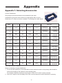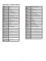
1
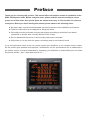
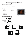
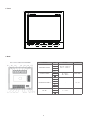
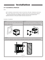
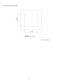
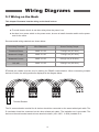
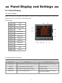
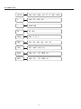
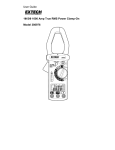
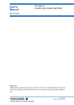
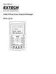
Multi - functional Power Meter DPM - C520 User Manual www.deltaww.com Table of Contents 1. Preface ‧ ‧ ‧ ‧ ‧ ‧ ‧ ‧ ‧ ‧ ‧ ‧ ‧ ‧ ‧ ‧ ‧ ‧ ‧ ‧ ‧ ‧ ‧ ‧ ‧ ‧ ‧ ‧ ‧ ‧ ‧ ‧ ‧ ‧ ‧ ‧ ‧ ‧ ‧ ‧ ‧ ‧ ‧ ‧ ‧ ‧ ‧ ‧ ‧ 2 2. Notes ‧ ‧ ‧ ‧ ‧ ‧ ‧ ‧ ‧ ‧ ‧ ‧ ‧ ‧ ‧ ‧ ‧ ‧ ‧ ‧ ‧ ‧ ‧ ‧ ‧ ‧ ‧ ‧ ‧ ‧ ‧ ‧ ‧ ‧ ‧ ‧ ‧ ‧ ‧ ‧ ‧ ‧ ‧ ‧ ‧ ‧ ‧ ‧ ‧ ‧ 3 2.1 Safety Notes ‧ ‧ ‧ ‧ ‧ ‧ ‧ ‧ ‧ ‧ ‧ ‧ ‧ ‧ ‧ ‧ ‧ ‧ ‧ ‧ ‧ ‧ ‧ ‧ ‧ ‧ ‧ ‧ ‧ ‧ ‧ ‧ ‧ ‧ ‧ ‧ ‧ ‧ ‧ ‧ ‧ ‧ ‧ ‧ ‧ ‧ ‧ ‧ ‧ ‧ ‧ ‧ ‧ ‧ ‧ ‧ ‧ ‧ 3 2.2 Installation Environment ‧ ‧ ‧ ‧ ‧ ‧ ‧ ‧ ‧ ‧ ‧ ‧ ‧ ‧ ‧ ‧ ‧ ‧ ‧ ‧ ‧ ‧ ‧ ‧ ‧ ‧ ‧ ‧ ‧ ‧ ‧ ‧ ‧ ‧ ‧ ‧ ‧ ‧ ‧ ‧ ‧ ‧ ‧ ‧ ‧ ‧ ‧ ‧ 4 3. Descriptions of Parts‧ ‧ ‧ ‧ ‧ ‧ ‧ ‧ ‧ ‧ ‧ ‧ ‧ ‧ ‧ ‧ ‧ ‧ ‧ ‧ ‧ ‧ ‧ ‧ ‧ ‧ ‧ ‧ ‧ ‧ ‧ ‧ ‧ ‧ ‧ ‧ ‧ 5 3.1 Operating Interface ‧ ‧ ‧ ‧ ‧ ‧ ‧ ‧ ‧ ‧ ‧ ‧ ‧ ‧ ‧ ‧ ‧ ‧ ‧ ‧ ‧ ‧ ‧ ‧ ‧ ‧ ‧ ‧ ‧ ‧ ‧ ‧ ‧ ‧ ‧ ‧ ‧ ‧ ‧ ‧ ‧ ‧ ‧ ‧ ‧ ‧ ‧ ‧ ‧ ‧ ‧ ‧ 5 3.2 Product Name Tag ‧ ‧ ‧ ‧ ‧ ‧ ‧ ‧ ‧ ‧ ‧ ‧ ‧ ‧ ‧ ‧ ‧ ‧ ‧ ‧ ‧ ‧ ‧ ‧ ‧ ‧ ‧ ‧ ‧ ‧ ‧ ‧ ‧ ‧ ‧ ‧ ‧ ‧ ‧ ‧ ‧ ‧ ‧ ‧ ‧ ‧ ‧ ‧ ‧ ‧ ‧ ‧ ‧ 5 3.3 Exterior and Dimensions ‧ ‧ ‧ ‧ ‧ ‧ ‧ ‧ ‧ ‧ ‧ ‧ ‧ ‧ ‧ ‧ ‧ ‧ ‧ ‧ ‧ ‧ ‧ ‧ ‧ ‧ ‧ ‧ ‧ ‧ ‧ ‧ ‧ ‧ ‧ ‧ ‧ ‧ ‧ ‧ ‧ ‧ ‧ ‧ ‧ ‧ ‧ ‧ 5 4. Installation‧ ‧ ‧ ‧ ‧ ‧ ‧ ‧ ‧ ‧ ‧ ‧ ‧ ‧ ‧ ‧ ‧ ‧ ‧ ‧ ‧ ‧ ‧ ‧ ‧ ‧ ‧ ‧ ‧ ‧ ‧ ‧ ‧ ‧ ‧ ‧ ‧ ‧ ‧ ‧ ‧ ‧ ‧ ‧ ‧ ‧ 7 4.1 Installation Method ‧ ‧ ‧ ‧ ‧ ‧ ‧ ‧ ‧ ‧ ‧ ‧ ‧ ‧ ‧ ‧ ‧ ‧ ‧ ‧ ‧ ‧ ‧ ‧ ‧ ‧ ‧ ‧ ‧ ‧ ‧ ‧ ‧ ‧ ‧ ‧ ‧ ‧ ‧ ‧ ‧ ‧ ‧ ‧ ‧ ‧ ‧ ‧ ‧ ‧ ‧ ‧ ‧ 7 4.2 Basic Checks ‧ ‧ ‧ ‧ ‧ ‧ ‧ ‧ ‧ ‧ ‧ ‧ ‧ ‧ ‧ ‧ ‧ ‧ ‧ ‧ ‧ ‧ ‧ ‧ ‧ ‧ ‧ ‧ ‧ ‧ ‧ ‧ ‧ ‧ ‧ ‧ ‧ ‧ ‧ ‧ ‧ ‧ ‧ ‧ ‧ ‧ ‧ ‧ ‧ ‧ ‧ ‧ ‧ ‧ ‧ ‧ ‧ 9 5. Wiring Diagrams‧ ‧ ‧ ‧ ‧ ‧ ‧ ‧ ‧ ‧ ‧ ‧ ‧ ‧ ‧ ‧ ‧ ‧ ‧ ‧ ‧ ‧ ‧ ‧ ‧ ‧ ‧ ‧ ‧ ‧ ‧ ‧ ‧ ‧ ‧ ‧ ‧ ‧ ‧ ‧ 10 5.1 Wiring on the Back ‧ ‧ ‧ ‧ ‧ ‧ ‧ ‧ ‧ ‧ ‧ ‧ ‧ ‧ ‧ ‧ ‧ ‧ ‧ ‧ ‧ ‧ ‧ ‧ ‧ ‧ ‧ ‧ ‧ ‧ ‧ ‧ ‧ ‧ ‧ ‧ ‧ ‧ ‧ ‧ ‧ ‧ ‧ ‧ ‧ ‧ ‧ ‧ ‧ ‧ ‧ ‧ 10 5.2 Descriptions of Wiring ‧ ‧ ‧ ‧ ‧ ‧ ‧ ‧ ‧ ‧ ‧ ‧ ‧ ‧ ‧ ‧ ‧ ‧ ‧ ‧ ‧ ‧ ‧ ‧ ‧ ‧ ‧ ‧ ‧ ‧ ‧ ‧ ‧ ‧ ‧ ‧ ‧ ‧ ‧ ‧ ‧ ‧ ‧ ‧ ‧ ‧ ‧ ‧ ‧ 11 6. Panel Display and Settings ‧ ‧ ‧ ‧ ‧ ‧ ‧ ‧ ‧ ‧ ‧ ‧ ‧ ‧ ‧ ‧ ‧ ‧ ‧ ‧ ‧ ‧ ‧ ‧ ‧ ‧ ‧ ‧ ‧ ‧ 13 6.1 Panel Display ‧ ‧ ‧ ‧ ‧ ‧ ‧ ‧ ‧ ‧ ‧ ‧ ‧ ‧ ‧ ‧ ‧ ‧ ‧ ‧ ‧ ‧ ‧ ‧ ‧ ‧ ‧ ‧ ‧ ‧ ‧ ‧ ‧ ‧ ‧ ‧ ‧ ‧ ‧ ‧ ‧ ‧ ‧ ‧ ‧ ‧ ‧ ‧ ‧ ‧ ‧ ‧ ‧ ‧ ‧ ‧ 13 6.2 General Operations ‧ ‧ ‧ ‧ ‧ ‧ ‧ ‧ ‧ ‧ ‧ ‧ ‧ ‧ ‧ ‧ ‧ ‧ ‧ ‧ ‧ ‧ ‧ ‧ ‧ ‧ ‧ ‧ ‧ ‧ ‧ ‧ ‧ ‧ ‧ ‧ ‧ ‧ ‧ ‧ ‧ ‧ ‧ ‧ ‧ ‧ ‧ ‧ ‧ ‧ ‧ 15 6.3 Setup Operations ‧ ‧ ‧ ‧ ‧ ‧ ‧ ‧ ‧ ‧ ‧ ‧ ‧ ‧ ‧ ‧ ‧ ‧ ‧ ‧ ‧ ‧ ‧ ‧ ‧ ‧ ‧ ‧ ‧ ‧ ‧ ‧ ‧ ‧ ‧ ‧ ‧ ‧ ‧ ‧ ‧ ‧ ‧ ‧ ‧ ‧ ‧ ‧ ‧ ‧ ‧ ‧ ‧ 16 7. Parameters and Functions ‧ ‧ ‧ ‧ ‧ ‧ ‧ ‧ ‧ ‧ ‧ ‧ ‧ ‧ ‧ ‧ ‧ ‧ ‧ ‧ ‧ ‧ ‧ ‧ ‧ ‧ ‧ ‧ ‧ ‧ ‧ 22 7.1 Overview of Parameters ‧ ‧ ‧ ‧ ‧ ‧ ‧ ‧ ‧ ‧ ‧ ‧ ‧ ‧ ‧ ‧ ‧ ‧ ‧ ‧ ‧ ‧ ‧ ‧ ‧ ‧ ‧ ‧ ‧ ‧ ‧ ‧ ‧ ‧ ‧ ‧ ‧ ‧ ‧ ‧ ‧ ‧ ‧ ‧ ‧ ‧ ‧ 22 8. Messages of Abnormal Operations ‧ ‧ ‧ ‧ ‧ ‧ ‧ ‧ ‧ ‧ ‧ ‧ ‧ ‧ ‧ ‧ ‧ ‧ ‧ ‧ ‧ ‧ ‧ 37 9. Specifications ‧ ‧ ‧ ‧ ‧ ‧ ‧ ‧ ‧ ‧ ‧ ‧ ‧ ‧ ‧ ‧ ‧ ‧ ‧ ‧ ‧ ‧ ‧ ‧ ‧ ‧ ‧ ‧ ‧ ‧ ‧ ‧ ‧ ‧ ‧ ‧ ‧ ‧ ‧ ‧ ‧ ‧ 38 9.1 Specifications ‧ ‧ ‧ ‧ ‧ ‧ ‧ ‧ ‧ ‧ ‧ ‧ ‧ ‧ ‧ ‧ ‧ ‧ ‧ ‧ ‧ ‧ ‧ ‧ ‧ ‧ ‧ ‧ ‧ ‧ ‧ ‧ ‧ ‧ ‧ ‧ ‧ ‧ ‧ ‧ ‧ ‧ ‧ ‧ ‧ ‧ ‧ ‧ ‧ ‧ ‧ ‧ ‧ ‧ ‧ ‧ 38 9.2 Communication Specifications ‧ ‧ ‧ ‧ ‧ ‧ ‧ ‧ ‧ ‧ ‧ ‧ ‧ ‧ ‧ ‧ ‧ ‧ ‧ ‧ ‧ ‧ ‧ ‧ ‧ ‧ ‧ ‧ ‧ ‧ ‧ ‧ ‧ ‧ ‧ ‧ ‧ ‧ ‧ ‧ ‧ ‧ 39 9.3 MODBUS Communication ‧ ‧ ‧ ‧ ‧ ‧ ‧ ‧ ‧ ‧ ‧ ‧ ‧ ‧ ‧ ‧ ‧ ‧ ‧ ‧ ‧ ‧ ‧ ‧ ‧ ‧ ‧ ‧ ‧ ‧ ‧ ‧ ‧ ‧ ‧ ‧ ‧ ‧ ‧ ‧ ‧ ‧ ‧ ‧ ‧ 40 10. Appendix ‧ ‧ ‧ ‧ ‧ ‧ ‧ ‧ ‧ ‧ ‧ ‧ ‧ ‧ ‧ ‧ ‧ ‧ ‧ ‧ ‧ ‧ ‧ ‧ ‧ ‧ ‧ ‧ ‧ ‧ ‧ ‧ ‧ ‧ ‧ ‧ ‧ ‧ ‧ ‧ ‧ ‧ ‧ ‧ ‧ 43 Appendix 1: Selecting Accessories ‧ ‧ ‧ ‧ ‧ ‧ ‧ ‧ ‧ ‧ ‧ ‧ ‧ ‧ ‧ ‧ ‧ ‧ ‧ ‧ ‧ ‧ ‧ ‧ ‧ ‧ ‧ ‧ ‧ ‧ ‧ ‧ ‧ ‧ ‧ ‧ ‧ ‧ ‧ ‧ ‧ 43 Appendix 2: Abbreviations ‧ ‧ ‧ ‧ ‧ ‧ ‧ ‧ ‧ ‧ ‧ ‧ ‧ ‧ ‧ ‧ ‧ ‧ ‧ ‧ ‧ ‧ ‧ ‧ ‧ ‧ ‧ ‧ ‧ ‧ ‧ ‧ ‧ ‧ ‧ ‧ ‧ ‧ ‧ ‧ ‧ ‧ ‧ ‧ ‧ ‧ ‧ ‧ ‧ 44 1 Preface Thank you for choosing this product. This manual offers information related to installation of the DPM - C530A power meter. Before using the meter, please read this manual carefully to ensure proper use of this meter. Also, please place the manual at an easy - to - find location for reference at any time. Before you finish reading this manual, please observe the following notes: ■ No water vapor, corrosive and fl ammable gas shall be present in the installation environment. ■ Follow the instructions on the diagram for wiring the device. ■ Grounding must be performed correctly and properly according to provisions from related regulations on electric work currently effective in the country. ■ Do not disassemble the meter or alter its wiring with power connected. ■ With power on, do not touch the power - connecting area to avoid electric shock. If you still experience issues in the use, please contact your distributor or our customer service center. As the product gets updated and improved, modifications on the specifications will be addressed in the newest version of manual obtainable by contacting your distributor or downloading from the Delta Electronics website(http: / / www.delta.com.tw / ia / ). 2 Notes 2.1 Safety Notes Always be aware of the following safety notes when installing, wiring, operating, maintaining, and checking the device. ◆ Notes on Installation » Install the power meter according to instructions on the manual. Otherwise, damage on the device might result. DANGER » It is forbidden to expose and use this product in a place present with matters, such as water vapor, corrosive and flammable gas. Otherwise, electric shock, fire, or explosion might result. » Do not install the meter in an environment with a temperature that exceeds range on the specification. Otherwise, inability of the meter to operate normally or damage on the meter might result. » Do not use the meter on an alarm console that might cause personnel injury or death, damage on the device, or system shutdown. ◆ Note on Wiring DANGER » Keep a good grounding on the grounded terminals, as improper grounding might cause abnormal communication, electric shock, or fire. ◆ Notes on Operation » Do not alter wiring with power turned on. Otherwise, electric shock or personnel injury might result. STOP » Do not touch the panel with a sharp item. Otherwise, indentation on the panel might result, which causes the meter to not function normally. ◆ Maintenance and Check » Do not get to inside of the meter. Otherwise, electric shock might result. » Do not take the meter panel apart when the power is on. Otherwise, electric shock might result. STOP » Do not touch the wiring terminals within 10 minutes after turning off power, as the remaining voltage might cause electric shock. » Do not block ventilation ducts when operating the meter. Otherwise, the meter will breakdown because of inadequate heat dissipation. ◆ Methods of Wiring » Do not use voltage that exceeds range specified for the meter. Otherwise, electric shock or fire might result. » When wiring, take apart the quick connector from the main meter body. » Connect only one cord on one plug on the quick connector. » For wrongfully forced unplug, recheck the connecting cord and restart. ◆ Wiring for Communication Circuits » Follow the standard specification on use of wires for communication wiring. » Length of communication wires should be within the specified standard. » Use correct grounding loop to avoid communication issues. » To avoid stronger noise interference that causes the meter to not operate normally, use an independent wiring slot to separate the communication cable for the meter from all power cords and motor power cords. 3 2.2 Installation Environment Before installation, this product must be placed in its packaging box. If not used for a while, be sure to watch for the following when storing the meter, so that the product could be kept under the company's warranty coverage for future maintenance. ■ Place the device in a dry location free of dust. ■ Ambient temperature for the storage location must be within the range of - 20° C to +70° C ( - 4° F to 158° F). ■ Relative humidity for the storage location must be within the range of 5% to 95%, with no condensation. ■ Avoid storing at an environment present with corrosive gas and liquid. ■ Package properly and store on a rack or counter. ■ Suitable installation environment for this product includes: place with no device that generates high amount of heat; place with no water drop, vapor, dust, and oily dust; place with no corrosive and flammable gas; place with no floating dust and metal particles; place with no shaking and interference from electromagnetic noise. 4 Descriptions of Parts 3.1 Operating Interface DPM - C520 uses a LCD display that exhibits four pieces of measurement information on each page. Diagram below is an illustration of the interface. Descriptions: A. Time H. Up key B. Title I. DOWN key C. Load percentage J. NEXT key D. Item K. Submenu E. PULSE light L. F. M. Values FAULT light Unit G. BACK key 3.2 Product Name Tag Model Version Certification MODEL : XXXXXXXXX REV. : XX.XX Input : 80~265VAC, 50/60Hz 100~300VDC MAX 4.6W Serial Number Country XXXXXXXXXXXXXXXX MADE IN XXXXXX 3.3 Exterior and Dimensions 96 SPEC LABEL 96 90 94.1 72.0 22.1 90 5 ◆ Front ◆ Back EA3H-1R01SLDDRT FUNCTION PIN VOLTAGE CURRENT 20V L - N ~ 400V L - N 35V L - L ~ 690V L - L - 80 ~ 265 VAC 100 ~ 300 VDC 400mA MAX. - 1A ~ 5A - 7 ~ +12 VDC - V1 V2 MEASURED VOTAGE V3 Vn L1 / + L2 / - CONTROL POWER I1+ I1 I2+ MEASURED CURRENT I2 - THESE DRAWINGS A PROPERTY OF DELT SHALL NOT BE REPR BASIS FOR THE MAN APPARATUSES OR D I3+ I3 D+ D- RS - 485 DIMENSIONAL TOLERAN <30 :±0.25 >30~100 :±0.35 >100~300 :±0.5 ABOVE 300 :±0.6 SCALE 1 2 6 DECIM X :± X.X :± X.XX:± UNIT Installation 4.1 Installation Method Note : ■ The installation method should be based on instructions. Otherwise, breakdown would result. ■ For better effectiveness of cooling cycles, sufficient space must be kept between adjacent objects and walls during the installation. Otherwise, imperfect cooling would result. ■ Maximal thickness for the panel installed should not exceed 5 mm. Illustration of Installation : Step 1: Step 2: Open the square hole on the metal plate and then Install the fixing mount into the sliding slot and install the power meter. then push the meter in to touch the metal plate. Step 3: During the installation, reserve a 50 mm - wide space behind the power meter for dissipating heat 50 Unit: mm 7 Dimensions of Panel Hole : Unit: mm (inches) 8 4.2 Basic Checks Items Checked Contents of Checks ■ Regularly check for losing of the fixing mount at the location where the power meter and device are connected. General Check ■ Guard against entrance of foreign objects, such as oil, water, or metal powder at the heat dissipating holes. Guard against entrance of drill cut powders into the power meter. ■ Should the power meter be installed at a place present with harmful gas or dust, guard against entrance of those matters into the meter. ■ Insulate the connecting spot of the wiring terminals. Pre - operation Check (not supplied with control power) ■ Communications wiring should be done properly, or abnormal operations might result. ■ Check for presence of conducive and flammable objects, such as screws or metal pieces, in the power meter. ■ Should electronic devices used near the power meter experience electromagnetic interference, tune with instruments to reduce electromagnetic interference. ■ Check for correct voltage level for the power supplied to the power meter. Pre - running Check (supplied with control power) ■ Check whether power indicator light is lit. ■ Check whether communication between every device is normal. ■ If there is any abnormal response from the power meter, contact your distributor or our customer service center. 9 Wiring Diagrams 5.1 Wiring on the Back This chapter illustrates how the wiring on the back is done. Note: ■ To avoid electric shock, do not alter wiring when the power is on. ■ As there is no power switch on the power meter, be sure to install a breaker switch on the power cord for the meter. Recommended wiring materials are shown below: Connecting Terminals Wire Diameters Screw Turning Torque Functional Power AWG 10 ~ 24 7.14 kgf - cm (0.7 N*m) Measured Voltage AWG 10 ~ 26 7.14 kgf - cm (0.7 N*m) Measured Current AWG 14 ~ 22 8.0 kgf - cm (0.79 N*m) RS - 485 AWG 14 ~ 28 2.04 kgf - cm (0.2 N*m) RTwisted pair cables must be used in cabling for RS485 communication. When connecting multiple devices in series, the wiring method is displayed in the diagram below. Terminal Resistor The D+ communication terminal for all devices should be connected on the same twisted pair cable. The D - terminals should be connected on the other twisted pair cable. The insulation net is grounded. The device on the end terminal needs to have terminal resistor (100~120Ω,0.25W) installed on it. 10 5.2 Descriptions of Wiring This chapter illustrates how wiring is done for this panel. ■ Measured Voltage: When measured voltage is higher than the rated specifi cation (refer to Electrical Specifi cation 9.1) for the device, use of an external potential transformer should be considered. ■ Measured Current: When measured current is higher than the rated specifi cation (refer to Electrical Specifi cation 9.1) for the device, use of an external current transformer should be considered. ■ Supported Methods of Wiring: A N A I1+ V1 V2 V3 Vn I1+ I1- I1- I2+ I2+ I2- I2- I3+ I3+ I3- Load B C A V1 V2 V3 V2 V3 Vn Diagram 5 - 2: One - phase three - wire, 2 CT N I1+ V1 I3- Load Diagram 5 - 1: One - phase two - wire, 1 CT A N B B C N I1+ Vn V1 V2 V3 Vn I1- I1- I2+ I2+ I2- I2- I3+ I3+ I3- I3Load Load Diagram 5 - 3: Three - phase three - wire, Diagram 5 - 4: Three - phase three - wire, Δ Delta - connection, 3 CT, No PT Δ Delta - connection, 2 CT, No PT 11 A B C A N N C B I1+ I1+ V1 V2 V3 V1 V2 V3 Vn Vn I1- I1- I2+ I2+ I2- I2I3+ I3+ I3- I3- Load Load Diagram 5 - 5: Three - phase three - wire, Diagram 5 - 6: Three - phase four - wire, Δ Delta - connection, 3 CT, 2 PT Y - connection, 3 CT, No PT A B C A N I1+ V1 V2 V3 B C N I1+ Vn V1 V2 V3 Vn I1- I1- I2+ I2+ I2- I2- I3+ I3+ I3- I3- Load Load Diagram 5 - 7: Three - phase four - wire, Diagram 5 - 8: Three - phase four - wire, Y - connection, 3 CT, 3 PT Y - connection, 2 CT, 3 PT ■ The following symbols are used in the diagram: Symbol Description Grounding Current transformer Terminal resistor 12 Potential or voltage transformer Fuse Panel Display and Settings 6.1 Panel Display 6.1.1 Area of Display DPM - C520 uses LCD display that exhibits four pieces of measurement information on each page. Diagram below is an illustration of the display panel: Descriptions: A Time B Title C Load percentage D Item E PULSE light F FAULT light G BACK key H UP key I DOWN key J NEXT key K Submenu L Unit M Values 6.1.2 Descriptions of the Keys Name of Key BACK key General Mode Confi guration Mode Enter into Menu or return to previous page Return without saving current settings Move up to select an item or page Increase numbers DOWN key Move down to select an item or page Decrease numbers NEXT key Enter into the selected item Enter into the setting and move to the next location of setting UP key 13 6.1.3 Menu Tree 1. Time, date SETUP TIM DAT COM SYS CT PT RST INFO V VLN VLL ULN ULL 2. Meter information 3. Communication parameter 4.CT, PT proportion I 5. System parameter AMP UNB 6. Alarm PF DPF7. Demand PF 0. Setting PWR 8. Reset PQS P Q S 1. Voltage Measure ENG THD MAX Phase voltage Line voltage Unbalanced phase voltage % Unbalanced line voltage % +Ph -PhCurrent +Qh -Qh Unbalanced +Sh -Sh 2. Current measure 3. PF / Hz current % Power factor TOT AMP VLN VLLDisplacement PF Frequency 4. Power measure Total power Active power Reactive power Apparent power 5. Energy measure Active energy Reactive energy Apparent energy Automatic energy 1 VLN VLL I PF PWR Hz MIN VLN VLL I PF PWR Hz 6.Harmonics Total harminics Current THD Phase voltage THD 7. Demanics Current demand Active power demand Reactive power demand 8.Maximum Apparent power demand 1. Current 9. Minimum 1. Current 2. Voltage 10.Alarm History 2. Voltage 3. Power 11. Advanced 1. Area 3. Power 4. Power factor 2. Auto mation 4. Power factor 5. Frequency 3. Data Log 5. Frequency 6. Harmonics 6. Harmonics 14 Automatic energy 2 6.2 General Operations 6.2.1 Reading Measured Data ■ Voltage Measurement: Parameter of voltage measured by the power meter, including voltage L - N, voltage L - N, voltage L - N unbalance, voltage L - L unbalance, etc. ■ Current Measurement: Parameter of current measured by the meter, including current, current unbalance, and others. ■ Power Factor, Frequency (PF, Hz): Power factor and parameter of frequency measured by the meter, including power factor, displacement power factor, frequency, and others. ■ Power Measurement: Parameter of power measured by the meter, including active, reactive, and apparent power per phase and total. ■ Energy Measurement: Parameter of electrical energy measured by the meter, including active, reactive, and apparent electrical energy as delivered and received. ■ Harmonic: Parameter of harmonic measured by the meter, including total harmonic distortion for voltage and current. ■ Maximum: Maximum parameter measured by the meter, including maximum value of voltage, current, power factor, frequency, power. ■ Minimum: Minimum parameter measured by the meter, including minimum value of voltage, current, power factor, frequency, power. ■ Alarm: Parameter of alarms for the meter. (1) Press the BACK key until HOME appears. (2) Select an item that you want to take a look at. (3) Press the BACK key to return to the HOME page. Example: Press the BACK key to show the HOME page. Using UP, DOWN and NEXT keys to switch to pages for voltage L - N, voltage L - L, voltage L - N unbalance and voltage L - L unbalance. 15 6.3 Setup Operations 6.3.1 Time Settings ■ Time: Current time on the meter, including hour, minute. ■ Steps to set up are as follows: (1) Press BACK key until HOME appears. (2) Press Setup (BACK Key) to enter the setup page. ▲ (3) Press (NEXT key) until TIM appears and press UP key to enter the TIME setting page (4) When the option HH is highlighted, start set up by using the Up and Down keys to select the numbers needed (5) Press SET (NEXT key) to finish setting and move on to next one. (6) When the option MM is highlighted, start set up by using the Up and Down keys to select the numbers needed. (7) Press SET (NEXT Key) to finish setting. (8) Press BACK key to cancel the changes without saving. 6.3.2 Date Settings ■ Date: Current date on the meter, including year, month and day. ■ Steps to set up are as follows: (1) Press BACK key until HOME appears. (2) Press Setup (BACK Key) to enter the setup page. ▲ (3) Press (NEXT key) until DAT appears and press DOWN key to enter the DAT setting page. (4) When the option YY is highlighted, start set up by using the Up and Down keys to select the numbers needed. (5) Press SET (NEXT key) to finish setting and move on to the next one (MM). (6) When the option MM is highlighted, start set up by using the Up and Down keys to select the numbers needed. (7) Press SET (NEXT Key) to finish setting and move on to the next one (DD). (8) When the option DD is highlighted, start set up by using the Up and Down keys to select the numbers needed. (9) Press SET (NEXT Key) to finish setting. (10) Press BACK key to cancel the changes without saving. 16 6.3.3 Potential and Current Transformers Setting ■ Address: Range of address for the device is 1 ~ 254, with the broadcast address of 255 and factory default of 1. ■ Baud Rate: Speed of communication transmission, with the factory default of 9600 kbps. ■ Parity: 8O1, 8N1 (default) and 8E1 can be selected. ■ Steps to set up are as follows: (1) Press BACK key until HOME appears. ▲ (2) Press (NEXT key) until COM appears and press UP key to enter the COM setting page (3) When the option is highlighted, start set up by using the Up and Down keys to select the numbers needed. (4) Press SET (NEXT key) to finish set up for a number and move on to set up for the next number. (5) Repeat steps (3) ~ (5) until finishing setup for the last number and press the SET (NEXT key). When the highlight disappears, setup is complete. Press BACK key to cancel the changes without saving. (6) Baud rate and parity can be setup as above. 6.3.4 System Parameters Setting ■ Power System: Selection of wiring method for the system, with a selection of one - phase two - wire, one - phase three - wire, three - phase three - wire, three - phase four - wire (factory default). ■ Number of CTs: Numbers of current transformers on the system. 0, 1, 2, 3 current transformers are selectable. The default setting of current transformers is 3. ■ Number of PTs: Numbers of potential transformers on the system. 0, 2, 3 potential transformers are selectable. The default setting of potential transformers is 3. ■ Steps to set up are as follows: (1) Press BACK key until HOME appears. ▲ (2) Press (NEXT key) until SYS appears and press DOWN key to enter into the SYS setting page. (3) When the option is highlighted, start set up by using the Up and Down keys to select the mode needed. (4) Press SET (NEXT) key to finish set up and move on to the next one (CT). (5) When the option is highlighted, start set up by using the Up and Down keys to select the number needed. 17 (6) Press SET (NEXT) key to finish set up and move on to the next one (PT). (7) When the option is highlighted, start set up by using the Up and Down keys to select the number needed. (8) Press the BACK key to cancel the changes without saving. 6.3.5 Current Transformers Setting ■ Primary - side current transformer (CT1): Ampere for the primary - side current transformer, with a selectable range of 1 ~ 9999 A (factory default: 1 A). ■ Secondary - side current transformer (CT2): Ampere for the secondary - side current transformer, with a selection of 1 and 5 A (factory default: 1 A). ■ Steps to set up are as follows: (1) Press BACK key until HOME appears. ▲ (2) Press (NEXT key) until CT appears and press UP key to enter into the CT setting page (3) When the option is highlighted, start set up by using the Up and Down keys to select the numbers needed. (4) Press SET (NEXT key) to finish set up for a number and move on to set up for the next number. (5) Repeat steps (3) ~ (5) until finishing setup for the last number and press the SET (NEXT key). When the highlight disappears, setup is complete. (6) Press the BACK key to cancel the changes without saving. 6.3.6 Potential Transformers Setting ■ Primary - side potential transformer (PT1): Voltage for the primary - side potential transformer, with a selectable range of 1 ~ 9999 V (factory default: 1V). ■ Secondary - side potential transformer (PT2): Voltage for the secondary - side potential transformer, with a selectable range of 1 ~ 9999 V (factory default: 1V). ■ Steps to set up are as follows: (1) Press BACK key until HOME appears. ▲ (2) Press (NEXT key) until PT appears and press the DOWN key to enter the PT setting page. (3) When the option is highlighted, start set up by using the Up and Down keys to select the numbers needed. 18 (4) Press SET (NEXT key) to finish set up for a number and move on to set up for the next number. (5) Repeat steps (3) ~ (5) until finishing setup for the last number and press the SET (NEXT key). When the highlight disappears, setup is complete. (6) Press the BACK key to cancel the changes without saving. 6.3.7 Restore Settings ■ Default: Restores settings on the meter to factory default. ■ Energy: Resets to zero for the value of electrical energy accumulated on the meter. ■ MaxMin: Clears all records of maximum and minimum values logged on the meter. ■ Alarm: Clears all alarm logs detected on the meter. ■ Steps to set up are as follows: (1) Press BACK key until HOME appears. (3) Press ▲ ▲ (2) Press (NEXT key) until RST appears and press UP key to enter the RST setting page. (NEXT key) until DEF appears and press UP key to enter the DEF setting page. (4) Press SET (NEXT key) to restore the power meter to default setting. ▲ (5) Press (NEXT key) until ENG appears on RST setting page. (6) Press DOWN key to enter the ENG setting page. (7) Press SET (NEXT key) to clear the value of energy accumulated on the meter. ▲ (8) Press (NEXT key) until MM appears on RST setting page. (9) Press UP key to enter into the MAXMIN setting page. (10)Press SET (NEXT key) to clear the records of maximum and minimum values logged on the meter. ▲ (11) Press (NEXT key) until ALA appears on RST setting page. (12)Press DOWN key to enter into the ALA setting page. (13)Press SET (NEXT key) to clear all alarm logs detected on the meter. 19 6.3.8 Alarm Settings ■ Alarm: Whether this alarm is enabled or disabled (factory default). ■ Pickup setpoint: When the threshold set on the meter is exceeded, an alarm is triggered. The factory default is 0. ■ Dropout setpoint: When the threshold set on the meter falls short, the alarm is cleared. The factory default is 0. ■ Steps to set up are as follows: Configure the alarm setting, alarm enable, pickup setpoint and dropout setting which MODBUS address are 0x1F ~ 0xB8 for each alarms. Pickup Setpoint Dropout Setpoint Alarm period 1 Sec 1 Sec 20 6.3.9 Parameter grouping ■ Parameter grouping: block of MODBUS address mirrored from standard selected MODBUS address that allows meter value, MODBUS address 0x100 ~ 0x18B, can be gathered with single MODBUS block read. Default value is 0xFFFF. ■ Steps to set up are as follows: (1) Configure MODBUS address 0x50c ~ 0x515 with selected MODBUS address of meter value by MODBUS function code 0x06 or 0x10. (2) Read MODBUS address 0x600 ~ 0x609 for selected meter values with MODBUS function code 0x3 after Step 1 is complete. Example: 1. To mirror the voltage L - N and current value from standard MODBUS address 0x100 ~ 0x101 and 0x126 ~ 0x127 to a continuous block MODBUS address which can be gathered with single MODBUS block read command: Write 0x100 and 0x101 (the MODBUS address of voltage L - N) into MODBUS address 0x50C and 0x50D with function code 0x06 (single write) or 0x10 (multi write). Write 0x126 and 0x127(the MODBUS address of current) into MODBUS address 0x50E and 0x50F with function code 0x06 (single write) or 0x10 (multi write). Other MODBUS address is shown in 7.1 Address Table. 2. After step1 is finished, voltage L - N and current value can be gathered with a single MODBUS block read of address 0x50C ~ 0x50F through MODBUS function code 0x03. Voltage L - N and current value are in IEEE754 format. Other MODBUS address data types are shown in the 7.1 Address Table. 21 Parameters and Functions 7.1 Overview of Parameters MODBUS Address Hex Data Type Unit Data Size (Byte) Read (R) / Write (W) year: 00 ~ 99 month: 1 ~ 12 byte year, month 2 R / W day:1 ~ 31 week: Sun. ~ Sat. byte day, week 2 R / W hour: 00 ~ 23 minute: 00 ~ 59 byte hour and minute 2 R / W second: 00 ~ 59 word second 2 R / W Item Communicated Modicom Format Range 0. System Parameter: 0001 ~ 00FF 1 40002 Present date 2 40003 3 40004 4 40005 5 40006 Meter constant 3200 uint P / kWh 2 R 6 40007 Meter model 0: None 2: DPMC520 word 2 R 7 40008 day: 0 ~ 65535 uint day 2 R 8 40009 hour: 00 ~ 23 minute: 00 ~ 59 byte hour, minute 2 R 9 40010 0.0000 ~ 9.9999 uint 2 R A 40011 year: 00 ~ 99 month: 1 ~ 12 byte year, month 2 R B 40012 day: 1 ~ 31 word day 2 R C 40013 Present time Total time on power Firmware version Data / Time of Last firmware download Reserved word 2 R / W D 40014 Power system configuration 0: 3φ4W 1: 3φ3W 2: 1φ2W 3: 1φ3W E 40015 CT primary(A) 1 ~ 9999 uint A 2 R / W F 40016 CT secondary(A) 0: 1A 1: 5A word A 2 R / W 10 40017 PT primary 1 ~ 9999 uint V 2 R / W 11 40018 PT secondary 1 ~ 9999 uint V 2 R / W word 2 R / W 12 40019 Quantity of transformer 0: 3CT3PT 1: 3CT2PT 2: 3CT0PT 3: 2CT3PT 4: 2CT2PT 5: 2CT0PT 6: 1CT3PT 7: 1CT2PT 8: 1CT0PT 13 40020 Reserved 14 40021 Reserved 15 40022 Reserved 16 40023 Baud rate 0: 9600 1: 19200 2: 38400 word bps 2 R / W 17 40024 Communication mode 1: RTU word 2 R / W 18 40025 Data bit 0: 8 word bit 2 R / W 22 19 40026 Parity 0: None 1: Even 2: Odd word 2 R / W 1A 40027 Stop bit 0: 1 word bit 2 R / W 1B 40028 MODBUS address 0 ~ 255 word 2 R / W 0: None 1: Reset factory default 3: Clear alarm logs and times 2 W 4: Reset maximum and minimum values 1C 40029 Meter reset 2: Reset value of energy word 1D 40030 Reserved 1E 40031 Reserved word 2 R / W Float A 4 R / W Alarm - Over Current 1F 40032 20 40033 21 40034 22 40035 23 40036 24 40037 Alarm Enable 0: Disable 1: Enable Pickup setpoint (current exceeding this 0.000 ~ 99999.999 value, alarm triggered) Reserved Dropout setpoint (current lower than this value, alarm cleared) 0.000 ~ 99999.999 Float A 4 R / W Alarm Enable 0: Disable 1: Enable word 2 R / W Float V 4 R / W Float V 4 R / W Over Voltage L - L 34 40053 35 40054 36 40055 37 40056 38 40057 39 40058 3A 40059 Pickup setpoint (voltage exceeding this 0.000 ~ 99999.999 value, alarm triggered) Reserved Dropout setpoint (voltage lower than this value, alarm cleared) 0.000 ~ 99999.999 Reserved Alarm Enable 0: Disable 1: Enable word 2 R / W Pickup setpoint (voltage lower than this value, alarm triggered) 0.000 ~ 99999.999 Float V 4 R / W Float V 4 R / W word 2 R / W Under Voltage L - L 3B 40060 3C 40061 3D 40062 3E 40063 Reserved 3F 40064 40 40065 Dropout setpoint (voltage exceeding this value, alarm cleared) 0.000 ~ 99999.999 41 40066 Reserved Alarm Enable 0: Disable 1: Enable Over Voltage L - N 42 40067 23 43 40068 44 40069 45 40070 46 40071 47 40072 48 40073 Pickup setpoint (voltage exceeding this 0.000 ~ 99999.999 value, alarm triggered) Float V 4 R / W Float V 4 R / W Reserved Dropout setpoint (voltage lower than this value, alarm cleared) 0.000 ~ 99999.999 Reserved Alarm Enable 0: Disable 1: Enable word 2 R / W Pickup setpoint (voltage lower than this value, alarm triggered) 0.000 ~ 99999.999 Float V 4 R / W Reserved Dropout setpoint (voltage exceeding this value, alarm cleared) 0.000 ~ 99999.999 Float V 4 R / W Alarm Enable 0: Disable 1: Enable word 2 R / W Pickup setpoint (active power exceeding this value, alarm triggered) 0.000 ~ 99999.999 Float kW 4 R / W Reserved Dropout setpoint (active power lower than this value, alarm cleared) 0.000 ~ 99999.999 Float kW 4 R / W Reserved Under Voltage L - N 49 40074 4A 40075 4B 40076 4C 40077 4D 40078 4E 40079 Over Active Power 5E 40095 5F 40096 60 40097 61 40098 62 40099 63 40100 64 40101 Over Reactive Power 65 40102 66 40103 67 40104 68 40105 69 40106 6A 40107 6B 40108 Alarm Enable 0: Disable 1: Enable word 2 R / W Pickup setpoint (reactive power exceeding this value, alarm triggered) 0.000 ~ 99999.999 Float kVAR 4 R / W Reserved Dropout setpoint (reactive power lower than this value, alarm cleared) 0.000 ~ 99999.999 Float kVAR 4 R / W Reserved Over Apparent Power 6C 40109 6D 40110 6E 40111 6F 40112 70 40113 71 40114 Alarm Enable 0: Disable : Enable word 2 R / W Pickup setpoint (apparent power exceeding this value, alarm triggered) 0.000 ~ 99999.999 Float kVA 4 R / W Reserved Dropout setpoint (apparent power lower than this value, alarm cleared) 0.000 ~ 99999.999 Float kVA 4 R / W 24 72 40115 Reserved Alarm Enable 0: Disable 1: Enable word 2 R / W Pickup setpoint (frequency exceeding this value, alarm triggered) 0.0000 ~ 99.9999 Float Hz 4 R / W Reserved Float Hz 4 R / W Over Frequency AB 40172 AC 40173 AD 40174 AE 40175 AF 40176 B0 40177 B1 40178 Dropout setpoint (frequency lower than 0.0000 ~ 99.9999 this value, alarm cleared) Reserved Alarm Enable 0: Disable 1: Enable word 2 R / W Pickup setpoint (frequency lower than this value, alarm triggered) 0.0000 ~ 99.9999 Float Hz 4 R / W Reserved Float Hz 4 R / W Under Frequency B2 40179 B3 40180 B4 40181 B5 40182 B6 40183 B7 40184 B8 40185 Dropout setpoint (frequency exceeding 0.0000 ~ 99.9999 this value, alarm cleared) Reserved 1.Meter Parameters: 0100 ~ 01FF 100 40257 101 40258 102 40259 103 40260 104 40261 105 40262 106 40263 107 40264 108 40265 109 40266 10A 40267 10B 40268 10C 40269 10D 40270 10E 40271 10F 40272 110 40273 111 40274 Voltage A - N 0.000 ~ 99999.999 Float V 4 R Voltage B - N 0.000 ~ 99999.999 Float V 4 R Voltage C - N 0.000 ~ 99999.999 Float V 4 R Voltage L - N Avg 0.000 ~ 99999.999 Float V 4 R Voltage A - B 0.000 ~ 99999.999 Float V 4 R Voltage B - C 0.000 ~ 99999.999 Float V 4 R Voltage C - A 0.000 ~ 99999.999 Float V 4 R Voltage L - L Avg 0.000 ~ 99999.999 Float V 4 R Voltage unbalance A - N 0.00 ~ 99.99 Float % 4 R 25 112 40275 113 40276 114 40277 115 40278 116 40279 117 40280 118 40281 119 40282 11A 40283 11B 40284 11C 40285 11D 40286 11E 40287 11F 40288 120 40289 121 40290 122 40291 123 40292 124 40293 125 40294 126 40295 127 40296 128 40297 129 40298 12A 40299 12B 40300 12C 40301 12D 40302 12E 40303 12F 40304 130 40305 131 40306 132 40307 133 40308 134 40309 135 40310 136 40311 137 40312 Voltage unbalance B - N 0.00 ~ 99.99 Float % 4 R Voltage unbalance C - N 0.00 ~ 99.99 Float % 4 R Voltage unbalance L - N Avg 0.00 ~ 99.99 Float % 4 R Voltage unbalance A - B 0.00 ~ 99.99 Float % 4 R Voltage unbalance B - C 0.00 ~ 99.99 Float % 4 R Voltage unbalance C - A 0.00 ~ 99.99 Float % 4 R Voltage unbalance L - L Avg 0.00 ~ 99.99 Float % 4 R Current A 0.000 ~ 99999.999 Float A 4 R Current B 0.000 ~ 99999.999 Float A 4 R Current C 0.000 ~ 99999.999 Float A 4 R Current Avg 0.000 ~ 99999.999 Float A 4 R Current N 0.000 ~ 99999.999 Float A 4 R Current unbalance A 0.00 ~ 99.99 Float % 4 R Current unbalance B 0.00 ~ 99.99 Float % 4 R Current unbalance C 0.00 ~ 99.99 Float % 4 R Current unbalance Avg 0.00 ~ 99.99 Float % 4 R Power factor total 0.00000 ~ 1.00000 (positive: lag negative: lead) Float 4 R Power factor A 0.00000 ~ 1.00000 (positive: lag negative: lead) Float 4 R Power factor B 0.00000 ~ 1.00000 (positive: lag negative: lead) Float 4 R 26 138 40313 139 40314 13A 40315 13B 40316 13C 40317 13D 40318 13E 40319 13F 40320 140 40321 141 40322 142 40323 143 40324 144 40325 145 40326 146 40327 147 40328 148 40329 149 40330 14A 40331 14B 40332 14C 40333 14D 40334 14E 40335 14F 40336 150 40337 151 40338 152 40339 153 40340 154 40341 155 40342 156 40343 157 40344 158 40345 159 40346 15A 40347 15B 40348 Power factor C 0.00000 ~ 1.00000 (positive: lag negative: lead) Float 4 R Displacement power factor total 0.00000 ~ 1.00000 (positive: lag negative: lead) Float 4 R Displacement power factor A 0.00000 ~ 1.00000 (positive: lag negative: lead) Float 4 R Displacement power factor B 0.00000 ~ 1.00000 (positive: lag negative: lead) Float 4 R Displacement power factor C 0.00000 ~ 1.00000 (positive: lag negative: lead) Float 4 R Frequency 0.0000 ~ 99.9999 Float Hz 4 R Active power total 0.000 ~ 99999.999 Float kW 4 R Active power A 0.000 ~ 99999.999 Float kW 4 R Active power B 0.000 ~ 99999.999 Float kW 4 R Active power C 0.000 ~ 99999.999 Float kW 4 R Reactive power total 0.000 ~ 99999.999 Float kVAR 4 R Reactive power A 0.000 ~ 99999.999 Float kVAR 4 R Reactive power B 0.000 ~ 99999.999 Float kVAR 4 R Reactive power C 0.000 ~ 99999.999 Float kVAR 4 R Apparent power total 0.000 ~ 99999.999 Float kVA 4 R Apparent power A 0.000 ~ 99999.999 Float kVA 4 R Apparent power B 0.000 ~ 99999.999 Float kVA 4 R Apparent power C 0.000 ~ 99999.999 Float kVA 4 R 27 15C 40349 15D 40350 15E 40351 15F 40352 160 40353 161 40354 162 40355 163 40356 164 40357 165 40358 166 40359 167 40360 174 40373 175 40374 176 40375 177 40376 178 40377 179 40378 17C 40381 17D 40382 17E 40383 17F 40384 180 40385 181 40386 182 40387 183 40388 184 40389 185 40390 186 40391 187 40392 188 40393 189 40394 18A 40395 18B 40396 Active energy delivered 0x00000000 ~ 0xFFFFFFFF uint Wh 4 R Active energy received 0x00000000 ~ 0xFFFFFFFF uint Wh 4 R Reactive energy delivered 0x00000000 ~ 0xFFFFFFFF uint VARh 4 R Reactive energy received 0x00000000 ~ 0xFFFFFFFF uint VARh 4 R Apparent energy delivered 0x00000000 ~ 0xFFFFFFFF uint VAh 4 R Apparent energy received 0x00000000 ~ 0xFFFFFFFF uint VAh 4 R THD current A 0.000 ~ 999.999 Float % 4 R THD current B 0.000 ~ 999.999 Float % 4 R THD current C 0.000 ~ 999.999 Float % 4 R THD voltage A - N 0.000 ~ 999.999 Float % 4 R THD voltage B - N 0.000 ~ 999.999 Float % 4 R THD voltage C - N 0.000 ~ 999.999 Float % 4 R THD voltage A - B 0.000 ~ 999.999 Float % 4 R THD voltage B - C 0.000 ~ 999.999 Float % 4 R THD voltage C - A 0.000 ~ 999.999 Float % 4 R THD current - Avg 0.000 ~ 999.999 Float % 4 R THD voltage - Avg 0.000 ~ 999.999 Float % 4 R 0.000 ~ 99999.999 Float V 4 R 2. Maximum Values: 0200 ~ 02FF 200 40513 201 40514 Max voltage A - B 28 202 40515 203 40516 204 40517 205 40518 206 40519 207 40520 208 40521 209 40522 20A 40523 20B 40524 20C 40525 20D 40526 20E 40527 20F 40528 210 40529 211 40530 212 40531 213 40532 214 40533 215 40534 216 40535 217 40536 218 40537 219 40538 21A 40539 21B 40540 21C 40541 21D 40542 21E 40543 21F 40544 220 40545 221 40546 222 40547 223 40548 224 40549 225 40550 Max voltage A - B date Max voltage A - B time Max voltage B - C Max voltage B - C date Max voltage B - C time Max voltage C - A Max voltage C - A date Max voltage C - A time Max voltage A - N Max voltage A - N date Max voltage A - N time Max voltage B - N Max voltage B - N date Max voltage B - N time Max voltage C - N Max voltage C - N date Max voltage C - N time Max current A year: 00 ~ 99 month: 1 ~ 12 byte year, month 2 R day: 1 ~ 31 word day 2 R hour: 00 ~ 23 minute: 00 ~ 59 byte hour, minute 2 R second: 00 ~ 59 word second 2 R 0.000 ~ 99999.999 Float V 4 R year: 00 ~ 99 month: 1 ~ 12 byte year, month 2 R day: 1 ~ 31 word day 2 R hour: 00 ~ 23 minute: 00 ~ 59 byte hour, minute 2 R second: 00 ~ 59 word second 2 R 0.000 ~ 99999.999 Float V 4 R year: 00 ~ 99 month: 1 ~ 12 byte year, month 2 R day: 1 ~ 31 word day 2 R hour: 00 ~ 23 minute: 00 ~ 59 byte hour, minute 2 R second: 00 ~ 59 word second 2 R 0.000 ~ 99999.999 Float V 4 R year: 00 ~ 99 month: 1 ~ 12 byte year, month 2 R day: 1 ~ 31 word day 2 R hour: 00 ~ 23 minute: 00 ~ 59 byte hour, minute 2 R second: 00 ~ 59 word second 2 R 0.000 ~ 99999.999 Float V 4 R year: 00 ~ 99 month: 1 ~ 12 byte year, month 2 R day: 1 ~ 31 word day 2 R hour: 00 ~ 23 minute: 00 ~ 59 byte hour, minute 2 R second: 00 ~ 59 word second 2 R 0.000 ~ 99999.999 Float V 4 R year: 00 ~ 99 month: 1 ~ 12 byte year, month 2 R day: 1 ~ 31 word day 2 R hour: 00 ~ 23 minute: 00 ~ 59 byte hour, minute 2 R second: 00 ~ 59 word second 2 R 0.000 ~ 99999.999 Float A 4 R 29 226 40551 227 40552 228 40553 229 40554 22A 40555 22B 40556 22C 40557 22D 40558 22E 40559 22F 40560 230 40561 231 40562 232 40563 233 40564 234 40565 235 40566 236 40567 237 40568 238 40569 239 40570 23A 40571 23B 40572 23C 40573 23D 40574 23E 40575 23F 40576 240 40577 241 40578 242 40579 243 40580 244 40581 245 40582 246 40583 247 40584 248 40585 249 40586 Max current A date Max current A time Max current B Max current B date Max current B time Max current C Max current C date Max current C time Max current N Max current N date Max current N time Max frequency Max frequency date Max frequency time Max power factor Max power factor date Max power factor time Max active power total year: 00 ~ 99 month: 1 ~ 12 byte year, month 2 R day: 1 ~ 31 word day 2 R hour: 00 ~ 23 minute: 00 ~ 59 byte hour, minute 2 R second: 00 ~ 59 word second 2 R 0.000 ~ 99999.999 Float A 4 R year: 00 ~ 99 month: 1 ~ 12 byte year, month 2 R day: 1 ~ 31 word day 2 R hour: 00 ~ 23 minute: 00 ~ 59 byte hour, minute 2 R second: 00 ~ 59 word second 2 R 0.000 ~ 99999.999 Float A 4 R year: 00 ~ 99 month: 1 ~ 12 byte year, month 2 R day: 1 ~ 31 word day 2 R hour: 00 ~ 23 minute: 00 ~ 59 byte hour, minute 2 R second: 00 ~ 59 word second 2 R 0.000 ~ 99999.999 Float A 4 R year: 00 ~ 99 month: 1 ~ 12 byte year, month 2 R day: 1 ~ 31 word day 2 R hour: 00 ~ 23 minute: 00 ~ 59 byte hour, minute 2 R second: 00 ~ 59 word second 2 R 0.0000 ~ 99.9999 Float Hz 4 R year: 00 ~ 99 month: 1 ~ 12 byte year, month 2 R day: 1 ~ 31 word day 2 R hour: 00 ~ 23 minute: 00 ~ 59 byte hour, minute 2 R second: 00 ~ 59 word second 2 R 0.00000 ~ 1.00000 Float 4 R year: 00 ~ 99 month: 1 ~ 12 byte year, month 2 R day: 1 ~ 31 word day 2 R hour: 00 ~ 23 minute: 00 ~ 59 byte hour, minute 2 R second: 00 ~ 59 word second 2 R 0.000 ~ 99999.999 Float kW 4 R 30 24A 40587 24B 40588 24C 40589 24D 40590 24E 40591 24F 40592 250 40593 251 40594 252 40595 253 40596 254 40597 255 40598 256 40599 257 40600 258 40601 259 40602 Max active power total date Max active power total time Max reactive power total Max reactive power total date Max reactive power total time Max apparent power total Max apparent power total date Max apparent power total time year: 00 ~ 99 month: 1 ~ 12 byte year, month 2 R day: 1 ~ 31 word day 2 R hour: 00 ~ 23 minute: 00 ~ 59 byte hour, minute 2 R second: 00 ~ 59 word second 2 R 0.000 ~ 99999.999 Float kVAR 4 R year: 00 ~ 99 month: 1 ~ 12 byte year, month 2 R day: 1 ~ 31 word day 2 R hour: 00 ~ 23 minute: 00 ~ 59 byte hour, minute 2 R second: 00 ~ 59 word second 2 R 0.000 ~ 99999.999 Float kVA 4 R year: 00 ~ 99 month: 1 ~ 12 byte year, month 2 R day: 1 ~ 31 word day 2 R hour: 00 ~ 23 minute: 00 ~ 59 byte hour, minute 2 R second: 00 ~ 59 word second 2 R 0.000 ~ 99999.999 Float V 4 R year: 00 ~ 99 month: 1 ~ 12 byte year, month 2 R day: 1 ~ 31 word day 2 R hour: 00 ~ 23 minute: 00 ~ 59 byte hour, minute 2 R second: 00 ~ 59 word second 2 R 0.000 ~ 99999.999 Float V 4 R year: 00 ~ 99 month: 1 ~ 12 byte year, month 2 R day: 1 ~ 31 word day 2 R hour: 00 ~ 23 minute: 00 ~ 59 byte hour, minute 2 R second: 00 ~ 59 word second 2 R 0.000 ~ 99999.999 Float V 4 R year: 00 ~ 99 month: 1 ~ 12 byte year, month 2 R day: 1 ~ 31 word day 2 R hour: 00 ~ 23 minute: 00 ~ 59 byte hour, minute 2 R second: 00 ~ 59 word second 2 R 3. Minimum Values: 0300 ~ 03FF 300 40769 301 40770 302 40771 303 40772 304 40773 305 40774 306 40775 307 40776 308 40777 309 40778 30A 40779 30B 40780 30C 40781 30D 40782 30E 40783 30F 40784 310 40785 311 40786 Min voltage A - B Min voltage A - B date Min voltage A - B time Min voltage B - C Min voltage B - C date Min voltage B - C time Min voltage C - A Min voltage C - A date Min voltage C - A time 31 312 40787 313 40788 314 40789 315 40790 316 40791 317 40792 318 40793 319 40794 31A 40795 31B 40796 31C 40797 31D 40798 31E 40799 31F 40800 320 40801 321 40802 322 40803 323 40804 324 40805 325 40806 326 40807 327 40808 328 40809 329 40810 32A 40811 32B 40812 32C 40813 32D 40814 32E 40815 32F 40816 330 40817 331 40818 332 40819 333 40820 334 40821 335 40822 Min voltage A - N Min voltage A - N date Min voltage A - N time Min voltage B - N Min voltage B - N date Min voltage B - N time Min voltage C - N Min voltage C - N date Min voltage C - N time Min current A Min current A date Min current A time Min current B Min current B date Min current B time Min current C Min current C date Min current C time 0.000 ~ 99999.999 Float V 4 R year: 00 ~ 99 month: 1 ~ 12 byte year, month 2 R day: 1 ~ 31 word day 2 R hour: 00 ~ 23 minute: 00 ~ 59 byte hour, minute 2 R second: 00 ~ 59 word second 2 R 0.000 ~ 99999.999 Float V 4 R year: 00 ~ 99 month: 1 ~ 12 byte year, month 2 R day: 1 ~ 31 word day 2 R hour: 00 ~ 23 minute: 00 ~ 59 byte hour, minute 2 R second: 00 ~ 59 word second 2 R 0.000 ~ 99999.999 Float V 4 year: 00 ~ 99 month: 1 ~ 12 byte year, month 2 R day: 1 ~ 31 word day 2 R hour: 00 ~ 23 minute: 00 ~ 59 byte hour, minute 2 R second: 00 ~ 59 word second 2 R 0.000 ~ 99999.999 Float A 4 R year: 00 ~ 99 month: 1 ~ 12 byte year, month 2 R day: 1 ~ 31 word day 2 R hour: 00 ~ 23 minute: 00 ~ 59 byte hour, minute 2 R second: 00 ~ 59 word second 2 R 0.000 ~ 99999.999 Float A 4 R year: 00 ~ 99 month: 1 ~ 12 byte year, month 2 R day: 1 ~ 31 word day 2 R hour: 00 ~ 23 minute: 00 ~ 59 byte hour, minute 2 R second: 00 ~ 59 word second 2 R 0.000 ~ 99999.999 Float A 4 R year: 00 ~ 99 month: 1 ~ 12 byte year, month 2 R day: 1 ~ 31 word day 2 R hour: 00 ~ 23 minute: 00 ~ 59 byte hour, minute 2 R second: 00 ~ 59 word second 2 R 32 R 336 40823 337 40824 338 40825 339 40826 33A 40827 33B 40828 33C 40829 33D 40830 33E 40831 33F 40832 340 40833 341 40834 342 40835 343 40836 344 40837 345 40838 346 40839 347 40840 348 40841 349 40842 34A 40843 34B 40844 34C 40845 34D 40846 34E 40847 34F 40848 350 40849 351 40850 352 40851 353 40852 354 40853 355 40854 356 40855 357 40856 358 40857 359 40858 Min current N Min current N date Min current N time Min frequency Min frequency date Min frequency time Min power factor Min power factor date Min power factor time Min total active power Min total active power date Min total active power time Min total reactive power Min total reactive power date Min total reactive power time Min total apparent power Min total apparent power date Min total apparent power time 0.000 ~ 99999.999 Float A 4 R year: 00 ~ 99 month: 1 ~ 12 byte year, month 2 R day: 1 ~ 31 word day 2 R hour: 00 ~ 23、minute: 00 ~ 59 byte hour, minute 2 R second: 00 ~ 59 word second 2 R 0.0000 ~ 99.9999 Float Hz 4 R year: 00 ~ 99 month: 1 ~ 12 byte year, month 2 R day: 1 ~ 31 word day 2 R hour: 00 ~ 23 minute: 00 ~ 59 byte hour, minute 2 R second: 00 ~ 59 word second 2 R 0.00000 ~ 1.00000 Float 4 R year: 00 ~ 99 month: 1 ~ 12 byte year, month 2 R day: 1 ~ 31 word day 2 R hour: 00 ~ 23 minute: 00 ~ 59 byte hour, minute 2 R second: 00 ~ 59 word second 2 R 0.000 ~ 99999.999 Float kW 4 R year: 00 ~ 99 month: 1 ~ 12 byte year, month 2 R day: 1 ~ 31 word day 2 R hour: 00 ~ 23 minute: 00 ~ 59 byte hour, minute 2 R second: 00 ~ 59 word second 2 R 0.000 ~ 99999.999 Float kVAR 4 R year: 00 ~ 99 month: 1 ~ 12 byte year, month 2 R day: 1 ~ 31 word day 2 R hour: 00 ~ 23 minute: 00 ~ 59 byte hour, minute 2 R second: 00 ~ 59 word second 2 R 0.000 ~ 99999.999 Float kVA 4 R year: 00 ~ 99 month: 1 ~ 12 byte year, month 2 R day: 1 ~ 31 word day 2 R hour: 00 ~ 23 minute: 00 ~ 59 byte hour, minute 2 R second: 00 ~ 59 word second 2 R 33 4. Alarm: 0400 ~ 04FF 400 41025 Over current alarm status 0: Cleared 1: Triggered word 2 R 401 41026 Over current alarm counter 1 ~ 255 word times 2 R 402 41027 year: 00 ~ 99 month: 1 ~ 12 byte year, month 2 R 403 41028 day: 1 ~ 31 word day 2 R 404 41029 hour: 00 ~ 23 minute: 00 ~ 59 byte hour, minute 2 R 405 41030 Over current alarm date Over current alarm time second: 00 ~ 59 word second 2 R word 2 R 412 41043 Over voltage L - L alarm status 0: Cleared 1: Triggered 413 41044 Over voltage L - L alarm counter 1 ~ 255 word times 2 R 414 41045 year: 00 ~ 99 month: 1 ~ 12 byte year, month 2 R 415 41046 day: 1 ~ 31 word day 2 R 416 41047 hour: 00 ~ 23 minute: 00 ~ 59 byte hour, minute 2 R 417 41048 second: 00 ~ 59 word second 2 R 418 41049 Under voltage L - L alarm status 0: Cleared 1: Triggered word 2 R 419 41050 Under voltage L - L alarm counter 1 ~ 255 word times 2 R 41A 41051 year: 00 ~ 99 month: 1 ~ 12 byte year, month 2 R 41B 41052 day: 1 ~ 31 word day 2 R 41C 41053 hour: 00 ~ 23 minute: 00 ~ 59 byte hour, minute 2 R 41D 41054 second: 00 ~ 59 word second 2 R 41E 41055 Over voltage L - N alarm status 0: Cleared 1: Triggered word 2 R 41F 41056 Over voltage L - N alarm counter Over voltage L - L alarm date Over voltage L - L alarm time Under voltage L - L alarm date Under voltage L - L alarm time 1 ~ 255 word times 2 R year: 00 ~ 99 month: 1 ~ 12 byte year, month 2 R day: 1 ~ 31 word day 2 R hour: 00 ~ 23 minute: 00 ~ 59 byte hour, minute 2 R second: 00 ~ 59 word second 2 R 420 41057 421 41058 422 41059 423 41060 424 41061 Under voltage L - N alarm status 0: Cleared 1: Triggered word 2 R 425 41062 Under voltage L - N alarm counter 1 ~ 255 word times 2 R 426 41063 year: 00 ~ 99 month: 1 ~ 12 byte year, month 2 R 427 41064 day: 1 ~ 31 word day 2 R 428 41065 hour: 00 ~ 23 minute: 00 ~ 59 byte hour, minute 2 R 429 41066 second: 00 ~ 59 word second 2 R 436 41079 Over active power alarm status 0: Cleared 1: Triggered word 2 R 437 41080 Over active power alarm counter 1 ~ 255 word times 2 R 438 41081 year: 00 ~ 99 month: 1 ~ 12 byte year, month 2 R 439 41082 day: 1 ~ 31 word day 2 R Over voltage L - N alarm date Over voltage L - N alarm time Under voltage L - N alarm date Under voltage L - N alarm time Over active power alarm date 34 hour: 00 ~ 23 minute: 00 ~ 59 byte hour, minute 2 R second: 00 ~ 59 word second 2 R Over reactive power alarm status 0: Cleared 1: Triggered word 2 R Over reactive power alarm counter 1 ~ 255 word times 2 R year: 00 ~ 99 month: 1 ~ 12 byte year, month 2 R day: 1 ~ 31 word day 2 R hour: 00 ~ 23 minute: 00 ~ 59 byte hour, minute 2 R second: 00 ~ 59 word second 2 R 0: Cleared 1: Triggered word 2 R 43A 41083 43B 41084 43C 41085 43D 41086 43E 41087 43F 41088 440 41089 441 41090 442 41091 Over apparent power alarm status 443 41092 Over apparent power alarm counter Over active power alarm time Over reactive power alarm date Over reactive power alarm time 1 ~ 255 word times 2 R year: 00 ~ 99 month: 1 ~ 12 byte year, month 2 R day: 1 ~ 31 word day 2 R hour: 00 ~ 23 minute: 00 ~ 59 byte hour, minute 2 R second: 00 ~ 59 word second 2 R 444 41093 445 41094 446 41095 447 41096 478 41145 Over frequency alarm status 0: Cleared 1: Triggered word 2 R 479 41146 Over frequency alarm counter 1 ~ 255 word times 2 R 47A 41147 year: 00 ~ 99 month: 1 ~ 12 byte year, month 2 R 47B 41148 day: 1 ~ 31 word day 2 R 47C 41149 hour: 00 ~ 23 minute: 00 ~ 59 byte hour, minute 2 R 47D 41150 second: 00 ~ 59 word second 2 R 47E 41151 Under frequency alarm status 0: Cleared 1: Triggered word 2 R 47F 41152 Under frequency alarm counter 1 ~ 255 word times 2 R 480 41153 byte year, month 2 R 481 41154 Under frequency alarm date year: 00 ~ 99 month: 1 ~ 12 day: 1 ~ 31 word day 2 R 482 41155 hour: 00 ~ 23 minute: 00 ~ 59 byte hour, minute 2 R 483 41156 second: 00 ~ 59 word second 2 R Over apparent power alarm date Over apparent power alarm time Over frequency alarm date Over frequency alarm time Under frequency alarm time 5. Advanced Settings: 0500 ~ 05FF 0x100 ~ 0x18B word 2 R / W 50D 41294 Parameter grouping #2 setting 0x100 ~ 0x18B word 2 R / W 0x100 ~ 0x18B word 2 R / W Parameter grouping #10 setting 0x100 ~ 0x18B word 2 R / W byte year, month 2 R 515 41302 … Parameter grouping #1 setting … 41293 … 50C 552 41363 Reset energy date year: 00 ~ 99 month: 1 ~ 12 553 41364 Reset energy date day: 1 ~ 31 word day 2 R 554 41365 Reset energy time hour: 00 ~ 23 minute: 00 ~ 59 byte hour, minute 2 R 35 555 41366 Reset energy time second: 00 ~ 59 word second 2 R 6. Parameter Grouping: 0600 ~ 06FF 601 41538 Parameter grouping #2 data 609 41546 … Parameter grouping #1 data … 41537 … 600 Parameter grouping #10 data 36 2 2 2 2 R R R R Messages of Abnormal Operations Under abnormal communications, the power meter can send out messages via MODBUS (codes shown below), informing the reason why the main station experienced abnormal situation. Abnormal Message Code Name Description 0x01 Illegal Function Illegal functional code 0x02 Illegal Data Address Address of data read or written is illegal 0x03 Illegal Data Value Illegal data format (such as incorrect data length) 0x04 Slave Device Failure Commands not supported for Slave device Based on start / stop status for the 10 types of alarm settings (address location 0x1F ~ 0xB7) under abnormal situations, the power meter records the type and time of the alarm occurred in the register location 0x400 ~ 0x483. The types of alarms and their descriptions are as follows: Alarm Number Alarm Type Description 1 Over - current Average current is higher than alert value 2 Over voltage L - L Average voltage L - L is higher than alert value 3 Under voltage L - L Average voltage L - L is lower than alert value 4 Over voltage L - N Average voltage L - N is higher than alert value 5 Under voltage L - N Average voltage L - N is lower than alert value 6 Over active power Active power is higher than alert value 7 Over reactive power Reactive power is higher than alert value 8 Over apparent power Apparent power is higher than alert value 9 Over frequency System frequency is higher than alert value 10 Under frequency System frequency is lower than alert value 37 Specifications 9.1 Specifications Model Name Measurement Accuracy Electrical Characteristics DPM - C520 Current ±0.2% Voltage ±0.5% Power ±0.5% Active Energy IEC62053 - 22 Class 0.5S Reactive Energy ±0.5% Power Factor ±0.5% Frequency ±0.5% Wiring Method Measurement Input Characteristics 1P2W, 1P3W, 3P3W, 3P4W Measured Voltage L - L: 35 ~ 690 VAC L - N: 20 ~ 400 VAC Measured Current 1A / 5A Frequency Range 45 ~ 70 Hz 80 ~ 265 VAC (Max. power consumption 4.6W); 100 ~ 300 VDC Power Supply Communication RS - 485 port Mechanical Characteristics IP Degree of Protection Environmental Conditions Baud rate 9600 / 19200 / 38400bps , MODBUS Front Display IP54 Meter Body IP20 Dimensions ( W x H x D ) 96 * 96 * 95.4 mm Operating Temperature - 20 ℃ ~ +70 ℃ Storage Temperature - 30 ℃ ~ +80 ℃ Humidity Rating ~ 95% RH Altitude Electromagnetic Compatibility Below 2000 m Electrostatic Discharge IEC 61000 - 4 - 2 Immunity to Radiated Fields IEC 61000 - 4 - 3 Immunity to Fast Transients IEC 61000 - 4 - 4 Immunity to Impulse Waves IEC 61000 - 4 - 5 Conducted Immunity IEC 61000 - 4 - 6 Immunity to Voltage Dips IEC 61000 - 4 - 11 Conducted and Radiated Emissions FCC part 15 EN 55011 class A Harmonics Emissions IEC 61000 - 3 - 2 Flicker Emissions IEC 61000 - 3 - 3 38 Model Name Display DPM - C520 Display Type Instantaneour RMS Values Power Quality Measurement LCD Current ■ Voltage ■ Frequency ■ Real, Reactive and Apparent Power ■ Power Factor ■ Active, Reactive and Apparent Energy ■ Current / Voltage Unbalance ■ Total Voltage Harmonic Distortion ■ Total Current Harmonic Distortion ■ Max / Min of Instantaneous Values With Timestamp Voltage L - N, voltage L - L, current, frequency, active power, reactive power, apparent power, power factor Alarms 10 types, Over-current, Over voltage L-L, Under voltage L-L, Over voltage L-N, Under voltage L-N, Over active power, Over reactive power, Over apparent power, Over frequency, Under frequency Communicaton RS - 485 Port ■ Parameters Grouping ■ MODBUS Modbus RTU 9.2 Communication Specifications Communication Specifications Max distance of communication 1200 m Max number of connected stations 32 Communication Protocols MODBUS RTU Functional Code 03, 06, 10 Baud Rate 9600, 19200, 38400 Data Bit 8 Parity None, Odd, Even Stop Bit 1 39 9.3 MODBUS Communication 9.3.1 Format of MODBUS Communication: Function Code MODBUS Name Description 0x03 Read Holding Registers Read the contents of read location 0x06 Write Single Holding Registers Preset the contents of written location 0x10 Write Multiple Holding Registers Preset the contents of written location *Note: When the protocol is MODBUS RTU, the maximum address to be gathered with a single MODBUS block read is 50 for function code 0x03, and the maximum address is 48 for function code 0x10. 9.3.2 MODBUS Communication Protocols (1) MODBUS RTU mode is adopted with MODBUS Master sending out the Request, in which the Function Code uses 0x03 to request response from Slave to correspond to values in MODBUS address. In Response, MODBUS Slave responds to the values of MODBUS address in the Master request. The packet format of IEEE754 is used for the address of floating point numbers that corresponds to the register values found in table 7.1, using 2's complement packet format. The format are as follows: Low Word High Byte High Word Low Byte High Byte Low Byte The packet formats for the address of integers that corresponds to the register values found in table 7.1 are shown in the example below. Read : Master Slave Request Response Response Request Slave Address 1 ~ 255 Slave Address 1 ~ 255 Function Code 03h Function Code 03h Start Address (High) 00h ~ FFh Byte Count 00h ~ FFh Start Address (Low) 00h ~ FFh Data (High) 00h Number of Point (High) 00h Data (Low) 00h ~ FFh Number of Point (Low) 00h ~ FFh Error Check (Low) CRC Error Check (Low) CRC Error Check (High) CRC Error Check (High) CRC 40 Write : Master Slave Request Response Request Response Slave Address 1 ~ 255 Slave Address 1 ~ 255 Function Code 06h Function Code 06h Start Address (High) 00h ~ FFh Start Address (High) 00h ~ FFh Start Address (Low) 00h ~ FFh Start Address (Low) 00h ~ FFh Number of Point (High) 00h Number of Point (High) 00h Number of Point (Low) 00h ~ FFh Number of Point (Low) 00h ~ FFh Error Check (Low) CRC Error Check (Low) CRC Error Check (High) CRC Error Check (High) CRC Example: For MODBUS Master, such as PLC or data collector, it uses MODBUS protocol to get the value of CT setting (register address 0x000E) on the power meter (MODBUS Slave) (Slave address 0x1). The register value is 1000. The packet format for Request sent out by MODBUS Master (PLC or data collector) is as follows: Master Request 0x01 Slave Address 0x03 0x00 Function Code 0x0E Start Address (Hi) 0x0 Start Address (Lo) 0x01 CRC Number of Points (Hi) Number of Points (Lo) The packet format for Response responded by MODBUS Slave (power meter) is as follows: Slave Response Slave Address 0x01 Function Code 0x03 Byte Count 0x4 03 41 Data E8 CRC After receiving response from the power meter, MODBUS Master acquires the value of currents from the primary - side current transformer (register address 0x000E), which is 1000. Should MODBUS Slave (power meter) receive an abnormal Request, the format of the abnormal packet responded is as follows. Refer to Chapter 9 for the abnormal codes. Slave Response Slave Address 0x01 Function Code 0x83 0x1 42 Exception Code CRC Appendix Appendix 1: Selecting Accessories Current Transformer: Should input current exceed rated current tolerated by the meter specifications, the power meter needs to be used together with a current transformer (CT). Users can select a suitable CT according to the table below. Model Primary Current (A) Secondary Current (A) Burden (VA) Accuracy (%) DCT - S301C 100A 5A 1.5VA 1.0% Outer frame Inner frame 115*89*51 32*21*32 DCT - S211C 200A 5A 1.0VA 0.5% Outer frame Inner frame 115*89*51 32*21*32 DCT - S221C 300A 5A 1.5VA 0.5% Outer frame Inner frame 115*89*51 32*21*32 DCT - S231C 400A 5A 2.5VA 0.5% Outer frame Inner frame 115*89*51 32*21*32 DCT - S241C 500A 5A 2.5VA 0.5% Outer frame Inner frame 145*116*51 80*50*32 DCT - S251C 600A 5A 2.5VA 0.5% Outer frame Inner frame 145*116*51 80*50*32 DCT - S261C 750A 5A 3VA 0.5% Outer frame Inner frame 145*116*51 80*50*32 DCT - S271C 1000A 5A 5VA 0.5% Outer frame Inner frame 145*116*51 80*50*32 DCT - S281C 1500A 5A 7.5VA 0.5% Outer frame Inner frame 196*146*51 122*80*32 DCT - S291C 2000A 5A 10VA 0.5% Outer frame Inner frame 250*186*51.4 160.5*81*32 DCT - S2A1C 2500A 5A 15VA 0.5% Outer frame Inner frame 250*186*51.4 160.5*81*32 DCT - S2B1C 3000A 5A 20VA 0.5% Outer frame Inner frame 250*186*51.4 160.5*81*32 Size (mm) *All models are not UL - certified. Notes on selecting a current transformer 1. For the current transformer, the model with a closer maximal current on the primary side should be select ed according to the maximal current actually input. For example: When the maximal current input is 700 A, DCT - S261C can be selected. 2. Wire over - length on the secondary side of the current transformer causes decrease in accuracy. 43 Appendix 2: Abbreviations AMP Ampere PT Potential Transformer ALA Alarm PWR Power BD Baud rate Q Reactive Power COM Communication RST Reset CT Current Transformer S Apparent Power DAT Date SYS System Parameter DEF Factory Default THD Total Harmonic Distortion DPF Displacement Power Factor TIM Time ENG Energy V Voltage FW Firmware Version VLN Voltage L-N HZ Frequency VLL Voltage L-L I Current VT THD Voltage ID Slave ID UNB Current unbalance INF Meter Information ULN Voltage L-N unbalance IT THD current ULL Voltage L-L unbalance MAX Maximum +Ph Active Energy Delivered MD Meter Model -Ph Active Energy Received MIN Minimum +Qh Reactive Energy Delivered P Active Power -Qh Reactive Energy Received PF Power Factor +Sh Apparent Energy Delivered PQS Active power, reactive power, -Sh Apparent Energy Received apparent power PR Parity 44 Industrial Automation Headquarters Delta Electronics, Inc. Taoyuan Technology Center No.18, Xinglong Rd., Taoyuan Dist., Taoyuan City 33068, Taiwan TEL: 886 - 3 - 362 - 6301 / FAX: 886 - 3 - 371 - 6301 Asia Delta Electronics (Jiangsu) Ltd. Wujiang Plant 3 1688 Jiangxing East Road, Wujiang Economic Development Zone Wujiang City, Jiang Su Province, People's Republic of China (Post code: 215200) TEL: 86 - 512 - 6340 - 3008 / FAX: 86 - 769 - 6340 - 7290 Delta Greentech (China) Co., Ltd. 238 Min - Xia Road, Pudong District, ShangHai, P.R.C. Post code : 201209 TEL: 86 - 21 - 58635678 / FAX: 86 - 21 - 58630003 Delta Electronics (Japan), Inc. Tokyo Office 2 - 1 - 14 Minato - ku Shibadaimon, Tokyo 105 - 0012, Japan TEL: 81 - 3 - 5733 - 1111 / FAX: 81 - 3 - 5733 - 1211 Delta Electronics (Korea), Inc. 1511, Byucksan Digital Valley 6 - cha, Gasan - dong, Geumcheon - gu, Seoul, Korea, 153 - 704 TEL: 82 - 2 - 515 - 5303 / FAX: 82 - 2 - 515 - 5302 Delta Electronics Int’l (S) Pte Ltd 4 Kaki Bukit Ave 1, #05 - 05, Singapore 417939 TEL: 65 - 6747 - 5155 / FAX: 65 - 6744 - 9228 Delta Electronics (India) Pvt. Ltd. Plot No 43 Sector 35, HSIIDC Gurgaon, PIN 122001, Haryana, India TEL : 91 - 124 - 4874900 / FAX : 91 - 124 - 4874945 Americas Delta Products Corporation (USA) Raleigh Office P.O. Box 12173,5101 Davis Drive, Research Triangle Park, NC 27709, U.S.A. TEL: 1 - 919 - 767 - 3800 / FAX: 1 - 919 - 767 - 8080 Delta Greentech (Brasil) S.A Sao Paulo Office Rua Itapeva, 26 - 3° andar Edificio Itapeva One - Bela Vista 01332 - 000 - São Paulo - SP - Brazil TEL: +55 11 3568 - 3855 / FAX: +55 11 3568 - 3865 Europe Deltronics (The Netherlands) B.V. Eindhoven Office De Witbogt 20, 5652 AG Eindhoven, The Netherlands TEL: 31 - 40 - 2592850 / FAX: 31 - 40 - 2592851 *We reserve the right to change the information in this catalogue without prior notice.