1
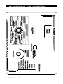
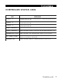
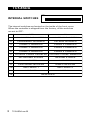
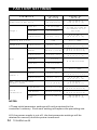
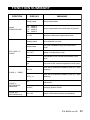
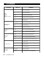
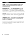
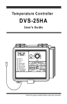
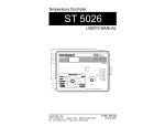
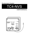
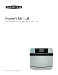
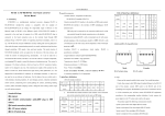
Temperature Controller TC5-8SDA USER'S MANUAL TABLE OF CONTENTS Page3 PRECAUTIONS ....................................................................... FEATURES ............................................................................. 4 LOCATION OF THE CONTROLS ................................................ 6 Controller Status Leds ........................................................... 7 Internal Switches ................................................................. 8 INSTALLATION ...................................................................... 9 Mounting Instructions ............................................................ 9 Connections ........................................................................ 9 Temperature Probes ........................................................... 10 Heating / Cooling Options ..................................................... 12 CHANGING THE PARAMETER SETTINGS ................................. 13 Using the Display ................................................................ 13 Locking the Parameter Settings ............................................ 14 TEMPERATURE SETTINGS ..................................................... 15 Temperature Units .............................................................. 15 Viewing Temperatures ........................................................ 15 Temperature Set Point ........................................................ 18 Temperature Curve............................................................. 19 MINIMUM VENTILATION CYCLE ............................................. 23 Principle of Operation .......................................................... 23 Ramping Option .................................................................. 24 Outside Temperature Compensation ...................................... 26 Minimum Ventilation Settings ............................................... 28 VENTILATION ...................................................................... 30 DEHUMIDIFICATION ............................................................. 34 MIST COOLING .................................................................... 37 HEATER SETTINGS ............................................................... 41 ALARM SETTINGS ................................................................ 46 TEST MODE ......................................................................... 48 TROUBLESHOOTING GUIDE ................................................... 49 TECHNICAL SPECIFICATIONS ................................................ 53 FACTORY SETTINGS............................................................. 54 FUNCTION SUMMARY .......................................................... 55 GLOSSARY ......................................................................... 57 2 TC5-8SDA.rev.02 PRECAUTIONS We strongly recommend installing supplementary natural ventilation as well as a back-up thermostat on at least one cooling stage (refer to the wiring diagram enclosed with this user's manual to connect the thermostat). Although fuses on the outputs of the controller protect its circuits in case of an overload or overvoltage, we recommend installing an additional protection device on the controller's supply circuit. The room temperature where the controller is located MUST ALWAYS REMAIN BETWEEN 32°F AND 104°F (0°C TO 40°C). To avoid exposing the controller to harmful gases or excessive humidity, it is preferable to install it in a corridor. DO NOT SPRAY WATER ON THE CONTROLLER FOR CUSTOMER USE Enter the serial number located on the side of the controller below for future reference. Model number: Serial number: TC5-8SDA TC5-8SDA.rev.02 3 FEATURES The TC5-8SDA is an electronic device used for environmental control in livestock buildings. It allows the user to maintain a specified target temperature by controlling the operation of ventilation and heating equipment. Six stages of constant-speed fans or mist units and two stages of either constant-speed fans or heaters can be connected to the controller. In addition, the last cooling stage can be configured as a mist stage. The main features of the TC5-8SDA are as follows: THREE-DIGIT DISPLAY A three-digit display provides a high level of accuracy, allowing the user to specify a temperature to within one tenth of a degree (in Fahrenheit or Celsius units). PILOT LIGHTS Pilot lights indicating the state of outputs allow the user to monitor the operation of the system without having to enter the building. MINIMUM VENTILATION CYCLE When ventilation is not required for cooling, the first stage fans can be operated either continuously or intermittently to reduce the level of humidity and supply oxygen to the room. RAMPING OPTION ON STAGE 1 The running time of the fans can be increased (or decreased) gradually to smooth out the transition between the minimum cycle and full operation of Stage 1 fans. MINIMUM VENTILATION COMPENSATION CURVE An outside probe can be connected to the controller to adjust the minimum ventilation cycle as a function of outside temperature. 4 TC5-8SDA.rev.02 TC5-8SDA TEMPERATURE CURVE The controller can be set to automatically change the temperature set point over a given period of time in accordance with the user's requirements by specifying a temperature curve with up to six different points. HUMIDITY COMPENSATION When the humidity level is high, an additional fan stage can be used to dehumidify the building. Mist units can also be turned off automatically when the humidity is too high. HIGH/LOW TEMPERATURE ALARM OUTPUT FOUR INDEPENDENT TEMPERATURE PROBE INPUTS Up to four temperature probes can be connected to the controller in order to obtain a more accurate reading of the average room temperature and a faster reaction time. OVERLOAD AND OVERVOLTAGE PROTECTION Fuses and other protection devices are installed on the outputs of the controller to protect its circuitry in the case of an overload or overvoltage. COMPUTER CONTROL The controller can be connected to a computer, thus making it possible to centralize the management of information and diversify control strategies. TEST MODE A test mode allows you to simulate temperature changes and verify controller performance. TC5-8SDA.rev.02 5 LOCATION OF THE CONTROLS 6 TC5-8SDA.rev.02 TC5-8SDA CONTROLLER STATUS LEDS LED ME AN IN G S TAGE S 1 - 2 F L A S H E S WH E N S TA G E 1 F A N S A R E O N . 2 FANS ARE ALSO ON. TU R N S O N WH E N S T A G E S TAGE S 3 - 4 F L A S H E S WH E N S TA G E 3 F A N S A R E O N . 4 FANS ARE ALSO ON. TU R N S O N WH E N S T A G E S TAGE S 5 - 6 F L A S H E S WH E N S TA G E 5 F A N S A R E O N . 6 FANS ARE ALSO ON. TU R N S O N WH E N S T A G E S TA GE 7 / H E AT E R 2 T U R N S O N WH E N S TA G E 7 F A N S A R E O N O R WH E N H E A T E R 2 IS ON. S TA GE 8 / H E AT E R 1 T U R N S O N WH E N S TA G E 8 F A N S A R E O N O R WH E N H E A T E R 1 IS ON. T E M P E R AT U R E C U R V E TU R N S O N WH E N TH E TE M P E R A TU R E C U R V E IS A C TIV A TE D . D E F. P R O B E / A L A R M TU R N S O N WH E N A N A L A R M IS D E T E C T E D . D E F E C TIV E P R O B E IS D E TE C TE D . F L A S HE S WHE N A C OMP E N S AT ION T U R N S O N W H E N H U M I D I T Y C O M P E N S A T I O N I S I N E F F E C T. TC5-8SDA.rev.02 7 TC5-8SDA INTERNAL SWITCHES ON 1 2 3 4 5 6 7 8 9 10 11 12 The internal switches are located on the inside of the front cover. When the controller is shipped from the factory, all the switches are set to OFF. # OFF ON 1 UNLOC K E D PA RA ME TE RS LOC K E D PA RA ME TE RS 2 FA HRE NHE IT D E GRE E S C E LS IUS D E GRE E S 3 P ROB E 2 D IS A B LE D P ROB E 2 E NA B LE D 4 P ROB E 3 D IS A B LE D P ROB E 3 E NA B LE D 5 P ROB E 4 D IS A B LE D P ROB E 4 E NA B LE D 6 OUTS ID E P ROB E D IS A B LE D OUTS ID E P ROB E E NA B LE D 7 NO HE ATING S TA GE S HE ATING S TA GE S 8 1 HE ATE R 2 HE ATE RS 9 C A S C A D ING HE ATE RS ZONE D HE ATE RS 10 MIS T MOD E 1 MIS T MOD E 2 11 MIS T OFF MIS T ON 12 8 TC5-8SDA.rev.02 RE S E RV E D INSTALLATION MOUNTING INSTRUCTIONS Open the latch and lift the cover. Remove the black caps located on each of the four mounting holes. Mount the enclosure on the wall using four screws. Be sure the electrical knockouts are at the bottom of the enclosure in order to prevent water from entering the controller. Insert the screws in the mounting holes and tighten. Fasten the four black caps provided with the controller onto the four mounting holes. The enclosure must be mounted in a location that will allow the cover to be completely opened right up against the wall. CONNECTIONS To connect the controller, refer to the wiring diagram enclosed with this user's manual. Set the voltage switch to the appropriate voltage. Use the electrical knockouts provided at the bottom of the enclosure. Do not make additional holes in the enclosure, particularly on the side of the enclosure when using a computer communications module. It may be necessary to install a transformer in order to supply the appropriate voltage to the heating unit. ALARM CONNECTION: There are two types of alarms on the market. One type activates when current is cut off at its input, whereas the other activates when current is supplied at its input. For an alarm of the first type, use the NO terminal as shown on the wiring diagram. For an alarm of the second type, use the NC terminal. ! WARNING ALL WIRING MUST BE DONE BY AN AUTHORIZED ELECTRICIAN AND MUST COMPLY WITH APPLICABLE CODES, LAWS AND REGULATIONS. BE SURE POWER IS OFF BEFORE DOING ANY WIRING TO AVOID ELECTRICAL SHOCKS AND EQUIPMENT DAMAGE. TC5-8SDA.rev.02 9 TC5-8SDA TEMPERATURE PROBES 1 Connecting the Probes The controller is supplied with one temperature probe connected to input # 1. Three additional room probes can be connected to inputs # 2, 3 and 4 and an outside probe can be connected to input # 5 (see wiring diagram enclosed). CAUTION: Probes operate at low voltage and are isolated from the supply. Be sure that probe cables remain insulated from all high voltage sources. In particular, do not route the probe cables through the same electrical knockout as other cables. Do not connect the shield from the probe cable to a terminal or a ground. Switches are used to activate or deactivate the additional probes connected to the controller. ON Activate each additional probe by setting the appropriate switch to ON: 3 4 5 Switch # 3 activates the probe connected to input # 2. Switch # 4 activates the probe connected to input # 3. Switch # 5 activates the probe connected to input # 4. 2 Extending the Probes Each probe can be extended up to 500 feet (150 meters). To extend a probe: Use a shielded cable of outside diameter between 0.245 and 0.260 in (6.22 and 6.60 mm) (the cable dimensions should not be under 18 AWG) to ensure the cable entry is liquid tight. Do not ground the shielding. 10 TC5-8SDA.rev.02 TC5-8SDA It is preferable to solder the cable joint to ensure a proper contact between the two cables. CAUTION: Do not run probe cables next to other power cables. When crossing over other cables, cross at 90°. 3 Installing the Outside Probe Run the outside probe cable on the north side of the building, 6 ft (2 m) below the eave, inside a pale colored conduit. Avoid installing the probe in direct sunlight or exposed to the rain. Be sure the probe cable is isolated from sheet metal or any other conductive material. Be sure no cable joint is exposed to air or water. 4 Defective Probes If a defective probe is detected, the Defective Probe Pilot Light flashes. The room temperature shown on the display is then the average temperature measured by the probes in working condition. The controller will operate according to this temperature. To identify the defective probe: Set the selection knob to ROOM TEMPERATURE . The room temperature is displayed. Press the push-button. If the probe connected to input # 1 and supplied with the controller is not defective, the letters"PR1" are displayed, alternating with the on/off state of the probe and the TC5-8SDA.rev.02 11 TC5-8SDA temperature measured by the probe. If the probe is defective, the letters "PR1" are displayed, alternating with the state of the probe and the letter "P". For each additional probe connected to the controller: Press the push-button once again. If the probe is not defective, the letters "PR#" (where # is the number of the input to which the probe is connected) are displayed, alternating with the on/off state of the probe and the temperature measured by the probe. If the probe is defective, the letters "PR#" are displayed, alternating with the on/off state of the probe and the letter "P". Outside Probe: If the outside probe is defective, the display shows the letter "P" when the parameter selection knob is set to OUTSIDE To. HEATING / COOLING OPTIONS Stages 7 and 8 can operate as heating or cooling stages. ð Set switches # 7 and # 8 to OFF to use both stages for cooling. ON ð Set switch # 7 to ON and switch # 8 to OFF to use Stage 8 for heating and Stage 7 for cooling. ð Set switches # 7 and # 8 to ON to use 7 8 both stages for heating. Note that if only one stage is used for heating, it must be Stage 8. 12 TC5-8SDA.rev.02 CHANGING THE PARAMETER SETTINGS USING THE DISPLAY Flashing Values: The display will flash in certain cases and not in others. The flashing indicates that the value shown can be adjusted. A value that is not flashing cannot be adjusted. 78.0 Relative and Absolute Values: Some parameter adjustments are displayed both as a relative value and an absolute temperature. This applies to all heating and cooling differentials, the mist differential and the mist and heater offset. The parameter is first displayed as a relative value. The corresponding absolute temperature is displayed after six seconds if no action is taken by the user. The absolute value is the temperature at which the stage turns on (except in the case of the heater and mist offsets where the value displayed is the temperature at which the stage turns off). If the user turns the adjustment knob, the relative value reappears. For example, when the user turns the selection knob to the differential position COOLING- DIFF 2-8, the sequence is as follows: (i) The current differential for stage 2 flashes on the display, alternating with "St .2". 2.0 St 2 (ii) If, after about 6 seconds, no action is taken by the user, the absolute temperature value is displayed, alternating with "St 2" and "Str". In this case, the absolute value is: Set Point + Stage 1 Differential + Stage 2 Differential. TC5-8SDA.rev.02 13 TC5-8SDA 78.0 St 2 Str (iii) When the user turns the adjustment knob to make an adjustment to the stage 2 differential, the relative value reappears on the display. 2.3 In the case of the mist and heating units, the starting temperature is displayed with the letters "STr" when adjusting the differential and the stopping temperature is displayed with the letters "STP" when adjusting the offset. LOCKING THE PARAMETER SETTINGS The parameter settings can be locked to prevent accidentally modifying them. When the settings are locked, only the temperature set point can be modified (as long as the temperature curve is deactivated). To lock the parameter settings: Set internal switch # 1 to ON. To unlock the parameter settings: Set internal switch # 1 to OFF. 14 TC5-8SDA.rev.02 TEMPERATURE SETTINGS TEMPERATURE UNITS Temperatures can be displayed in either Celsius or Fahrenheit units Set internal switch # 2 to the desired position: ON ON to display temperatures in Celsius units. OFF to display temperatures in Fahrenheit units. 2 VIEWING TEMPERATURES To display the desired temperature, set the selection knob to ROOM TEMPERATURE. The readout can display values from -40.0oF to 120.0oF ( -40.0oC to 48.9oC). 1 Viewing Room Temperature The room temperature is the average value of all temperatures measured by activated probes in proper operating condition. Set the selection knob to ROOM TEMPERATURE / PROBE To. The room temperature is displayed. 2 Viewing Probe Temperatures The controller can display probe temperatures individually. Probes can also be turned on or off to control the temperature in different parts of the building. Set selection knob to ROOM TEMPERATURE / PROBE TEMP. The average room temperature is displayed. TC5-8SDA.rev.02 15 TC5-8SDA Press the push-button. The temperature reading from probe 1 is displayed, alternating with the letters "Pr 1" and the on/off state of probe 1. For each additional probe, press the push-button. The temperature reading from probe x is displayed, alternating with the letters "Pr x" and the on/off state of the probe, etc. Note: The display returns to the average room temperature after one minute. 3 Viewing OutsideTemperature The outside temperature can be viewed only if a probe is connected to input # 5. Set the selection knob to OUTSIDE To. The outside temperature is displayed. If no outside probe is connected, "----" is displayed. 4 Viewing Minimum / Maximum Temperatures The minimum and maximum temperatures are the lowest and highest temperature values recorded since the last reset. Maximum and minimum temperatures values are recorded for the average room or outside temperature as well as for individual probe temperatures. Set the selection knob to ROOM TEMPERATURE / PROBE TEMP or OUTSIDE T°. The current room or outside temperature is displayed. Turn the adjustment knob clockwise by one notch. The minimum temperature flashes on the display, alternating with the letters "Lo". 16 TC5-8SDA.rev.02 TC5-8SDA Turn the adjustment knob clockwise one notch further. The maximum temperature flashes on the display, alternating with the letters "Hi". Turn the adjustment knob clockwise a third notch. The room temperature is displayed again. For each individual probe, press the push-button. The temperature reading from probe x is displayed, alternating with the letters "Pr x" and the on/off state of the probe. Turn the adjustment knob clockwise by one notch. The minimum temperature is displayed, alternating with the letters "Lo". Turn the adjustment knob clockwise one notch further. The maximum temperature is displayed, alternating with the letters "Hi". Turn the adjustment knob clockwise a third notch. The probe temperature is displayed again. Press the push-button to access the other probes, etc. NOTE: If you let the display flash for more than 10 seconds, the controller resets the minimum and maximum temperatures currently in memory (the display stops flashing to indicate that the reset has been done). TC5-8SDA.rev.02 17 TC5-8SDA TEMPERATURE SET POINT The temperature set point is the target room temperature. It can be adjusted between -40.0°F and 99.9°F (-40.0°C and 37.7°C). Adjusting Temperature Set Point Set the selection knob to SET POINT / T° CURVE.The current set point flashes on the display. Use the adjustment knob to adjust the set point to the desired value. NOTE: The temperature set point can be adjusted only if the temperature curve is deactivated (see following section). 18 TC5-8SDA.rev.02 TC5-8SDA TEMPERATURE CURVE The user can define a temperature curve to adjust the set point automatically over a given time period. ○ ○ ○ ○ ○ ○ ○ ○ ○ ○ ○ ○ ○ ○ ○ ○ ○ ○ ○ ○ ○ ○ ○ ○ ○ d35 d50 d70 ○ ○ d25 ○ ○ d4 ○ ○ ○ ○ ○ ○ ○ ○ ○ ○ ○ ○ To1 To2 To3 To4 To5 To6 ○ Temperature d80 Days A curve is defined using six points. Each point specifies a day number and a set point for that day. Once the points of the curve are defined, the curve must be activated. The controller will change the temperature set point every hour in a linear fashion between consecutive points of the curve. When the last point of the curve is reached, the temperature set point for that day is maintained until the curve is reactivated. NOTES : i) All six points of the curve must be specified. If six points are not needed, repeat the last temperature value for each unnecessary point. ii) Certain restrictions apply to reduce the risk of errors: - The highest possible day number is 99. - Decreasing day numbers are not allowed. - Increasing temperatures are not allowed. - The temperature variation cannot exceed 3°F (1.6°C) per day. TC5-8SDA.rev.02 19 TC5-8SDA 1 Specifying the Curve Set the selection knob to SET POINT / To CURVE. The current temperature set point flashes on the display. Press the push-button. The word OFF is displayed indicating that the termperature curve is deactivated. If this is not the case, see below to deactivate the curve. Repeat the following steps for each of the six points: Press the push-button once again. The day number is displayed, alternating with the word "day". Using the adjustment knob, set the day number to the desired value. Press the push-button once again. The current temperature set point is displayed, alternating with the word "set". Using the adjustment knob, adjust the set point to the desired value. Once the six points of the curve have been specified, activate the curve as explained below. NOTE: Make sure the temperature curve is deactivated before specifying new points (see below). 20 TC5-8SDA.rev.02 TC5-8SDA 2 Activating Temperature Curve If you have just finished specifying the points on the curve: Press the push-button once again. The word OFF flashes on the display. Turn the adjustment knob clockwise one notch. The word ON flashes on the display and the Temperature Curve Pilot Light turns on, indicating that the temperature curve is now activated. Set the selection knob to ROOM TEMPERATURE. If you have previously defined the points on the curve: Set the selection knob to SET POINT / To CURVE. The current value of the temperature set point flashes on the display. Press the push-button. The word OFF is displayed. Press the push-button to display the points of the curve currently defined until the word OFF appears (thirteen clicks). Turn the adjustment knob clockwise one notch. The word ON flashes on the display and the Temperature Curve Pilot Light turns on, indicating that the temperature curve is now activated. Set the selection knob to ROOM TEMPERATURE. TC5-8SDA.rev.02 21 TC5-8SDA 3 Viewing Current Set Point and Day Number When the temperature curve is activated, the current temperature set point and day number can be viewed at any time. The current day number can also be adjusted in order to move forward or backward on the temperature curve. Set the selection knob to SET POINT / To CURVE. The current temperature set point is displayed. Press the push-button. The current day number is displayed, alternating with the letters "cur. day". Use the adjustment knob to set the day number to the desired value. 4 Deactivating Temperature Curve Set the selection knob to SET POINT / To CURVE. The current temperature set point is displayed. Press the push-button to display the points of the curve actually defined until the word ON appears (fourteen clicks). Turn the adjustment knob counterclockwise one notch. The 22 TC5-8SDA.rev.02 MINIMUM VENTILATION CYCLE PRINCIPLE OF OPERATION When the room temperature is below the set point, the Stage 1 fans operate according to the minimum ventilation cycle. Running the fans even though ventilation is not required for a cooling purpose is useful to reduce humidity levels and supply oxygen to the room. It also prevents the fans from freezing in winter. TIME ON STAGE 1 STAGE 1 OFF TIME OFF STAGE 1 During time on, the Stage 1 fans run. The Stages 1-2 Pilot Light flashes. During time off, the Stage 1 fans do not run. The Stages 1-2 Pilot Light turns off. Minimum Ventilation Cycle Settings 1. To run the fans continuously at minimum speed, set time off to zero and time on to any value other than zero. 2. To stop the fans, set time on to zero and time off to any value. 3. To run the fans intermittently, set time on to the desired running time and time off to the desired off time. TC5-8SDA.rev.02 23 TC5-8SDA RAMPING OPTION The user has two options for controlling the transition from the minimum ventilation cycle to full operation of the Stage 1 fans, i.e. in the temperature interval between the set point and the set point + Stage 1 differential. In the first option (ramping), the running time of the fans is increased (or decreased) gradually to smooth out the transition between full operation of Stage 1 fans and the minimum cycle. In the second option, no transition is made from the minimum cycle to full operation of the Stage 1 fans. The running time of the fans is simply defined according to the minimum ventilation cycle. Option 1: With Ramping Running Time B C 0.3oF TIME ON = CYCLE TIME A TIME ON 1234567890123 1234567890123 1234567890123 1234567890123 1234567890123 1234567890123 1234567890123 1234567890123 Indoor Temperature DIFFERENTIAL 1 SET POINT STAGE 1 MINIMUM VENTILATION CYCLE This option is activated from the front panel. At room temperatures at or below the set point, the controller operates the Stage 1 fans according to the minimum ventilation cycle. If the room temperature rises above the set point, a new TIME ON is calculated periodically as the temperature increases to allow a smooth progres 24 TC5-8SDA.rev.02 TC5-8SDA sion (from point A to point B) up to full operation of the fans when the set point + differential 1 is reached*. If the room temperature decreases 0.3oF below the set point + differential 1, the TIME ON value of the minimum ventilation cycle decreases gradually from a value equal to the total cycle time (point C) to the value defined by the parameter settings (TIMER STAGE 1 TIME ON). Option 2: Without Ramping Running Time TIME ON = CYCLE TIME A TIME ON Indoor Temperature DIFFERENTIAL 1 SET POINT STAGE 1 MINIMUM VENTILATION CYCLE 1234567890123456789012345 1234567890123456789012345 1234567890123456789012345 1234567890123456789012345 1234567890123456789012345 1234567890123456789012345 1234567890123456789012345 1234567890123456789012345 1234567890123456789012345 This option is activated when ramping is turned off. When the temperature is less than the set point + differential 1, Stage 1 fans run according to the minimum cycle (see above). When the room temperature reaches point A, stage 1 fans run continuously with no transition. When the temperature decreases to the set point, Stage 1 fans start operating according to the minimum ventilation cycle. * When Time Off becomes less than 15 seconds, it is fixed at 15 seconds until the temperature has reached the set point + differential 1. At that point, the stage 1 fans operate continuously. TC5-8SDA.rev.02 25 TC5-8SDA OUTSIDE TEMPERATURE COMPENSATION The TC5-8SDA has the capability of automatically adjusting the running time of the minimum ventilation fans as a function of outside temperature. As the weather gets colder, the on time is decreased gradually to compensate for the change. This can help reduce costs by reducing the ventilation when it is not required. A curve is used to calculate the required compensation as a percentage of current on time (see following page). Only the running time is adjusted; the total cycle time remains unchanged. Note that internal switch # 6 must be set to ON for this feature to work. Examples of Ventilation Compensations Outdoor Temperature > 50 oF Compensation = 100% ON ○ OFF ○ ○ TIME ON ○ ○ ○ CYCLE TIME Outdoor Temperature = 25 oF Compensation = 66.5% ON OFF ○ TIME ON ○ ○ ○ ○ ○ CYCLE TIME In the first example given on the following page, compensation is not needed when the outside temperature is greater than 50 oF. The fans operate according to the full running time defined by the parameter settings. In the second example, the running time is decreased to 66.5% of full running time to compensate for the colder outdoor temperature. Cycle time remains unchanged. 26 TC5-8SDA.rev.02 TC5-8SDA FIGURE 2: COMPENSATION CURVE Minimum Ventilation Compensation 100 Ventilation Compensation (%) 90 80 70 60 50 40 30 20 10 0 -20 -15 -10 -5 0 6 10 15 20 25 30 36 40 45 50 70 Outside Temperature (F) NOTES: i) When the compensation factor is activated, the lowest time on value allowed after zero is 30 seconds. ii) The controller recalculates the compensation factor at the end of the time on portion of each timer cycle. TC5-8SDA.rev.02 27 TC5-8SDA MINIMUM VENTILATION SETTINGS 1 Adjusting Stage 1 Differential The Stage 1 cooling differential is the temperature difference between the moment the Stage 1 constant-speed fans start running continuously and the moment they return to minimum cycle operation (see the diagram above). The differential can be adjusted between 0.5°F and 20.0°F (0.3°C and 11.1°C). Set the selection knob to STAGE 1 DIFFERENTIAL/RAMPING. The current differential for Stage 1 flashes on the display. Use the adjustment knob to adjust the differential to the desired value. 2 Viewing and Adjusting Stage 1 Timer Settings Time on can be adjusted between 0 and 900 seconds, in increments of 15 seconds. Set the selection knob to STAGE 1 TIMER. The current time on for Stage 1 flashes on the display, alternating with the letters "On". If the ramping option has been enabled, the actual time on value may differ from the user-defined time on. When this is the case, the actual time on value is displayed, alternating with the letters "On" and "co". Use the adjustment knob to adjust time on to the desired value. Press the push-button. The current time off for Stage 1 flashes on the display, alternating with the letters "OFF". If the ramping option has been enabled, the actual time off value may differ from the user-defined time off. When this is the case, the actual time off value is displayed, alternating with the letters "OFF" and "co". 28 TC5-8SDA.rev.02 TC5-8SDA 3 Activating / Deactivating Ramping Option Set the selection knob to STAGE 1 DIFFERENTIAL/RAMPING. The current Stage 1 differential flashes on the display. Press the push-button. The on/off state of the ramping feature is displayed, i.e. ON / OFF. Use the adjustment knob to set the state to the desired value. 4 Activating / Deactivating Outside T° Compensation Set the selection knob to OUTSIDE To SETTINGS. The current outside temperature is displayed. If " " is displayed, internal switch # 6 (outside temperature probe) is set to off. Press the push-button. The status of the compensation factor is displayed, i.e. ON / OFF. Use the adjustment knob to set the status to the desired value. After ten seconds, the display returns to the outside temperature value. TC5-8SDA.rev.02 29 VENTILATION The TC5-8SDA controls six stages of constant-speed fans (Stage 1-6) and up to two optional stages of constant-speed fans (Stage 7-8). In this mode, all ventilation stages operate as normal ON/OFF stages as shown below: DIFF. 8 STAGE 8 30 TC5-8SDA.rev.02 STAGE 5 STAGE 4 STAGE 3 STAGE 2 STAGE 1 DIFF. 1 MINIMUM VENTILATION CYCLE SET POINT STAGE 1 STAGE 2 STAGE 3 STAGE 4 STAGE 5 STAGE 6 STAGE 7 12345678901234 12345678901234 12345678901234 12345678901234 12345678901234 12345678901234 12345678901234 12345678901234 12345678901234 12345678901234 12345678901234 12345678901234 12345678901234 12345678901234 12345678901234 12345678901234 12345678901234 12345678901234 12345678901234 12345678901234 DIFF. 2 DIFF. 3 DIFF. 4 DIFF. 5 DIFF. 6 STAGE 6 STAGE 8 Cooling VENTILATION OPERATION DIAGRAM DIFF. 7 STAGE 7 TC5-8SDA If the room temperature rises: When Room To < Set Point + Differential 1, the Stage 1 fans run according to the minimum ventilation cycle. When Room To = Set Point + Differential 1, the Stage 1 fans run continuously. When Room To = Set Point + Differential 1 + Differential 2, the Stage 2 fans start to run. A new cooling stage is turned on when the room temperature reaches the set point plus the sum of the differentials of the preceding stages plus the current stage differential. If the room temperature falls: When Room To = Set Point + Differentials 1 to 7, the Stage 8 fans return to a stop. When Room To = Set Point, the Stage 1 fans stop running continuously and start to run according to the minimum ventilation cycle. When the room temperature drops below this point, the stage 1 fans operate according to the minimum ventilation cycle. TC5-8SDA.rev.02 31 TC5-8SDA Adjusting Stage 2-8 Differentials The Stage 2-8 cooling differentials are the temperature differences between the moment the constant-speed fans start to run and the moment they turn off for each stage (see the diagram above). The differentials can be adjusted between 0.5°F and 20.0°F (0.3°C and 11.1°C). Set the selection knob to STAGE 2-8 DIFFERENTIALS. The current differential for Stage 2 is displayed, alternating with the letters «St. 2». Use the adjustment knob to adjust the differential to the desired value. Press the push-button. The current differential for Stage 3 flashes on the display, alternating with the letters "St 3". Use the adjustment knob to adjust the differential to the desired value. Press the push-button. The current differential for Stage 4 flashes on the display, alternating with the letters "St 4". Use the adjustment knob to adjust the differential to the desired value. Press the push-button. The current differential for Stage 5 flashes on the display, alternating with the letters "St 5". Use the adjustment knob to adjust the differential to the desired value. If Stage 6 is not a mist stage press the push-button. The current 32 TC5-8SDA.rev.02 TC5-8SDA differential for Stage 6 flashes on the display, alternating with the letters "St 6". Use the adjustment knob to adjust the differential to the desired value. If Stage 7 has not been configured for mist or heating, press the push-button. The current differential for Stage 7 flashes on the display, alternating with the letters "St 7". Use the adjustment knob to adjust the differential to the desired value. If Stage 8 has not been configured for mist or heating, press the push-button. The current differential for Stage 8 flashes on the display, alternating with the letters "St 8". Use the adjustment knob to adjust the differential to the desired value. TC5-8SDA.rev.02 33 DEHUMIDIFICATION Dehumidification uses a fan stage not currently needed for cooling to lower the humidity level when the relative humidity reaches the humidity set point. This feature is activated from the front panel. The diagram below illustrates how dehumidification works. Relative Humidity Stage 1 fans run continuously. Heaters operate normally. An additional ventilation stage is turned on if available. Humidity Set Point Normal operation Diff. 1 Temperature Set Point Temperature If HUMIDITY >= SET POINT: Case 1: If TEMPERATURE >= SET POINT + DIFFERENTIAL 1: The next available ventilation stage is turned on. Case 2: If TEMPERATURE < SET POINT + DIFFERENTIAL 1: Stage 1 fans run continuously. When the humidity drops below SET POINT: The controller resumes normal operation. 34 TC5-8SDA.rev.02 TC5-8SDA 1 Viewing Relative Humidity Set the selection knob to ROOM HUMIDITY - SETTINGS. The current relative humidity is displayed as a percentage. Turn the adjustment knob clockwise by one notch. The minimum humidity flashes on the display, alternating with the letters "Lo". Turn the adjustment knob clockwise one notch further. The maximum humidity flashes on the display, alternating with the letters "Hi". Turn the adjustment knob clockwise a third notch. The room humidity is displayed again. NOTE: If you let the display flash for more than 10 seconds, the controller resets the minimum and maximum humidity currently in memory (the display stops flashing to indicate that the reset has been done). 2 Adjusting Humidity Set Point The set point determines when dehumidification is activated. It can be adjusted from 40 to 100% relative humidity. Set the selection knob to ROOM HUMIDITY - SETTINGS. The current relative humidity is displayed as a percentage. Press the push-button. The humidity set point is displayed, alternating with the letters "SEt" and "rH". Use the adjustment knob to adjust the set point to the desired value. TC5-8SDA.rev.02 35 TC5-8SDA 3 Activating / Deactivating Dehumidification Set the selection knob to ROOM HUMIDITY - SETTINGS. The current relative humidity is displayed as a percentage. Press the push-button twice. The current on/off state of dehumidification is displayed. Use the adjustment knob to turn dehumidification on or off. 36 TC5-8SDA.rev.02 MIST COOLING The last ventilation stage can be configured as a mist cooling stage. The number of heating stages determines which stage this is. NUMBER OF HEATING STAGES 0 1 2 MIST STAGE 8 7 6 The other ventilation stages operate as explained above. To configure the controller to operate a mist stage, set internal switch # 11 to ON. The following diagram sums up the operation of the mist units. Mist units turn on in timer mode Mist units turn off Mist Diff. OFF Set Point Room Temperature Mist Offset The mist units operate according to a timer cycle. Time on is the running time of the mist units and time off is the off time of the mist units. TIME ON ON OFF TIME OFF TC5-8SDA.rev.02 37 TC5-8SDA Humidity Compensation on Mist Cooling Mist cooling can be turned off automatically if humidity levels are too high. There are two modes of operation: Mode I: In this mode, mist units are turned off if the relative humidity is greater than the humidity cut-off. To use this mode, set internal switch # 10 to OFF. Mode II: In this mode, mist units are turned off if the last ventilation stage is active and the relative humidity is greater than the humidity cut-off. To use this mode, set internal switch # 10 to ON. 1 Adjusting Mist Differential The mist differential is the variation in room temperature between the moment the mist units turn on and the moment they turn off.The differential can be adjusted between 0.5°F and 20.0°F (0.3°C and 11.1°C). Set the parameter selection knob to MIST TIMER/ OFFSET/DIFF/HUMIDITY CUTOFF. The current time on for the mist cycle is displayed, alternating with the letters "On". Press the push-button three times. The mist differential is displayed, alternating with the letters "dIF", Using the adjustment knob, set the differential to the desired value. 38 TC5-8SDA.rev.02 TC5-8SDA 2 Adjusting Mist Offset The mist offset is the temperature difference from the set point at which the mist units turn off. The offset can be adjusted between 0.5°F and 40.0°F (0.3°C and 22.2°C). Set the parameter selection knob to MIST TIMER/OFFSET/ DIFF/HUMIDITY CUT-OFF. The current time on for the mist cycle is displayed, alternating with the letters "On". Press the push-button twice. The mist offset is displayed, alternating with the letters "Oft". Using the adjustment knob, set the offset to the desired value. 3 Adjusting Mist Timer Settings Time on and time off can be adjusted between 0 and 60 minutes, in increments of 1 minute. To deactivate mist cooling, set time on to zero. Set the parameter selection knob to MIST TIMER/OFFSET/ DIFF/HUMIDITY CUT-OFF. The current time on for the mist cycle is displayed, alternating with the letters "On". Use the adjustment knob to set time on to the desired value (in minutes). Press the push-button. The current time off for the mist cycle is displayed, alternating with the letters "Off". Use the adjustment knob to set time off to the desired value (in minutes). TC5-8SDA.rev.02 39 TC5-8SDA 4 Viewing Relative Humidity Set the selection knob to ROOM HUMIDITY. The current relative humidity is displayed as a percentage. 5 Adjusting Humidity Cut-off In mode I, when the relative humidity exceeds the humidity cut-off value, the mist units stop operating. The humidity cut-off can be adjusted from 40 to 100%. Set the selection knob to MIST TIMER/OFFSET/DIFF/HUMIDITY CUT-OFF. The current time on for the mist cycle is displayed, alternating with the letters "On". Press the push-button four times. The relative humidity cut-off value is displayed, alternating with the letters "StP" and "rH". Use the adjustment knob to adjust the cut-off value to the desired value. 40 TC5-8SDA.rev.02 HEATER SETTINGS CASCADING HEATERS When cascading heating is used, the temperature used is the average room temperature (internal switch 9 is turned OFF). To use stages 7 and 8 for heating, set internal switches # 7 and 8 to ON. To use only stage 8 for heating, set internal switch # 7 to ON and # 8 to OFF. Heating Heater 2 ON Heater 2 Heater 2 OFF Heater 1 ON Heater 1 Heater 1 OFF HEATER 1 HEATER 2 DIFFERENTIAL DIFFERENTIAL HEATER 1 OFFSET Room Temperature Set Point If the room temperature rises: - at Set Point - Heater 1 Offset - Heater 1 Diff.: Heater 2 turns off. - at Set Point - Heater 1 Offset: Heater 1 turns off. If the room temperature falls: - at Set Point - Heater 1 Offset - Heater 1 Diff.: Heater 1 turns on. - at Set Point - Heater 1 Offset - Heater 1 Diff. - Heater 2 Diff.: Heater 2 turns on. TC5-8SDA.rev.02 41 TC5-8SDA ZONED HEATERS To configure your system for zoned heaters, set dipswitch # 9 to ON. Since the two heater outputs function independently, different probes are assigned to each output: Probes 1 and 2 are assigned to Heater 1 and Probes 3 and 4 are assigned to Heater 2. Individual probes can be turned on or off using the dipswitch settings. If both probes are activated for a given heater, the average temperature from both probes is used. To use stages 7 and 8 for heating, set internal switches # 7 and 8 to ON. To use only stage 8 for heating, set internal switch # 7 to ON and # 8 to OFF. Both heating zones can have negative and positive heater offsets. A negative offset is used when controlling heat mats, for example. To avoid ventilation problems when using zoned heating, a special protection is built into the device. Suppose the animals are young and confined to one part of the building (zone 1) while the rest of the building is heated at a minimum level (zone 2). If the temperature ZONE 2 PROBES 3 & 4 NOT USED MINIMUM HEAT ZONE 1 PROBES 1 & 2 YOUNG ANIMALS difference between zones is too great and zone 1 fans operate according to the average temperature for both zones, cooling in zone 1 may be insufficient. A built-in protection will operate the fans according to the probes of the zone with the highest temperature whenever the temperature difference between zones is greater than a user-defined value.. 42 TC5-8SDA.rev.02 TC5-8SDA The figure below explains the operation of zoned heaters. Heating Heater turns on ON Heater turns off OFF HEATER DIFFERENTIAL Temperature HEATER OFFSET Set Point If the room temperature rises: - at Set Point - Heater Offset 1 (Zone 1) : Heater 1 turns off. - at Set Point - Heater Offset 2 (Zone 2) : Heater 2 turns off. If the room temperature falls: - at Set Point - Heater Offset 1 - Diff. 1 (Zone 1) : Heater 1 turns on. - at Set Point - Heater Offset 2 - Diff. 2 (Zone 2) : Heater 2 turns on. TC5-8SDA.rev.02 43 TC5-8SDA 1 Adjusting Heater Offsets The heater offset can provide substantial energy savings if correctly adjusted according to the outside temperature. It is the number of degrees below the set point at which the heating units turn off (see diagram above). The heater 1 and 2 offsets can be adjusted between -10oF and 20.0oF (-5.6oC and 11.1oC). If the heater offset is negative, the heating units will turn off at temperatures above the set point. If cascading heating is used, only Heater 1 offset is used. Set selection knob to HEATER 1 OFFSET/DIFF. or HEATER 2 OFFSET/DIFF. The current heating offset is displayed, alternating with the letters "OFt". Use the adjustment knob to adjust the offset to the desired value. 2 Adjusting Heater Differentials The heating differential is the temperature difference between the moment the heater units turn on and the moment they turn off (see diagram above). The differential can be adjusted between 0.5oF and 20.0oF (0.3oC and 11.1oC). Set the selection knob to HEATER 1 OFFSET/DIFF. or HEATER 2 OFFSET/DIFF. The current heater offset is displayed, alternating with the letters "OFt". Press the push-button. The heater differential is displayed, alternating with the letters "diF". Use the adjustment knob to adjust the differential to the desired value. 44 TC5-8SDA.rev.02 TC5-8SDA 3 Adjusting Max. Temperature Difference Between Zones When using zoned heating, a built-in protection will operate the fans according to the probes of the zone with the highest temperature whenever the temperature difference between zones is greater than this parameter. The default value is 7.5°F (4.2°C) and values range from 5°F to 40.0°F (2.8°C to 22.2°C). Set the selection knob to HEATER 2 OFFSET/DIFF. The current heater offset is displayed, alternating with the letters "OFT". Press the push-button twice. The maximum temperature difference between zones is displayed, alternating with the letters "dif Zon". Use the adjustment knob to adjust the temperature difference to the desired value. TC5-8SDA.rev.02 45 ALARM SETTINGS The controller sets off an alarm in the case of a power failure, a fault in the supply circuit or a high or low temperature. Temperature alarms are defined according to the set point as shown in the diagram below. Room Temperature High Temperature Alarm High Alarm Offset Set Point Low Alarm Offset Time The situation changes for high temperature alarms, however, when the outside temperature is greater than the set point. In this case, the set point is replaced by the outside temperature as the reference point. This means an alarm is set off when the indoor temperature reaches Outside Temperature + High Alarm Offset. Internal switch # 6 must be set to ON to use this feature. A third parameter, called the critical high temperature, is defined to continue monitoring the indoor temperature for high temperatures. When the indoor temperature reaches the critical high temperature (defined as an absolute value), an alarm is set off. Adjusting the Alarm Settings The high and low alarm offsets range from 0.5oF to 40oF. The critical temperature ranges from -40.0°F to 99.9°F (-40.0°C to 37.7°C). Set the selection knob to ALARM OFFSETS / CRITICAL. The current low alarm offset flashes on the display, alternating with the word "LO". 46 TC5-8SDA.rev.02 TC5-8SDA Use the adjustment knob to set the low alarm offset to the desired value. Press the push-button. The current high alarm offset flashes on the display, alternating with the word "HI". Use the adjustment knob to set the high alarm offset to the desired value. Press the push-button. The current critical high temperature is displayed, alternating with the letters "Cri". Use the adjustment knob to set the critical high temperature to the desired value. TC5-8SDA.rev.02 47 TEST MODE A test mode allows you to simulate temperature changes and verify controller performance. In test mode, the temperature probe inputs are turned off, allowing the user to change the temperature used by the controller to operate the stages. The controller operates as before using the new temperature settings. Both the room temperature and the outside temperature can be adjusted in this way. To enter test mode: Turn the selector knob to the ROOM TEMPERATURE. The current room is displayed. Press and hold the push-button for 5 seconds. The letters "TST" are displayed, alternating with the room temperature. Turn the adjustment knob to adjust the room to the desired value. To adjust the outside temperature, turn the selector knob to OUTSIDE T°. The controller operates the stages according to the new temperature settings. To exit test mode: Turn the selector knob to the ROOM TEMPERATURE position. The current room is displayed. Press and hold the push-button for 5 seconds. NOTE: If no user activity is recorded after 5 minutes in test mode, the controller resumes normal operation. 48 TC5-8SDA.rev.02 TROUBLESHOOTING GUIDE PROBLEM CAUSE The display doesn't work. The circuit breaker on the service panel is off or tripped. Reset the circuit breaker. The wiring is incorrect. Fix the wiring. The input fuse is open. Replace the fuse. The voltage selector switch is in the wrong position. Set the switch to the correct position. The display board interconnect cable is unplugged from the power supply board. Plug the cable. The display shows the letter "P" Probe # 1 is improperly connected. Fix the probe's connection. The Defective Probe Pilot Light is on. One or more probes are defective. Follow the procedure described in DEFECTIVE PROBES to identify and replace the defective probe. The display shows sudden variations in the room temperature. A variation in resistance is induced on a probe. Make sure the probes are dry and move them away from drafts and sources of radiant heating. There is electrical noise near an extended probe cable. Do not run probe cables next to other power cables. When crossing other power cables, cross at 90o. SOLUTION TC5-8SDA.rev.02 49 TC5-8SDA PROBLEM Stage 1 fans are not running. Stage 1 fans run continuously at full speed. 50 CAUSE SOLUTION The wiring is incorrect. Correct the wiring. In particular, make sure two different lines are connected to each motor: line L1 modulated by the controller should be combined with another line (N for 115V or L2 for 230V) to activate the motor. Also, be sure the Stage 1 COMMON is supplied by line L1. The Stage's fuse is open. Replace the fuse. The display board interconnect cable is not plugged into the power supply board properly. Make sure the cable is firmly plugged in with the tabs in place. The fan motor is defective. Check if motor is defective by connecting it to an alternate power supply. Replace the motor if it still doesn't operate. The wiring is incorrect. Fix the wiring. The ambient temperature is above the set point. Adjust the set point to the desired value. TC5-8SDA.rev.02 TC5-8SDA PROBLEM CAUSE Stage 1 fans run erratically. The differential is too small. Adjust the differential to a higher value. The time on or time off is too short. Adjust the time on or time off to a higher value. Stage 1 fans do Time off is set to zero. not stop running when the controller is operating in The wiring is incorrect. minimum ventilation cycle. SOLUTION Set time off to a value other than zero. Correct the wiring. In particular, make sure two different lines are connected to each motor: line L1 modulated by the controller should be combined with another line (N for 115V or L2 for 230V) to activate the motor. Also, be sure the stage 1 COMMON is supplied by line L1. TC5-8SDA.rev.02 51 TC5-8SDA PROBLEME One of the other stages is not operating. 52 CAUSE SOLUTION The Stage's fuse is open. Replace the fuse. The display board interconnect cable is not plugged into the power supply board properly. Make sure the cable is firmly plugged in with the tabs in place. The wiring is incorrect. Correct the wiring. In particular, make sure two different lines are connected to each motor: line L1 modulated by the controller should be combined with another line (N for 115V or L2 for 230V) to activate the motor or heating unit. Also, make sure the Stage COMMON is supplied by line L1. The fan motor or heating unit is defective. Verify if the motor or heating unit is defective by connecting it to an alternate power supply. Replace the motor or heating unit If it still is not operating. The controller is defective. Listen to see if there is a clicking sound when the Stage's pilot light turns on. If there is no clicking sound, contact your distributor to repair the controller. TC5-8SDA.rev.02 TECHNICAL SPECIFICATIONS Supply: - 115/230 VAC (-18%, +8%),50/ 60 Hz, overload and overvoltage protection fuse F10-1A fast blow. - 12 VDC for AC back-up supply; can activate stages 1-8 if supplied with DC back-up voltage. Stage 1: ON-OFF output, 115/230 VAC, 50/60 Hz, 30VDC, 6A FAN,10A RES, fuse F1-10A slow blow. Stage 2: ON-OFF output, 115/230 VAC, 50/60 Hz, 30VDC, 6A FAN,10A RES, fuse F2-10A slow blow. Stage 3: ON-OFF output, 115/230 VAC, 50/60 Hz, 30VDC, 6A FAN,10A RES, fuse F3-10A slow blow. Stage 4: ON-OFF output, 115/230 VAC, 50/60 Hz, 30VDC, 6A FAN,10A RES, fuse F4-10A slow blow. Stage 5: ON-OFF output, 115/230 VAC, 50/60 Hz, 30VDC, 6A FAN,10A RES, fuse F5-10A slow blow. Stage 6: ON-OFF output, 115/230 VAC, 50/60 Hz, 30VDC, 6A FAN,10A RES, fuse F6-10A slow blow. Stage 7: ON-OFF output, 115/230 VAC, 50/60 Hz, 30VDC, 6A FAN,10A RES, heating or cooling, fuse F7-10A slow blow. Stage 8: ON-OFF output, 115/230 VAC, 50/60 Hz, 30VDC, 6A FAN,10A RES, heating or cooling, fuse F8-10A slow blow. Alarm: ON-OFF output, 115/230 VAC, 50/60 Hz, 30VDC, 3A , fuse F9-3A slow blow. Probes: Low voltage ( < 5V), isolated from the supply. Operating range: -40.0° to 120.0°F (-40.0° to 48.9°C). Accuracy: 1.8oF (1oC) between 41o and 95oF (5o and 35oC). Enclosure: ABS, moisture and dust-tight. The room temperature where the controller is located MUST ALWAYS REMAIN BETWEEN 32o AND 104oF (0o AND 40oC). TC5-8SDA.rev.02 53 FACTORY SETTINGS F A C T O R Y S E T T I N G P A R A M E T E R Te m p e r a t u r e Sta g e 1 S e t Sta g e S e t 2 -8 Ti me On 1 5 Ti me Off 0 s e c o nd s s e c o nd s 2 oF ( 1 . 1 oC ) P o i nt 0 D i ffe re nti a l 1 4 .0 °F D i ffe re nti a l Ti me On Ti me Off 2 oF ( 1 . 1 oC ) (7 .8 °C ) 2 . 0 oF ( 1 . 1 oC ) 1 Humi d i ty o ff He a te r o o F C ) 4 0 to 1 0 0 % 0 . 5 t o 2 0 oF ( 0 . 3 t o 1 1 . 1 oC ) 0 .5 °F (0 .3 °C to to 4 0 .0 °F 2 2 .2 °C ) 0 . 5 t o 2 0 oF ( 0 . 3 t o 1 1 . 1 oC ) mi nute to 6 0 4 0 to mi nute s mi nute s C ut- 9 5 % 1 0 0 % Offs e t 2 oF ( 1 . 1 oC ) - 1 0 t o 2 0 oF ( - 5 . 6 t o 1 1 . 1 oC ) D i ffe re nti a l 2 oF ( 1 . 1 oC ) 0 . 5 t o 2 0 oF ( 0 . 3 t o 1 1 . 1 oC ) 1 M a x . Te m p . D i f f e r e n c e B e twe e n Zo ne s Hi g h A la rm P a ra me te rs 9 9 .9 3 7 .7 0 . 5 t o 2 0 oF ( 0 . 3 t o 1 1 . 1 oC ) 0 1 0 to to to 9 0 0 s e c o nd s b y i nc re me nts o f 1 5 s e c o nd s 6 5 % Offs e t Mi s t -4 0 (-4 0 7 5 oF ( 2 3 . 9 oC ) P o i nt D i ffe re nti a l Humi d i ty R A N G E O F V A L U E S L o w 7 .5 °F Offs e t Offs e t C ri ti c a l Te m p . (4 .2 °C ) 5 (2 .8 to to 4 0 °F 2 2 .2 °C ) 1 2 .0 °F (6 .7 °C ) 0 .5 °F (0 .3 °C to to 4 0 .0 °F 2 2 .2 °C ) 1 0 .0 °F (5 .6 °C ) 0 .5 °F (0 .3 °C to to 4 0 .0 °F 2 2 .2 °C ) 9 5 .0 °F (3 5 °C ) -4 0 (-4 0 to to 9 9 .9 3 7 .7 o o F C ) NOTES: i) These initial parameter settings will not be retained in the controller's memory. Each new setting will replace the preceding one. ii) If the power supply is cut off, the last parameter settings will be retained in memory until the power is restored. 54 TC5-8SDA.rev.02 FUNCTION SUMMARY POSITION ROOM TEMPERATURE SET POINT / T° C URVE D ISPLAY steady value Room temperature Pr1 Pr2 Pr3 Pr4 Room temperature and on/off state for probe x - On/OFF - On/OFF - On/OFF - On/OFF Lo / Hi Mi ni mum / Maxi mum temperature value. flashi ng value User-adjusted set poi nt. steady value Set poi nt calculated usi ng the temperature curve. On / OFF Status of temperature curve. dAY D ay number of the current temperature curve poi nt. se t Set poi nt of the current temperature curve poi nt. On / co Ti me On for mi ni mum venti lati on cycle (co - wi th rampi ng) OFF / co Ti me Off for mi ni mum venti lati on cycle (co - wi th rampi ng) STAGE 1 - TIMER STAGE 1 D IFFERENTIAL /RAMPING STAGE 2-8 D IFFERENTIALS MEAN IN G di F D i fferenti al On/OFF Rampi ng Opti on On/Off St.x / Str Stage x di fferenti al (starti ng temperature) TC5-8SDA.rev.02 55 TC5-8SDA POSITION MIST TIMER/ OFFSET/ D IFF./ HUMID ITY C UT-OFF ROOM HUMID ITY SETTINGS HEATER 1OFFSET/ D IFF. HEATER 2 OFFSET/ D IFF. ALARM OFFSETS OUTSID E T° SETTINGS 56 D ISPLAY MEAN IN G On Ti me on for mi st cycle. Off Ti me off for mi st cycle. Oft / StP Mi st offset (stop temperature). di F / Str Mi st di fferenti al (start temperature). StP rH Humi di ty cut-off Steady value Relati ve humi di ty readi ng. SEt rH Humi di ty Set Poi nt On/OFF Humi di ty C ompensati on Oft / StP Heater 1 offset (stop temperature). di F / Str Heater 1 di fferenti al (start temperature). Oft / StP Heater 2 offset (stop temperature). di F / Str Heater 2 di fferenti al (start temperature). di F Zon Max. Temperature D i fference Between Zones Lo Low alarm offset. Hi Hi gh alarm offset. C ri . C ri ti cal temperature. Steady value Outsi de temperature ON / OFF On / off state of mi n. vent. compensati on TC5-8SDA.rev.02 GLOSSARY BANDWIDTH: The temperature interval within which the variable-speed fans of a given stage increase or decrease in speed proportionally to the temperature. CASCADING HEATERS: Heaters operate in a sequence. As the average room temperature drops, additional heaters are turned on as needed. CURTAIN DEAD BAND: The dead band is the temperature difference between the opening and closing temperatures of the curtains. Within this interval, the curtains are at rest. DEFAULT VALUE: A typical parameter setting defined at the factory. DIFFERENTIAL: The differential is the temperature difference between the moment the constant-speed fans or heating units of a given stage start running and the moment they return to a stop. HYSTERESIS: A hysteresis is used to smooth the transition from one state to another. For example, when the temperature drops to the cutoff point for a stage of constant-speed fans, the fans will actually be cut off at slightly less than the cut-off point. This way, if the temperature fluctuates around the cut-off point without dropping significantly below it, the controller will not oscillate between two states. For example, if the hysteresis is 0.3°F and the stage 2 fans are programmed to be cut off at 75°F, the cut-off will actually occur at 74.7°F. MINIMUM VENTILATION CYCLE: When the room temperature is below the set point, the Stage 1 fans operate intermittently to provide minimum ventilation to the room. MINIMUM VENTILATION SPEED CURVE: When Stage 1 operates variable-speed fans, they will run at minimum speed during the minimum ventilation cycle. The user can define a minimum ventilation speed curve to adjust the Stage 1 minimum speed automatically over a given time period. The minimum speed increases over time as the animals grow. TC5-8SDA.rev.02 57 TC5-8SDA OFFSET: An offset is a temperature difference from the set point that normally defines a cut-off point for a stage operation. For example, a heater offset of 2°F means the heaters will turn off at 2°F below the set point. RAMPING ON STAGE 1: When the temperature rises to the point where Stage 1 constant-speed fans are needed for cooling, the running time of the fans is increased gradually from the minimum ventilation settings up to full operation. Likewise, when the temperature drops below the set point, the running time is decreased gradually until the minimum ventilation settings are reached. SET POINT: The set point is the target room temperature. When the temperature is above the set point, the controller cools the room by turning on the cooling fans. When the temperature is below the set point, the controller heats the room by turning on the heaters. TEMPERATURE CURVE: The controller can be set to automatically change the temperature set point over a given period of time in accordance with the user's requirements. The set point decreases over time as the animals grow. ZONED HEATERS: When zoned heaters are used, heaters in each zone operate according to their own probes rather than the average temperature for the entire room. In this way, heaters across zones are independent of one another. 58 TC5-8SDA.rev.02