1
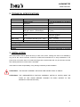
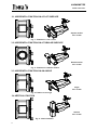
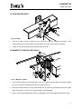
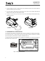
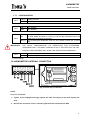
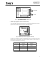
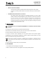
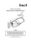
USER’S MANUAL
ANEMOMETER
VA000906
ITOWA
IT IS FORBIDDEN TO FULLY OR PARTIALLY REPRODUCE THIS MANUAL, WITHOUT
THE PRIOR WRITTEN AUTHORISATION FROM ITOWA.
IN THE EVENT OF INFRINGEMENT, ITOWA RESERVES THE RIGHT TO TAKE THE
ACTION IT DEEMS NECESSARY, IN ACCORDANCE WITH CURRENT LAW.
ITOWA RESERVES THE RIGHT TO MODIFY THIS MANUAL WITHOUT PRIOR
NOTIFICATION
MAANM2GB – Rev.1 – 22/06/2012
Approved by Engineering Manager: I. Martínez
ANEMOMETER
USER’S MANUAL
1. INTRODUCTION
The Itowa’s Anemometer has been designed to fulfil the requirements of the spanish law ITC "MIEAEM-2" of the Reglamento de aparatos de elevación y manutención1, for tower cranes and other lifting
aplications in construction sites.
The anemometer measures the wind speed and shows two different types of alert, through visual and
acoustic signals. One of them is the Warning signal, that is intermittent for more than 5 seconds and
it’s activated when the wind speed surpasses the 50 Km/h (31 mph) limit but not the 70 Km/h (43,5
mph) limit, and the other is the Alarm signal, that is continuous and warns that the wind speed is faster
than the 70 Km/h (43,5 mph) limit for at least 2 seconds (when it exceeds or when it decreases this
limit), alerting the danger. By this way, the anemometer filters any possible false warning produced by
wind gusts.
It offers different solutions for installation, from the comfort of the magnetic fixation to the versatility of
the quick fixing system that adapts on any vertical or horizontal surface, no matter being flat, tubular or
angle.
The high quality of the materials and components guarantees the highest visual and acoustic power,
and a great toughness and reliability, supporting electrical shutdowns for 15 seconds.
Its advanced and functional design makes possible an easy, quick and safe installation, thanks to a
simple connection cover.
Optionally allows:
•
2 outputs per relay (Warning and Alarm).
•
Metallic sensor or metallic warmed sensor.
•
RS485 output (for connection of external devices).
•
Adjusting the speed triggering system (below the predetermined limits of Warning and
Alarm).
•
1
1
Magnetic fixation.
Regulation of elevation and maintenance devices.
ANEMOMETER
USER’S MANUAL
2. TECHNICAL SPECIFICATIONS
Sensor
Horn
Lights
Power entry
Connection
Measurement system:
Measure range:
Resolution:
Dimensions:
Bitone
Amber light “Warning” (triang. shape)
Red light “Alarm” (round shape)
Frequency:
Power:
48, 115, 230 or 400 Vac (+10 / -15%)
Through 2 PG9 cablegands
Working temperature
Protection degree:
Dimensions with standard fixation:
Fixation
Optical
0 – 30 m/s (0-108 km/h (0 - 67 mph))
0,06 m/s
85 x 120 x 120 mm
110 dB
High luminescent diodes (100 milions
of cycles)
1 Hz flashes (60/min)
Amber (55 candles)
Red (98 candles)
10 VA (1A fuse)
Closing margin (∅ 5 ÷ 10 mm)
-20 to +60 ºC (-4 to 140ºF)
IP 65
306 x 226 x 170 mm
Bichromium-plated steel (4 mm.plate)
3. INSTALLATION
The anemometer must be placed at the top of the crane, alone, making sure that is not shielded by
any part of the crane’s structure, and that is visible and accessible for an easy maintenance. The
power entry connection has to be made ensuring that the anemometer will only be off when the wind
free slewing manoeuvre of the crane is activated.
Itowa does not claim responsability of any damage caused by a bad installation.
ATTENTION!: THE SUPORT ASSEMBLY SHOULDN’T BE HIGHER THAN 15º ANGLE.
ATTENTION!: THE ANEMOMETER’S FIXATION ASSEMBLY (METALLIC PARTS) MUST BE
FIXED AT THE CRANE BEFORE HANGING ITS BODY (EXCEPT IN THE
MAGNETIC FIXATION OPTION)
2
ANEMOMETER
USER’S MANUAL
3.1. HORIZONTAL FIXATION ON A FLAT SURFACE
Square section
min. 30 mm
VA000908
Fig. 1 : Fixation on a flat surface
3.2. HORIZONTAL FIXATION ON A TUBULAR SURFACE
Round section
min. 30 mm
VA000910
Fig. 2 : Fixation on a tubular surface
3.3. HORIZONTAL FIXATION ON AN ANGLE
Angle
min. 30 mm
Fig. 3. Fixation on an angle
3.4. VERTICAL FIXATION
Section
min. 30 mm
VA000914
Fig. 4 : Vertical fixation
3
ANEMOMETER
USER’S MANUAL
3.5. FIXATION PROCESS
3
2
1
Fig. 5: Fixation
1.
Once the fixation group is placed at the crane (1), insert the subjection brackets of the
anemometer (2) in the square holes of the fixation and anchor it with a down movement.
2.
Finally, fix the anemometer with the DIN 6921 M6 screw (3).
3.6. MAGNETIC FIXATION (OPTIONAL)
5
4
2
6
3
1
Fig. 6 : Magnetic fixation
1.
In the magnetic fixation, put the DIN 6921 screw (1), together with the M6 nut (3) without tighten
them up, through the passing hole (6) of the metallic fixation (2).
2.
Mount the metallic fixation (2) in the anemometer’s body, placing its 3 brackets inside the 3 square
holes of the fixation, so the screw (1) gets placed in its final position.
3.
Finally, put the other M6 DIN 6921 screw (4) and tighten up all with the M6 self-retaining nut (3).
4
ANEMOMETER
USER’S MANUAL
4.
All three magnets must be in contact with the crane subjection surface, that must be totally flat
and with a thickness of 6-8 mm minimum.
5.
For more security, after placing the anemometer at the crane, put the safety clamp (5), that
NEVER must be used as the unique fixation system.
6.
To take it out of the crane, you must move it from side to side holding the anemometer’s body,
NEVER by the vane.
CORRECT
INCORRECT
3.7. ANEMOMETER’S CONFIGURATION
The equipment allows different configuration types, through a minidip with 4 selectors placed within,
as an auto-test function, a restart function when the Alarm signal (70 Km/h) is activated or to disable
the acoustic signal in special areas as hospitals, residential zones, etc,...
To access the interior of the equipment, for changing the configuration or to connect it, just take out
the screws of the connection cover.
Mini-dip
ON
1 2 3 4
Fig. 7 : Configuration mini-dip
5
ANEMOMETER
USER’S MANUAL
3.7.1. CONFIGURATION
DIP1
DIP2
ON (1)
Starting auto-test
OFF
No starting auto-test
ON (1)
Horn enabled
OFF
Horn disabled
ON
DIP3
OFF(1)
IMPORTANT:
THE
Once passed the 70 Km/h limit, the ALARM signal remains activated, although
the wind speed decrease to 0 Km/h (it only will get deactivated when the
power is off for at least 15 seconds).
The ALARM signal disappears when the wind speed is below the 70 Km/h
limit.
DIP4’S
CONFIGURATION
IT’S
RESTRICTED
FOR
AUTHORIZED
PERSONNEL ONLY. ITS RIGHT POSITION IS ON, IF THE DIP4 IS IN THE OFF
POSITION THE EQUIPMENT WILL SHOW THE SENSOR ERROR MESSAGE.
DIP4
ON (1)
Normal function position
OFF
Maintenance position
(1) Initial settings.
3.8. ANEMOMETER’S INTERNAL CONNECTION
ON
1 2 3 4
Fuse (1A)
Fig. 8: Power entry connection
NOTE:
Once it’s connected:
1. Tighten up the cablegand strongly against the cable for keeping it safe from liquids and
dust.
2. Be sure the connection cover is closed to guarantee the total protection IP65.
6
ANEMOMETER
USER’S MANUAL
4. OPERATION
• AUTO-TEST
When it starts, the anemometer (config. DIP1) makes an auto-test, blinking every led and acoustic
signal (config. DIP2) with 2 pulses.
If you have installed a Speed limit pre-selection module, see the specific section below.
• ERROR SENSOR DETECTION
When a failure in the sensor is produced, a broken cable is detected or there is a wrong connection
(external sensor models), all the leds of the anemometer blink alternatively, not stopping until the
damage is fixed.
5. OPTIONAL
•
MODULES
o
2 Outputs per relay module (Warning & Alarm)
This module (fig. 9) has 2 commuted relays (125 Vac 0,6A), potential free, that only
get activated when the wind speed surpasses the WARNING and ALARM limits.
The WARNING relay keeps activated continuously, while the leds blink, until the wind
speed decreases under the established limit.
o
Speed limit pre-selection module
This module (fig.9) allows you to customize the triggering limits of the different signals
in high risk areas (this adjustments will always be under the WARNING and ALARM
limits established by the ITC “MIE-AEM-2”, otherwise the adjustments won’t work and
the equipment will return to the initial settings).
If the selected configuration is different from the standard, in the auto-test function, the
leds will blink 3 times instead 2.
The adjustments will only be effective after restarting the equipment.
7
ANEMOMETER
USER’S MANUAL
DEC UNI
56
56
56
WARNING
AVISO
234
234
56
234
789
01
01
789
789
01
01
789
234
ALARMA
ALARM
VA000919
Fig. 9 : Two outputs relay and Speed limit
pre-selection module
o
RS485 output (peripheric devices communication)
This module (fig.10) gives a RS485 output for connecting the different types of Itowa’s
peripheric devices like the Events recorder or the Display device.
1
2
3
4
5
A B
RS485
VA000920
Fig. 10. RS485 output module (peripheric devices)
It allows too to install an external and independent sensor at a maximum 20 meters
distance from the anemometer’s body (only in specific models). In these cases, you
must follow the table below for connecting:
(RS485 Module)
CIRCUIT Ner
STANDARD
SENSOR
WARMED
SENSOR
1
White
Black
2
Brown
Brown
3
Green
Yellow (Ground)
4
-
-
5
-
Blue
8
ANEMOMETER
USER’S MANUAL
•
METALLIC SHOVELS SENSOR
These shovels are made in injected aluminium alloy that gives the vane a higher
toughness and makes possible, thanks to its thermal conductivity, the warmed sensor
model.
•
WARMED SENSOR WITH METALLIC SHOVELS
The warmed sensor highly improves the equipment allowing it to work on hard
weather conditions with low temperature, when usually the ice, that can be formed in
the sensor, blocks the vane’s rotation, disabling the equipment and consequently the
security for the machine to work. This system incorporates a thermal resistor that
increases progressively the temperature to the level needed for melting the frost that
could have been made inside the vane.
6. RECYCLING
INFORMATION FOR THE PROPER MANAGEMENT OF ELECTRIC AND ELECTRONIC
DEVICES
The equipment’s refuses should never be mixed with general refuses.
These refuses can be delivered, without any extra cost, to the centers of refuse collection.
For further information, please contact your local authorities.
To recycle an electronic device separately from the general refuses avoids possible negative
consequences for the environment. Furthermore, it allows a proper recycling process for all the
pieces. This implies both energy and resources saving.
This symbol is marked in all products. It highlights both the obligation to collaborate with the
refuse collection and the warning of not using traditional containers for the elimination of the
products.
For further information, please contact your local authorities.
6.1. PACKAGING
→ The materials used for packaging are recyclable.
→ Please, consider the local norms with regards to the recycling of these products.
9