1
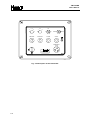
OPERATOR’S MANUAL
TINY-BLIND
TINY-BLIND
USER’S MANUAL
ITOWA S.A.U.
ANY REPRODUCTION, EITHER COMPLETE OR IN PART, OF THIS MANUAL IS
STRICTLY PROHIBITED UNLESS ITOWA HAS GIVEN ITS WRITTEN CONSENT
OTHERWISE, ITOWA RESERVES THE RIGHT TO INITIATE ALL APPROPRIATE ACTIONS
AS ESTABLISHED IN LAW
ITOWA RESERVES THE RIGHT TO MODIFY THIS MANUAL WITHOUT PRIOR ADVICE
MATCGB. DOC
27-09 - 00
SLS
TINY BLIND
USER´S MANUAL
INDEX
1. INTRODUCTION
1-1
2. DESCRIPTION OF THE RADIO-CONTROLLED EQUIPMENT
2-1
2.1. TRANSMITTER
3. TECHNICAL DATA
2-1
3-1
3.1. OVERALL DATA OF THE SYSTEM
3-1
3.2. TRANSMITTER
3-1
4. START-UP AND OPERATION
4-1
5. TRANSMITTER MAINTENANCE
5-1
6. TROUBLESHOOTING
6-1
ANNEX
A. ADDRESS
A-1
TINY BLIND
USER´S MANUAL
1. INTRODUCTION
The present manual is a guide for the proper operation of the multi-frequency remote control family from
ITOWA.
This equipment has been especially designed for the wireless remote control of any machines
incorporating electromechanical drives.
Radio-transmitted control signals are transmitted using frequency modulation (FM) and FFSK keying.
The most advanced technology and latest-generation microprocessors have been used in the electronic
design, providing total safety for radio-control yet operation.
To prevent incorrect operations from being executed, the system is equipped with several safety devices
that are described in next chapters. When any abnormalities are self-detected, the system locks any
controls operation that is commanded.
The system operates in the UHF frequency band, as required by the I-ETS 300 220 telecommunications
standard, having obtained the type approvals and national standards in the following countries:
SPAIN
UK
EIRE
FRANCE
GERMANY
FINLAND
ICELAND
BELGIUM
HOLLAND
PORTUGAL
SWEDEN
E 08 98 0076
13397
13988
TRA 24/5/124
Nº 98 0169 PPL 0
D800517K
FI98080090
IS-3025-00
IS-3024-00
RTT/TI/X84
CEPT LPD NL
ICP-011TC-99
Ue970144
For other approvals, please check with ITOWA.
1-1
TINY BLIND
USER´S MANUAL
2. DESCRIPTION OF THE RADIO-CONTROLLED EQUIPMENT
Remote control units of the TINY-BLIND family consist of the following items:
1.
TINY-BLIND TRANSMITTER
2.
RECEIVER
This manual only describes transmitter.
2.1. TRANSMITTER
This is a waterproof pushbutton box (with an IP 56 degree of protection) made of high-strength plastic.
This box has an input power supply (220Vac or 48 Vac).
Commands from the joysticks are fed into the microprocessor-based system, which takes care of
generating the FFSK signal, adding the directional and control codes to it, and injecting the signal to the
HF transmitter. The transmitter incorporates this command signal to its carrier frequency, which after
being filtered, will be sent by the antenna.
As shown in the block diagram (Fig. 2.1), the transmitter pushbutton box can be divided into three
sections: pushbutton section, control circuit section and HF transmitter section.
PUSHBUTTONS
SWITCHES
CONTROL
ELEMENTS
MODULATOR
TRANSMITTER
Fig. 2.1 Pushbutton box block diagram
(Fig. 2.2) reproduces a detailed overview of the operating and control elements:
2-1
TINY BLIND
USER´S MANUAL
1
4
5
8 7
1/2
2 3
2 3
1
0
4
0
0
1
START
STOP
6
RELEASE
AUXILIARY
ALARM
START
EMERGENCY
STOP
TRANSMITTER 1
VA000565
Fig. 2.2 Description of the transmitter
2-2
TINY BLIND
USER´S MANUAL
3. TECHNICAL DATA
3.1. OVERALL DATA OF THE SYSTEM
Manufacturer
INVESTIGATION TOTAL WARE S.A.U.
Model
TINY-BLIND
Type
Multi-frequency
Frequency
ISM-BAND
Number of commands
To 32 orders
Possibility of incorrect operation
1·10
Hamming distance
=6
Programmable codes
16777216
Command response time
<50 ms
Active emergency time
<50 ms
Passive emergency time
1900 ms
Operating range
< 90 meters
*
-18
3.2. TRANSMITTER
Frequency band:
UHF 433.050 to 434.750 MHz
Channel spacing:
25 kHz
Modulation:
FM
Transmitting power:
10 mW A.R.P.
Keying:
FFSK
Frequency stability:
± 2.5 ppm (from -30ºC to 70ºC)
Harmonics damping:
> 70 dB
Transmitting power consumption:
110 mA
Standby power consumption:
10 mA.
Power supply:
220 Vac or 48 Vac
Temperature range:
from -10ºC to +55 C
Material:
Polyamide
o
Approximate weight:
Dimensions:
*
300 x 220 x 120 mm
Frequency change must be performed by authorized personnel (see A ADDRESS)
3-1
TINY BLIND
USER´S MANUAL
4. START-UP AND OPERATION
Once the receiver has been installed, activating the machine’s main switch will cause the receiver LCD
to go on. At this moment, the receiver is ready for operation and to receive any commands from the
*
transmitter.
ITOWA S.A RRC32
CHANNEL:
xx
Put power supply into the transmitter, switch off the mushroom-head emergency pushbutton. Activating
only the START ON pushbutton will cause the remote control unit to start operation by activating the stop
and start relays and the main contactor will be locked. At the same time the TX ON LED will turn on
indicating that the remote control unit is operating properly. From this moment on, pressing any
pushbutton or joystick will activate the appropriate control operation. The control operation selected will
remain active as long as the pushbutton is held in its pressed position.
0000000000000000
1100001000000011
To keep the radio channel free and prevent the operator from leaving the machine on, the remote control
unit is provided with an automatic shutdown system that stops the crane. This system operates after 90
seconds have elapsed without any control operation being executed.
ITOWA S.A RRC32
CHANNEL:
xx
To re-enable the transmitter, press again the START ON pushbutton.
To activate an emergency stop, simply press the mushroom-head emergency pushbutton, which will
energize the stop relays and switch the radio-controlled unit off; under this condition, all relays that are
energized will be deenergized, and the initial message appears again in the LCD.
ITOWA S.A RRC32
CHANNEL:
xx
*
Indicates any channel (01-69)
4-1
TINY BLIND
USER´S MANUAL
CAUTION:
REMEMBER
THAT
PRESSING
THE
EMERGENCY
STOP
MUSHROOM-HEAD
PUSHBUTTON IS EQUIVALENT TO THE REMOTE CONTROL, THAT IS, ANY
ACTIVATED RELAY IN THE RECEIVER WILL BE IMMEDIATELY SWITCHED OFF.
4-2
TINY BLIND
USER´S MANUAL
5. TRANSMITTER MAINTENANCE
Before attempting any maintenance operation, switch off the machine’s main switch.
This remote control unit requires minimum maintenance. Every 3 months, please check for good
condition of the transmitter, the pushbuttons, paying special attention to the gaskets and the pushbutton
and joystick grommets, etc. Clean the transmitter removing any foreign matter that may have stuck to it.
If any pushbutton grommets were damaged, please replace them immediately. Otherwise, water may
cause the transmitter to break down.
5-1
TINY BLIND
USER´S MANUAL
6. TROUBLESHOOTING
This section describes the most common trouble situations of these remote control units as well as the
troubleshooting procedure. If these troubles occur, carry out the following checks.
1) Checking the trouble place:
Check whether the trouble is caused by the remote control unit or by the machine’s electrical circuit. To
check this, simply connect the original pushbutton box to the machine or to the cabin, and make sure the
crane operates properly. If the machine works properly, this means the remote control unit is broken
down. Otherwise, call the machine’s technical support provider, since the trouble is caused by the crane
itself.
3) Checking the transmitter:
Switch on the remote control unit by releasing the mushroom-head emergency pushbutton and press the
start pushbutton. The LED marked " TX OK " should turn on. If this LED goes on, it means the trouble is
in the receiver. Otherwise, check the power supply.
If the power supply operates properly, make sure the key and pushbutton operate satisfactorily. If these
operate properly, then the trouble is in the IT3020 control and transmission module; if this is the case,
have the transmitter repaired by an ITOWA authorized Technical Support Provider. (See Annex A, Page
A-1)
4) Checking the receiver:
Let us assume the transmitter is operating properly. Make sure the receiver is operating properly by
performing the following checks:
Check operation of the power supply. The LCD should be on. Otherwise, check operation of the power
supply circuit and the transformer.
If the power supply operates properly, press the START button on the transmitter and check whether the
stop and start relays are energized. If so, check the control operation fuse. If the stop and start relays are
energized, check the control circuit for those relays. If the circuit is operating properly, this means the
problem lies in the IT 3021 control and HF module. If this is the case, have it repaired by an ITOWA
authorized Technical Support Provider. (See Annex A, Page A-1)
Check that the antenna is in good condition and make sure it is properly connected to the receiver.
CAUTION: ALWAYS USE ORIGINAL SPARE PARTS FOR ANY REPAIR AND NEVER ALTER THE
SAFETY FEATURES NOR THOSE OF THE HF TRANSMITTER / RECEIVER.
6-1
TINY BLIND
USER´S MANUAL
ANNEX
TINY BLIND
USER´S MANUAL
A. ADDRESS
ITOWA S.A.U.
C/ Faraday, 159
08224 TERRASSA (BARCELONA)
Tel +34-93.733.98.50 Fax +34-93.789.13.51
e-mail: [email protected]
http://www.itowa.com
A-1
DCTCGB – Rev. .0
EC – DECLARATION OF CONFORMITY
The manufacturer:
ITOWA S.A
C/ Faraday, 159
E-08224 Terrassa
Barcelona, España
Tel.: +34 93 733 98 50
Fax: +34 93 789 13 51
According with the requirements of the R&TTE 1999/05/EC Annex III declares under its
responsibility that the radio remote control equipment designated as:
TINY - BLIND
Are in conformity with the following European Directives:
•
•
98/37/EC (June, 22nd 1998) : Safety of machinery.
o
With the standard EN 954-1 (1996) type CLASS III concerning the main requirements of health and
safety to the design and the construction of machines.
o
With the standard EN 60204-32 (1998) concerning the safety of machinery; electrical equipment of
machines; Part 32 : Requirements for hoisting machines.
o
With the standard EN 13557 (2003) concerning cranes; controls and control stations.
99/05/EC (March, 9th 1999) : Radio and Telecommunications Terminal Equipment (R&TTE).
o
With the standard EN 60215 (1989) concerning the safety requirements for radio transmitting
equipment.
o
With the standard EN 60215/A2 (1994) concerning the safety requirements for radio transmitting
equipment.
o
With the standard EN 301 489-3 v1.4.1 concerning the electromagnetic compatibility and Radio
spectrum Matters (ERM); Electromagnetic Compatibility (EMC) standard for radio equipment and
services; PART 3 Specific conditions for Short-Range Devices (SRD) operating on frequencies
between 9 kHz and 40 GHz.
o
With the standard EN 300 220-3 v1.1.1 concerning the electromagnetic compatibility and radio
spectrum matters (ERM); Short Range Devices (SRD); Radio equipment to be used in the 25 MHz
to 1.000 MHz frequency range with power levels ranging up to 500 mW; Part 3 : Harmonized EN
covering essential requirements under article 3.2 of the R&TTE Directive.
Signatory :
Name : Ramón Faure
Function : Technical Manager
Place and date : Terrassa, July 15th 2011
Signature