1
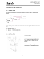
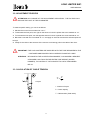
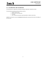
USER MANUAL
LOAD LIMITER
SW
USER MANUAL
LOAD LIMITER
SW
SINDITO, S.L.
ANY REPRODUCTION, EITHER COMPLETE OR IN PART, OF THIS MANUAL IS STRICTLY
PROHIBITED UNLESS SINDITO HAS GIVEN ITS WRITTEN CONSENT.
OTHERWISE, SINDITO RESERVES THE RIGHT TO INITIATE ALL APROPIATE ACTIONS AS
ESTABLISHED IN LAW
SINDITO RESERVES THE RIGHT TO MODIFY THIS MANUAL WITHOUT PRIOR ADVICE.
MALIMMEC3GB
REV 1
05 - 03 - 14
LOAD LIMITER SW1
USER MANUAL
INDEX
1. INTRODUCTION ........................................................................................................... 1
1.1. DIRECTIVES AND STANDARDS .................................................................. 1
2. TECHNICAL DATA ....................................................................................................... 2
3. INSTALLATION AND CONNECTIONS ......................................................................... 3
3.1.1. CONNECTION ............................................................................... 3
3.1.2. INSTALLATION .............................................................................. 3
3.2. ADJUSTMENT PROCESS............................................................................. 4
3.3. CALCULATION OF CABLE TENSION .......................................................... 4
4. MAINTENACE AND CONTROL .................................................................................... 5
4.1.1. DAILY CONTROL........................................................................... 5
4.1.2. REGULAR MAINTENANCE ........................................................... 5
4.1.3. CLEANING ..................................................................................... 5
4.1.4. STORAGE FOR LONG TIME......................................................... 5
4.1.5. CALIBRATION / RE-CALIBRATIÓN .............................................. 6
5. LIMITED MANUFACTURER GUARANTEE ................................................................. 7
i
LOAD LIMITER SW1
USER MANUAL
1. INTRODUCTION
The SW load limiter has been designed to avoid the overloads, which usually appear in lifter
equipment as tower cranes, travelling cranes, elevators…
It avoids breakage in cables, hooks, wheels, beams and rails distortion, and the rest of damages and
accidents caused by overloading.
The directive 89 / 392 / CEE considers that all of the new cranes must incorporate a load limiter and
the new risk’s prevention law for safety at work remarks the need for suppression of dangerous points,
because the user is responsible for the applied loads, that cannot exceed the maximum allowable
one.
1.1. DIRECTIVES AND STANDARDS.
CE Directives list considered as reference:
¾
2009/23/EC (Non automatic weighing instruments)
¾
2004/108/EC (Electro magnetic compatibility)
¾
2006/95/EC (Low Voltage)
¾
2006/42/EC (Machines)
¾
1999/5/EC (Radio equipment); only version with radio module
¾
2002/95/EC; 2003/118/EC; 2002/96/EC ( RoHS and WEEE )
Other Standards and other documents as reference:
¾
FEM1.001
¾
CEI EN 61000-6-2 / 2006
¾
CEI EN 61000-6-4 / 2007
¾
CEI EN 61326-1 / 2007
¾
CEI EN 55011 / 2009
¾
1999/519/EC recommendation (only version with radio module)
¾
ETSI EN 301489-3 1.4.1 version (only version with radio module)
¾
ETSI EN 300220-2 2.1.1 version (only version with radio module)
1
LOAD LIMITER SW1
USER MANUAL
2. TECHNICAL DATA
SINDITO load limiters are used to control the overloads in lifter equipment as tower cranes, travelling
cranes, elevators, etc. These load limiters are supplied with the required pre-tare, to facilitate at
Technical services its assembly.
COMPULSORY:
Always YOU MUST TO TARE it once inserted with the normal crane’s load, to +10%
The load limiter can get till 7 Tones of capacity for branch and a maximum wire diameter of 28mm and
it have an overload resistance of 150% of its maximum capacity.
Under request we can supply the equipment with double system shot and finished in stainless.
Repeatability:
+/- 1%
Operation limit temperatures:
- 10º C / + 60º C
Overload
150 % F.E. ( F.E. = Crane Rated load)
:
Finish:
bichromated
Switch:
10A 125/250 Vac -40ºC +85ºC
According to EN61058-1 (10.000 cy)
According to UL1054 (6.000 cy)
Maximum Wire Diameter:
28 mm
Maximum capacity per branch:
7 Tn
2
LOAD LIMITER SW1
USER MANUAL
3. INSTALATION AND CONNECTION
3.1.1. CONNECTION
The mechanical load limiters of this range are supplied with 3 meters of cable to connect at a safe
element.
BROW
4 x 0.5
BLUE
COMUN
NO
MICRO
NC
BLACK
Earth Æ not used
On the drawing you can see the colours of the wires on the hose supplied and the function of each
one.
The connection will be:
•
Brown wire Æ Micro com.
•
Blue wire Æ Contact Normally Open
•
Black wire Æ Contact Normally Close
3.1.2. INSTALLATION
To insert the cable:
Unscrew the 2 screws of the flange marked
as “3”. Introduce the load limiter into the fix
cable of the crane as you can see of the
drawing.
Put back the flange “3” and tighten the
screws strongly till adjust against the base.
3
LOAD LIMITER SW1
USER MANUAL
3.2. ADJUSTMENT PROCESS
ATTENTION: ANY CHANGE AT THE ADJUSTMENT SUPPLIED BY THE FACTORY WILL
SUPOSE THE LOST OF THE GUARANTEE.
To make a specific setting, you can do as follows:
1º Slacken the nut and screw marked as “10-11”
2º To decrease the limit point, turn right on the sense of a clock’s pointer the screw marked as “10”
3º To increase the limit point, turn left opposite sense of a clock’s pointer the screw marked as “10”
4º Block the screw with the nut marked as “11” and apply an nut fixer to assure the selected point will
be kept.
5º Finally fix the chain to the structure of the crane to avoid strong pulls in the cable of the micro.
IMPORTANT: THE LOAD LIMITERS ARE SUPPLIED WITH THE TARE REQUIRED BY THE
CUSTOMER AND EQUIPED FOR AN SPECIFIC RANGE OF CABLE.
ATENTION: BE AWARE IN THE ACCELERATION MOMENT, CAN HAPPEN A REQUEST
OF BIGGER LOAD THAN THE SELECTED TARE WEIGHT( WATER
HAMMER), TO CONTROL IT WE SUGGEST TO USE A TEMPORIZED
RELAY.
3.3. CALCULATION OF CABLE TENSION
T=
2 ropes
P
r
r : Number of ropes
P : Crane capacity
T : Cable tension (fixed cable)
4
LOAD LIMITER SW1
USER MANUAL
4. MAINTENANCE & CONTROL
To avoid possible problems and minimize the failures and risk for people or things, it is necessary to
make a systematic and regular maintenance of the load limiter and its components.
The maintenance steps and the period to make it, are specified by the manufacturer in this user
manual.
4.1.1. DAILY CONTROL
Every time that user starts a new cycle of work with the load limiter, must check all the parts of the
load limiter by visual examination of all the system.
4.1.2. REGULAR MAINTENANCE
The Regular maintenance of the equipment has to be done minimum every 3 months by experienced
technical people.
In case of using : female screws, male screws, or a pin to fastening the equipment, check also it is in
good conditions.
In case of damage of any part, please contact to SINDITO to replace the part with an original spare
part.
4.1.3. CLEANING
If the load limiter is frequently used in greasy, dusty, damp , etc zones or spaces, it is necessary to
clean regularly the equipment.
4.1.4. STORAGE FOR LONG TIME.
•
•
•
•
General clearing of the equipment.
Protect the load limiter with a waterproof element.
Keep it in a dry place.
Let it isolated to avoid to knock.
5
LOAD LIMITER SW1
USER MANUAL
4.1.5. CALIBRATION / RE-CALIBRATION
The load limiters are supplied duly calibrated following the applicable Standards or Rules.
The load limiters can lose precision due different reasons:
•
•
•
•
Sudden raising or pulls.
Direct knocks to the load limiter
Overloads
Use in hostile environements: High temperatures, saltiness, high dump...
SINDITO recommeds to make a re-calibration once a year to guarantee the precision and liability of
the load limiter.
6
LOAD LIMITER SW1
USER MANUAL
5. LIMITED GUARANTEE
ITOWA load limiters have a guarantee period of 12 months from the date of the order, as follows:
1.- Covering any default of manufacturing or ingrained bad habit, and the all the components,
including the hand labour necessary to replace the defective pieces in our factory.
2.- The guarantee is not covering the transport cost to our factory, the transport cost is always at the
customer charge.
3.- SINDITO keep the right of replacing the defective product for a new unit.
4.- This guarantee will not cover the damages produced by incorrect installation of the device,
transport damages, any kind of handling in the device, any rough handling, or un-appropriate use,
and decline any responsibility, for the direct or indirect damages produced in this last case.
In the same way, the guarantee is cancelled for damages produced for natural disasters, electrical
shocks produced by storms and /or ground connections without following the Legal rules or
Standards.
5.- The assessment of the damages or failures corresponds only to Technical service of SINDITO
6.- The repairs that can be done during the guarantee period will be done generally by the Technical
Service Assistance of SINDITO
7.- In any case, the holder of the guarantee have the rights recognized by the Law.
8.- To request the Limited Guarantee, customer has to prove he has right of demand it, sending to
SINDITO an original invoice copy, issued directly by SINDITO or for your usual supplier.
7