1
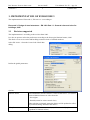
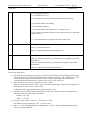
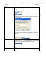
DET NORSKE VERITAS SOFTWARE Version 5.3 SESAM GeniE 1 User Manual Vol. IV – App. C4 15 March 2011 GeniE User Manual Code checking of beams Appendix C4 – Implementation of EUROCODE Table of Contents 1. IMPLEMENTATION OF EUROCODE 3 ............................................................................................................ 2 1.1 1.2 1.2.1 REVISIONS SUPPORTED ............................................................................................................................................................... 2 NOMENCLATURE – EUROCODE 3............................................................................................................................................. 9 Member check – EUROCODE 3 ....................................................................................................................... 9 DET NORSKE VERITAS SOFTWARE Version 5.3 SESAM GeniE User Manual Vol. IV – App. C4 2 15 March 2011 1. IMPLEMENTATION OF EUROCODE 3 The implementation of Eurocode 3, EN 1993-1-1 is according to: Eurocode 3: Design of steel structures – EN 1993 Part 1-1: General rules and rules for buildings, 2005 1.1 Revisions supported The implementation is according to the revision from 2005. It is also an option to select the preferences according to the Norwegian National Annex, 2006 The check covers cross-section and buckling resistance check of isolated members. Select EN-1993-1-1 from the Create Code Check Run dialog Define the global parameters: Options: National Annex Select Standard to use the “neutral” version of EN 1993-1-1, or select a preferred National Annex or select from list: - Norwegian - Danish (normal or sticter control class) When selecting a National Annex the dialogs will be updated to reflect the preferred settings defined in the annex. Safety factors Define the partial factors γM0 and γM1 (will automatically update dependant of National Annex) DET NORSKE VERITAS SOFTWARE Version 5.3 Interaction factors Compute loads when needed Purge position results, keep only worst SESAM GeniE User Manual Vol. IV – App. C4 3 15 March 2011 Interaction factors for use in equations (6.61) and (6.62) may be calculated according to method1 (Annex A) or method 2 (Annex B). Select method to be used, default selection is method 1. To reduce use of database memory, you can compute temporary loads (during codecheck execution). These loads will be deleted immediately when no longer needed. This option can affect performance on redesign, as loads must be recalculated locally every time you change member/joint settings. With this option checked, you will always use the latest FEM loads. When unchecked, you will use the FEM loads retrieved the last time you used “Generate Code Check Loads”. Note that with option checked member loads will not be available in the report nor in object properties. Only worst result along a beam will be kept. This option reduces use of database memory. Note that with option checked results for other positions than the worst one will not be available in the report nor in object properties. DET NORSKE VERITAS SOFTWARE User Manual Vol. IV – App. C4 SESAM GeniE Version 5.3 4 15 March 2011 The member code check is performed according to the chapters and sections referred to in the table below: Design consideration 5 Structural analysis Sections covered 5.5 Classification of cross section 5.5.2 Classification 1) 2) 6 Ultimate limit state 6.1 General 6.2 Resistance of cross-section 3) 6.2.2 Section properties 6.2.2.1 Gross cross-section 6.2.2.5 Effective cross-section properties of Class 4 cross-sections 6.2.3 Tension 6.2.4 Compression 6.2.5 Bending moment 6.2.6 Shear 6.2.7 Torsion 6.2.8 Bending and shear 6.2.9 Bending and axial force 6.2.9.1 Class 1 and 2 cross-sections 4) 6.2.9.2 Class 3 cross-sections 6.2.9.3 Class 4 cross-sections 6.2.10 Bending shear and axial force 6.3 Buckling resistance of members 6.3.1 Uniform members in compression DET NORSKE VERITAS SOFTWARE Version 5.3 SESAM GeniE User Manual Vol. IV – App. C4 5 15 March 2011 6.3.1.1 Buckling resistance 6.3.1.2 Buckling curves 5) 6.3.1.4 Slenderness for torsional and torsional-flexural buckling 6.3.2 Uniform members in bending 6.3.2.1 Buckling resistance 6.3.2.2 Lateral torsional buckling curves – General case 6) 6.3.2.3 Lateral torsional buckling curves for rolled sections or equivalent welded sections 6.3.3. Uniform members in bending and axial compression Annex A Method 1: Interaction factors kij for interaction formula in 6.3.3 Table A.1: Interaction factors Table A.2: Equivalent uniform moment factors 7) Annex B Method 2: Interaction factors kij for interaction formula in 6.3.3 Table B.1: Interaction factors kij for members not susceptible to torsional deformations Table B.2: Interaction factors kij for members susceptible to torsional deformations Table B.3: Equivalent uniform moment factors Notes to the table above: 1) The classification of flanges and web(s) are done for axial compression and bending about strong and weak axes for pure axial and bending moment actions respectively. The capacities for a cross section with the largest part classification in class 4 is done according to the classification corresponding to the load action in question. (See section 6.2.9.3 item (2).) 2) Pipe sections in class 4 are not supported. Class 3 is used. Flat bar sections are treated as class 3 only in automatic classification. Class 4 is not supported. If manually set to class 4, class 3 will be used. T shaped sections (degenerated I/H) are treated as class 3 only. 3) General section is treated similar to the flat bar section but is limited to class 3 behaviour. The following values are used in the calculations: height = 2*Iy / Wy width = 2*Iz / Wz 4) For pipe sections MN,Rd = Mpl,Rd( 1 – (Ned/Npl,Rd) ) is used. For channel sections equations (6.36) – (6.38) are used. 5) Ref. 6.3.1.2 (4): The paragraph in the standard says “may be”. In this implementation buckling effects are always checked. DET NORSKE VERITAS SOFTWARE Version 5.3 SESAM GeniE 6 User Manual Vol. IV – App. C4 15 March 2011 6) Ref. 6.3.2.2 (4): The paragraph in the standard says “may be”. In this implementation lateral torsional buckling effects are always checked. 7) The maximum member displacement to be used in one of the formulas is a simplified calculation based on the bending moment distribution and stiffness. Also note the following: - Un-symmetric I sections are in current implementation treated as single symmetric. - Code check of L sections is based on principal axes (u and v axes). - All cross sections are as default set to fabrication status “Unknown”. Unkown is in the code check treated as Built-up (Welded). Note that sections read from the section libraries are also set to status “Unknown”. Definition of member specific parameters: DET NORSKE VERITAS SOFTWARE Version 5.3 SESAM GeniE 7 User Manual Vol. IV – App. C4 15 March 2011 Options: Buckling length Member Length = use the geometric length of the member (capacity model). Manual = specify the length to be used Effective length factor Specify the factor to be used or select From Structure = the value assigned to the geometric beam concept is used, ref. Edit Beams The From Structure alternative is only accepted in cases with one-toone mapping between modelled beam and member. (Else factor of 1.0 will be used.) Moment factor Specify the value to be used or select rule based calculation according to the standard Buckling curve Specify the imperfection factor α to be used or select between the options: Curves a, a0, b, c. d or Automatic selection of curve according to Table 6.2 “Selection of buckling curve for cross-section Stiffener spacing Use “None” for no web stiffeners or specify the length between stiffeners. DET NORSKE VERITAS SOFTWARE Version 5.3 Lateral torsional buckling SESAM GeniE 8 User Manual Vol. IV – App. C4 15 March 2011 Specify the factors C1 and kc for lateral torsional buckling or select rule based calculation according to the standard. The alternative for calculating χLT (based on buckling curve) for lateral torsional buckling must also be selected. Note that automatic calculation of C1 only supports “simple linear moment distribution” Length between lateral supports Specify the length between lateral supports of top and bottom flange. Section classification Select how to handle the cross-section classification; - manually give the class - automatic classification - elastic = automatic classification, but limited to 3 or 4 Interaction factor method 2 Selection regarding alternatives for interaction factors, Annex B (method 2) Table B1. vs. Table B.2. Hollow and welded box specific Select hot finished (vs. cold formed) and thick welds (vs. generally) with respect to automatic definition of buckling curves, see Table 6.2. DET NORSKE VERITAS SOFTWARE SESAM GeniE Version 5.3 1.2 User Manual Vol. IV – App. C4 9 15 March 2011 Nomenclature – EUROCODE 3 1.2.1 Member check – EUROCODE 3 The print of all available results inclusive intermediate data from the member check will report the following data. Member Capacity model name (name of Beam(s) or part of beam representing the member) Loadcase Name of load case/combination under consideration Position Relative position along member longitudinal axis (start = 0, end = 1) Status Status regarding outcome of code check (OK or Failed) UfTot Value of governing usage factor Formula Reference to formula/check type causing the governing usage factor SubCheck Which check causes this result, here Eurocode EN 1993-1-1 member check GeomCheck Status regarding any violation of geometric limitations ufEuler Usage factor equal ratio for axial compression / Euler capacity ufAxial Usage factor equal ratio for axial load / design resistance for axial loading ufTorsion Usage factor due to torsion ufShearz Usage factor due to shear in local z direction ufSheary Usage factor due to shear in local y direction ufXSection Cross section usage factor according to section 6.2.9 and 6.2.10 uf646 Usage factor according to equation (6.46) uf655 Usage factor according to equation (6.55) uf661 Usage factor according to equation (6.61) uf661ax Axial contribution to usage factor according to equation (6.61) uf661mo Moment contribution to usage factor according to equation (6.61) uf661my Moment contribution (about local y axis) to usage factor according to equation (6.61) uf661mz Moment contribution (about local z axis) to usage factor according to equation (6.61) uf662 Usage factor according to equation (6.62) uf662ax Axial contribution to usage factor according to equation (6.62) uf662mo Moment contribution to usage factor according to equation (6.62) uf662my Moment contribution (about local y axis) to usage factor according to equation (6.62) uf662mz Moment contribution (about local z axis) to usage factor according to equation (6.62) sldComp slenderness ratio (beam in compression) relpos Relative position along member longitudinal axis (start = 0, end = 1) fy Yield strength E Young's modulus of elasticity gammaM0 Partial factor M0 gammaM1 Partial factor M1 NEd Design value of axial force (positive when tension) DET NORSKE VERITAS SOFTWARE Version 5.3 SESAM GeniE User Manual Vol. IV – App. C4 10 15 March 2011 MyEd Design value of moment about local y axis (strong axis) MzEd Design value of moment about local z axis (weak axis) TEd Design value of torsional moment VyEd Design value of shear force in local y direction VzEd Design value of shear force in local z direction KLy System length for buckling about local y axis KLz System length for buckling about local z axis L Length of member (length of the capacity model) Ncry Elastic flexural buckling force about local y axis Ncrz Elastic flexural buckling force about local z axis NtRd Design value of the resistance to tension force classF Cross section classification, flange classW Cross section classification, web NcRd Design resistance to nornal force for uniform compression MycRd Design resistance for bending about local y axis MzcRd Design resistance for bending about local z axis alphay The imperfection factor according to buckling curve for buckling about local y axis alphaz The imperfection factor according to buckling curve for buckling about local z axis chiy Reduction factor for buckling resistance about local y axis chiz Reduction factor for buckling resistance about local z axis NbRd Design buckling resistance of a compression member C1 Modification factor for moment distribution Mcr Elastic critical moment for lateral-torsional buckling chiLT Reduction factor for lateral-torsional buckling MbRd Design buckling resistance moment Cmy Equivalent uniform moment factor, bending about local y axis Cmz Equivalent uniform moment factor, bending about local z axis CmLT Equivalent uniform moment factor, lateral-torsional bending kyy Interaction factor kyy calculated based on method 1 or method 2 kyz Interaction factor kyz calculated based on method 1 or method 2 kzy Interaction factor kzy calculated based on method 1 or method 2 kzz Interaction factor kzz calculated based on method 1 or method 2 ----------------------------- o -----------------------------