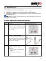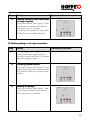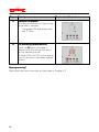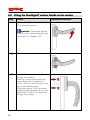
1
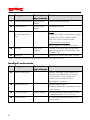
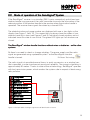
Installation/User Manual For your own attention: Please read through this Manual carefully, noting the safety information in particular. You are advised to keep it in a safe place for future reference. Manufacturer HOPPE Holding AG CH-7537 Müstair Switzerland Contacts HOPPE AG Via Friedrich Hoppe CH-7537 Müstair Switzerland +41 (0)81 851 66 00 +41 (0)81 851 66 66 [email protected] www.hoppe.com HOPPE AG Am Plausdorfer Tor 13 D-35260 Stadtallendorf Germany +49 (0)6428 932-0 +49 (0)6428 932-220 [email protected] www.hoppe.com HOPPE S.p.A. Jaufenstrasse, 16 I-39010 S. Martin i. P. (BZ) Italy +39 0473 640 111 +39 0473 641 359 [email protected] www.hoppe.com 2 Contents General ................................................................ ................................................................................................ ................................................................. .................................4 1.1 The SecuSignal® System .................................................................... 4 1.2 Guide to this Manual .......................................................................... 4 1.3 Safety regulations............................................................................... 5 1.4 Correct use as intended..................................................................... 6 1.5 Scope of delivery................................................................................ 6 2 Device and function overview ................................................................ ................................................................7 ................................7 2.1 Installation components and operating controls ................................ 7 2.2 Mode of operation of the SecuSignal® System................................... 9 2.3 State indicators on the receiver........................................................ 11 3 Preparing the radio transmitters ........................................................... ...........................................................13 ........................... 13 4 Programming ................................................................ ....................................................................................... .......................................................15 ....................... 15 4.1 Programming mode.......................................................................... 16 4.2 Programming the radio transmitters................................................. 17 4.3 Updating radio transmitters after power failure................................ 20 4.4 Delete functions................................................................................ 21 5 Installation ................................................................ ........................................................................................... ...........................................................25 ........................... 25 5.1 Removing old window handles ........................................................ 25 5.2 Fitting the SecuSignal® window handle on the window.................... 26 5.3 Installing the SecuSignal® receiver................................................... 28 6 Operation ................................................................ ............................................................................................ ............................................................30 ............................ 30 7 Troubleshooting ................................................................ ................................................................................... ...................................................31 ................... 31 8 Technical data ................................................................ ..................................................................................... .....................................................33 ..................... 33 9 Maintenance and cleaning ................................................................ ................................................................... ...................................34 ... 34 10 Disposal ................................................................ .............................................................................................. ..............................................................34 .............................. 34 11 CE conformity ................................................................ ...................................................................................... ......................................................34 ...................... 34 12 Servicing ................................................................ ............................................................................................. .............................................................34 ............................. 34 13 Guarantee ................................................................ ........................................................................................... ...........................................................35 ........................... 35 14 Index ................................................................ ................................................................................................ ................................................................37 ................................ 37 Annex ................................................................ ................................................................................................ ..................................................................... .....................................38 ..... 38 A1 Secustik® window handles ................................................................ .................................................................... ....................................38 .... 38 1 3 1 General This Manual provides you with all important information you need about installing, programming and operating your SecuSignal® System. It also provides you with information and important advice about your safety. Please note: the SecuSignal® system provides you with a quick overview of the opening states of the windows programmed. It is not however a security system or alarm system! 1.1 The SecuSignal® System SecuSignal® is a radio system consisting of at least one SecuSignal® window handle and a central receiver. The receiver stores the three states for each programmed window: • Window closed • Window tilted • Window open The following critical states are shown separately on the receiver by LEDs for each window • Window tilted • Window open. 1.2 Guide to this Manual Symbols and words used Symbol 4 Signal word Significance Danger Warning of possible serious or lethal injury to person Lightning symbol indicating explicit danger as a result of electrical power Warning Warning of possible slight injury to person or possible damage to property Caution Warning of possible defects or of total damage to the device Important information information Important advice This indicates important advice about operation 1.3 Safety regulations Caution: Caution The safety information below is intended to protect you, third parties and the device. It is essential therefore that this information is followed. Operating environment • The transmitters must not come into direct contact with moisture or water. ® The SecuSignal System is suitable for dry interiors only. • If moving the devices from a cold to warm environment, please allow the devices to adjust to the temperature before operating, otherwise, condensation damage could occur. • Do not install the SecuSignal® receiver near to devices generating strong electromagnetic fields. This could impair proper operation. Please avoid an environment subject to direct sunlight, high temperature, low temperature, moisture or wet conditions. Electrical power supply • Connect the power supply unit to an earthed mains socket outlet only with a mains voltage of 230 V AC/50 Hz. • Please use the original power supply unit only. If another power supply unit is used, this will render any guarantee claims null and void. In addition, this could involve risks and dangers as a result of electrical power, such as electric shock, fire or short-circuiting! • Please disconnect the power supply unit from the mains socket outlet if you notice signs of malfunction. If the power supply unit is damaged, do not use. Have the device inspected and, if appropriate, repaired by a qualified electrician. Children • Install the SecuSignal® receiver out of children’s reach. • Tell children how to operate the SecuSignal® System and the window handles correctly. Pay particular importance to telling them about the correct state of the window handles and in all cases (see "Operation" below). Devices Devices • For reasons relating to safety and approval (CE mark), conversions and/or modifications to the devices without authorisation are not permitted. Please do not open the devices since this would impair safety and render claims under warranty null and void. • The receiver must not be covered by textiles etc. (e.g. near coat stands) during operation since the ensuing heat build-up could result in fire. Operation • The SecuSignal® System only indicates the critical states of your windows if correctly fitted and operated. Please check your windows for malfunction or unclear operating conditions and put this right (see Chapter 7 "Troubleshooting") or call a technician. 5 • • • 1.4 Always open and close the window handles fully so as to ensure correct functioning. The window handles must always be turned to an exact vertical (tilted or closed) or horizontal position (open). Leave your house only if all windows are closed so as to minimise the risks of damage as the result of intrusion or weather. Never leave children or other persons at risk alone if windows are open so as to avoid the risk of injury falling out of the window. Correct use as intended SecuSignal® serves to indicate the states of commercially available turn-and-tilt windows. The system indicates the "critical" states "Window tilted" and "Window open" by a amber or red LED in conjunction with the number assigned to each window programmed. The product is not intended for security surveillance. Any use other than that described above constitutes use not as intended and may lead to injury or damage to property (see Chapter 1.3 "Safety regulations"). 1.5 Scope of delivery SecuSignal® receiver • Receiver with power supply unit • Installation and User Manual • Labelling stickers • Assignment diagram • Mounting hardware fixing means SecuSignal® window handle • Window handle with radio transmitter • 2 slip-on rings • Mounting hardware fixing means 6 2 Device and function over overview This provides you with an initial overview of the operating controls, displays and indicators of the SecuSignal® System and a brief description of the system's instructions for use. 2.1 Installation components and operating controls ® Figure 1: Overview of the SecuSignal System device: operating controls SecuSignal® receiver Item Designation Control / disFunction display / indicator 1 Power supply unit Power supply 2 Connector 3 Screw with dowel (Ø 6 mm) 4 Connection socket Socket Connection of the power supply unit to the receiver 5 Memory button Short-stroke button - Programming window handles - De-activating Programming mode 6 "Arrow Up" button Short-stroke button Raising group number Elbow plug Connection of the power supply unit to the receiver For wall mounting of the SecuSignal® receiver 7 Item Designation Control / disFunction display / indicator 7 "Arrow Down" button Short-stroke button Lowering group number 8 Delete button Short-stroke button Deleting program 9 Opening and programming indicators LEDs States Green LED lights: all windows closed Amber LED lights: window tilted Red LED lights: window open Programming indications See Chapter 2.3 "State indications" 10 Display Two-digit display Display of window and group numbers and programming display (see Chapter 2.3) 11 Antenna Reception of the transmitter signals ® Table 1: Installation components and operating controls of the SecuSignal receiver SecuSignal® window handle Item Designation Control / disFunction display / indicator 12 Radio transmitter Detects the state of the window on the basis of the position of the window handle’s solid spindle and sends this information to the SecuSignal® receiver 13 Window handle Open/close window Rotation generates the energy for the radio signals 14 2 slip-on rings 15 2 M5 screws Plastic sleeves Reduces excessively large drillings in window profile (12 to 10 mm) For mounting the SecuSignal® window handle Table 2: Installation components and operating controls of the SecuSignal® window handle 8 2.2 ® Mode of operation of the Se SecuSig cuSignal System ® If the SecuSignal receiver is on standby (230 V mains connection) and at least one window handle is programmed, the radio transmitter transmits the information of the relevant position of the window handle to the receiver when the window handle is operated. The receiver then signals the states by coloured LEDs. The related window and group number are displayed with one or two digits on the display (see Figure 1, Item 10). This means that you always have the states of your windows centrally in view (see Figures 2 und 3). Individual closed windows are not indicated since this state is non-critical. The green LED lights up if all windows are closed. The SecuSignal® window handle functions without wires or batteries - unlike other systems. So there’s no need to check or change a battery. The power supply and the radio signal are generated using a patented system* as the SecuSignal® window *EnOcean Technology handle is turned. The radio signal is transmitted several times, in quick succession, as a window handle is operated, in order to enhance transmission reliability. The range in a building is approximately 30 metres. Thanks to state-of-the-art technology, SecuSignal® operates with low transmission power, which renders the system safe in respect of electromagnetic pollution. Figure 2: Example table showing assignment and identification of rooms 9 Figure 3: Mode of operation of SecuSignal® 10 2.3 State indicators on the receiver This Chapter provides you with an overview of the possible state indications and their significance. The states are no longer shown at this point (states c.f. Figure 3). State indication Significance Program version The program version of the system (e.g. P1) is displayed on initial operation and each time the power is restored after a power failure. Memory blank/Reset After all programmed radio transmitters have been deleted • "00" is displayed and • all 3 LEDs flash. Programming OK The device responds as follows if programming has been successful: • "SA" (= "safe") is displayed. • The green LED lights up for 4 seconds. Memory full Up to 128 radio transmitters in up to 99 groups can be programmed. If you attempt to program more, • message "FU" (= memory "full") is displayed and • all 3 LEDs light up. 11 State indication Significance Deletion OK If deletion has been performed correctly, the device responds as follows: • Display "CL" (="clear") is shown. • The amber LED lights for 4 seconds. Programming mode active The device responds as follows when Programming mode has been activated: • "1" indicating the first memory location is displayed. • The green LED flashes. Delete function active The device responds as follows after the Delete function has been activated: • No indication is visible. • The amber LED flashes. Delete operation During the Delete operation, • the red LED lights up for 4 seconds. Display of nonnon-updated radio transmit transmitters After a power failure or after the power supply has been cut off for longer than 30 seconds and the power has then been restored, the device responds as follows: • Radio transmitters to which no connection is currently established are shown on the display every 2 seconds. • The red LED flashes. 12 3 Preparing the radio transmitters It is easier to program the radio transmitters when they have not yet been mounted on the windows. This is why you are advised to carry out installation after programming. To prepare the radio transmitters and window lever handles for programming: • Remove all SecuSignal® window handles from the packaging. • Now take a look at the enclosed assignment diagram (see also Figure 2). • Check the windows you want to equip with a SecuSignal® radio transmitter: The overall width of the radio transmitter is 36 mm. If your window profiles have trim strips or cover strips, check whether there is a level surface with a width of 18 mm from the centre of the square hole to the strip (see Figure 4). ® If so, you can easily mount the SecuSignal window handles on your windows. Figure 4 Checking the window profile • Define a numbering scheme or sequence for the windows you want to fit with ® SecuSignal window handles. The following options are available: a) Consecutive numbering for each individual window b) Some of the windows or all windows can be programmed as groups You can program several windows of one room under the same number. You can also program radio transmitters of different rooms under the same group number. Important: Note however that the states will then be shown only for the entire group and not separately for each window of this group. • • Now enter the complete numbering in the assignment diagram. Transfer the group numbers noted in the assignment diagram onto the labelling stickers supplied. If you are storing several radio transmitters under the same group number, note where they are on the assignment diagram. 13 • • Now stick the labelling stickers onto the backs of the radio transmitters so that no confusion occurs and place all window handles in order you want to program them on an adequately large work surface. Check the turning position of the square hole in each radio transmitter: detach each window handle from the radio transmitter and compare the rotary position of the square hole with the illustration in Figure 5. If necessary, correct the rotary position and carefully connect the window handle, with the handle position pointing down, back to the radio transmitter (see Figure 5). Figure 5: Checking the rotary position of the square hole • 14 Danger: Danger: If the square hole in the radio transmitter is wrongly positioned, the states will be indicated wrongly, which could be dangerous, as outlined in Chapter 1.3! 4 Programming This Chapter describes the programming and deletion functions of the SecuSignal® receiver. The radio transmitters are programmed individually on the receiver and can be deleted again either individually or all together. First put the receiver into operation to allow you to start programming: Step Activity 1 Putting receiver into operation Connect the receiver to a 230 V socket outlet. Connect the elbow plug (see Figure 1, Item 2) to the connection socket on the receiver (see Figure 1, Item 4). 2 Display The program version is shown for 2 seconds. 3 State indication "00" is shown on the display and all three LEDs flash if the memory is blank. Explanation/illustration 15 4.1 Programming mode Programming can be carried out only in Programming mode. Proceed as follows in order to activate and de-activate Programming mode: Step Activity 1 Activating Programming mode Press the button (see Figure 1, Item 5) and keep it pressed until the green LED flashes. "1", indicating the first memory location, is now shown on the display. 2 DeDe-activating Programming mode Press the button. This quits Programming mode and the device reverts to normal operating state: The green LED lights up if programming has been successful and all windows are closed. The amber or red LED lights up, depending on the state of the windows. Explanation/illustration Important: Important: The Programming mode remains active for 30 seconds if you do not press a button during this time. You must start programming during this time. If no entry is made for 30 seconds (if you do not press a button), Programming mode deactivates automatically. 16 4.2 Programming the radio transmitters Important: Important: Please note the points below to prevent malfunctions when programming. • Ensure the relevant radio transmitter and the receiver are at least 50 cm apart when programming. • Always turn the window handles fully to 90°, i.e. the handles must always be exactly vertical or exactly horizontal: • You can program a maximum of 128 radio transmitters in up to 99 groups. Figure 6: Always turn and align the window handles precisely • The SecuSignal® window handles to be programmed must be firmly in contact with the appropriate radio transmitter in closed position: Figure 7: Window handle in firm contact with the radio transmitter during programming 17 Step Activity 1 Activating Programming mode C.f. Chapter 4.1. 2 Selecting group number By pressing one of the arrow buttons (see Figure 1, Item 6 and 7), set the number of the group under which you want to program the first available radio transmitter. Tip: Pressing one of the arrow buttons for longer allows you to raise or lower the numbers quickly. 3 Programming radio transmitter Turn the window handle of the radio transmitter to be programmed from the closed to the open position and back again within 5 seconds. 4 Programming complete? complete? The device responds as follows if programming has been successful: • "SA" (="safe") is shown on the display • The green LED lights up for 4 seconds. The radio transmitter has then been registered and stored. Important: Do not program any others during this time. 18 Explanation/illustration Step Activity Explanation/illustration 5 Further programming? Note: You can program Repeat steps 2 to 4 for each further several radio transmitters under radio transmitter you want to program. the same group number. Note that Programming mode remains active only if you make a further entry within 30 seconds (c.f. Chapter 4.1). 6 DeDe-activating Programming mode Press the button or wait 30 seconds until the Programming mode de-activates automatically. 7 Check programming Test all three positions of the programmed window handles separately: • closed • open and • tilted one after the other. Check that the LEDs light up correctly (c.f. Chapter 2.2) and check the group numbers. 19 4.3 Updating radio transmitters after power failure Radio transmitters must be updated (but not reprogrammed) after a power failure or after the power supply has been cut off for longer than 30 seconds. Step Activity Explanation/illustration Display of nonnon-updated radio transmit transmitters The red LED flashes and the radio transmitters to which there is no connection are shown every 2 seconds on the display. 1 Updating Updating radio transmitters Turn all SecuSignal® window handles whose radio transmitters are to be updated from the closed to the open position and back again. 2 Checking updating Checking the update on the display is complete. Tip: ask someone to help you by turning the handles as described above and observe whether this has been shown on the display. 20 Update complete? When update is complete, the display shows the current state of your windows (see Chapter 2.2). 4.4 Delete functions The following Delete functions are possible: • Deleting the programming of an individual radio transmitter • Deleting the programming of a radio transmitters no longer required • Deleting the programming of all radio transmitters (Reset - fully deleting the content of the memory) Note: When you delete, the programming of a radio transmitter is removed from all assigned group numbers! A) Deleting programming of individual radio transmitters Step Activity 1 Activating the Deleting function Press the button (see Figure 1, Item 8) and keep it pressed until the amber LED flashes. No indication is shown on the display. 2 Deleting Deleting a radio transmitter transmitter Turn the window handle of the radio transmitter you want to delete from the closed to the open position and back again within 5 seconds. 3 Deletion complete? If the delete operation has been successful: • "CL" (= "clear") is shown on the display • The amber LED lights up Explanation/illustration 21 Step 4 Activity Deleting further radio transmitte transmitterr You need to dede-activate the Delete function so as to delete further radio transmitters. Press the button and keep it pressed until the device switches to normal operating state. Then repeat steps 1 to 4 for each further radio transmitter to be deleted. Explanation/illustration Note: It is not possible to delete programming of several radio transmitters one after the other. This is to prevent you from inadvertently deleting data by operating other window handles if the Delete function is active. B) Deleting setting of radio transmitters no longer required Step 22 Activity 1 Interrupting power supply Unplug the power supply unit from the mains socket outlet and wait 1 minute before plugging in again. 2 Activating radio transmitters Turn all window handles the settings of which are to remain stored from the closed to the open position and back again. 3 Activating the Delete function Press the button (see Figure 1, Item 8) and keep it pressed until the amber LED flashes. Nothing is shown on the display. Explanation/illustration Step 4 Activity Explanation/illustration Deleting setting of radio transmitters no longer re required Press the v button (see Figure 1, Item 7) and keep it pressed until the red LED lights up for 4 seconds. All settings not updated as described in Step 2 have now been deleted. C) Deleting settings of all radio transmitters Step Activity 1 Interrupting power supply Unplug the power supply unit from the mains socket and wait 10 seconds before plugging in again. 2 Activating Activating Delete function Press the button (see Figure 1, Item 8) and keep it pressed until the amber LED flashes. Nothing is shown on the display. 3 Deleting all settings Press the v button (see Figure 1, Item 7) and keep it pressed until the red LED lights up for 4 seconds. Explanation/illustration 23 Step Activity 4 Deletion completed? The device switches to Programming mode after 4 seconds: • The green LED and group number "1" flash. 5 DeDe-activating delete function function: Press the button and keep it pressed until the device switches to normal operating mode. All three LEDs and "00" on the display flash if the memory has been deleted entirely. Explanation/illustration Reprogramming? Reprogram the radio transmitter as described in Chapter 4.2 24 5 Installation You need to remove your old window handles before fitting your new SecuSignal® ones. 5.1 Step Removing old window handles Activity 1 Turn the old window handle to the 90° position (open). 2 Turn the cover plate also 90°. 3 Use a screwdriver to undo the fixing screws. 4 Detach your old window handle from the window profile. Explanation/illustration Important: Please ensure you dispose of the window handle in line with local waste disposal regulations (see also Chapter 10 "Disposal"). 25 5.2 Step 1 Fitting the SecuSignal® window handle on the window Activity Explanation/illustration ® Turn the SecuSignal window handle 90° to the open position. Important: The window handle must be in firm contact with the radio transmitter (c.f. Chapter 4.2)! 26 2 Turn the cover plate also 90°. 3 Turn-and-tilt windows feature 10 mm drillings as standard. However, your window profile may have drillings with a diameter of 12 mm. So check the drillings for the lugs in the window profile. If the holes have a 12 mm diameter, please use the supplied slip-on rings (see Figure 1, Item 14) to adapt the drillings accordingly. Step Activity Explanation/illustration ® 4 Now fit the SecuSignal window handle, including radio transmitter, onto the window profile. 5 Firmly screw the SecuSignal® window handle and the radio transmitter onto the window profile with the screws provided. 6 Turn the cover plate 90° back to the locked position. Turn the window handle to the tilt position and the closed position as a check. 27 5.3 Installing the SecuSignal® receiver ® We recommend you position the SecuSignal receiver in your hall. This will allow you to see at a glance quickly and easily whether all windows are closed or not. Please Please note the following points before installation: • There must be a 230 V socket in the direct vicinity. This socket should be used for the receiver only, since connection to the radio transmitters will be lost (see Chapter 4.3) if the power supply is cut off. • Install the receiver out of children’s reach. • Installation at eye level is recommended so the display can be easily read. Tip: Test the connection to the radio transmitters before installing the receiver by simply placing it on the floor of the installation location as a check. Ask someone to watch the display and then operate all window handles. If transmission from distant radio transmitters is not perfect, try out another installation location and/or note the information in Chapter 7 "Troubleshooting" (you may need to install a signal amplifier (repeater) if transmission conditions are poor). There are two installation options: A) Installing the receiver freefree-standing You can place the receiver anywhere you like. Caution: Caution Choose the installation location carefully to prevent the receiver of being knocked over or the cable being tugged. B) Wall mounting Use the enclosed fixing screw with the dowel (see Figure 1, Item 3). If you are using the dowel, drill a 6mm-diameter hole. Screw in and hang the receiver by the eyelet over the screw head (see Figure 8). Press the receiver gently down so as to fix it in position and then check if it is firm. Figure 8: Wall mounting of the SecuSignal® receiver 28 Connect the elbow plug of the power supply unit (see Figure 1, Item 4) on the receiver and plug the power supply unit into the socket. Check that the system is functioning correctly • The green LED will light up when all windows are closed. • The amber or red LED will flash and the relevant group number will be shown on the display if windows are tilted or open. ® Danger: Danger The SecuSignal receiver must not be covered by textiles (e.g. coat stands) during operation since this could cause heat build-up and lead to a fire! 29 6 Operation In normal operation, the state of each programmed window is shown, as signalled by the radio transmitter to the receiver (c.f. Chapter 2.3 "State indications on the receiver"). You will see the group numbers of the windows or window groups that are tilted or open on the display. This display goes up automatically (number 1 to 99), each number being displayed for approx. 2 seconds. Simply press one of the arrow buttons to poll the group numbers manually. This allows you to "scroll" through the list of group numbers. This is especially helpful if you have programmed a large number of radio transmitters. Checking group numbers manually Step 1 30 Activity Selecting group numb number er Press one of the arrow buttons repeatedly (see Figure 1, Item 6 and 7) to set the group number of the radio transmitter for which you want to have the state of the window checked. Explanation/illustration 7 Troubleshooting Danger: Danger Ensure that repairs to the 230 V mains are performed only by a qualified electrician. Otherwise, there will be a risk of lethal electric shock! Problem/fault Possible cause(s) Remedy Nothing shown on the display and no LED lights. Power failure or defective fuse The 230 V mains socket is defective. The power supply unit or the receiver is defective. ¾ Check the fuses in your fuse box. ¾ Have a qualified electrician repair the mains socket. ¾ Have a qualified electrician inspect the device. Radio signals are received only sporadically at the receiver or not at all. The distance between transmitter(s) and receiver is too distant or too close. Ceilings and walls may be preventing transmission (see Figure 9). Window handles and radio transmitters are not mounted correctly. ¾ Reduce or extend the distance(s) and/or try out another location for the receiver. ¾ If large distances need to be covered, install a signal amplifier (repeater; ask HOPPE AG for stockists). ¾ Check installation Figure 9: Signal attenuation as the result of ceilings and room walls Error code on display, e.g. "E1" Internal error ¾ Cut off power supply for 1 minute. Repeat this procedure twice if necessary. The display does not correspond to the current state of window. The window handle is not absolutely vertical or horizontal. ¾ Always turn the window handles fully through 90° (see Chapter 4.2). 31 Problem/fault Possible cause(s) Remedy ¾ Contact your window manufacturer to have the side/bottom hung sash fitting (=window gears) serviced. Important: Radio transmission may be adversely affected by an unfavourable electromagnetic field. Caution: Caution Do not tamper with the unit! 32 8 Technical data ® "SecuSignal "SecuSignal System" Radio transmitter Frequency Bandwidth Modulation Transfer rate Transmit power Temperature range Storage 868.3 MHz 280 kHz ASK (Amplitude Shift Keying) 120 kbps +/- 5 % max. 10 mW EIRP -20 °C to 65 °C in dry interiors Receiver Receiver Power supply unit, input UK power supply unit, input Power supply unit, output Temperature range Storage 230 V~/30 mA/50 Hz 230-240 V~/28 mA/50 Hz 9.5 V/400 mA 0 °C to 35 °C in dry interiors 33 9 Maintenance and cleaning The SecuSignal® radio transmitter is a wireless device requiring no batteries. So, it is maintenance-free. Clean the housings of the devices with a slightly damp cloth. Do not use aggressive cleaning agents or abrasives. 10 Disposal The symbol on the product and its packaging indicates that the product must not be disposed of as normal domestic waste. Users are obliged to dispose of old devices at a collection point for old electrical and electronic appliances. Waste sorting and proper disposal of your old equipment will make a contribution towards maintaining natural resources and will ensure recycling, thereby protecting human health and being considerate towards the environment. Please contact your local council, local waste disposal plant or the shop where you purchased the device for information on local collection points for used equipment. 11 CE conformity ® The SecuSignal System bears the CE mark and consequently complies with the applicable European Directives. HOPPE AG hereby confirms that this product complies with the following directives: • EC Directive 1999/5/EC "Radio and Telecommunications Terminal Equipment (R&TTE) Directive" • EC Directive 89/336/EEC "Electromagnetic Compatibility" The Declaration of Conformity is available for inspection at the manufacturer’s premises. 12 Servicing Please contact our German Hotline on should you have any questions or problems: Phone 00800 6428 932-0 Or simply refer to your HOPPE contact (see also page 2). 34 13 Guarantee HOPPE operational guarantee for door and window hardware Guarantee: As manufacturer, we guarantee, under the conditions set forth below, the durability of properly-used HOPPE hardware, over and above the seller's legal liability for material defects. The guarantee applies to the function of HOPPE door and window hardware and includes all defects which can be proved to have been caused through fault in manufacturing or material. The operational guarantee includes the following features: • transfer of the rotary motion to the door lock or the window turn-/tilt-hardware • locking mechanism (in the case of window handles with special functions: lockable, push-to-open, Secustik®) Guarantee Exclusions: All interchangeable parts, such as screws, connecting spindles etc, are excluded from this guarantee. Furthermore, no liability will be assumed for any damage caused through: • unsuitable and improper use, • incorrect or negligent treatment, • the disregard of instructions for fitting or care, alterations and repair by the enduser or a third party, • chemical or physical agents, where the surface has been improperly treated, for example by sharp instruments, • elements (door, window) and/or hardware parts (e.g. locks, hinges etc.) which do not work perfectly. Guarantee Conditions: This guarantee relates, within the guarantee period, solely to either replacing the handle free of charge or to repairing same free of charge, on behalf of the original enduser, this decision being at HOPPE's discretion. Costs and expenses, postage and packaging and similar, as incurred by the complainant, shall not be reimbursed. 35 Claim to guarantee shall only occur on presentation of the product itself and the receipt and shall not exceed the original purchase price. Guarantee period: The guarantee period shall be for 10 years and shall begin on the day of purchase by the original enduser. In the event of any claim, complainants should address themselves directly to the seller or manufacturer presenting both the product and the receipt. HOPPE Holding AG Via Friedrich Hoppe CH-7537 Müstair Switzerland +41 (0)81 851 66 00 +41 (0)81 851 66 66 [email protected] www.hoppe.com 36 14 Index Annex....................................................... 38 CE conformity .......................................... 34 Checking the square hole ........................ 14 Checking the window profile .................... 13 Cleaning................................................... 34 Correct use ................................................ 6 Delete functions ....................................... 21 All radio transmitters........................... 23 Individual radio transmitters ............... 21 Radio transmitters no longer required 22 Disposal ................................................... 34 Function overview...................................... 7 Guarantee................................................ 35 Guide ......................................................... 4 Installation................................................ 25 Installing radio transmitters ................ 26 Wall mounting..................................... 28 Mode of operation ..................................... 9 Operating controls ..................................... 7 Operation................................................. 30 Power failure............................................ 20 Preparing radio transmitters .................... 13 Product information ................................... 4 Programming ........................................... 15 Programming mode ................................. 16 Programming the radio transmitters ........ 17 Removing old window handles................ 25 Safety information ..................................... 5 Scope of delivery ....................................... 6 Signal reduction....................................... 31 State indicators........................................ 11 Technical data ......................................... 33 Troubleshooting....................................... 31 Updating radio transmitters ..................... 20 37 Annex A1 Secustik® window handles ® ® Secustik Secustik - the window lever handle with extra security that you can hear The window handles of the SecuSignal® System all feature Secustik® function. The Secustik® window handles incorporate a patented latching mechanism for integrated basic security. This function prevents the window fitting being moved by unauthorised persons on the outside. A coupling element between window handle and square pin acts as a "mechanical diode" in this case. Admittedly, it allows the window handle to be operated normally from the inside but locks the window handle if someone attempts to turn the window handle from the outside using the fitting. This means that the window handles comply with the requirements of AhS RALRG607/13. If the Secustik® window handles are turned through 180° from locked position to tilt position, the self-latching locking mechanism engages with a precision click in various handle positions. This typical Secustik® sound means greater windo window security that you can hear. hear You can find more information on the patented Secustik® system on the Internet at www.hoppe.com. German institute for quality assurance and labelling 38 Installation and User Manual IDNo.: SecuV100EN/11-2006 39