1
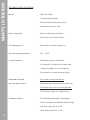
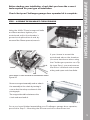
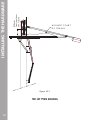
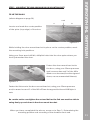
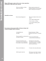
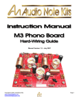
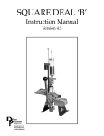
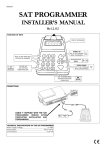
take control of your world
INSTALLER’S MANUAL
AUTOMATIC GARAGE DOOR OPENER
REVISED DATE: March 2004
IND EX
3
1. WHAT’S IN THE BOX
A list of contents you will receive with this product and
technical specifications
2. WHAT’S NOT IN THE BOX
5
A list of optional accessories available for this product.
Please contact your E.T supplier for more information.
3. RECOMMENDED TOOLS
6
A list of tools recommended for the installation of this
product
4. IMPORTANT: BEFORE INSTALLING
7
What you need to know before installing this product.
P L E A S E E N S U R E T H A T Y O U R E A D A N D U N D E R S T A N D THIS S E C T I O N B E F O R E
INSTALLING THE PRODUCT.
This section highlights any special warnings and precautions.
5. INSTALLING THE HARDWARE
6. WIRING & SCHEMATICS
17
7. PROGRAMMING & COMMISSIONING
20
8 . MAINTENANCE
23
9 . TROUBLESHOOTING
24
1 0 . WARRANTY
29
11. NOTES
30
Documented serial number and date of purchase
2
9
·
1 x Motorhead - complete
·
1 x installer’s m a n u a l
·
1 x user’s m a n u a l
In sealed bag:
·
4 x M6 x 75mm hexagonal bolts
·
4 x 6mm washers
·
1 x M8 R a w l b o l t
·
4 x M8 x 40mm coachscrews
·
1 x M8 x 90mm hexagonal bolt
·
7 x M8 Nylock nuts
·
4 x M8 x 16mm hexagonal bolts
·
2 x M8 x 25mm hexagonal bolts
·
1 x wall mount bracket
·
1 x door bracket
·
4 x No.4 3 m m x 1 6 m m c o u n t e r - s u n k s e l f - t a p p ing screws ( p o s s i e -
WHAT’S IN THE BOX
MOTORHEAD :
d r i v e head)
·
1 x emergency manual release cord kit
·
s h o r t s t r i p d o u b l e - s i d e d v e l c r o (for fixing TX to wall for wall console)
DRAWBAR:
·
1 x d r a w b a r c o m p l e t e (see technical specifications overleaf for
more details)
·
2.5 lengths perforated angle hanging straps
·
1 x link arm
·
2 x magnets and holders for chain
3
WHAT’S IN THE BOX
TECHNICAL SPECIFICATIONS
Motor
- 220v AC 50Hz
- 2 Amp single-phase
- Thermal overload protection
- Intermittent duty cycle
Drive assembly
- Worm reduction gearbox
- Sprocket and chain driven
Traveling speed:
- 8.6 metres/ minute (approx.)
Operating temperature:
- 0°C – 50°C
Control system:
- Microprocessor controlled
- On-board 2-channel receiver with
remote holiday lock-out option.
- Revolution counter load sensing.
Required front-end
spacing above door:
- Sectional overhead doors:
50mm above highest point of travel
- Trackless one-piece doors (tip-up):
275mm top edge of closed door
Drawbar options:
- 2m: Standard door with 7 foot hinge
- 2.5m: Oversize door with 8 or 9 foot hinge
- 3m: Sesco door up to H 2.3
- 3.5m: Sesco door 2.3 - 2.7m
4
1, 2 or 3 button transmitters (remote controls)
·
Escape lock (to use when no side entrance to garage)
·
Extendable link arm (to use when motor installation above
door not possible. Please ask for advice before
attempting to
fit these)
·
Safety infra-red beams or other safety input device
·
Multi-memory location receiver for individual coding security
·
Assortment of nuts, bolts, wall plugs, Rawl bolts, coachscrews,
WHAT’S NOT IN THE BOX
·
pop-rivets, dowels, self-drilling screws or chemical fasteners
needed for fixing of operator to non-wooden doors and
hanging structures.
PLEASE CONTACT YOUR E.T. PRODUCT SUPPLIER FOR MORE
INFORMATION OR TO ORDER THE ABOVE.
5
RECOMMENDED TOOLS
·
electric hammer-action drill
·
13mm masonry bit
·
5mm wood bit
·
1 0 m m s p a n n e r / wrench
·
2 x 13mm spanners/ wrenches
·
2.5mm blade flat screwdriver
·
PH01 star screwdriver
·
ha c k s a w
·
hammer
·
6ft/ 2m A-frame self-standing stepladder
·
tape measure
·
spirit level
In the case of a non-wooden door, always check with the door supplier
as to recommended fixings and types of tools needed for the installation of a garge door operator on their doors.
6
OPERATOR, PLEASE BE CERTAIN YOU HAVE READ AND
UNDERSTOOD THE FOLLOWING:
1. CHECK THAT THE GARAGE DOOR IS MECHANICALLY SOUND AS PER
MANUFACTURERS SPECIFICATIONS.
Points to inspect (general to all makes of doors):
·
Mechanisms must be secure, sound, lubricated. Door hinging and
balancing mechanisms must be fastened properly to both door and
BEFORE INSTALLING
BEFORE ATTEMPTING TO INSTALL A GARAGE DOOR
structure.
·
All nuts and bolts must be tightened according to manufacturers
specifications.
·
Do not attempt to adjust tensioning systems unless duly
qualified to do so.
·
Ensure springs are not over-stretched and are functioning properly.
·
Test door for ease of operation with no snags throughout
d o o r ’ s t r a v e l t o f u l l o p e n i n g t o f u l l c l o s i n g positions.
2 . E N S U R E T H A T A S O L I D F I X I N G P O I N T I S U S E D A B O V E D O O R for
securing the front-end bracket. A c o r r e c t l y f a b r i c a t e d b r a c k e t
extended f r o m a s o l i d s t r u c t u r e i s t o b e u s e d i n t h e c a s e o f
fascias, false panelling, header panels etc. For installations
i n b l o c k w a l l s ( c i n d e r b r i c k s ), you s h o u l d u s e a t h r o u g h - b o l t
or cross-braced plate.
3. ENSURE THAT THE HANGING BRACKETS USED TO SECURE THE
MOTORHEAD are fixed to a structure that can support the
weight and load of the garage door operator in operation.
(Rhino boarding and ceiling board DO NOT qualify as solid
structures).
7
BEFORE INSTALLING
4. INSPECT THE SPINE (TOP EDGE) OF THE DOOR for weaknesses such as
cracks or wood-knots. Ensure that the point that the door mount
bracket is attached to, will sufficiently support the weight and load
of the door when operated.
If there is any question to the above, replace or brace the spine
(top edge) of the door with stronger material.
5. ENSURE THAT ANY MECHANICAL LOCKS are either removed or securely locked in the UNLOCKED position.
6. ONE CHALLENGER DOOR OPERATOR IS NOT INTENDED TO BE USED TO
OPERATE TWO SINGLE GARAGE DOORS IN TANDEM. i.e. one motor
per installed door.
E.T. Systems will not guarentee any Challenger unit working on
more than one door. However, the Challenger units will be able to
a u t om a t e o n e c o m p l e t e d o u b l e o v e r s i z e d d o o r .
7.
PLEASE BE SURE TO MATCH THE DRAWBAR LENGTH to the type of
hinge assembly when automating oversized doors.
8. Please note that the Challenger range of garage door operators
are NOT IP55 weather-proof rated and are thus only intended for
installations in protected garage-type conditions i.e. under a roof
and out of the wind. This is even more critical when the unit is used
near a coastline.
8
Check that your Challenger garage door operator kit is complete.
STEP 1 - ASSEMBLE THE DRAWBAR TO THE MOTORHEAD
Using the 4 M6 x 75mm hexagonal bolts
and 6mm washers, tighten your
motorhead unit to the drawbar’s
geared and splined back-end, by
means of the 10mm spanner/ wrench.
Figure 9.1
BROWN
If you choose to mount the
motorhead above the drawbar
INSTALLING THE HARDWARE
Before starting your installation, check that you have the correct
tools required for your type of installation.
(for more headroom when using
the Challenger operator on a Tip
BLUE
WHITE
Up type Door), you must reverse
the motor’s forward and reverse
wiring and open and close limits.
RED
FINAL WIRING CONFIGURATION FOR REVERSE MOUNTING
Figure 9.2
Remove magnet assembly and re-attach
the assembly to the chain by turning it
over so that it ends up as shown in this
photograph.
The magnet should be between the
chain and reed switch.
Figure 9.3
Once you have finished assembling your Challenger garage door operator,
proceed to Step 2 - Mounting the link arm and door mount bracket.
9
10
from top of door
when closed
275mm
INSTALLING THE HARDWARE
HIGHEST POINT
OF TRAVEL
Figure 10.1
TIP-UP TYPE DOORS
TIP UP TYPE DOOR
(refer to diagram on page 10)
A=B
A
B
Locate and mark the center position
of the spine (top edge) of the door.
Figure 11.1 .
While holding the door mount bracket in place on the centre position, mark
the mounting hole positions.
Using your 5mm wood drill bit, drill pilot holes into the door spine where you
have just marked the door.
INSTALLING THE HARDWARE
STEP 2 - MOUNTING THE LINK ARM AND DOOR MOUNT BRACKET
Fasten the door mount bracket to
the door, using your 13mm spanners
and/ or wrenches and 2 of the M8 x
40mm coachscrews (for other types of
doors, use recommended fixtures).
Figure 11.2
Fasten the link arm to the door mount bracket, using your 13mm spanners
and/or wrenches and 1 of the M8 x 25mm hexagonal bolts and M8 Nylock
nuts.
Be certain not to over tighten the nut and bolt as the link arm must be able to
swing freely up and down in the door-mount bracket.
When you have completed the above, move on to Step 3 - Determining the
mounting position and mounting of the drawbar front-end.
11
INSTALLING THE HARDWARE
HIGHEST POINT
OF DOOR TRAVEL
DOOR BRACKET
LEVEL WITH ROLLER
IN TOP BRACKET
50mm
Figure 12.1
OVERHEAD SECTIONAL TYPE DOORS
12
(refer to diagram on page 12)
A=B
Locate and mark off the
B
centre position on the inside
fascia on the spine (top edge)
o f t h e t o p p a n e l o f t h e d o o r , in
A
line with roller in top bracket.
Figure 13.1
While holding the door mount bracket in place on the centre position
mark the mounting hole positions.
Using your 5mm wood drill bit, drill pilot holes into the door spine where
you have just marked the door.
INSTALLING THE HARDWARE
OVERHEAD SECTIONAL TYPE DOOR
Fasten the door mount bracket to the door, using your 13mm spanner
or wrench and 2 of the M8 x 40mm coach screws.
Fasten the link arm to the door
mount bracket, using your
13mm spanners and/or
wrenches and 1 of the M8 x
25mm hexagonal bolts and M8
Nylock nuts.
Figure 13.2
Be certain not to over tighten the nut and bolt as the link arm must be
able to swing freely up and down in the door-mount bracket.
When you have completed the above, move on to Step 3 - Determining
the mounting position and mounting of the drawbar front-end.
13
INSTALLING THE HARDWARE
STEP 3 - DETERMINING THE MOUNTING POSITION, AND MOUNTING OF THE
DRAWBAR FRONT-END
T I P U P T Y P E D O O R ( R e f e r t o d i a g r a m o n p a g e 10)
O V E R H E A D S E C T I O N A L T Y P E D O O R ( R e f er to diagram o n p a g e 12)
With the door in the closed position swing the link arm up fully vertical,
i n l i n e w i t h t h e c e n t r e m a r k p r e v i o u s l y d e t e r m i n e d in Step 2.
For a TIP UP TYPE DOOR:
Measure strictly 275mm (two
275mm on the wall
h u n d r e d a n d s e v e n t y - f i v e millimeters) a b o v e t h e t o p e d g e o f t h e
door along the link arm.
Mark the wall at this point.
Figure 14.1
For an OVERHEAD SECTIONAL TYPE DOOR:
Measure strictly 50mm (fift y
millimeters) above the highest
point of travel of the door
HIGHEST POINT
OF DOOR TRAVEL
along the link arm (use
horizontal tracks for door height
reference).
Mark the wall at this point.
50mm
HORIZONTAL TRACK
Figure 14.2
FOR BOTH TYPES OF INSTALLATION:
You now use y o u r 1 3 m m m a s o n a r y d r i l l b i t to d r i l l a h o l e a p p r o x i m a t e l y
90mm deep at position marked on wall.
F a s t e n t h e w a l l m o u n t b r a c k e t t o t h e w a l l u s i n g t h e M 8 R a w l b o l t by
means of y o u r 1 3m m s p a n n e r / wrench.
When you have completed the above for your type of door, move on
14
t o S t e p 4 – D e t e r m i n i n g The mo u n t i n g po s i t i o n of th e mo t o r h e a d .
TIP UP TYPE DOOR (Refer to diagram on page 10)
OVERHEAD SECTIONAL TYPE DOOR (Refer to diagram on page 12)
With the door in the closed position, fasten front-end moulding into wall
bracket using the M8 x 90mm hexagonal bolt and a M8 Nylock nut.
Fasten using your 13mm spanners and/ or wrenches.
Lift motor unit out of the way of the door travel, supporting it with a
stepladder 90O to wall.
Release the sledge from the bobbin by pulling the release lever down
90O to drawbar. This will assist in the attaching of the linkarm to the
sledge mounting.
Fasten the link arm to the sledge, using your 13mm spanners and/or
wrenches and 1 of the M8 x 25mm hexagonal bolts and M8 Nylock nuts.
Be certain not to over tighten the nut and bolt as the link arm must be
able to swing freely up and down in the sledge mounting.
INSTALLING THE HARDWARE
STEP 4 - DETERMINING MOUNTING POSITION OF MOTORHEAD UNIT
For OVERHEAD SECTIONAL TYPE DOOR installation, open door and
support motorhead so that the drawbar is 50mm above the door (level
with your spirit-level).
For TIP UP TYPE DOOR:
Open door to check travel clearance.
Ensure link arm is in the horizontal position when door is horizontal.
HIGHEST POINT
OF TRAVEL
180o
DOOR AND LINK ARM SHOULD BE LEVEL
Figure 15.1
Now proceed to Step 5 - Mounting the motorhead unit and
hanging straps.
15
INSTALLING THE HARDWARE
STEP 5 - MOUNTING MOTORHEAD UNIT AND HANGING STRAPS
Measure, cut and prepare the hanging straps according to the type of
fixed structure or rafter to which the unit is to be mounted.
PARALLEL RAFTERS
PERPENDICULAR
RAFTERS
SOLID ROOF
Figure 16.1
M o u n t t h e h a n g i n g s t r a p s to the fixed structure or rafters w i t h 2 o f t h e
M8 x 40mm coachscrews provided.
D O N O T e x c e e d o n e h a n g i n g a n g l e l e n g t h f r o m f i x e d s t r u c t u r e or
rafters. I n t h e c a s e o f d o u b l e v o l u m e r o o f c l e a r a n c e , m a n u f a c t u r e
or extend stable support structure down.
Mount powerhead to hanging straps with 2 of the M8 x 16mm
hexagonal bolts and Nylock nuts provided, using your 13mm
spanners and/ or wrenches.
Use the last 2 of the M8 x 16mm hexagonal bolts and Nylock nuts
with your 13mm spanners and/ or wrenches, to mount crossbracing.
Ensure that sufficient cross-bracing is used to disable any sideways
sway of the motorhead when in operation.
Y o u c a n n o w c o m m e n c e w i t h the programming and commissioning
16
schedule.
Figure 17.1
(+)
To (+) of receiver
WIRING & SCHEMATICS
EXT ERN A L REC EIV ER
(C)
To (-) and/ or com of receiver
200mA max.
(BT)
From N/O or neg. out of receiver
BEA MS
Figure 17.2
(+)
To (+) of beams
(C)
To (-) and/ or com of beams
200mA max.
(Bm)
From N/O of beams
17
WIRING & SCHEMATICS
WALL CONSOLE
Figure 18.1
(+) RED
(C) BLACK/ BLUE
(L) GREEN
(BT) WHITE
PROGRAMM ING
Figure 18.2
PRG JUMPER
RECEIVER (B) (L)
PROGRAMMING
PRG L.E.D.
18
PCB BUTTON
Figure 19.1
AUTO-CLOSE JUMPER
PRG JUMPER
WIRING & SCHEMATIC
A UT O- CLOSE
LOAD POT
Figure 19.2
LOAD POT
19
PROGRAMMING & COMMISSIONING
To begin programming the unit:
Power up by plugging the three-pin plug attached to the Challenger into a 15Amp
plug socket (check with electrician for latest SABS compliancy).
NOTE: The unit should beep 5 times if it has never been programmed before
and once if being reprogrammed.
Programming a remote transmitter into the onboard receiver (Fig 18.2)
The receiver can learn one code for the garage door control button and
one code for the light control button.
1.
Code the transmitter with a unique code as per make and model of
transmitter (refer to supplier for more information).
For the garage door control button :
1.
Short the pin B to the middle pin with the jumper supplied
2.
Press the desired button on the transmitter
3.
The PRG LED will flash to indicate that the code has been memorized.
4.
Remove the jumper.
For the light control button:
1.
Short the L pin to the middle pin with the jumper supplied
2.
Press the desired button on the transmitter
3.
The PRG LED will flash to indicate that the code has been memorized.
4.
Remove the jumper.
Erasing the codes on the receiver
The onboard receiver uses overwrite procedure.Recode the transmitter to a
new code and follow the process above.
Setting up the open and closed positions
The Challenger MKIII relies on magnetic limits switches for the open and
close positions and uses intelligent profiling of the door’s operation for the
overload (sensitivity) function
1.
Clear away any obstacles
2.
Move the door so that the
bobbin on the chain slides into the
carriage or sledge.
Make sure the sledge pull clip is
in the engaged position.
20
Figure 20.1
Press and release the button on the PCB or use the transmitter which
has been pre-programmed in PROGRAMMING THE TRANSMITTER INTO
THE ONBOARD RECEIVER (FIg 18.2). The door will start closing.
4.
When the door reaches the closed position, use the PCB button or the
TX to stop the door.
5.
Slide the limit magnetic
assembly situated on the chain
into position above the switch
assembly on the chassis of unit.
6.
Press and release the button
on the PCB or use the transmitFigure 21.1
ter which has been pre-programmed in PROGRAMMING THE
TRANSMITTER INTO THE ONBOARD RECEIVER. The door will start opening.
7.
When the door reaches the open position, use the PCB button or the
TX to stop the door.
8.
Slide the limit magnetic
assembly situated on the chain into
position above the switch assembly on
the chassis of unit.
9.
Test the positions of the limits:
PROGRAMMING & COMMISSIONING
3.
Press the PCB button or TX. The
operator should run to the close and
Figure 21.2
open positions and stop on the limits.
If not correct, move the limit until the
correct position has been reached.
10.
When satisfied, secure the
magnetic limit assemblies, using the
3 mm x16 mm counter sunk self
tapping screws.
Figure 21.3
Load profile and run-time can now be
programmed.
21
PROGRAMMING & COMMISSIONING
Programming the load profile
1.
Momentarily short the two pins ‘PRG’ with the jumper supplied.
The unit will close the door and find the closed limit where the unit will stop.
The unit will beep once at this point.
2.
The unit will then automatically start opening the door until the open limit is
reached.
The unit will beep once again at this point.
3.
The unit will automatically close and re-open to confirm the load profile, for
the sensitivity sensing.
Whilst doing this, the unit will emit one beep per second.
When the unit reaches the open position, the programming schedule is complete.
You may now use your garage door operator normally.
USING ADDITIONAL FEATURES
USING THE HOLIDAY LOCKOUT
FEATURE
Holiday lockout will be engaged when light input is
triggered for more than 5 sec
and deactivate if light input is
triggered again for more than 5
sec.
PROGRAMMING THE STAY OPEN TIME
FOR AUTO-CLOSE USAGE
(FIG 19.1)
1.
2.
3.
4.
ADJUSTING THE LOAD SENSING
(Fig 19.2)
To adjust the load/ obstruction
sensitivity, turn the LOAD POT
- clockwise for higher load/
obstruction sensing; and
- anticlockwise for a lower
load/ obstruction sensing.
The first operation after adjustment
of the load will produce the
number of beeps corresponding
to the load/ obstruction sensing
selected i.e. 2 beeps = 2% of 10
beeps = 10 % load.
22
5.
6.
Close the door.
Place the jumper supplied
across the two pins labeled
AUT.
Place another jumper across
the two pins labeled PRG.
Count off the required
amount of beeps for the stay
open time - each beep
equals 1 second.
When the required time is
reached, remove both the
jumpers from the PRG pins
and the AUT pins.
Replace AUT jumper once
again to select auto-close
function.
*NB. The Challenger MKIII gives three 1
second beeps warning before closing.
If 10 seconds were counted off, then
the door will start closing after 13
seconds (10 sec + 3 sec warning).
However, please bear the following points in mind:
In order to ensure maximum life of the Challenger, it is recommended that
the drawbar and chain be cleaned and lightly oiled (no grease) once every
six months. Also check that there is no dirt which could hinder the operation
of the system.
It is recommended that the door be serviced at least once a year - preferably before a wet season.
MAINTENANCE
The Challenger has been designed as a low maintenance operator therefore almost no maintenance is required.
In the case of the courtesy light bulb fusing, please note that only a globe
with the maximum rating of 40W may be used. To order your new globe, ask
for a 40W 22d bayonet cap golfball-type globe.
To replace globe, remove the light cover by unscrewing the two holding
screws on either side of the cover. Re-insert globe and replace light cover
with the open side facing the roof. This will allow heat to dissipate without
damaging the cover.
23
TROUBLESHOOTING
In all cases of testing, remove all wires from the (+), (C), (L), (Bt) and
(Bm) terminals first.
If unit operates correctly after completing this, begin re-wiring one
at a time until the problem manifests again.
Unit is dead
AC fail or fuse blown
Check 220V AC mains is
present
Check mains fuse 5Amp
Unit beeps once when triggered and will only open
on second trigger
Mains failure occured while
door was closed
This is an indication that the
processor has checked for
the close limit. All operations
after the first trigger will not
be affected and the unit will
operate normally. This will
occur every time power is reinstated.
Unit does not respond to remote transmitter
Transmitter battery flat
Check transmitter battery.
Replace if necessary.
Transmitter not
programmed into
onboard receiver
Check programming of
onboard receiver (see page
20)
Transmitter not coded to
external receiver
Check coding of external
receiver.
Wiring fault between external Check wiring of external
receiver and control card
receiver (Fig. 17.1)
24
Crosstalk between external
receiver and onboard
receiver
Check for an external
receiver close to unit. Move
external receiver 2m - 4m
away.
Incorrect frequency
transmitter
Match the frequency to the
receiver
Another transmitter
transmitting - frequency
blocked
Change remote control system
frequency
Door opens randomly on its own
Duplicate code being used
in the area
Recode the transmitter and
receiver
Faulty cable or switching
device to BT input
Remove wiring to BT input
and check cabling and
switching device on BT input
(Fig. 18.1 and 17.1)
TROUBLESHOOTING
No range from transmitter
Unit responds to open/ close trigger by chirping
and flashing light, but won’t open or close
Holiday Lock-out active
Deactivate Holiday Lockout
(see “Using Additional
Features” on page 20)
Unit beeps 3 times and then closes on its own
Auto-close active
Deactivate Auto-close
(see “Using Additional
Features” on page 20)
AUT jumper not on
Replace AUT jumper (Fig.
19.1)
Beams activated
Clear obstruction away
from door travel
Unit will not auto-close
Check beam alignment
Check beam cabling
Check beams wiring (Fig.
17.2)
25
TROUBLESHOOTING
When AUT jumper replaced for auto-close operation,
unit beeps 3 times and auto-opens
Motor and limits configuration in reverse
Swop motor reverse and
forward wiring and swop limit
switch wiring as per page 9.
Unit will not close
Beams input triggered
Remove obstacle from door
travel
Check beam alignment
Check beam cabling
Check beams wiring (see
page 17)
Door stops and reverses while closing or stops and
remains stopped while opening
Load setting too
sensitive
Reset loads (see “Using
Additional Features” on page
22)
Door operation not smooth or Clear any obstruction/
not free of snags
contact door manufaturer
26
Door has swelled and is
jamming or door weighted
because of water retention
Maintain door weatherproofing by means of oiling,
varnish or sealant - contact
door manufacturer
Door out of balance
Contact door manufacturer
Unit hung incorrectly
Re-hang as per type of door
installation (see page 10-11)
Motor and limits configuration in reverse
Swop motor reverse and
forward wiring and swop limit
switch wiring as per page 9.
Door closes then re-opens immediately
Door is closing too far and
hard up against the close
position
Reset close limit and reprogramme door (see
page 20 - 22)
Load sensitivity is too low
Re-adjust load pot (see
“Using Additional Features”
on page 22)
TROUBLESHOOTING
Door stops and reverses while openinng or stops and
remains stopped while closing.
This happens when door senses an obstruction.
Door jams in closed position
Manual locking
mechanisms engaged
Remove or disengage manual
locking mechanism
Door has swollen and is too
large for opening
Maintain door weatherproofing by means of oiling,
varnish or sealant - contact
the door manufacturer
Motor on unit hums but does not run
Starting capacitor is not
operating correctly
Check wiring on starting
capacitor (no dry joins)
Replace starting capacitor
27
TROUBLESHOOTING
Unit runs fine for a while then will not operate for a
time
Motor has overheated
due to extended use. The
thermal cutout is now
active.
NOTE: This unit is not
designed for heavy traffic,
rather for domestic
purposes only.
Re-specify the motor make
and model for high-duty
cycle (heavy traffic)
application
Use timed switching device
to keep door open via the
beam input during heavy
traffic activity time periods
Link arm flips over on top of door when unit starts to
close (tip-up type doors)
Door opens too far
Put rubber stoppers on the
door to stop against the lintel
and prevent the door from
over-opening
Unit hanging angle is
incorrect
Re-hang unit as per pages 10
to 16
Link arm twists and bends out of shape when
closing door
Link arm mounted too tight
in sledge and door mount
bracket
Loosen up fastening bolts on
either end of link arm
If you encounter any further problems, please contact the technical
support team at the supplier of your E.T. products or e-mail us
directly: [email protected]
28
·
All goods manufactured by G & C Electronics cc t/a E.T. Systems carry a 12
month factory warranty from date of invoice.
·
All goods are warranted to be free from faulty components and manufacture.
·
The following items are expressly excluded from the warranty, viz. transmitter
battery/ batteries, electric light bulb for courtesy light.
·
Faulty goods will be repaired or replaced at the sole discretion of E.T.
Systems, free of charge.
·
This warranty is subject to the goods being returned to the premises of E.T.
Systems
·
In the event of the goods being supplied by dealer, merchant, agent or
duly appointed installer of E.T. SYSTEMS, the claim must be directed to that
supplier.
·
The carriage of goods is for the customer’s account.
·
This warranty is only valid if the correct installation and application of
goods, as laid out in the applicable documentation accompanying said
goods, is adhered to.
·
All warranty claims must be accompanied by the original invoice.
·
The liability of E.T. SYSTEMS and/ or their distributors is limited as herein set
out. E.T. SYSTEMS and/ or their distributors will not be liable for consequential
or incidental damages howsoever arising.
WARRANTY
ONE-YEAR MANUFACTURER’S WARRANTY
RETURN OF GOODS
·
The return of goods for exchange or credit will only be valid for 30 days from
purchase date and shall only take place by prior arrangement with
authorised personnel at E.T. Systems.
·
E.T. Systems reserves the right to refuse the return of said goods or to levy a
10% handling fee on goods correctly supplied.
·
Credit will only be valid on the issue of an official E.T. Systems credit note.
·
All goods returned for credit or exchange will be subjected to a QA reevaluation before being accepted.
·
All returns must be accompanied by the original invoice.
·
All goods to be returned as supplied.
29
NOTES
NOTES
DATE OF PURCHASE
SERIAL NUMBER
Specifications are subject to change without notice.
www.et.co.za
30