1
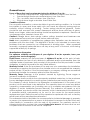
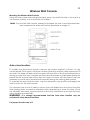
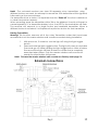
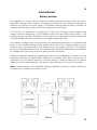
3
Introduction
digidoor III ac/dc Garage Door Operator
Congratulations on selecting the digidoor III ac/dc Operator!
This internal residential garage door automation system is designed
for low maintenance, long-term reliable service, convenience and
security.
Before you proceed, please read these instructions and
the instructions on the emergency release cord carefully!
Incorrect installation can lead to serious injury or damage!
Important Safety Instructions!
Operate the door only while in view, free of obstructions and properly
adjusted.
Keep adults, children and pets clear of the moving door.
Keep transmitter controls away from children.
Use caution when operating the manual release with the door open as it
may fall, if the spring tension is not correct.
Frequently examine the door and operator for wear, damage and
improper balance.
Ensure that a Hydro Doors accredited installer services the door regularly
Obstacle sensing is done electronically and must be properly adjusted.
This aspect must be tested at least once a year.
3
Contents of the Box
4
Fig.1
4
5
Features
24 Vdc Motor with integrated gearbox: A purpose-made 24vdc motor developed for
the door industry, which has a greater power to weight ratio and greater efficiency
than 12v motors, powers the digidoor III ac/dc.
Mains/Battery: 230Vac with 24V battery backup.
Controller: The controller is microprocessor based with a plug in printed circuit
control board.
Feature Selection: Features are link-selected.
Integrated Receiver: A high performance receiver is integrated directly on the
control board, supporting 28 users.
Obstacle Sensing: For added safety obstacle sensing is implemented in software
and by means of adjustable current sensing.
Wireless Wall Console: The console eliminates the time-consuming wiring. It has
buttons for Control, Light and Lock. Adding extra remotes via the console is easy.
Status Indicator: The digidoor III ac/dc has a prominent status indicator that shows
whether in mains or battery mode, and if the lock function is on. Also indicates Setup Mode.
Audio Alert: To assist with Set-up and provide audible warnings.
Courtesy Lamp: Both versions of the 60-watt lamp may be used.
Adjustable Open-Position Stop: The strut incorporates an adjustable stop that limits
the travel of the door in the open position. This is set during installation to provide a
reference, and serves as a safety stop when the door is used manually.
Fast Operation: This operator achieves a fast operating speed, with ramp-up and
ramp-down for smooth operation. Opening or closing of a standard sectional door
can be achieved in approximately 16 seconds.
Supports Most Types of Safety Beams: A 24volt connection is provided, which
‘times-out’ in order to conserve battery power.
Auto-Close Mode: Auto close may be selected, and occurs 30 seconds after
opening. Before auto-closing, the light flashes and an audible warning sounds for 10
seconds prior to closing.
Limits: The limits of the door travel are set automatically during the installation phase.
Specifications
Supply Voltage: 220 Vac ±10%
Maximum Current: 2Amp
Operating Speed: 130mm/sec (Typical)
Receiver Frequency: 433.92MHz
Receiver Range: Greater than 25m
5
6
General Issues
Types of Doors that can be automated using the digidoor III ac/dc:
•
Sectional overhead doors, single/double, steel or timber. Uses 3m Strut.
•
Special Height Sectional overhead doors. Uses 3.6m Strut.
•
Tip – up doors, steel or timber. Uses 2,3m Strut.
•
Roll-up doors single or double. Uses 2.36m Strut.
Condition of Doors:
For successful automation, a door should be in good working condition, i.e. it should
be possible to open and close easily with one hand, be correctly sprung and run
smoothly without sticking or binding. Torsion springs should be greased. Tracks
should be well secured with correct clearances and be clean and free of grime.
Badly worn hinges, rollers and bushings should be repaired or replaced. Remove all
unnecessary ropes, brackets, levers, etc.
Caution! Garage doors, door springs, cables, pulleys, brackets and hardware are
under extreme force and can cause serious personal injury.
Note! Most complaints of unsatisfactory garage door operation can be traced to
problems with the door itself. The digidoor III ac/dc is not intended to correct any
problems that are caused by an unbalanced or binding door. When operated
manually, a properly balanced door will stay at any point of its travel, while being
supported entirely by its springs.
Manufacturers Guarantee
For optimum reliability and lifespan of your digidoor III ac/dc operator, have your
garage door serviced regularly.
Hydro Doors warrants the first purchaser of digidoor III ac/dc, at the point of sale,
that the product be free of any defects in materials and/or workmanship from the
verifiable date of purchase. Upon receipt of the product the first purchaser is under
obligation to check the product for any visible defects.
Warranty Period: If the first purchaser is the end user who undertakes the installation
themselves or employs the services of an installer who is not accredited the warranty
period will be 12 months. If the first purchaser is a company utilizing an accredited
professional installer the warranty period will be 36 months.
Warranty Terms: Damage to the product caused by Lightning, Power surges or
incorrect installation is excluded.
The warranty shall constitute the sole remedy available under law to the purchaser
for any damages related to or resulting from a defective part and/or product.
The warranty is strictly limited to the reparation or replacement of the parts of this
product, which are found to be defective. The warranty does not cover any defect
caused by unreasonable use (including use not in complete accordance with the
digidoor III ac/dc installation/owners manual). The warrantor will repair, or at its
option replace, any device within the operator, which is determined to be defective
in materials and/or workmanship at no cost to the owner for the repair and/or
replacement part. Defective parts will be repaired or replaced with new or factory
rebuilt parts at the manufacturers discretion.
The warrantor shall not be liable for consequential or incidental damage to property
or person. No representative or person is authorized to assume for Hydro Doors any
other liability in connection with the sale of this product. For warranty service or
shipping instructions contact the nearest Hydro Door branch. All items must be sent
to Hydro Doors for service at the owner’s expense.
6
7
Assembly
Fitting the digidoor III ac/dc Power Head to the Strut
Note: For Roll-up Doors refer to page 11
1.
Ensure that the bullet fitting in the chain drive is opposite the tested sticker on
the Strut. (Approximately 600 mm from the closed end)
2. While aligning the motor shaft with the sprocket, fit the strut to the power head.
Fit the two mounting saddles and secure them with the M6 bolts provided.
See Fig. 2
3. Install the digidoor III ac/dc as shown on Page 10 for a single-piece Tip-up
door, or for a Sectional door as follows:
Automating a Sectional Overhead Door
(Timber, Steel or Fibre Glass, Single and Double)
With the door closed, extend and mark the vertical centre line of the door on the
wall above the door. Mark the cross line 50mm above the highest point of the top
edge of the door in its travel. Place the anchor bracket on the wall and align. Mark
the position of the mounting holes, and secure the anchor bracket to the wall.
Important! This bracket handles all the operating forces.
Secure the foot-end of the Drive Strut assembly to the anchor bracket while
supporting the motor.
Open the door and vertically align the Drive Strut assembly to the door centre line.
Prop the unit up to a horizontal position. Determine the length of the hanging
brackets needed to make a triangular fixing. Fit the hanging brackets to align with a
joist, batten or concrete member, as close to the power head as possible.
Note! The Hanging Brackets may be angled forwards or backwards, and secured to
either the front or rear mounting lugs.
With the door closed, pull the carriage release cord. Mount the door bracket to the
inside face of the door, in the centre and level with the top roller of the door. Fit the
curved door arm to the bracket and the straight arm to the carriage. Overlap the
arms so that the short section of the curved arm is horizontal, and securely bolt them
in two places.
With the door in the open position, move the Open Stop up against the Carriage
and secure it in place by means of the Self-Drilling screw provided.
Refer to Electrical Connections and Set-up, Page 12.
7
8
Fig. 2
8
9
Automating a Trackless One-Piece Door
(Tip–up Doors, Single and Double)
Extend and mark the vertical centre line of the door on the wall above the door.
Make a mark on the centre line between 300mm and 400mm above the door.
Place the Anchor Bracket on the wall and align the bracket. Mark the position of
the mounting holes, and secure the anchor bracket to the wall. Important! The
anchor bracket handles all the operating forces.
Secure the foot-end of the Drive Strut assembly to the anchor bracket while
supporting the motor end.
Open the door and vertically align the Drive Strut assembly to the door centre line.
While supporting the motor, ensure that the door’s highest point of travel clears the
Drive Strut assembly. Determine the length of the hanging bracket needed to make
a triangular fixing. Fit the hanging brackets to align with a joist, batten or concrete
member, as close to the power head as is conveniently possible. Note! The Hanging
Brackets may be angled forwards or backwards, and secured to either the front or
rear mounting lugs.
With the door closed, pull the carriage release cord. Mount the door bracket
securely to the top edge of the door on the centre line. Connect the curved door
arm to the carriage and the straight door arm to the door bracket. Caution! With the
door in the closed position, slide the carriage towards the door and overlap the
connecting door arms such that the arms form roughly a 45° angle to the door, and
securely bolt them in two places.
With the door in the open position, move the Open Stop up against the Carriage
and secure it in place by means of the Self-Drilling screw provided.
Refer to Electrical Connections and Set-up, Page 13.
Fig. 3
9
10
Automating Roll-up Doors
(Not roller-shutter)
Note! This requires a special Roll-up Kit, which is intended for automating single doors
as well as two side-by-side doors, separated by a column of not more than 600mm.
The kit suits most popular makes of roll-up doors.
Before You Start!
Check that the shaft of the roll-up door is level. Ensure that the sidetracks are clean
(free of grease and dirt) and undamaged (no bends or dents). Loosen the
sidetracks and move them to create ample side-clearance between the edge of
the door and the inside of the track, and re-tighten the fixing bolts. With the door
fully closed, check that the large springs on the shaft over-head are well greased.
This is important! Check the balance of the door. Ideally, when the door is moved
by hand and left at any point, it should not rise or fall. Adjust the springs if necessary.
Caution! Spring adjustment can be dangerous! If unsure how to proceed, consult
the door supplier or an accredited door installer.
Assembly of the digidoor III ac/dc Power Head to the Strut
1. Ensure that the bullet fitting in the chain drive is opposite the ‘Tested’ sticker on
the Strut.
2. With the open side of the Drive Strut assembly upwards (chain visible), align the
motor shaft with the sprocket and fit the strut so that the motor shaft passes
through the hole in the strut. Secure the strut to the power-head with M6 bolts in
the upper and lower positions. See fig. 4 on Page 12.
Important! Reverse the Motor Direction.
Remove the Light and the outer cover from the Power Head and locate the two
Spade connecters in the motor wires. Swap the motor wires from red/red,
green/grey to red/grey, green/red.
Assembly of the Roll-up Kit
The Roll-up kit consists of a wall-mount bracket, a “T”-piece, a crossbar, four doormount brackets and a pack of ‘Pop’ rivets. Fit the anchor bracket to the foot-end of
the Drive Strut assembly. Secure the wall-mount bracket to the Power-head. Fit the
flat bar of the ’T’ –piece to the carriage and secure it with the M8 Bolt and Nyloc nut
provided.
Slide the crossbar through the ‘T’ -piece and place a door-mount
bracket on each end of the crossbar, or two door-mount brackets in the case of a
single door, one near the edge of the door and the other at the end of the crossbar.
Mounting
Stand the unit next to the door and lean it against the wall. Position the doors at the
same level as the crossbar. With the anchor bracket centered, move the unit
towards the wall until the door-mounts touch the door. Mark the mounting holes in
the anchor bracket, and set the machine aside. Drill and fit the masonry plugs in the
floor. (Tip: Ensure the holes are clear before driving in the plugs, to avoid snapping
10
11
the bolts later.) Re-position the machine and secure the anchor bracket to the
floor. Position the door-mount brackets, one near the edge of the door and one at
the end of the crossbar, and rivet them to the bottom member of the door. Pull the
manual release cord (which should be shortened to about 50mm) and open the
door fully by hand. With the door open, mark, drill and secure the wall-bracket to
the wall. Tighten the setscrews of the wall-mount bracket.
Important! Springs to be greased, regularly checked and adjusted. If necessary,
contact an Accredited Hydro Doors Installer.
Fig. 4
11
12
Electrical Connections and Set-up
Note 1: If the Set-up needs to be repeated for any reason, refer to Factory Reset p15.
Note 2: If Mains supply is not available during installation, press the ‘Power Up Button’
to make use of battery power for Set-up. Refer to Fig. 6 on p16.
The digidoor III ac/dc is fitted with a power cord and a 15Amp moulded plug. Plug
this into a suitably positioned power socket, and:
1. Close the door manually then ensure that the manual lever is in the engaged
position (Latch Lever horizontal), and move the door by hand until it engages
with the operator.
2. Switch the power on. The controller will beep and the indicator will flash amber.
(The indicator flashes amber during set-up mode.)
3. The obstacle limit is set to maximum by the factory and can be left in this position
for initial setup unless a very lightweight door is used, in which case a lower force
may be used during installation.
4. Press the Enter button (For a lightweight door press Enter Twice). The door will
close slowly until the floor is reached. (Note: This process can be stopped, if
necessary, by pressing the Enter button again, and a further press will continue or
restart it.) The door will then open slowly until the open position is reached. The
controller will beep and the door will close and open at normal speed. The
controller will beep twice to indicate that the limits have been established.
5. To learn the first wall console (master), press the Enter button. The controller will
beep and the indicator will flash amber rapidly.
6. Press the Operate button on the Wall Console. The controller will beep.
7. To confirm, press the Operate button on the Wall Console again. The controller
will beep four times to show that set-up is complete, and the indicator will show
green (Ready).
8. Adjust the Obstacle Sensing by means of the trimmer shown in Fig.17, while
physically checking the force of the door on the shoulder. Also check that the
door is able to sense a block 40mm high placed on the floor in the centre of the
door. Note: This test should be repeated once a year.
9. If batteries are fitted as standard, connect these to the control board by
plugging in the two-way connector as shown in Fig. 6 on Page 18.
10. To complete the installation check that the door operates reliably and inform the
client/user of the safety features and the manual override procedure.
Visual and audible indications:
Visual Indication
LED indicator = Green
LED indicator = Green flashing
LED indicator = Red
LED indicator = Red flashing
Audible Indication
Single beep and lamp flash when attempting
to operate door
Double beep while attempting to close door
Feature
Mains power on
Main off – running on battery
Door locked
Battery voltage low
Door in locked mode
Beam obstructed or not
functional
12
13
Wireless Wall Console
Mounting the Wireless Wall Console
Using the screws and screw-plugs provided, mount the Wall Console to the wall in a
convenient position, out of the reach of children.
Note! Only the first wall console (master) will enable the user to record transmitters
and complete the erase all function described on page 16.
Auto-close function:
To enable the Auto-close function remove the jumper marked “A-Close” on the
control board. This function will close the door (from any position) after a period of 30
seconds. The lamp will flash and the buzzer will sound for a 10 second period prior to
closing to warn the user. If beams are fitted and the beam is interrupted during this
period the 30 second timer will re-start the timer. The timer will also reset if the user
operates a control input (remote/wall console) during the warning flash period.
To override the auto-close function, stop the operator in any position and apply the
lock function on the wall console.
The operator has a built in safety function that will disable the auto-close function
after sensing three successive obstacles while attempting to close the door. Once
the obstacle has been removed and the door fully closed the Auto-close function
will re-enable automatically.
WARNING: It is strongly recommended that the Auto-close function only be
activated if safety beams are fitted.
For jumper location see p15
13
14
Lock function:
The operator can be locked from the wireless wall console by pressing the lock
button. When locked the LED indicator on the operator will turn to RED. If any user
tries to open the door the light will flash once and the buzzer will beep once to
indicate that the door is locked. To unlock press the lock button o the wall console.
The lock function also overrides the auto-close function when selected.
Factory reset
If the installation setup has to be repeated for any reason, a factory reset can be
performed to return the operator to its original factory default state. This procedure
also erases the master wireless wall console learned during step 5, but not the ekey
remotes that have been recorded.
1. Remove power (including battery power if fitted.) (The Batteries may
be disconnected by unplugging the 2-way connector on the battery
charger board.)
2. Hold the “Enter” button while re-applying the power. The operator will
travel to the closed direction for a period and stop.
3. All limit settings and the master wall console are erased.
4. Remove all power again and re-start the setup procedure.
Using the digidoor III ac/dc on-Board Receiver
Digi e Key
The Digi e-key receiver is incorporated into the digidoor III ac/dc control board.
Each Digi e-key transmitter has a unique identity, which, together with the hopping
code, must be recorded by the on-board receiver before the system will function.
Recording a new transmitter via the Wall Console
1.
2.
3.
4.
5.
With power on, if need be, turn the light off using the light toggle
button.
Press and hold the light toggle button. The light will come on and after
5 seconds go off.
Release the button and the light will come on again.
Within 30 seconds, press the required button on the Digi-e key
transmitter. The light on the digidoor III ac/dc will go off.
To confirm, press the same button on the transmitter again and the
light on the digidoor III ac/dc will flash four times. The transmitter is
ready for use. Repeat the above for additional transmitters. If the
memory limit of 28 transmitters is reached the control board will beep
for 4 seconds to indicate full and return to normal operation.
14
15
Note! The on-board receiver can store 28 separate e-key transmitters, using
different buttons on each. An attempt to record the 29th transmitter will be ignored,
followed by a four second beep.
If a transmitter is lost or stolen, it is important that the “Erase all” function is carried out
to clear the receiver memory.
When recording, press the transmitter within 30s or the digidoor III ac/dc will revert to
normal operation. If a transmitter battery is low, the LED on the transmitter will flash.
The receiver will respond to a single button per handheld transmitter. When a
different button is recorded, it will replace the previous button for that transmitter.
Erasing Transmitters
Warning! This function removes all of the e-key Transmitter codes that have been
recorded but not the master wireless wall console recorded during installation.
1.
With power on, if need be, turn the light off using the light toggle
button.
2. Press and hold the light toggle button. The light will come on and after
5 seconds go off. Keep holding the light toggle button. After a further
five second the light will flash 6 times to confirm that a complete
erase has taken place. Only the master wireless wall console will
remain functional after this process.
Note! To erase the master wireless wall console see Factory reset page 14
External connections
Fig.5
15
16
Accessories
Battery backup
The digidoor III ac/dc has an optional battery backup feature which will allow
operation during power failures. The battery feature can be fitted as standard or
fitted as an option at a later stage. The battery backup feature allows at least 10
opening and closing cycles of the door during a power failure.
The amount of operations will depend on the door running load as well as the
battery reserve remaining in the batteries after an extended power failure. The
battery reserve will allow operation of the door up to 24hrs after a power failure has
occurred depending on the amount of usage during that time.
The battery charger and control board use advanced electronics to minimize the
drain on the battery during power failures and has a low voltage battery cut-out
feature which will disconnect the battery when the reserve power in the battery
reaches a pre-determined level. This extends the battery life and reduces the battery
re-charge time (<6 hours) once the mains power is returned.
Fitting of external equipment drawing power from the digidoor III ac/dc such as
external receivers will significantly reduce the standby time and the amount of
operations of the battery backup, however fitting of safety beams will not affect
these since the beam supply is only active when the door is in use or not closed.
Note: If Mains supply is not available during installation, press the ‘Power Up Button’
to make use of battery power for Set-up.
Fig.6
16
17
Emergency Key Release
The emergency key release is required where a garage has no service door. The key
release allows the door to be manually released from the outside in the case of a
power failure or low battery condition.
Safety Beams
Safety beams are comprised of two units, which may be mounted on either side of
the doorway. The opposing faces to which the units are to be mounted should be
reasonably parallel. Important! Choose a suitable mounting height, low enough to
protect toddlers and pets, but not lower than the underside of a typical motor
vehicle. The wire to the Safety beams may be placed in the groove on top of the
strut and wired through the spare grommet into the power head. To enable the
safety beams after installation and wiring is complete, remove the jumper marked
“BEAM” on the control board. Refer to Fig.5 on Page 16.
Note: If an attempt is made to close the door while the beam is obstructed, the
operator will beep twice to indicate that the beam is obstructed and the door
cannot close.
17