1
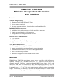
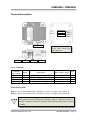
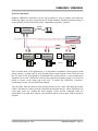
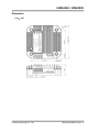
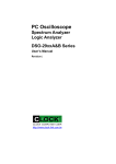
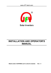
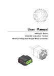
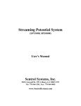
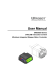
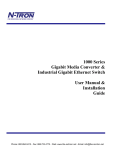
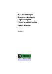
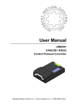
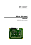
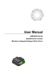
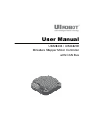
Us ser Ma anu ual UIM24 4204 / UIM24 4208 Miniatture Sttepper Motorr Contrroller with h CAN Bus UI Robot Technology Co. LTD UIM24204 / UIM24208 M24220100425EN Page | 2 UIM24204 / UIM24208 UIM24204 / UIM24208 Miniature Stepper Motor Controller with CAN Bus Features Miniature Integral Design  Miniature size 42.3mm*42.3mm*13.5mm  Fit onto motors seamlessly  Die-cast aluminum enclosure, improving heat transfer and durability Embedded DSP Microprocessor  Embedded 16-bit high-performance digital signal micro processor  Simple structured, intuitive, rich instructions  Intelligent, fault-tolerating, user-friend interface CAN2.0B Active Communication  2-wire interface  1 Mega bit/sec operation, long distance  High noise immunity due to differential bus implementation Motor Drive Characteristics      Wide supply voltage range 12 ~ 40VDC Output current 4A/8A, real-time adjustable through instruction Automatic current reduction, real-time set through instruction Full to 16th micro step resolution Dual full H-bridge with PWM constant current control Description UIM24204 and UIM24208 are miniature stepper motor controllers with CAN network capability. Through one CAN-RS232 converter (i.e. UIM25001), user device can command multiple UIM240xx controllers through RS232 port using ASCII coded instructions with minor or no knowledge about the stepper motor driving and CAN network. Instructions are simple, intuitive and fault-tolerating. UIM242xx controller can be mounted onto 42 / 57 / 86 / 110 series stepper motors seamlessly using corresponding flanges. Thickness of the controller is less than 14 millimeter. Enclosure is made of diecast aluminum providing a rugged durable protection and improves the heat dissipation. Page | 3 M24220100425EN UI Robot Technology Co. LTD UIM24204 / UIM24208 Terminal Description Phase B Phase A DIP Switch V+ GND CANH To avoid loss of terminal screws, please always keep screws tightened. CANL Screw Terminals Terminal No. / Color 1 / Red 2 / Black 3 / White 4 / Green Name V+ GND CANH CANL Description Supply voltage Supply voltage ground CAN High‐Level Voltage I/O CAN Low‐Level Voltage I/O MIN NOM MAX 12 40 0 UNI T VDC VDC Motor Wiring Pads Pad A + / A- (at the bottom of the controller): Connect to stepper motor phase A Pad B + / B- (at the bottom of the controller): Connect to stepper motor phase B ! Note: To avoid damaging the controller, make sure the phase winds are connected correctly. Resistance between leads of different phases is usually > 100KΩ. Resistance between leads of the same phase is usually < 100Ω. UI Robot Technology Co. LTD M24220100425EN Page | 4 UIM24204 / UIM24208 Typical Applications Standalone Operation UIM242xx controllers can work in a network as well as standalone. When working standalone, there is only one RS232/CAN converter linked with one UIM242xx controller. In this case, user can use wiring scheme as shown below. Stepper Motor 6~40V DC Supply DC‐ DC+ 1 12~40V DC Supply 2 UIM25001 Controller DC+ DC‐ 3 4 2 CANH CANH CANL CANL Twist Wire Pair A+ A- B+ B- 1 3 UIM242xx Stepper Controller 4 DB9 Port 120 Ohm RS232 Cable Note: For long distance transfer, the two ends of the bus should be terminated with120Ω terminating resistors. UIM25001 converter has a build-in terminating resistor. User only needs to attach a resistor at the other end of the bus. To enable the UIM25001 converter’s terminating resistor, see the UIM25001 manual. To achieve the best communication performance, CANH and CANL should use a twisted pair. Page | 5 M24220100425EN UI Robot Technology Co. LTD UIM24204 / UIM24208 Network Operation Multiple UIM242xx controllers can be wired together to form a reliable local network. Following figure provides a typical network wiring solution. Detailed terminal wiring on each controller can be found in previous “standalone Operation” solution. RS232 CANH UIM25001 Controller CANL 6‐40 VDC Power Control Room Factory UIM242xx Controller 1 Motor #1 12‐40 VDC Power UIM242xx Controller 2 Motor #2 12‐40 VDC Power CANH CANL CANH CANL CANH 12‐40 VDC Power CANL CANL 120 Ohm CANH UIM242xx Controller 100 Motor #100 Note: In multi-node CAN applications, it is important to maintain a direct point-to-point wiring scheme. A single pair of wires should connect each element of the CAN bus, and the two ends of the bus should be terminated with 120Ω resistors. A star configuration should never be used. UIM25001 converter has a build-in terminal resistor. User needs to attach a resistor at the other end of the bus. To enable the UIM25001 converter’s terminating resistor, see the UIM25001 manual. Any deviation from the point-to-point wiring scheme creates a stub. The high-speed edge of the CAN data on a stub can create reflections back down the bus. These reflections can cause data errors by eroding the noise margin of the system. Although stubs are unavoidable in a multi-node system, care should be taken to keep these stubs as small as possible. UI Robot Technology Co. LTD M24220100425EN Page | 6 UIM24204 / UIM24208 Characteristics Absolute Maximum Ratings Supply Voltage 40VDC Store Temperature ‐40℃ ~ +125℃ Working Temperature ‐20℃ ~ +85℃ Working under environment exceeding maximum value could damage the controller Electrical Characteristics(Ambient Temperature 25℃) Supply Power Voltage 10V ~ 40VDC Motor Output Current Max 2A/4A/8A per phase (Adjustable through instruction) Driving Mode PWM constant current Stepping Resolution full‐step, half‐step, quarter‐step, and sixteenth‐step Insulation Resistance >100MΩ Dielectric Strength 0.5KV in one minute Communication (Ambient Temperature 25℃) Protocol Active CAN 2.0B Wiring method 2‐wire,CANH、CANL • Supports 1 Mb/s operation • ISO‐11898 standard physical layer requirements • Suitable for 12V and 24V systems • Up to 100 nodes can be connected CAN bus drive Environment Requirements Cooling Working Environment Free Air Environment Avoid dust, oil mist and corrosive gases Temperature ‐20 ℃ ~+ 85 ℃ Humidity <80%RH,n condensation, no frosting Vibration 3G Max Storage Temperature ‐40 ℃ ~+ 125 ℃ Size and Weight Size 42.3mm x 42.3mm x 13.5mm (L*W*H) Wight 0.1 kg Page | 7 M24220100425EN UI Robot Technology Co. LTD UIM24204 / UIM24208 Overview UIM24204 and UIM24208 are miniature stepper motor controllers with CAN2.0B Active bus communication capability. They can work in a network as well as standalone. Their embedded 16-bit microprocessor supports hardware digital signal processing. The CAN2.0B based communication features high-speed (1Mega bps), long distance (max 10,000 m), and high noise immunity. It is widely used in automobile/automated manufacturing/transportation management, where high reliability is critical. The physical wiring of a CAN bus network requires only one pair of wires (twisted). By linking several controllers together through the CAN bus, user can control multiple motors in a real-time fashion. To communicate with these motor controllers, user needs a CAN-RS232 converter (i.e. UIM25001 Converting Controller). The UIM25001 commands the UIM242xx controllers through CAN bus and communicates with the user devices through RS232 ASCII coded instructions. In that manner, user can operate these controllers with minor or no knowledge about the stepper motor driving and CAN protocol. Instructions are simple, intuitive and fault-tolerating. For example, to command a speed = 1000 steps/sec, following instructions are all valid: "SPD = 1000;" or "SPD: 1000;" or "SPD 1000;" or "SPD1000;" or "SPD %?&%* 1000;" If in any case, a wrong instruction is received, the controller will return and error messages. Incorrect instructions will be discarded without execution to prevent accidents. UI Robot Co. provides free Microsoft Windows XP based VB / VC demo software and corresponding source code, to facilitate the quick start of user device side programming. UIM24204 and UIM24208 are capable of providing 1.5~4A and 3 ~ 8A adjustable output current. Output current can be adjusted through instruction in a real time fashion. Once set, the value is stored in the onboard non-volatile memory. The controller also has highspeed current compensation to facilitate the motor’s high speed performance. This series of controller takes 12 ~ 40VDC power supply. UIM24204 and UIM24208 are designed to mount onto 42 / 57 / 86 / 110 series stepper motors seamlessly through corresponding flanges. The thickness of these controllers is less than 14 millimeter. The enclosure is made of die-cast aluminum which provides a rugged durable protection and improves the heat dissipation. Packing includes 4 screws and thermal compound. UI Robot Technology Co. LTD M24220100425EN Page | 8 UIM24204 / UIM24208 Communication with UIM242xx In order to operate the UIM242xx controller, a CAN-RS232 Converting Controller (UIM25001) is required between the user device and the UIM242xx controller. User device sends ASCII coded instructions through RS232 port to the UIM25001 controller. Inside UIM25001, the RS232 based instructions are translated into CAN messages and sent to UIM242xx controllers. ACK and/or feedback messages are sent back from UIM242xx controller to UIM25001 and then translated into RS232 messages, and sent to user device. Through this fashion, users do not have to understand and deal with CAN bus operations while enjoy the advantages of CAN bus, such as high speed, long distance, interference immunity, network, and easy wiring. For detailed instructions and operations on the communication between user device and UIM25001, please refer to the UIM25001 converter’s user manual. Use the Motor Control Functions Input Supply Voltage UIM242xx series controllers are featured with a wide range of input supply voltage from 12 to 40VDC. In general, higher supply voltage improves motor performance under high speed situation, but also increases the power loss and temperature. Input voltage provided to the motor and also provided to logic circuits for control and communication. Set Output Current UIM24204 and UIM24208 are capable of providing 1.5~4A and 3~8A adjustable phase current respectively. User can adjust the output current in real-time using the CUR instruction. For details about the CUR instruction, please refer to UIM25001 converting Controller’s User Manual. Enable/Disable Automatic Current Reduction To reduce the power consumption and temperature raise, UIM242xx controller has the build-in function to reduce output current by half, 0.5 seconds after the motor stopped. User can enable/disable this function in real-time using the ACR instruction. Caution has to be taken before enable this function, since current reduction also means holding torque reduction. For details about the ACR instruction, please refer to UIM25001 converting Controller’s User Manual. Set Micro Step Resolution Page | 9 M24220100425EN UI Robot Technology Co. LTD UIM24204 / UIM24208 UIM240xx controller can provide complete micro-stepping control at full-step, half-step, quarter-step, and sixteenth-step resolutions. Only during power up, the DIP setting is read as the initial value of micro step resolution. After that, the DIP value has no effect. The micro step resolution need be changed through following instruction. ON 1/4 Step 1 2 ON Half‐Step 1 2 ON Full‐Step 1 2 ON 1 2 1/16 Step Actuator User can adjust the Micro Step Resolution in real-time using the MCS instruction. For details about the MCS instruction, please refer to UIM25001 converting Controller’s User Manual. Set Desired Motor Speed Speed is defined as how many steps per second, PPS (Pulses per Second) or Hz. User can adjust the motor speed in real-time using the SPD instruction. For details about the SPD instruction, please refer to UIM25001 converting Controller’s User Manual. Set Desired Motor Direction User can adjust the motor running direction in real-time using the DIR instruction. For details about the DIR instruction, please refer to UIM25001 converting Controller’s User Manual. Set Desired Relative Displacement User can set the desired steps or micro steps (if MCS≠1) beyond current motor position in real-time using the STP instruction. Once the motor hits the commanded relative displacement, it will stop. For details about the STP instruction, please refer to UIM25001 converting Controller’s User Manual. Enable the Motor Driver User can enable the stepper motor driver (i.e. H-bridge driving circuit) in real-time using the ENABLE instruction. For details about the ENABLE instruction, please refer to UIM25001 converting Controller’s User Manual. Disable the Motor Driver User can disable the stepper motor driver (i.e. H-bridge driving circuit) in real-time using the OFFLINE instruction. Once an OFFLINE instruction is executed, the motor has no power supply, the power consumption is cut to minimum (the logic circuit is still working). User needs to use the ENABLE instruction to turn the motor driver back to working. For details about the OFFLINE instruction, please refer to UIM25001 UI Robot Technology Co. LTD M24220100425EN Page | 10 UIM24204 / UIM24208 converting Controller’s User Manual. General ACK (acknowledgement) Message After receiving an instruction, the controller will immediately return an ACK message of all current desired settings including the most current setting. Specifically, the following information is included in the ACK message: STP, SPD, DIR, MCS, CUR, ENABLE/OFFLINE, and ACR. For details about the ACK message, please refer to UIM25001 converting Controller’s User Manual. Motor Status Feedback Message Motor’s current working status can be obtained by using the FBK instruction. Once received, the controller will send back the feedback message comprising following up-todate information: displacement/steps, speed, direction, micro step resolution, current, enabled / offline status, and ACR status. For details about the FBK instruction, please refer to UIM25001 converting Controller’s User Manual. Page | 11 M24220100425EN UI Robot Technology Co. LTD UIM24204 / UIM24208 Dimension Unit:mm UI Robot Technology Co. LTD M24220100425EN Page | 12 UIM24204 / UIM24208 Installation of UIM242xx Controller 4‐ M3x10 UIM Controller Heat Sink Compound Flange Screws Flange Winding Leads (Solder to Controller) Page | 13 M24220100425EN UI Robot Technology Co. LTD