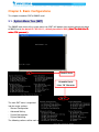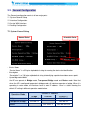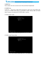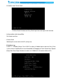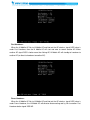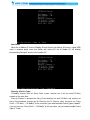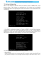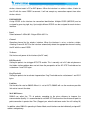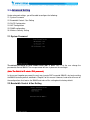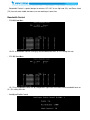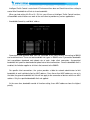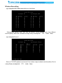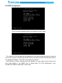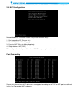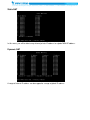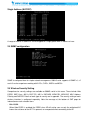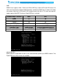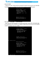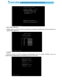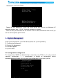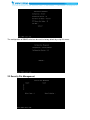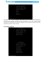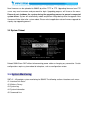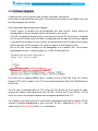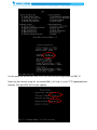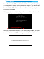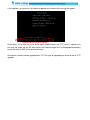
1
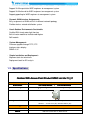
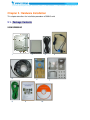
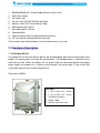
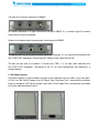
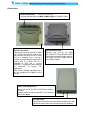
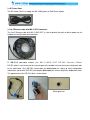
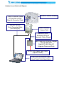
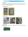
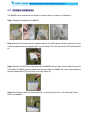
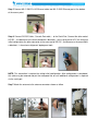
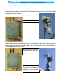
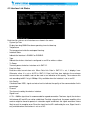
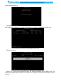
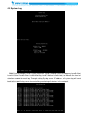
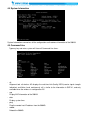
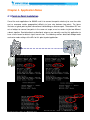
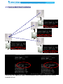
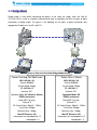
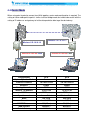
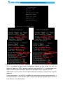
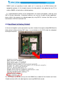
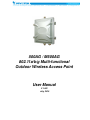
500AG / M500AG
802.11a/b/g Multi-functional
Outdoor Wireless Access Point
User Manual
V.1.002
July, 2010
Table of Contents
Table of Contents ........................................................................................... I
Chapter 1.
500AG/M500AG ........................................................................ 1
1.1.
Features .................................................................................... 1
1.2.
Specifications .......................................................................... 2
Chapter 2.
Hardware Installation ............................................................... 5
2.1.
Package Contents .................................................................... 5
2.2.
Hardware Description .............................................................. 6
2.3.
Outdoor Installation ............................................................... 12
Chapter 3.
Basic Configurations ............................................................. 15
3.1.
System Menu Tree (SMT) ...................................................... 15
3.2.
General Configuration ........................................................... 16
11. System General Setup ....................................................................................................... 16
12. Interface Configuration ................................................................................................... 21
13. Assign WAN Interface .................................................................................................... 23
14. Routing Configuration .................................................................................................... 23
3.3.
Advanced Setting .................................................................. 24
21. System Password .......................................................................................................... 24
22. Bandwidth Control & Qos Setting ................................................................................... 24
23. DHCP Configuration....................................................................................................... 28
23. DHCP Configuration....................................................................................................... 29
24. NAT Configuration .......................................................................................................... 30
25. SNMP configuration ....................................................................................................... 32
26. Wireless Security Setting ............................................................................................... 32
3.4.
System Management ............................................................. 37
31. Configuration management ............................................................................................ 37
32. Security File Management ............................................................................................. 38
33. Firmware Upgrade ......................................................................................................... 39
34. System Reboot .............................................................................................................. 40
3.5.
System Monitoring................................................................. 40
41. Interface Link Status....................................................................................................... 41
42. Wireless Survey ............................................................................................................. 42
43. System Log .................................................................................................................... 43
44. System Information ........................................................................................................ 44
45. Command Line............................................................................................................... 44
Chapter 4.
Application Notes .................................................................. 47
4.1.
Point-to-Point Installation ..................................................... 47
4.2.
Point-to-Multi Point Installation ............................................ 48
4.3.
Bridge Mode ........................................................................... 49
4.4.
Router Mode ........................................................................... 50
4.5.
Hard Reset to Factory Default .............................................. 52
4.6.
Firmware Upgrade ................................................................. 53
Chapter 1. 500AG/M500AG
This chapter describes 500AG serial in brief for your applications
1.1. Features
The 500AG serial is a multi-functional outdoor wireless Access Point including optional Router and
Bridge mode in which it can be deployed either as standalone mode or as an outdoor wireless
station. This 5GHz and 2.4GHz wireless bridge conforms to IEEE802.11 a/b/g standards and
provides a highly reliable wireless point-to-point network solution for distant locations or a
point-to-multipoint bridge. With its built-in 802.1x client for authentication, it will be the most ideal
candidate for wireless ISPs to deploy as a client device as appose to their existing AP infrastructure.
- Features in a Glance :
Scalable wireless distribution platform
Daisy chained wireless Hot Zones
Reliable multiple nodes performance in bridged or routed environments.
Bandwidth control module at subscriber level
High Speed Mobility (M Serial)
--High speed mobility roaming
--Support more than 12Mbps Throughput for backbone or AC link
--Support more than 140km/h high speed mobility application
- Comprehensive Security Features :
WPA-PSK / WPA-EAP with TKIP/ CCMP WPA Encryption Type support
WPA2-PSK / WPA2-EAP with TKIP/ CCMP WPA2 Encryption Type support
802.1x EAP-TLS / MD5 WEP Key support (Client and Server modes)
64/128/152 bits Dynamic WEP keys
Radius client
Hide ESSID
MAC address filtering
NAT
SSH secure telnet
- Special Security Features :
Maximum AC connect limits amount
Support Isolation to protect AP Hotspot by ping
Support pac to protect illegal client link AP configuration
Support VLAN mgmtvid for WISP engineers to management system
Support VLAN ethervid for WISP engineers to management system
Support pppoeflag for WISP engineers to management system
- Dynamic WAN Interface Assignments :
Easy assignments of WAN exit to fit in different network topology
Flexible wireless network distribution system
- Harsh Outdoor Environments Sustainable
Certified IP68 sturdy water-tight housing
Built-in heater module to facilitate cold regions
PoE module
- System Management :
Firmware upgrade through TFTP, FTP
Interface status display
SNMP v1/v2
- Simple Installation and Deployment :
Alignment tools for technicians
Deployment tools for RF analysis
1.2. Specifications
Outdoor WiFi Access Point Product SPEC List Ver:10_01
Product Name
500AG
/
Model Number
IOPIOP-OAPNBOAPNB-N500AG
/
Product Description
M500AG
IOPIOP-OAPNBOAPNB-M500AG
802.11a/b/g Dynamic Expansion Outdoor Wireless
Wireless (Hi(Hi-mobile) Access Point
Product Pictures
Operation Mode
System:Bridge / Transparent Bridge / Router
Wireless :Access Point (AP) / Wireless Station (AC)
Standard Support
Wireless
IEEE 802.11a, IEEE802.11b/g
Ethernet
IEEE 802.3, IEEE 802.3u, IEEE 802.3af
Interface
Consol
RS-232 Port
Wireless
Antenna Connector:1* Reversed Female N-type
Ethernet
1*10/100 Base-T RJ-45 Power over Ethernet (PoE)
Memory
SDRAM
64Mbyte
Flash
8Mbyte
Ethernet
Max. Bandwidth
Full Duplex:100Mbps (100Base), 10Mbps (10Base)
Half Duplex:50Mbps (100Base), 5Mbps (10Base)
Physical Spec.
Power
DC 48Volt / 1A ; AC Adapter 100V~240V Power over Ethernet (PoE)
Dimension
L*W*H:226*197*79 mm
Weight
1600g
Dusty & Waterproof
IP68
Antenna
Reversed N-type (Option)
Regulation and Compliance
US
FCC Part 15 Class B & C & E
Europe
EN 300 328, EN 301 489-1&17, EN 301 893, EN 60950 Compliant and CE Mark
Enviroment Spec.
Operating Temp
-30 (-40) - 65℃
Storage
--40 - 80℃
Humidity
0% ~ 95% Non-condensing
System Setting
Setting
Interface Operation Mode
Access Point (AP) / Wireless Station (AP Client)
System Operation Mode
Bridge / Transparent Bridge / Router
Wireless RF Spec.
Modulation Technique
802.11 b/g:DSSS (DBPSK, DQPSK, CCK)
OFDM (BPSK, QPSK, 16-QAM, 32-QAM, 64-QAM)
802.11 a :OFDM (BPSK, QPSK, 16-QAM, 64-QAM)
Receiver Sensitivity
Receiver sensitivity: (PER < 8% for 11b ; PER < 10% for 11g &11a)
802.11b Sensitivity:
DBPSK (1Mbps) -93dBm
DQPSK (2.2Mbps) -92dBm
CCK (5.5Mbps) -90dBm
CCK (11Mbps) -88dBm
802.11g Sensitivity:
BPSK(6Mbps) -89 dBm
BPSK(9Mbps) -88 dBm
QPSK(12Mbps) -86 dBm
QPSK(18Mbps) -85 dBm
16QAM(24Mbps) -83 dBm
16QAM(36Mbps) -80 dBm
64QAM(48Mbps) -77 dBm
64QAM(54Mbps) -72 dBm
802.11a Sensitivity:
BPSK(6Mbps) -88 dBm
BPSK(9Mbps) -87 dBm
QPSK(12Mbps) -85 dBm
QPSK(18Mbps) -84 dBm
16QAM(24Mbps) -82 dBm
16QAM(36Mbps) -80 dBm
64QAM(48Mbps) -76 dBm
64QAM(54Mbps) -71 dBm
Wireless Transmission Rate
802.11 b/g:11, 5.5, 2, 1 Mbps, Auto-fallback, up to 54Mbps
802.11 a:54, 48, 36, 24, 18, 12, 9, 6 Mbps, Auto-fallback
Transmitted Power
802.11b Mode:17dBm
802.11g Mode:17dBm @ 6Mbps, 15dBm @54Mbps
802.11a Mode:15dBm @ 6Mbps, 13dBm @54Mbps
Product Operate Setting
Feature
Main Feature:
Feature:
1.Daisy Chain
2.DC-Mesh
3.High Speed Mobility (M Series)
Special Feature:
Feature:
1.Bridge Mode LAN DHCP
4.Multiple ESSID (VLAN)
7.Wireless Multicast Rate
10.QoS
2.Dynamic WAN/LAN 3.Multiple RF Module
5.Multicast Filter
6.Wireless Limited / Fixed Rate
8.Max RF Distance
11.Wireless Survey
9.Wireless Bandwidth Control
12.SNMP
13.NTP
Command Line:
Line:
1.rateadaption
7.brstp
2.alt
8.wlmtoucast
3.nodeinfo
4.wlosthreshold
9.mcastforward
13.pureg
Security
14.cpeport
5.wlretry
10.mintxrate
15.pac
6.apbmcfilter
11.mgmtvid
12.ethervid
16.pppoeflag
Main Security:
Security:
1.MS NetBIOS Filter
2.Access ESSID
5.802.1x EAP-TLS / EAP-MD5
WPA2-EAP
3.Hide ESSID
4.WEP-64/128/152bit
6.WPA-PSK / WPA-EAP
8.MAC Address Accept / Filter
7. WPA2-PSK /
9.RADIUS Server Client
10.Maximux
AC connection Number
Special Security:
Security:
1.Isolation
2.pac
3.mgmtvid
4.ethervid
5.service
6.pppoeflag
Notes on 802.11a operation frequency:
Some countries have allocated certain 802.11a frequency bands strictly for indoor use only, for
example :
CE : 5.15 ~ 5.35GHz is for indoor only. Outdoor should use 5.47 ~ 5.725GHz.
FCC : 5.15 ~ 5.25GHz is for indoor only.
DGT : 5.15 ~ 5.25GHz is not allowed to use. 5.25 ~ 5.35GHz is for indoor only.
Japan : 5.15 ~ 5.35GHz for indoor only. Need to change the band to 4.9GHz.
Do make sure the operation frequency of 500AG serial follows your local regulation. Some areas
may have penalty when operating outdoor AP in a wrong frequency band. We take no responsibility
for any penalty or loss caused by using illegal frequency band for 500AG serial.
Chapter 2. Hardware Installation
This chapter describes the installation procedure of 500AG serial
2.1. Package Contents
500AG/M500AG
2
1
5
8
3
6
9
4
7
10
1.
500AG/M500AG 802.11a/b/g Outdoor Wireless Access Point
2.
3.
4.
PoE Power Injector
AC Power Cord
2m MIL-C-5015 IP67 RS-232 Console Cable
30m MIL-C-5015 IP67 Cat-5 Ethernet Cable
5.
6.
7.
8.
9.
Wall Mounting Kit & Screw
Mast Mounting Kit & Screw
Grounding Wire
Quick Installation Guide (or download from ftp server)
10. CD: User Manual (or download from ftp server)
Please contact your local distributor if any of the above items is missing.
2.2. Hardware Description
1. The Outdoor AP Unit
The outdoor AP unit has one antenna port on top, one data/power port and one console port at the
bottom. The antenna ports are N-type female connectors. The data/power port is used to link to the
cable from the PoE. When the outdoor AP unit and the PoE are connected together with proper
power supply, the outdoor unit is turned on and initialized. The console port is used at the initial
setup and to connect to the antenna alignment kit.
Front view of 500AG
Case Spec.
1. L × W × H: 226 × 197 × 79 mm
2. L × W × H: 245 × 197 × 79 mm
(including connectors)
3. Weight: 1600g
4. Material: aluminums alloy
Top view of RF antenna connectors of 500AG
RF antenna connector is a major interface on the top of 500AG. It is a female N-type RF antenna
connector with special waterproof.
Bottom view of power/signal connector port & console port of 500AG
The port on right side of the photo is power/signal connector port. It is an 8-pin female connector with
MIL-C-5015 IP67 waterproof. Connecting to the Power & Data Output Port of PoE.
The port on right side of the photo is Console port (TBD). It is an 8-pin male connector with
MIL-C-5015 IP67 waterproof. Connecting to the PC for initial configuration and diagnostics &
troubleshooting.
2. PoE Power Injector
PoE Power Injector is used to combine the data stream and power into one cable. It has three ports,
AC IN is for 100~240V AC power from AC Power Cord, Data Input Port is connected the customer
premises equipment (CPE) by Cat-5 cable, and Power & Data Output Port is connected to the outdoor
unit by the cable described in item 5.
Connections
Antenna Connector: 1 × Reversed Female N-type
Connect to Antenna base by Male to Male N-type CFD 400 RF Cable
Special Consol Port
Connect one end of the 2M MIL-C-5015
IP67 RS-232 console port cable to this
port; connect the other end to a Serial
Port on a computer that is running a
terminal emulation program; connect the
another end to a Serial Port on a
notebook or PDA that is running
Alignment / Deployment tools program
for
technicians
to
analysis
RF
equipments.
Note: Use this console connection only if
you are configuring the 500AG via the
console.
Special Ethernet Port
Connect one end of the 30M
MIL-C-5015 IP67 Cat-5 Ethernet Cable
into this port; connect the other end into
the Power and Data Output Port on
Inline Power Injector.
Power & Data Output Port
Attach one end of the IP67 Cat-5 Ethernet cable to
this port;
attach the other end to the 30M IP67 Cat-5 Ethernet
port on the 500AG.
Data Input Port
Connect one end of the cross-over Ethernet cable to this port;
connect the other end to the Ethernet port on the computer.
3. AC Power Cord
The AC Power Cord is to supply the 100~240V power for PoE Power Injector.
4. Cat-5 Ethernet cable with MIL-C-5015 connector
The Cat-5 Ethernet cable with MIL-C-5015 IP67 is used to provide the path to deliver power for the
outdoor unit and the data communication.
5. RS-232 console cable (2m MIL-C-5015 IP67 RS-232 Console Cable)
RS-232 cable is used to connect the console port of the outdoor unit and the antenna alignment tools
or the workstation. One (RS-232) console port has black color for setting up initial configuration
information, and another (RS-232) console port (blue color) for antenna alignment /deployment tools.
The appearance of the RS-232 cable is shown below.
Water proof hat
Outdoor Access Point Install Diagram
1.5M CFD-400 RF Cable
N-Type Male to Male
Antenna Connector Cable
2M IP67 RS-232
Serial Connector Cable
(For Setting AP)
2.4GHz or 5.8GHz Antenna
500AG Wireless
Access Point
30M IP67 Cat-5
Waterproof Ethernet
Connector Cable (Power)
PoE (Power over Ethernet) Adapter
Input AC 90~240V
Output DC 48V/1A for AP
(Integrate Power and Data)
AC 90~240V Power Code Cable
(Input AC Power)
Cate 5 (RJ-45) Ethernet Cable
(Input Digital Data/Video/Audio)
6. Mounting Kit
The mounting kit is used to provide a good support for the outdoor unit and the flat panel antenna.
Please follow the installation procedure to mount the outdoor unit and the flat panel antenna. The
contents of the mounting kit are shown below.
A. Wall Mounting Kit
B. Mast Mounting Kit
7. Grounding wire
The grounding wire is used to provide the grounding path for the outdoor unit to minimize the impact of
lightening and surge.
2.3. Outdoor Installation
The 500AG can be mounted on the wall or an antenna mast as shown in the following:
Step 1 Compose the holder of the 500AG
Step 2 Connect the female end of the power cord into the PoE Injector, and then connect the male
end of the power cord into a power outlet. The red Power LED at the front of the PoE Injector will be
on.
Step 3 Connect RJ-45 Ethernet connector from the 500AG into the Power & Data Output Port on the
PoE. When the 500AG receives power over Ethernet cable, the 500AG will start its boot sequence
and the yellow Active LED at the front of the PoE will be on.
Step 4 Run Ethernet cable from Data Input Port(at the front of the PoE)to the Ethernet Port on
the PC or notebook.
Step 5 Connect MIL-C-5015 RJ-45 Ethernet cable into MIL-C-5015 Ethernet port at the bottom
of the access point.
Step 6: Connect RS-232 Cable(Console Port cable) to the Serial Port. Connect the other end of
RS-232 (the black one or the one marked with a black dot) to the serial port on a PC for setting up
initial configuration; the other connector at the same end of RS-232(the blue one or the one without
a black dot)is for antenna alignment /deployment tools.
NOTE: This connection is required for setting initial configuration. After configuration is completed,
this cable may be removed and put the waterproof hat on until additional configuration is required
via the serial port.
Step 7 Attach the antenna to the antenna connector shown as follow.
Special Notice for Waterproof Installation
Most of the problems for outdoor models are from the connector connections that loosen over time
due to vibration or other forces, even allowing moisture to penetrate the connector and seriously
affecting the data and radio signal transmit. The following recommendation is used for all outdoor
installation to be waterproofed.
Step1: Ensure fasten all connectors securely together.
RF extend cable connection
Step2: Tightly wrap two layers of self-bonding insulating tape (tapes from well-known brands are
recommended) forward and backward over the physical connection extending 2 inches beyond the
connectors or the end of heat-shrinkable tubing on the RF coaxial cable or omni-antenna connector,
and overlapping the tape on each turn.
Wrap two layers of insulating
tape on connectors to ensure
waterproof
Wrap insulating tape around
PoE cable connector and put
the cap on console connector
Chapter 3. Basic Configurations
This chapter introduces SMT of 500AG serial
3.1. System Menu Tree (SMT)
The 500AG main menu of the system menu tree (SMT) will appear after entering correct password
of 500AG serial (the default IP: 192.168.1.1 ; default password is 0000). (Note: The Web UI is ID:
admin / PW: password.
password.)
Normal Serial
Hi-mobile Serial
It has “M” Character
The main SMT menu is organized
into four major sections:
- General Configuration
- Advanced Setting
- System Management
- System Monitoring
The following sections outline each selection item.
3.2. General Configuration
The General configuration consists of four major parts:
11. System General Setup
12. Interface Configuration
13. Assign WAN interface
14. Routing Configuration
11. System General Setup
Normal Serial
Hi-mobile Serial
- Device Name
“Device Name” is a 32 bytes alphabetical string for naming the device for identification.
- Description
“Description” is a 128 bytes alphabetical string to identifying a particular outdoor access point.
- System Operation Mode
the AP can operate in Bridge mode, Transparent Bridge mode and Router mode. Note that
when the AP is configured to operate in bridge mode, all interfaces operate as bridge. When it is
operating in route mode, all interfaces have its own IP address. Here is a table showing the
default IP setting in different operation mode below:
Operation Mode
Bridge
Transparent Bridge
Router
Bridge
192.168.1.1
192.168.1.1
Default IP Address
Ethernet
Wireless-1
192.168.1.1
192.168.1.1
192.168.1.1
192.168.100.254
- NetBIOS Filter
When enabled, each client cannot be seen on Microsoft Network Neighborhood.
- DC-MESH Setup
To click the “→” key to enter a page which will help you to setup a Daisy Chain MESH node.
There are 3 DC-MESH node statuses for configuration: Disable, Gateway Node and Normal
Node. Parameters will change while DC-MESH mode is switching.
DC-MESH mode: Disable
Same DC-Mesh Group working need same ISP ID & SUB ID.
DC-MESH mode: Gateway Node
Any DC-Mesh Network Group need at least “One Gateway Node”.
DC-MESH mode: Normal Node
DC-Mesh Route Rule base on Daisy Chain hops times and signal value calculate.
- Set System Date & Set System Time
Set the date and time
- Current Clock
Indicating the current clock of the AP (set by user).
- Hi Mobility Setup
In SMT-11 ” Hi Mobility Setup:” Press RIGHT to setting, Hi Mobile features base on Daisy Chain
system structure to be backhaul transmit bandwidth and Hopping to Center Control Area. Special
design Auto Detect Signal handover functions for Hi Mobile AC to handover different APs.
Fast Handover:
When the Hi Mobile AC link to Hi Mobile AP and find out the AP wireless signal RSSI value is
under Fast Handover, then the Hi Mobile AC will start and auto to search another AP. When
another AP signal RSSI is better more than linking AP, Hi Mobile AC will standby to handover to
another AP (or direct to handover to another AP).
Force Handover:
When the Hi Mobile AC link to Hi Mobile AP and find out the AP wireless signal RSSI value is
under Force Handover, the Hi Mobile AC will director disconnecting and try link to another Fast
Handover better signal RSSI AP.
Next Good:
When the Hi Mobile AC link to Hi Mobile AP and find out the another AP wireless signal RSSI
value is compare better more than 5dBm with linking AP, the Hi Mobile AC will director
disconnecting linking AP and try link to another AP.
Diversity & Device Type:
Hi Mobility features base on Daisy Chain system structure, but it still can work DC-Mesh
network at the same time.
Diversity function is designed for Daisy Chain backhaul run with DC-Mesh and need to set
Daisy Chain backhaul interface by Rx Diversity and Tx Diversity, when you have run “Daisy
Chain” + ”DC Mesh” + ”Hi Mobility” at the same time, you need to enable Device Type at “Mobile”.
If you just have run “Daisy Chain” + ”Hi Mobility” at the same time, you just need to enable Device
Type at “Fixed”.
12. Interface Configuration
SMT-12 is for configure the Ethernet interface and wireless interface in 500AG serial. All the
physical settings of both interfaces are configured here. Each interface can be individually
enable/disable. Note the message displayed at lower left-hand corner for more information for each
selection item.
When 500AG is configured as a bridge, the IP address of 500AG is set in the Ethernet interface.
Depends on the system, DHCP server and gateway can also be set in SMT-12. When 500AG is
configured as a router, the interface configuration looks slightly different and its DHCP is set in
SMT-23 DHCP Configuration, and the gateway is set in SMT-13 Assign WAN interface.
The following settings can be configured for the wireless interface:
- Operation Mode
Wireless interface can be set as an access point (AP) or a wireless station (also called AP client
(AC)). When the interface is an AP, it accepts connection requests from wireless clients, such as
wireless internet cards in PC or WiFi phones. When the interface is a wireless station, it looks for
the AP with the same ESSID to connect. It will not accept any connection request from other
wireless clients.
- ESSID/MESSID
Assign ESSID to the interface for connection identification. Multiple ESSID (MESSID) can be
assigned by pressing right key. Up to eight different ESSID can be assigned for each wireless
interface.
- Band
Select between 2.4GHz 802.11b/g or 5GHz 802.11a.
- Channel
Operation channel for the wireless interface. When the interface is set as a wireless station,
selecting Channel 0 AUTO let the interface automatically detect the appropriate channel used by
the AP with the same ESSID.
- Tx Power
Set the transmit power of the interface (the RF card).
- RTS Threshold
Setting the packet size to trigger RTS/CTS enable. This is normally set in AC side only because
the hidden station problem does not exit from the perspective of the AP. RTS Threshold can be
set between 1 and 2312 bytes.
- Frag Threshold
Setting the packet size to activate fragmentation. Frag Threshold can be set between 1 and 2312
bytes.
- Link Rate
Set the data link rate for 500AG. When it is set to AUTO, 500AG will use the maximum possible
link rate to transmit the data.
- MAX RF Distance
500AG can adjust the TTL of packets according to the given distance to improve the
communication quality. It is recommended to set MAX RF Distance when the distance of point to
point connection is greater than 7km. (Suggest you, when the distance under 1km still setting 10)
In addition, when 500AG is operating in Router Mode, each interface can be individually assigned IP
address and gateway.
13. Assign WAN Interface
Either the Ethernet or the wireless interface can be specified as WAN and assign gateway. This only
available when the 500AG is operating in router mode.
14. Routing Configuration
Up to 12 rules of static routes can be configured here.
3.3. Advanced Setting
Under advanced settings, you will be able to configure the following:
21. System Password
22. Bandwidth Control / Qos Setting
23. DHCP Configuration
24. NAT Configuration
25. SNMP configuration
26. Wireless Security Setting
21. System Password
The default password to enter 500AG serial SMT is 0000. SMT-21 let the user change the
password to control 500AG. The new password will take in place on the next login.
(Note: The Web UI is ID: admin / PW: password.
password.)
In the case of forgotten password, the only way to enter SMT to control 500AG is by hard resetting
the 500AG to factory default, detailed in Chapter 5 of this manual. However, hard reset will erase all
the configurations that had on the 500AG and make all the setting back to factory default.
22. Bandwidth Control & Qos Setting
Bandwidth Control is special design for wireless AP & AC to run Up Load (UL) and Down Load
(DL) transmit more stable and more user can working at same time.
Bandwidth Control
- UL+DL Limit Rate
UL+DL as bandwidth control running by total bandwidth base on UL+DL setting link rate.
- UL / DL Limit Rate
UL / DL as bandwidth control run by Independent Upstream and Downstream bandwidth base on
UL / DL setting link rate.
- Intelligent Traffic Control
Intelligent Traffic Control is auto check AC link amount then base on Check Interval time setting to
control Max Bandwidth for all links to share bandwidth.
When you had setting UL+DL or UL / DL first, you still can set Intelligent Traffic Control functions;
all bandwidth control feature can work at the same time to provide very various applications.
- Bandwidth Control by each MAC address
Downstream and upstream data rates for subscriber or the client devices connecting to 500AG
can be defined here. There are two bandwidth limit types in 500AG serial. Symmetrical bandwidth
limit consolidates download and upload rate of each single client connection. Asymmetrical
bandwidth limit specifies download and upload rate of client connections. Once the bandwidth limit is
enabled, the limitation applies to all clients that connect to the 500AG.
For specific client connections, the system provides a table for network administrator to limit
bandwidth of each individual client by MAC address. Once these client MAC addresses are set in
the table, the general bandwidth limit rule will not apply to the connection of devices with these MAC
address. Only the specified bandwidth limit rule applied.
At the same time, bandwidth control all function setting, those MAC addresses bear the highest
priority.
Wireless Qos setting
- Qos Setting By DSCP (Differentiated Services Code Point)
Differentiated Services Code Point base on different service package styles have different
transmit priority. QoS-DSCP standard to setting Priority including Mail 、FTP 、Audio、Video 。
- Qos Setting By Protocol
Base on TCP/UDP protocol and transmit Port number range to decide transmit priority. Port to
setting Priority including Mail 、FTP 、Audio、Video
23. DHCP Configuration
DHCP can work at bridge intranet LAN enviroment or router mode.
The scope of DHCP client pool that corresponds to the selected interface and subnet are defined
in this menu. Lease (D) is the duration that the DHCP server grants to the DHCP client permission to
use a particular IP address. Lease (M) is the maximum lease time.
Each Ethernet or wireless interface can be the gateway of its own subnet. Hence there can be
three subnet domains in one 500AG serial in routing mode. This DHCP configuration is only
available when 500AG is operating in router mode.
23. DHCP Configuration
DHCP can work at bridge intranet LAN enviroment or router mode.
The scope of DHCP client pool that corresponds to the selected interface and subnet are defined in
this menu. Lease (D) is the duration that the DHCP server grants to the DHCP client permission to
use a particular IP address. Lease (M) is the maximum lease time.
Each Ethernet or wireless interface can be the gateway of its own subnet. Hence there can be
three subnet domains in one 500AG serial in routing mode. This DHCP configuration is only
available when 500AG is operating in router mode.
24. NAT Configuration
Network Address Translation can be setup in four different ways :
1. Port forwarding NAT (Server sets)
2. Static NAT (One to One Mapping)
3. Dynamic NAT (Many to Many Mapping)
4. Single Address NAT (PAT)
This configuration in only available when 500AG is operating in router mode.
Port Forwarding
Server sets where internal IP addresses are mapped according to the TCP or UDP port are defined
in this Port Forwarding NAT sub-menu.
Static NAT
In this menu, you will be able to map internal private IP address to a global WAN IP address.
Dynamic NAT
A range of internal IP address can be mapped to a range of global IP address.
Single Address (NAT/PAT)
A range of internal IP addresses can be mapped to a single global WAN IP addresses here.
25. SNMP configuration
SNMP is configured here for simple network management. 500AG serial supports all SNMP v1, v2
and v3. we has experience working with ILECs, CLECs, WISPs and MSOs.
26. Wireless Security Setting
Comprehensive security settings are available on 500AG serial in this menu. These include Hide
ESSID, WEP Keys, 802.1x EAP-TLS, 802.1x EAP-MD5, WPA-PSK, WPA-EAP, MAC Address
Filtering and RADIUS. Details of each type of security are in appendix. The security setting of each
wireless interface is configured separately. Note the message at the bottom of SMT page for
information on each selection items.
- Hide ESSID
When Hide ESSID is enabled, the ESSID of an AP will not be seen so only the authorized AC
knows the existence of the AP. This prevents an unexpected client connecting to the AP.
- WEP
500AG serial supports 64-bit, 128-bit and 152-bit WEP key in both ASCII and HEX format. Do
make sure the correctly number of digits/characters and format of WEP key as shown in the table
are entered. Note that in HEX format, HEX number cannot start with “0”. An error message will
appear upon exiting SMT-26 when an illegal WEP key is entered.
Number of digit / character
ASCII
HEX
64-bit
5
10
128-bit
13
26
152-bit
16
32
Can use Number or Character
0~9 & a~z
0~9 & a~f
Example1-64bit
power
abcdef1230
Example2-128bit
1power5429395
0123456789abcdef9876543210
Example3-152bit
Iopower035429395
fedcba0123456789abcdef9876543210
- 802.1x EAP-TLS
Both 64-bit and 128-bit WEP can be set for reauthentication period up to 65535 seconds. Two
Eapol (EAP over LAN) versions are available.
- 802.1x EAP-MD5
WEP Key of 64-bit, 128-bit and 152-bit in both ASCII and HEX format can be set for EAP-MD5.
Two Eapol version are available with reauthentication period of up to 65535 seconds.
- WPA-PSK / WPA2-PSK / WPA/WPA2-PSK
Both TKIP and CCMP encryption are available for WPA-PSK / WPA2-PSK / WPA/WPA2-PSK.
Pre-shared key of 8 to 63 characters are required. Group Rekey Interval can be set up to 65536
seconds. Two Eapol version are available.
- WPA-EAP / WPA2-EAP / WPA/WPA2-EAP
Both TKIP and CCMP encryption are available for WPA-EAP / WPA2-EAP / WPA/WPA2-EAP.
Pre-shared key of 8 to 63 characters are required. Group Rekey Interval can be set up to 65536
seconds. Two Eapol version are available.
- MAC Address Filtering
500AG serial can control the client connection by accepting or blocking the traffic from devices of
specific MAC addresses.
- RADIUS
RADIUS settings for 802.1x protocol authenticating with the remote RADIUS server for
authenticating, authorization and accounting are set in this menu.
- Maximum AC Connection Number
Depend on your deployments system and service design plan, you can set Maximum AC
connection amounts from 1~255 AC. (Default 0 is disable this function)
When too many AC demand to link AP, need the useful AC release connection after new AC just
can has connect right to get AP service.
3.4. System Management
Under System Management, you will be able to operate the system by following:
31. Configuration Management
32. Security File Management
33. Firmware Upgrade
34. System reboot
31. Configuration management
The configuration of 500AG can be backed-up or restored by using TFTP here. In a daisy chained
sequential configurations, it is recommended to backup all configurations before
uploading/upgrading firmware. You may name your configuration file in any ways you like.
The configuration of 500AG serial can be reset to factory default by using this menu.
32. Security File Management
For running EAP_TLS secure connection, network administrators may need to able to upload User
Certificate, Root Certificate and RSA Key file to the system. In this menu, system allowed
administrators to upload these Certificate files through TFTP server to the access point. Please refer
Annotations for more on wireless security.
33. Firmware Upgrade
New firmware can be uploaded to 500AG by either TFTP or FTP. Upgrading firmware from FTP
server may need username and password for login. Upgrading progress will show on the menu.
Please do not shutdown the system during the upgrading process to prevent unexpected
system failure. System will automatically reboot and perform image backup after the upgrade. New
firmware will take effect after system reboot. Please refer to application note on firmware upgrade for
step by step upgrading process.
34. System Reboot
Reboot 500AG from SMT without disconnecting power cable or changing any connection. Certain
configurations require system reboot to take place, such as configuration restore.
3.5. System Monitoring
SMT-41 ~ 45 provides system monitoring for 500AG. The following sections introduce each menu :
41. Interface Link Status
42. Wireless Survey
43. System log
44. System Information
45. Command Line
41. Interface Link Status
Real-time link statuses of all interfaces are shown in the menu.
- System Up Time
Display how long 500AG has been operating since last boot-up.
- Temperature
The temperature inside the waterproof housing.
- Interface Status
Indicate the interface is ENABLE or DISABLE.
- Type
Indicate the wireless interface is configured as an AP or wireless station.
- Tx-Power
Transmit power of wireless interface set in SMT-12.
- Data Link Rate
Real-time data transmission rate. When Data Link Rate in SMT-12 is set, it displays here.
Otherwise, when it is set as AUTO in SMT-12, Data Link Rate here indicates the maximum
transmission rate available, and can be used as an indication of link quality. The maximum link
rate according to 802.11a/g is 54Mbps. Only available when the interface is set as an AC.
- Link Quality
Calculated from RSSI, signal and noise level to indicate the quality of the communication link in
percentage.
- Channel
The channel used by the wireless interface.
- Signal Level
A -70 ~ -50dBm signal level is recommended for a good connection. Too low a signal, the wireless
link between AP and AC can not be established. Too high a signal level, the power amplifier at the
receiver might be forced to operate in saturation region and distorts the signal waveform. Hence
likely to result in reception error. Since the signal level at AP is defined by the user, Signal Level is
only available when the interface is set as an AC.
42. Wireless Survey
- Associated client list
MAC addresses of all clients associate with AP wireless interface on 500AG are shown here.
You can enable Auto Refresh and change Refresh time.
- Wireless site survey
Base on AC status to scan space AP signal, but when the interface set AP mode, it also can
momentary change from AP status to AC status; the system will auto show information to warm
operator.
43. System Log
500AG serial provides seven system log levels (Level1=Debug Level2=Emergency Level3=Alert
Level4=Critical Level5=Error Level8=Warning Level7=Notice Level8=Info) to indicate the level of
attention needed for each log. Through setting Syslog server IP address, all system log will send
back to the specific log server for centralizing monitoring all devices in the network.
44. System Information
System Information summarizes all the configuration and hardware information of the 500AG.
45. Command Line
Type any key and enter, system will show all Command Line items.
- alt
Alignment tool. alt wireless AC displays the real-time Link Quality, RSSI (receive signal strength
indication) and Noise Level continuously. alt is similar to the information in SMT-41, and only
available when the wireless is configured as AC.
- arp
Display ARP information of the 500AG.
- date
Display system time.
- ping
Ping the remote host IP address from the 500AG.
- reboot
Reboot the 500AG.
- route
Display the route table of 500AG.
- tracert
Trace the remote destination IP address to view the routing path.
- ver
Display the firmware version and the minimum downgradable version of the current firm ware.
- debug
Enable debug mode (by typing debug 1 in command line) displays real-time syslog in command
line.
- dfs
Dynamic Frequency Selection is to avoid the AP using the same channel as military radars. When
dfs is on and detects a radar signal, the AP will automatically occupy the next channel available.
- tpc
Transmit power control to set auto power control on/off. This enables a particular AP to adjust its
transmit power to optimal according to the signal strength of the associated AP.
- etsi5800 (only available with ETSI standard)
etsi5800 on releases the 5.7GHz ~ 5.8GHz high frequency bands for 500AG with ETSI standard.
Available channel in different country domain shows on table below:
Channel
Frequency Etsi5800 off Etsi5800 on
USA
36
5180MHz
V
V
V
40
5200MHz
V
V
V
42
5210MHz
-
-
V
44
5220MHz
V
V
V
48
5240MHz
V
V
V
50
5250MHz
-
-
V
52
5260MHz
V
V
V
56
5280MHz
V
V
V
58
5290MHz
-
-
V
60
5300MHz
V
V
V
64
5320MHz
V
V
V
100
5500MHz
V
V
-
104
5520MHz
V
V
-
108
5540MHz
V
V
-
112
5560MHz
V
V
-
116
5580MHz
V
V
-
120
5600MHz
V
V
-
124
5620MHz
V
V
-
128
5640MHz
V
V
-
132
5660MHz
V
V
-
136
5680MHz
V
V
-
140
5700MHz
V
V
-
149
5745MHz
-
V
V
152
5760MHz
-
-
V
153
5765MHz
-
V
V
157
5785MHz
-
V
V
160
5800MHz
-
-
V
161
5805MHz
-
V
V
165
5825MHz
-
V
V
- exit
Leave Command Line and back to SMT main page.
Chapter 4. Application Notes
4.1. Point-to-Point Installation
One of the main applications for 500AG serial is to connect two points wirelessly to save the cable
cost or overcome certain geographical difficulty to have wire between two points. The figure
illustrates a typical point-to-point connection of two buildings a distance apart. The outdoor APs can
act as bridges to connect two points in the same net scope, or act as routers to join two different
subnets together. Semi-directional or directional antennas are normally used for this application to
have a focus beam for distant signal transmission. The following sections detail both bridge mode
and router mode settings of the APs for this point to point application.
4.2. Point-to-Multi Point Installation
Point to Multi-Point application suggest enable Bandwidth Control Function to set UL & DL transmit
bandwidth link rate.
4.3. Bridge Mode
Bridge mode is used when connecting two points in the same net scope. Here, the LAN of
192.168.1.0/24 is used as example to demonstrate how to configure two APs for point to point
connection in bridge mode. The figure is the topology for this point to point connection with
appropriate IP addresses for APs and PCs.
Base on Point to Point 33km Bridge Mode Setting
Taiwan Taichung Port South area
Taiwan Yuan-li (Miaoli)
NB1 192.168.1.33
Device: M500AG
NB2 192.168.1.20
Device: M500AG
System Mode: Bridge
System Mode: Bridge
IP: 192.168.1.2
Interface: RF1
IP: 192.168.1.1
Interface: RF1
Operation Mode: AC (Wireless Station)
ESSID: pczonetest
Band: 802.11g (only)
Operation Mode: AP
ESSID: pczonetest
Band: 802.11g (only)
Channel: 9
RF Output Power: 50mW = 17dBm
Limit Rate: 54Mbps
Channel: 9
RF Output Power: 50mW = 17dBm
Limit Rate: 54Mbps
Multicast Rate: 11Mbps
Multicast Rate: 11Mbps
Max RF Distance: 350
Command Line: rateadaption 0 13
Max RF Distance: 350
Command Line: rateadaption 0 13
rateadaption 1 3
rateadaption 1 3
4.4. Router Mode
When using point to point to connect two LANs together, router mode configuration is required. The
setting of router mode point to point is similar to that of bridge mode, but need to be careful with the
setting of IP addresses and gateway to let the data packet be able to go the desired way.
Wireless 1 IP: 10.10.1.1
Wireless 1 IP: 10.10.1.2
Ethernet IP:192.168.2.254
Ethernet IP:192.168.1.254
Configurations
AP A
AP B
System Operation Mode
Route
Route
Ethernet IP Address
192.168.2.254/24
192.168.1.254/24
Wireless 1
Enable
Enable
Routing Information
BOTH
BOTH
Wireless 1 IP Address
10.10.1.2/30
10.10.1.1/30
ESSID
PTPRoute
PTPRoute
Operation mode
Access Point
Wireless Station
Band
802.11b/g
802.11b/g
Channel
1
2412MHz
AUTO
MAX RF Distance
100 (10km)
100 (10km)
WAN Interface
Wireless 1
Wireless 1
Default Gateway
10.10.1.1
10.10.1.2
Note :
- This is an example for point to point configuration. Depends on your system, you may use
different IP addresses, ESSID, operation frequency and swap AP/AC. It is recommended to set
MAX RF Distance when the distance between the two 500AG serials is greater than 7km.
- 500AG serial is set as a router, so each interface (Ethernet and wireless) needs to have its own IP
addresses.
- Routing Information is set to BOTH so 500AG will both receive and give routing information. If
Routing Information is set to DISABLE, SMT-14 Routing Configuration needed to be set for AP to
know where to set the data packets.
- 500AG serials are operating in router mode so it is necessary to set WAN interface with
appropriate gateway. In this example, because the data packet is only going from one PC to
another, 500AGs set each other as default gateway.
It is recommended to confirm all the configurations are correct and properly saved by using
SMT-44 System Information. If directional antennas are used for this point to point application,
please check if the antennas are aligned properly by using SMT-41 Interface Link Status or the
command alt in SMT-45 Command Line.
4.5. Hard Reset to Factory Default
In the case of forgotten system password or any other situations that require setting 500AG back to
factory default without entering SMT, there is a reset button on the PCB inside the waterproof
housing for hard reset.
Hardware Reset Button Push
Need More Than 10 Seconds.
The reset button can be pressed any time after 500AG has enabled all the interface and shows
“Enable interface ath0” on the boot log when accessing 500AG with console.
4.6. Firmware Upgrade
As device always strives to achieve total customer satisfaction, new features
and functions are designed from time to time. To have these new functions in your 500AG serial, you
will need to upgrade the firmware.
Please note before performing firmware upgrade:
- Certain versions of firmware are non-interoperable with other versions. Please confirm the
interoperability of the new firmware with the existing one in your system.
- If the APs are upgraded through a daisy chain, please ensure the AP furthest away is upgraded
first. As not all the newer version firmware is interoperable with the older one. Also if you upgrade
a very old version firmware to a very new one, the configuration of the AP might be set to factory
default and make the AP no longer in the same net scope as the existing daisy chain.
- Not all the new version firmware can be downgraded to the previous one. The minimum
downgradable version is shown by typing “ver” in SMT-45 Command Line.
The easiest way to upgrade 500AG serial is through the use of SMT and Trivial File Transfer
Protocol (TFTP). A PC is made as the TFTP server, and connected to the AP via the DATA IN port on
the PoE unit.
The first step is to configure both the TFTP server (the PC) and the AP to the same net scope,
namely the IP address and subnet mask. Here 192.168.1.11/24 for the PC and 192.168.1.1/24 for
the AP are used as an example to demonstrate the upgrade procedure with TFTP.
The IP address and subnet mask of PC can be either configured through Internet Protocol (TCP/IP)
selection in Network Neighborhood or your usual way. The AP is configured to 192.168.1.1 with
subnet mask of 255.255.255.0 in SMT-12, as shown below:
Use the space bar to move the cursor. Press ESC and save the change before exit SMT-12.
Make sure the firmware image file, for example 500-v1_011.img, is in your TFTP upload/download
directory. Then go to SMT-33 Firmware Upgrade.
Enter the IP address of the TFTP server, 192.168.1.11 and the firmware image file 500-v1_011.img
in the fields indicated in the circles. Do use the exact file name because it is case sensitive. Move
the cursor to the last selection “Upgrade new firmware? “ and press “Y” to begin firmware upgrading.
Please keep both the TFTP connection and the power on during the whole upgrading process to
ensure a successful upgrading.
After the firmware has downloaded to the AP successfully, a message will show at the bottom of the
screen indicating the percentage of the upgrading.
Please follow the instruction to reboot the AP to make the new firmware take place. After the first
successful reboot, the new image will be written to the system backup. Please be patient and keep
the power on all the time until the SMT main menu appear on the screen.
If the upgrade is unsuccessful, the following upgrade new firmware fail message will appear.
Please press “N” to make the cursor active again. Double check if the TFTP server is up and set in
the same net scope with the AP. Also check if the firmware image file is in the appropriate directory
and all the fields in SMT-33 are entered correctly.
Alternatively, firmware can be upgraded with FTP. The steps of upgrading are similar to that of TFTP
upgrade.