1
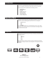
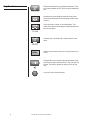
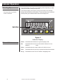
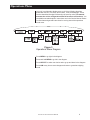
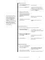
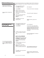
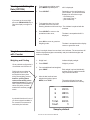
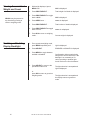
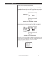
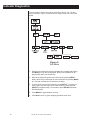
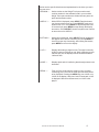
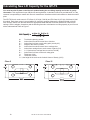
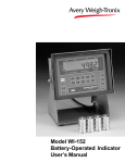
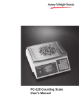
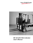
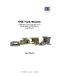
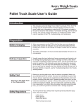
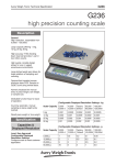
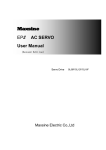
WI-125 for Lift Trucks
User’s Manual
CAUTION
Risk of electrical shock. Do not remove cover. No user serviceable parts inside. Refer servicing to qualified service personnel.
Weigh-Tronix reserves the right to change
specifications at any time.
07/20/05 125LTS_U.P65 PN 29554-0017H e2 Printed in USA
2
WI-125 for Lift Trucks User's Manual
Table of Contents
Introduction ............................................................................................................ 5
Operations Mode ................................................................................................... 5
Keyboard ............................................................................................................... 5
Key Functions .................................................................................................. 6
Entering Numbers with Arrow Keys ................................................................. 7
Indicator Operation ................................................................................................ 8
Powering Up .................................................................................................... 8
Annunciators .................................................................................................... 8
Operations Menu ................................................................................................... 9
Gross/Tare/Net Weighing Operations ........................................................... 10
Gross Weighing ....................................................................................... 10
Net Weighing ........................................................................................... 10
Pushbutton Tare ................................................................................ 10
Entering a Scroll Tare ........................................................................ 11
Clearing the Active Tare .................................................................... 11
Net Weighing Operation .................................................................... 11
ID Number Entry ............................................................................................ 12
Viewing and Setting Time (Option) ................................................................ 12
Viewing and Setting Date (Option) ................................................................ 13
Single Accumulator with Counter .................................................................. 13
Viewing Accumulated Weight and Count ...................................................... 14
Enabling or Disabling Display Backlight ........................................................ 14
Transmitting Data ................................................................................................ 15
Indicator Diagnostics ........................................................................................... 16
Calculating New Lift Capacity for the QTLTS ...................................................... 18
Daily Inspection Checklist for Lift Truck Scale Users .......................................... 20
Pages are numbered consecutively beginning with the cover page.
WI-125 for Lift Trucks User's Manual
3
WI-125 Specifications
Dimensions:
Power:
Display:
Display Rate:
9.37" W x 6.75" H x 3.75" D
(23.8 cm x 17.1 cm x 9.5 cm)
10 to 90 VCD, 300 mA maximum
8 digits, 7-segment LCD, 0.6 inch high with annunciators and backlighting.
One, two or five times per second
Agencies:
NIST Handbook 44, Class III, IIIL, 5,000 divisions COC #92-167.A3
FCC Class A
Accuracy :
Class III, IIIL; 5,000 divisions
Span: ±5.0 ppm/C
Zero: ±.066 uV/C (-10 to 40°C)
Span: ±10 ppm/C
Zero: ±0.13 uV/C (-30 to 60°C)
Linearity:
±0.005% of capacity, maximum
Repeatability:
±0.005% of capacity, maximum
Hysteresis:
Weigh bar drive capacity:
Environment:
Internal Resolution:
A to D conversion rate:
Analog Range:
0.005% of capacity, maximum
Up to four 350 ohm weigh bars.
-10 to 40°C (14 to 104°F) for HB-44 specs
10 to 90% relative humidity
0.5 mV/V = 400,125 counts
30 times per second
-0.14 to +3.5 mV/V
Capacity:
.00001 to 999999, programmable to any number between these limits.
Divisions:
.0001 to 20000, programmable to any division size between these limits.
Push Button Zero Range:
Tare:
Motion Detection Window:
Automatic Zero Tracking:
0 to ±100% of capacity; programmable independent positive and negative limits; unit will not allow
zeroing beyond capacity.
The unit may be configured to have pushbutton tare which can function as a scroll tare register.
Pushbutton tare and scroll tare may tare only positive gross weights up to the capacity of the unit. Scroll
tare allows numeric entry of a tare value using two keys to enter the value.
Programmable from 0 to 999999 divisions, decimal entries are accepted.
Window: Programmable from 0 to 999999 divisions, decimal entries are accepted.
Net Mode
Tracking: May be enabled or disabled.
Rate:
0.2 division per second
Starting Delay:
2 seconds
Linearity:
Angle Compensation:
VIBRATION COMPENSATION
Analog Low Pass Filter:
Software Low Pass Filter:
4
Second order correction provides smooth curve fit through three points--zero, linearity, span.
Compensates for pitch and/or roll out-of-level weighing.
Two section with .10 second time constant for low power analog and .06 second time constant for
standard analog.
One section with .05 second time constant.
WI-125 for Lift Trucks User's Manual
Introduction
The WI-125 is a weight indicator which may be used with Lift Truck Systems. The indicator is powered by a DC power source of 10 to 90 volts.
This set of instructions is divided into the following sections:
• Introduction
• Operations Mode
• Keyboard
• Indicator Operation
• Operations Menu
• Transmitting Data
• Indicator Diagnostics
Operations Mode
Operations mode contains all normal weighing operations. In this mode you
can view or set the following parameters if the unit is so configured:
• pushbutton tare
• time
• date
• backlight
Time, date and backlight can be secured behind a security code. Parameters secured by the code number can be viewed but not changed unless
you enter the security code.
Keyboard
The keyboard consists of 7 keys. Five keys, or buttons, provide all the basic
weighing functions:
• Tare
• Gross/Net
• Zero
• Print
• Units
The other keys are used to access the menus for purposes of accessing
information, testing the indicator, and configuration. The keyboard is shown
in Figure 1.
Figure 1
WI-125 Keyboard
WI-125 for Lift Trucks User's Manual
5
Key Functions
Enters a pushbutton tare in gross/net operation. This
key's factory default is OFF and it must be enabled for
use.
Accesses the gross weighing mode from any other
function and activates the net weighing mode if a tare
is active.
Zeros the scale in gross or net weigh mode. This
button also clears scrolled digits on the display before
they are accepted.
Sends a print command and is used to select menu
items.
Used to access menus and move among choices in a
menu.
Changes the unit of measure during operations mode
and moves a digit inserted with the ↑ key one space to
the left. The factory default for this key is set for lbs
only.
Lets you scroll numerical values.
6
WI-125 for Lift Trucks User's Manual
Entering Numbers with
Arrow Keys
The arrow keys are used to enter numbers. Refer to this section when you
need to enter a number or numbers.
Example: To key in the number 603
Press the ↑ key repeatedly until the 6 appears on the display.
If at any time you enter an
incorrect number, press
CLEAR to delete the number,
then re-key.
Press the ← key once to move the 6 one space to the left.
Press the ↑ key until the 0 appears.
Press the ← key once to move the 60 one space to the left.
Press the ↑ key until 3 appears.
The decimal appears after the 9 as you scroll through the numbers with the
↑ key. After the decimal appears, press the ← key once, then enter the next
digit of your number.
WI-125 for Lift Trucks User's Manual
7
Indicator Operation
Powering Up
No annunciators are lit while
motion is detected.
The unit will power up in gross or net weighing mode, depending on what
mode the unit was in when last turned off.
The indicator display (see Figure 2) tells you the status of the indicator
through the illumination of annunciators. The annunciators are small black
arrows pointing to the different labels around the display face.
Figure 2
Indicator Display
Annunciators
Gross - Illuminates when indicator is in gross weighing mode.
Net -
Illuminates when a tare is in effect and the indicator is in net
weighing
mode.
CZero - Illuminates when the scale is within ±1/4 division of zero.
8
Print -
Illuminates when the print key is pressed and data is transmitted.
lb, kg -
Illuminates the active unit of measure in weighing mode.
WI-125 for Lift Trucks User's Manual
Operations Menu
Your unit is configured to display some or all of the following functions:
pushbutton tare, ID, time, date, accumulator, count, and backlight. These
can be viewed and changed if allowed by the security code. This manual
assumes the unit is configured to allow full access to all functions. You
can disable unneeded options. Instructions are in the Service Manual. Below
is a flowchart and general instructions for moving around the operations
mode menu.
Figure 3
Operations Menu Diagram
Press MENU to go right in the diagram.
Press and hold MENU to go left in the diagram.
Press SELECT to select new choice and to go up and down in the diagram.
Press G/N at any time to save changes and return to gross/net weighing
mode.
WI-125 for Lift Trucks User's Manual
9
Gross/Tare/Net
Weighing Operations
Gross Weighing
To perform gross/net weighing operations, follow these steps:
1. Power up the indicator.
2. If the unit is not in gross mode,
press the G/N key once to get to
gross mode.
3. Make sure the forks of the lift
truck are off the ground and
empty, then press the
ZERO key.
4. Select unit of measure by
pressing the UNITS button.
5. Place weight on the scale.
Indicator powers up in gross or net
mode.
The annunciator illuminates next to
gross. See Figure 2
No weight is displayed and the zero
annunciator illuminates. See Figure
2.
The units annunciator will point to
the chosen unit of measure.
Gross weight is displayed.
Net Weighing
For net weighing operations a tare needs to be entered. A tare can be
entered by two methods: pushbutton tare or entering a numerical value while
in the operations menu.
Factory default configuration is
Tare off.
Pushbutton Tare
1. With the indicator powered up in
gross mode, make sure the forks
of the lift truck are off the ground
and empty, then press the ZERO
key.
2. Place the weight to be tared on
the scale.
3. Press the TARE key on the
indicator.
4. Add more weight to the scale.
5. View the gross weight by
pressing the G/N button.
6. Press the G/N key again to see
net weight.
10
WI-125 for Lift Trucks User's Manual
No weight is displayed and the zero
annunciator illuminates.
The weight of the object is displayed.
The weight is tared, the display
reads zero and the net annunciator
illuminates.
Net weight is displayed.
Gross weight is displayed and the
gross annunciator illuminates.
Net weight is displayed and the net
annunciator illuminates.
Entering a Scroll Tare
1. From gross/net weighing mode,
press the MENU key.
2. Briefly press the SELECT key.
You may view the current or
active tare value at any time
during a weighing process.
From gross or net weighing
mode, press MENU then
SELECT. If a tare value is in
use, it will be displayed. Press
G/N to return to gross/net
weighing mode. Refer to the
Operations Menu and Figure 3
for more details.
3. With the current tare value
displayed, enter a numerical
value for your tare. Refer to the
section Entering Numbers with
Arrow Keys. Then, press the
SELECT key.
4. Press G/N to return to gross/net
weighing mode.
tArE is displayed.
no tArE or the current tare value is
displayed. You can toggle between
no tArE and the current tare value by
pressing the MENU key.
New tare value is displayed, then
tArE is displayed.
Display returns to gross or net
mode.
Clearing the Active Tare
There are two ways to remove the current or active tare weight.
1. Remove all weight from the
scale and press TARE.
Tare register is cleared, scale
returns to gross mode and no weight
is displayed.
2A. With the gross or net annunciator
illuminated, press MENU, then
press CLEAR.
tArE is displayed, then no tArE is
displayed.
2B. Press the G/N key.
Gross weight is displayed and no
tare is active.
Net Weighing Operation
1. After a tare is established, place
the indicator in net mode by
pressing the G/N key.
2. Place material to be weighed in
the tared container on the scale.
WI-125 for Lift Trucks User's Manual
Net annunciator illuminates. Zero
weight will be displayed with the
container on the scale.
Net weight of material is displayed.
11
ID Number Entry
Reference the Operations
Menu section for menu details.
Factory default configuration is
ID off.
You may enter an ID number of up to 8 digits in length. The ID number may
include any combination of the numbers 0 through 9, a dash and a decimal
point.
1. From gross weighing mode,
press MENU repeatedly. . .
id. is displayed.
2. Press SELECT . . .
The current ID number is displayed.
3. With the current ID number
displayed, enter a numerical
value for your ID number using
the keypad.
The new ID number is displayed.
4. After your new ID number has
been displayed, press
SELECT. . .
id. is displayed.
5. Press G/N to return to the
weighing mode.
Viewing and Setting
Time (OPTION)
1. From gross/net weighing mode,
press MENU repeatedly until. . .
2. Press SELECT. . .
3. To set the 12 hour clock, press
the ↑ key to delete the old time
value.
If you enter an incorrect digit,
press the ZERO/CLEAR key to
clear the display one digit at a
time.
Display returns to gross or net
mode.
Hour is displayed.
In the 12 hour clock configuration
you will see time displayed as hours,
minutes and A for A.M. or P for P.M.
(09.40 A). In the 24 hour clock, you
will see hours, minutes and seconds
(09.40.38).
0 A or 0 P is displayed. The A is for
A.M., P for P.M.
Key in the time as hh mm ss.
Refer to the section Entering
Numbers with Arrow Keys. Press
the TARE key to toggle between
AM & PM after entering at least
one digit and before pressing
SELECT.
4. To set the 24 hour clock, key in
time as hh mm ss.
5. After the clock is set, press
SELECT to start the clock and
return to operations mode menu,
Hour is displayed, and the clock
begins at the new time setting.
or
press G/N to return to gross/net
weighing mode.
12
WI-125 for Lift Trucks User's Manual
Display returns to gross/net mode
and the clock begins at the new time
setting.
Viewing and Setting the
Date (OPTION)
If you enter an incorrect digit,
press the ZERO/CLEAR key to
clear the display one digit at a
time.
1. From gross/net weighing mode,
press MENU repeatedly until. . .
2. Press SELECT. . .
dAY is displayed.
Depending on the configuration of
your indicator, you will see the date
displayed in one of three ways:
• month-day-year,
• day-month-year, or
• year-month-day.
3. To change the date, key in the
new data. Refer to the section
Entering Numbers with Arrow Keys. The old date is replaced with the
new date.
4. Press SELECT to return to the
operations mode menu,
The date is accepted and dAY is
displayed.
or
press G/N to return to gross/net
weighing mode.
The date is accepted and the display
returns to gross/net mode.
Single Accumulator
with Counter
There is a single channel accumulator in the indicator. The accumulator will
add the displayed weights automatically and print individual weights and
totals on command.
Weighing and Printing
1. Weigh load. . .
Indicator displays weight.
2. Press PRINT. . .
Weight is printed.
Factory default configuration is
Accumulator and Counter off.
Printing the accumulated
weight and count can be
accomplished at any time
during the weighing process;
however, printing these
values automatically clears
them from memory! So take
care to print the accumulated
values only after you have
made all the necessary weighments.
A print/add function will occur if
you have autoprint enabled or
if a remote Print command is
received by the indicator.
3. For each additional load weighed,
press PRINT. . .
Each weight is printed individually
and the weight is totalled automatically within the indicator.
4. After the last load has been
weighed and printed, press
MENU, then TARE. . .
G
G
G
Total
Count
The total weight and count are
printed and cleared from memory.
210 lb
200 lb
200 lb
610 lb
3
Sample printout
WI-125 for Lift Trucks User's Manual
13
Viewing Accumulated
Weight and Count
GROSS may be pressed at
any time during viewing to
return to weighing mode.
Enabling or Disabling
Display Backlight
1. With weight displayed, press
MENU until. . .
ACC is displayed.
2. Press PRINT/SELECT. . .
Total weight of all loads is displayed.
3. Press PRINT/SELECT to toggle
back to ACC. . .
ACC is displayed.
4. Press MENU once. . .
count is displayed.
5. Press PRINT/SELECT. . .
Total number of loads is displayed.
6. Press PRINT/SELECT to toggle
back to count. . .
count is redisplayed.
7. Press G/N to return to weighing
mode. . .
Current weight is displayed.
1. From gross/net weighing mode,
press MENU repeatedly until . . .
Light is displayed.
2. Press SELECT.
ENABLED or diSAbLEd is displayed.
3. Press MENU to toggle between
enabled or disabled.
4. Press SELECT to return to the
operations mode menu
Configuration choices made during
setup of this unit will determine if the
backlight is on constantly or if it
varies according to ambient light
levels. Refer to the Service Manual.
The light selection is accepted and
Light is displayed.
or
press G/N to return to gross/net
weighing mode.
14
WI-125 for Lift Trucks User's Manual
The light selection is accepted and
the display returns to gross/net
mode.
Transmitting Data
RS-232 output is available for data transmission.
If your indicator has the serial option installed and the indicator is configured
to allow printing from the gross/net weighing mode, press the PRINT key.
The PRINT annunciator (See Figure 2) will illuminate while data is transmitted to the printer. A default printout will list displayed weight only (see Figure
4).
Figure 4
Sample WI-125 Default Printout
You can layout your printout for your specific need. Below is a sample of
another printout. See the print layout instructions in the Service Manual.
Figure 5
Possible Print Configuration
An enquire code can be sent to the WI-125. This will prompt the indicator to send
a standard printout. The default enquire code number is an ASCII decimal 005. This
number can be changed in configuration. See your Service Manual.
The default settings for serial output are:
Busy - Disabled
Baud - 1200
Parity - None
Stop bits - 1
Data bits - 8
WI-125 for Lift Trucks User's Manual
15
Indicator Diagnostics
The test mode is used to test various functions of the WI-125. The test
menu is shown in Figure 6. Instructions for using the test menu are found
below.
Figure 6
Test Menu
1. Enter the test mode from gross/net operation by pressing and holding
the MENU key until tESt is displayed. SEALEd or unSEALEd is displayed briefly while you hold the key.
2. Move to the right through the menu selections by pressing MENU
briefly. Move to the left through the menu selections by pressing MENU
for 1 second or hold down for continuous scrolling.
3. To move down a level in the hierarchy, press SELECT. Anytime you
wish to get to the next higher level in the hierarchy, press and hold
SELECT for approximately 1.5 seconds or press SELECT whenever
End is displayed.
4. Press MENU to toggle between choices.
5. Press G/N to return to gross weighing operation at any time.
16
WI-125 for Lift Trucks User's Manual
Below are the specific directions and explanations for the items you see in
the test menu.
VERSION —
Under version are the Weigh-Tronix part number and
revision number for the software found in your machine.
Weigh-Tronix part numbers are divided into two parts: the
prefix and the dash number.
DISPLAY —
With diSPLAY displayed, press SELECT and the bottom
row of annunciators turns on. Press SELECT again and a
dynamic test is run. Press MENU to stop the dynamic test
or consecutively press MENU to step through the display
test routine. Press SELECT when the dynamic test is active
to return the unit to diSPLAY.
BUTTONS —
With buttonS displayed, press SELECT and an underscore
will appear on the screen. Press any key except MENU to
check for proper key functioning. After testing the buttons,
press MENU to return to the display.
A to D —
Displays the analog to digital counts. The span is normally
20,000 counts per millivolt per volt. With a calibrator at zero
millivolts per volt, the displayed value should be between
-200 and +200.
ANGLE —
Displays pitch and roll confirming that the angle sensors are
functional.
SERIAL —
Tells you if the serial output is ready or busy. A jumper
connecting pins 4 and 8 of the serial port will cause rEAdY
to be displayed. Pressing the MENU key puts LOOP or no
LOOP on the display. With pins 2 and 3 connected, LOOP
is displayed. With them disconnected, no LOOP is displayed.
WI-125 for Lift Trucks User's Manual
17
Calculating New Lift Capacity for the QTLTS
You must have the ID plate on the lift truck updated stating the new lifting capacity and center of gravity
information. This requirement is per OSHA rules and regulations. A calculation formula is provided below. It is the
customer’s responsibility to contact their lift truck manufacturer / distributor with this information to obtain the new ID
plate.
The QTLTS lift truck scale comes in ITA Class II (16" high, 5,000 lb) and ITA Class III (20" high, 5,000 and 10,000
lb) models. Each class comes in several widths for cleat type carriages. Measure the height and width of the lift
truck carriage. Select from the table below the appropriate width that best meets the dimensions of the lift truck
carriage. Use the weights, dimensions and the following formula to calculate the net lifting capacity of your lift truck
with a scale attached. Refer to Figure 7.
A=
Truck basic capacity, pounds
B=
Inches from front wheel center line to fork face
C=
Inches from fork face to truck rating point (usually 24")
D=
Weight of the scale in pounds
E=
Inches from front wheel center line to carriage face
F=
Inches from carriage face to scale center of gravity (CG)
G=
J + K (Inches from carriage face to rear face of load)
H=
Inches from fork face to new truck rating point
J=
Thickness of fork
K=
Thickness of scale
L = ½ the height of the scale or the Vertical Center of Gravity (VCG)
Class II
18
Class III
WI-125 for Lift Trucks User's Manual
Class II 5,000 lb Models
Scale P/N
Width
48196-0094
48196-0011
48196-0029
48196-0102
48196-0037
48196-0110
48196-0128
48196-0045
30.0"
32.0"
34.0"
36.0"
37.0"
38.0"
40.0"
42.0"
Weight “D”
373
381
389
410
413
418
438
446
lb
lb
lb
lb
lb
lb
lb
lb
DIM “F”
DIM “K
2.0"
2.0"
2.0"
2.0"
2.0"
2.0"
2.0"
2.0"
4.0
4.0
4.0
4.0
4.0
4.0
4.0
4.0
Class III 5,000 lb Models
Scale P/N
Width
51856-0016
51856-0024
51856-0032
51856-0057
51856-0073
51856-0099
51856-0115
51856-0131
36.0"
37.0"
38.0"
40.0"
42.0"
44.0"
46.0"
48.0"
Weight “D”
DIM “F”
DIM “K”
520
530
540
580
635
685
700
720
2.00"
2.00"
2.00"
2.00"
2.00"
2.00"
2.00"
2.00"
4.00"
4.00"
4.00"
4.00"
4.00"
4.00"
4.00"
4.00"
Class III 10,000 lb Models
Scale P/N
Width
Weight “D”
DIM “F”
DIM “K”
51857-0031
51857-0056
51857-0072
51857-0106
51857-0114
51857-0155
51857-0197
51857-0239
40.0"
42.0"
44.0"
47.0"
48.0"
52.0"
56.0"
60.0"
725
780
795
855
865
935
1005
1030
2.75"
2.75"
2.75"
2.75"
2.75"
2.75"
2.75"
2.75"
5.50"
5.50"
5.50"
5.50"
5.50"
5.50"
5.50"
5.50"
Lift truck with no scale
Lift truck with scale
Figure 7
Recalculating Lift Truck Capacity
WI-125 for Lift Trucks User's Manual
19
Daily Inspection Checklist For Lift Truck Scale Users
❑
❑
❑
❑
❑
❑
❑
❑
❑
❑
❑
❑
❑
Check scale carriage for loose, worn, bent, or broken components.
Inspect forks for damage.
Check locking pins on forks for proper function.
Inspect cables from the junction box to Weigh Bars for wear.
Inspect retractable cable for pinched, rubbed, stretched, or damaged areas.
Inspect power cable for nicks or cuts.
Make sure power cable is routed out of harms way. Fasten periodically to eliminate potential problems.
Tighten cable connections at indicator and summing box if necessary.
Inspect cable clamps and cable ties to be sure all cable attachments are secure.
Inspect digital indicator mounting bracket, isolation mounts and hardware for loose or cracked parts.
Check to make sure the junction box cover/shield is fastened.
Tighten bottom clamps on scale carriage if necessary. Raise carriage and visually inspect.
Check and adjust the lift chain so the heel of the forks have ½" to 1" of clearance from the floor when the
carriage is down and the mast is vertical.
20
WI-125 for Lift Trucks User's Manual
WI-125 for Lift Trucks User's Manual
21
22
WI-125 for Lift Trucks User's Manual
Declaration of Conformance to SMA Standard
Year of Declaration 2002
Production Meets Type
®*
We the manufacturer of
Model
Type
Certificate and Number
Issued by
WI-125
Digital Electronic Indicator
NTEP CC 92-167A4
NCWM
Declare in our responsibility the conformance of the above listed models and types to the
mentioned certificates and the requirements of the SMA standard.
This declaration becomes valid when the SMA Conformance Logo, having our name or trademark is applied to the device or its accompanying documentation.
* SMA PRODUCTION MEETS TYPE DEVICE MANUFACTURER Conformance Logo and Design are a registered
trademark of the Scale Manufacturers Association
WI-125 for Lift Trucks User's Manual
23
Avery Weigh-Tronix USA
1000 Armstrong Dr.
Fairmont, MN 56031 USA
Telephone: 507-238-4461
Facsimile: 507-238-4195
e-mail: [email protected]
www.wtxweb.com
Avery Weigh-Tronix UK
Foundry Lane
Smethwick, West Midlands
England B66 2LP
Tel: +44 870 90 34343
Fax: +44 121 224 8183
Email: [email protected]
Web site:www.averyweigh-tronix.com
Weigh Bar ® is a registered trademark
of Avery Weigh-Tronix and may be
registered in certain jurisdictions.
All brands and product names used
within this document are trademarks
or registered trademarks of their respective holders.
Avery Weigh-Tronix Canada, ULC
217 Brunswick Boulevard
Pointe Claire, QC H9R 4R7 Canada
Telephone: 514-695-0380
Toll free: 800-561-9461
Facsimile: 514-695-6820
www.weigh-tronix.ca