1
A11403-AB
March 2004
®
IMMAGE® 800
Immunochemistry System
For In Vitro Diagnostic Use
Operations Manual
EC REP
Beckman Coulter Ireland, Inc.
Mervue Business Park,
Mervue Galway,
Ireland 353 91 774068
© Copyright 2004 Beckman Coulter, Inc.
BECKMAN COULTER, INC. • 4300 N. Harbor Blvd., Fullerton, CA U.S.A. 92835
TABLE OF CONTENTS
SAFETY NOTICE
CHAPTER 1
General Information/Precautions and Hazards ................................................ 1-1
CHAPTER 2
System Description .......................................................................................... 2-1
CHAPTER 3
Theory of Operations ....................................................................................... 3-1
CHAPTER 4
System Power On/Off ...................................................................................... 4-1
CHAPTER 5
System Setup .................................................................................................... 5-1
CHAPTER 6
Reagents/Calibration ........................................................................................ 6-1
CHAPTER 7
Sample Programming ...................................................................................... 7-1
CHAPTER 8
Results Recall .................................................................................................. 8-1
CHAPTER 9
Quality Control ................................................................................................ 9-1
CHAPTER 10 Utilities ........................................................................................................... 10-1
CHAPTER 11 System Status/Instrument Commands ........................................................... 11-1
APPENDIX A Part Number List ............................................................................................. A-1
APPENDIX B Instrument Codes .............................................................................................B-1
APPENDIX C Reports .............................................................................................................C-1
GLOSSARY
INDEX
IMMAGE 800 Operations Manual A11403
March 2004
Table of Contents
Page 1 of 1
Introduction
Safety Notice
Introduction
This safety notice summarizes information basic to the safe operation of the
IMMAGE® 800 Immunochemistry System described in this manual. The
international symbol displayed above is a reminder that all safety instructions should
be read and understood before installation, operation, maintenance, or repair of this
instrument. When you see the symbol on other pages, pay special attention to the
safety information presented. Observance of safety precautions will also help to avoid
actions that could damage or adversely affect the performance of the instrument.
Other symbols may also be displayed on the equipment. These are reproduced and
described in the Operating Precautions and Hazards section.
Safety During Installation and/or Maintenance
This instrument is designed to be installed by a Beckman Coulter Field Service
representative. Installation by anyone other than authorized Beckman Coulter
personnel invalidates any warranty covering the instrument.
Any servicing of this equipment that requires removal of any covers can expose parts
which involve the risk of electric shock or personal injury. Make sure that the power
switch is turned OFF and that the instrument is disconnected from the main power
source. Refer such maintenance to qualified service personnel.
Electrical Safety
• To reduce the risk of electrical shock, this instrument uses a three-wire electrical
cord and plug to connect to earth-ground. Make sure that the matching wall outlet
receptacle is properly wired and earth-grounded.
• Never remove or install any circuit board, connect or disconnect any plug or cable,
while the power is ON. Always use the antistatic wrist strap located in the electronic
board compartment when removing or installing any circuit board.
• Do not place containers holding liquid on top of the instrument. If a spill occurs,
liquid may get into the instrument and damage electrical or mechanical components.
Safety Against Risk of Fire
Fuses protect certain electrical circuits within this instrument against overcurrent
conditions. For continued protection against the risk of fire, replace only with the
same type and rating specified.
IMMAGE 800 Operations Manual A11403
March 2004
Safety Notice
Page 1 of 2
Mechanical Safety
Mechanical Safety
For safe operation of the equipment, observe the following:
• Operate the system with reagent door and covers and shields in place.
• During power up, routine operation, and diagnostic procedures, keep hands and/or
foreign objects out of the path of the carousels and probes.
• Do not attempt to clean around the carousels and probes while they are in motion.
Wait until the instrument is in "standby" to perform cleaning procedure.
Chemical and Biological Safety
Normal operation may involve the use of solutions and test samples that are
pathogenic or infectious. Observe all laboratory policies or procedures which pertain
to the handling of these materials.
• The reagents and other chemical preparations used with the system will not
normally cause adverse reactions; however, those persons with sensitive skin should
wear protective gloves before attempting to work with reagents and other chemical
preparations.
• Do not handle sample or solutions without proper protection. Body fluids and other
infectious samples must be handled according to good laboratory practice to prevent
spread of disease.
• When performing maintenance, service, or troubleshooting on elements of the
system that have contacted sera or other biological fluids, observe standard
laboratory precautions. It is always necessary to wash your hands thoroughly after
performing any routine maintenance.
Dispose of all waste solutions according to appropriate environmental health and
safety guidelines.
Safety Notice
Page 2 of 2
IMMAGE 800 Operations Manual A11403
March 2004
1
CHAPTER 1 General Information/Precautions and Hazards
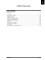
Table of Contents
General Information/Precautions and Hazards ........................................................................... 1-2
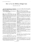
Introduction ............................................................................................................................. 1-2
How to Use This Manual ........................................................................................................ 1-3
Warranty and Service Policy Information .............................................................................. 1-5
Precautions .............................................................................................................................. 1-6
Hazards .................................................................................................................................... 1-7
Symbols and Labels ................................................................................................................ 1-9
IMMAGE 800 Operations Manual A11403
March 2004
General Information/Precautions and Hazards
Page 1-1
Introduction
Intended Use
General Information/Precautions and Hazards
Introduction
Intended Use
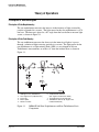
The Beckman Coulter IMMAGE® 800 Immunochemistry System is a fully automated,
computer controlled, bench-top analyzer designed for the in vitro quantitation of
biological fluid components and therapeutic drugs. The system methodologies are rate
turbidimetry and rate nephelometry.
The IMMAGE 800 is a high throughput, random access analyzer that features bar code
identification of samples and reagents to perform sample testing. It automatically
dilutes the samples and delivers them to the reaction cuvette along with other reaction
constituents. The system analyzes up to 72 samples per run with up to 24 analytes per
sample.
General Information/Precautions and Hazards
Page 1-2
IMMAGE 800 Operations Manual A11403
March 2004
How to Use This Manual
Scope of This Manual
How to Use This Manual
Scope of This Manual
This manual provides information on the operation of the IMMAGE 800. Diagnostic
interpretation or the clinical significance of the assay results provided by the system
are not discussed in this manual. Typical and actual results are shown only to
demonstrate the operating procedures, parameters, and characteristics of the system.
IMMAGE Chemistry Information Manual
This manual should be used in conjunction with the IMMAGE Immunochemistry
Systems Chemistry Information Manual which contains specific chemistry
information for the full range of analytes available on the IMMAGE 800.
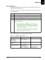
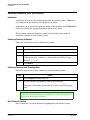
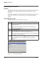
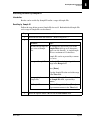
Manual Conventions
The IMMAGE 800 Immunochemistry System Operations Manual uses the following
printed and visual cues to guide the user in how to respond to printed directions.
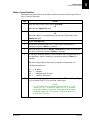
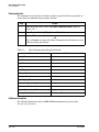
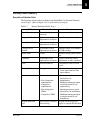
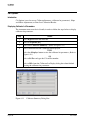
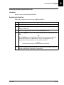
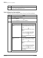
Table 1.1
IMMAGE 800 Conventions
Convention
Description
Icon Buttons
Icon buttons are in bold with one letter underlined. The
underline indicates which letter to press in combination
with the Alt key to select the icon button from the
keyboard.
Function Buttons [F1]
Function buttons are in bold with the corresponding
function key in square brackets ( [ ] ).
<Buttons>
The "less than" (<) and "greater than" (>) symbols enclose
a button’s name in bold.
Options button <▼>
The "less than" (<) and "greater than" (>) symbols enclose
a black triangle, preceded by the phrase "options button",
all in bold.
Text field
Names of text fields are followed by the word "field", all
in bold.
[X], [ → ] or [Tab]
Keyboard keys are in bold and enclosed by square
brackets ( [ ] ).
[Alt + X]
Combination keys are in bold and enclosed by square
brackets ( [ ] ) with a plus (+) between each key.
Manual Format
Information in this manual is presented in modular units. Each unit of information is
described by a brief title in the left margin.
Many units consist of a table which presents a procedure, process, or description.
IMMAGE 800 Operations Manual A11403
March 2004
General Information/Precautions and Hazards
Page 1-3
1
How to Use This Manual
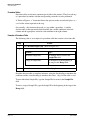
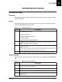
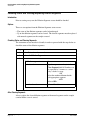
Procedure Tables
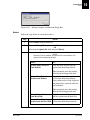
Procedure Tables
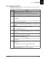
Procedure tables are the most common type of table in this manual. They list each step
of a procedure by number with the corresponding action that is to be performed.
A "Refer to Figure x.x." instruction directs the operator to the screen that displays as a
result of the action requested in the step.
Occasionally, a decision must be made at a step within a procedure. A smaller
decision table is then presented which describes the variable conditions in the left
column and the appropriate action for each condition in the right column.
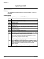
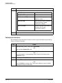
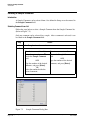
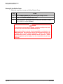
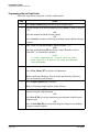
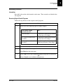
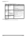
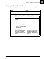
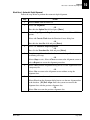
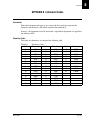
Example of Procedure Table
The following table is an example of a procedure table that contains a decision table.
Step
1
Action
Select Rerun Samples [F6]. (Refer to Figure x.x.)
2
3
To enter...
type...
individual Sample IDs,
the Sample IDs for rerun in the
Sample IDs field.
a range of Sample IDs,
the Sample ID at the beginning of
the range in the Range field.
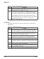
Select a button from the bottom of the dialog box.
Read the decision table as complete sentences, using the first heading to introduce the
condition and the second heading to introduce the action. Step 2 of the table is read:
To enter individual Sample IDs, type the Sample IDs for rerun in the Sample IDs
field.
To enter a range of Sample IDs, type the Sample ID at the beginning of the range in the
Range field.
General Information/Precautions and Hazards
Page 1-4
IMMAGE 800 Operations Manual A11403
March 2004
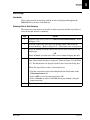
Warranty and Service Policy Information
Warranty Policy
Warranty and Service Policy Information
Warranty Policy
The IMMAGE 800 Immunochemistry System is covered by and subject to the
exceptions of the standard warranty enclosed with each system. Failure to operate the
system in accordance with this manual voids the warranty.
Service Information
If any fault develops in the system, call the Beckman Coulter Clinical Support Center.
Give full details of the difficulty. Be sure to have the model and serial number (located
on the lower right side of the instrument near the front.)
For USA and Canadian customers only:
Call your local Beckman Coulter office toll-free from anywhere in the continental
United States, Alaska, Hawaii, and Canada at (800) 854-3633.
For customers outside the USA and Canada:
Call the nearest Beckman Coulter Field Service Office.
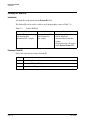
Responsibility During the Warranty Period
The user is responsible for the routine preventive maintenance procedures described in
the maintenance section of this manual. Repairs arising from failure to perform these
maintenance procedures at the indicated time intervals will be made at the user’s
expense.
Shipping Damage
Each IMMAGE 800 System is carefully examined and checked by Beckman Coulter
before it is shipped. When you receive your new IMMAGE 800 System, visually
inspect the shipping container for any possible damage. If there is damage, notify the
Beckman Coulter Service Representative before his/her arrival at your facility to
install your system.
If no damage is found to the shipping container, the Beckman Service Representative
will supervise the unpacking of your system. If it is damaged in any way, the customer
should file a claim with the carrier. If no damage is found, a visual and operational
check of your system will be performed.
IMMAGE 800 Operations Manual A11403
March 2004
General Information/Precautions and Hazards
Page 1-5
1
Precautions
Introduction
Precautions
Introduction
The operational precautions below enable the user to avoid those actions which could
result in an invalid quantitative determination.
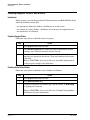
Proper Handling of Diskettes
The 3.5 inch floppy diskettes require special handling to prevent damage.
• Do not store or place a diskette near electrical motors, power supplies, or generators.
• Do not store or place a diskette near magnets or a magnetic field.
Proper Handling of Compact Disks
Compact disks (CD-ROMs) require special handling to prevent damage.
• Do not place a CD-ROM in direct sunlight or excessive heat or humidity.
• Hold a CD-ROM by the edges.
• Replace a CD-ROM in its case after use.
Sample Volumes
Sample containers must contain an adequate volume of test specimen to ensure
accurate aspiration. Refer to the IMMAGE Immunochemistry Systems Chemistry
Information Manual and the Sampling Template for information regarding volume
requirements.
CAUTION
Use extreme care when removing bar coded or labeled glass sample tubes from the
IMMAGE 800 sample racks to avoid breakage. Rotating the tube slightly while
pushing from the bottom of the tube may make removal easier.
General Information/Precautions and Hazards
Page 1-6
IMMAGE 800 Operations Manual A11403
March 2004
Hazards
Introduction
Hazards
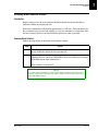
Introduction
The following hazards are identified to ensure maximum safety of the user.
Booting Up
Close reagent and sample carousel covers and keep clear of all mechanical assemblies
when booting up the system.
Three-pronged Power Plugs
The three-pronged power plug from all system components of the IMMAGE 800
Immunochemistry System must be connected to a three-wire grounded power source.
• Do not use an adapter to connect the power plug to a two-pronged outlet.
• If the electrical outlet will not accept the three-pronged plug, notify qualified
maintenance personnel; they will supply the required electrical ground.
DO NOT UNDER ANY CIRCUMSTANCES OPERATE THE SYSTEM UNTIL AN
ELECTRICAL GROUND IS PROVIDED AND THE POWER CORD IS PROPERLY
CONNECTED TO GROUND.
Emergency Stop
Turn the instrument main power switch off if the stop button on the screen is
unavailable, and the instrument must be stopped immediately.
Cranes
Keep clear of both cranes while the instrument is running.
Covers
Keep all covers and shields in place while the instrument is running.
Adding Samples to an Operating Instrument
The instrument status must be in Standby when adding or changing reagents, buffers,
diluents, or dilution segments. The instrument status must be in Standby or PausingOK to load samples when adding or removing samples. Keep reagent and sample
carousel covers closed while the instrument is running.
Pausing the System to Load Samples
If you pause the system to load or remove samples while the system is running, DO
NOT load or remove samples until the OK to load samples message appears on the
screen. Failure to comply may cause personal injury.
IMMAGE 800 Operations Manual A11403
March 2004
General Information/Precautions and Hazards
Page 1-7
1
Hazards
Replacing Mechanical or Electrical Parts
Replacing Mechanical or Electrical Parts
Before replacing any defective mechanical or electrical part in the system, confirm that
the power to the system is turned off.
Bar Code Readers
DO NOT tamper with or remove the housing of any bar code reader.
Disposal of Waste Liquids
All waste liquids from the IMMAGE 800 Immunochemistry System should be
disposed of in an approved method for handling biohazardous material.
Biological Samples
Observe all laboratory policies or procedures pertaining to the handling of biological
samples that may contain pathogens.
Preservatives
Sodium azide preservative may form explosive compounds in metal drain lines. See
National Institute for Occupational Safety and Health bulletin: Explosive Azide
Hazards (8/16/76).
Incineration of used reagent cartridges may produce toxic fumes.
General Information/Precautions and Hazards
Page 1-8
IMMAGE 800 Operations Manual A11403
March 2004
Symbols and Labels
Introduction
Symbols and Labels
Introduction
The following list of symbols and labels is used on the IMMAGE 800
Immunochemistry System. The symbols are affixed to the appropriate components of
the system as described briefly below.
Instrument or Uninterruptible Power Supply (UPS) Power Switch, ON
This symbol is located on the instrument and the UPS main power switches. When the
portion of the switch that displays this symbol is depressed, the instrument is ON.
Instrument or UPS Power Switch ON
Instrument or UPS Power Switch, OFF
This symbol is also located on the instrument and the UPS main power switches.
When the portion of the switch that displays this symbol is depressed, the instrument is
OFF.
Instrument or UPS Power Switch OFF
Computer Power Switch
This symbol is located above the computer power button. A green light indicates the
power to the computer is ON.
Computer Power Switch
IMMAGE 800 Operations Manual A11403
March 2004
General Information/Precautions and Hazards
Page 1-9
1
Symbols and Labels
Monitor Power Switch
Monitor Power Switch
This symbol is located on the monitor power button. A green light indicates the power
to the monitor is ON.
Monitor Power Switch
Printer Power Switch
This symbol is located beside the printer power button. A green light indicates the
power to the printer is ON.
Printer Power Switch
Connection Between Computer and Mouse
This symbol is located beside the connection between the computer and the mouse.
Computer - Mouse Connection
Connection Between Computer and Keyboard
This symbol is located beside the connection between the computer and the keyboard.
Computer - Keyboard Connection
Connection Between Computer and Printer
This text is located next to the connection between the computer and the printer.
Parallel
General Information/Precautions and Hazards
Page 1-10
IMMAGE 800 Operations Manual A11403
March 2004
Symbols and Labels
Connection Between Computer and Monitor
Connection Between Computer and Monitor
This symbol is located beside the connection between the computer and the monitor.
Computer - Monitor Connection
High Voltage - Electric Shock Risk
This symbol indicates high voltage or risk of electric shock.
High Voltage - Electric Shock Risk
Read Manual
This symbol cautions that the manual should be read before using the system.
Read Manual
General Biohazard Caution
This symbol is the international symbol for biohazardous material.
Biohazard Label
IMMAGE 800 Operations Manual A11403
March 2004
General Information/Precautions and Hazards
Page 1-11
1
Symbols and Labels
Caution Biohazard
Caution Biohazard
This cautionary label is located between the sample and reagent carousels. Operate
the system with all covers in place.
Caution Biohazard Label
Bar Code Caution
This label is placed on the cover of any laser-based bar code reader. Do not stare into
laser light beam when cover is open or removed.
Bar Code Caution Label
Laser
This label is placed near any opening through which a bar code reading beam emits.
Avoid exposure to laser light emitted from the opening.
Laser Caution Label
Class II Laser Caution
This cautionary label is located between the sample and reagent carousels. Do not
stare into laser light beam.
Class II Laser Caution Label
General Information/Precautions and Hazards
Page 1-12
IMMAGE 800 Operations Manual A11403
March 2004
Symbols and Labels
Class III B Laser Caution
Class III B Laser Caution
This cautionary label is located at the top of the optics module. Avoid direct exposure
to laser light beam.
A010648L.EPS
Class III B Laser Caution Label
Reagent Compartment Cover Notice
This label is located on the reagent compartment cover. The instrument will stop if the
cover is opened.
A010647L.EPS
Reagent Compartment Cover Label
IMMAGE 800 Operations Manual A11403
March 2004
General Information/Precautions and Hazards
Page 1-13
1
2
CHAPTER 2 System Description
Table of Contents
Hardware Components ............................................................................................................... 2-2
Overview ................................................................................................................................. 2-2
Instrument ............................................................................................................................... 2-3
Reagent Compartment ............................................................................................................. 2-4
Reagent Crane ......................................................................................................................... 2-6
Reaction Module ..................................................................................................................... 2-8
Sample Carousel ................................................................................................................... 2-10
Sample Crane ........................................................................................................................ 2-12
Upper Instrument Subsystems .............................................................................................. 2-14
Wash Solution Box and Waste Container ............................................................................. 2-17
Racks ..................................................................................................................................... 2-19
Computer ............................................................................................................................... 2-21
Printer .................................................................................................................................... 2-25
Software Overview ................................................................................................................... 2-26
Overview ............................................................................................................................... 2-26
Screen Format ....................................................................................................................... 2-27
Text Fields ............................................................................................................................. 2-30
Buttons .................................................................................................................................. 2-31
Toggle Buttons ...................................................................................................................... 2-32
Check Boxes ......................................................................................................................... 2-33
Performing Software Functions ............................................................................................ 2-34
Selecting vs. Choosing .......................................................................................................... 2-36
Dialog Boxes ......................................................................................................................... 2-37
Deleting Data From a Text Field and Printing Data from a Screen ...................................... 2-38
Page Up/Page Down ............................................................................................................. 2-39
Program Structure ................................................................................................................. 2-40
Sample Programming Overview ........................................................................................... 2-45
System Specifications and Characteristics ............................................................................... 2-46
Instrument Specifications ...................................................................................................... 2-46
Peripheral Devices Specifications ........................................................................................ 2-48
Sample Container Information .................................................................................................. 2-49
Sample Containers Allowed .................................................................................................. 2-49
Bar Code Types and Options ................................................................................................ 2-50
Bar Code Label Specifications .............................................................................................. 2-52
Applying Bar Code Labels .................................................................................................... 2-54
Sample Volume ..................................................................................................................... 2-55
Loading Tubes Into Racks .................................................................................................... 2-56
Instrument Operation Overview .............................................................................................. 2-57
Instrument Operation ............................................................................................................ 2-57
IMMAGE 800 Operations Manual A11403
March 2004
System Description
Page 2-1
Overview
Introduction
Hardware Components
Overview
Introduction
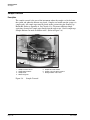
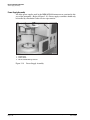
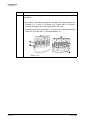
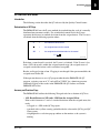
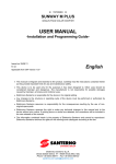
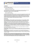
The IMMAGE® 800 Immunochemistry System is a bench-top analyzer composed of
the IMMAGE 800 instrument, computer and printer. (Refer to Figure 2.1.) The
system is shipped complete for installation. The system will be installed by a
Beckman Coulter Representative.
1
2
3
A011408P.EPS
1. Instrument
2. Computer
3. Printer
Figure 2.1
System Description
Page 2-2
The IMMAGE 800 Immunochemistry System
IMMAGE 800 Operations Manual A11403
March 2004
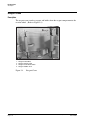
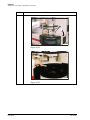
Instrument
Description
Instrument
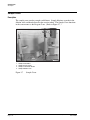
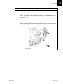
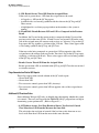
Description
The IMMAGE 800 instrument is the analytical unit where the samples and reagents
are loaded and where the chemical reactions take place.
(Refer to Figure 2.2.)
6
1
5
2
3
4
A011409P.EPS
1. Reagent Compartment
2. Reagent Crane
3. Reaction Module
Figure 2.2
4. Sample Carousel
5. Sample Crane
6. Upper Instrument Subsystems
IMMAGE 800 Instrument
IMMAGE 800 Operations Manual A11403
March 2004
System Description
Page 2-3
2
Reagent Compartment
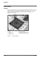
Description
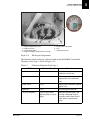
Reagent Compartment
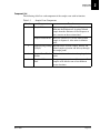
Description
The reagent compartment is the area of the instrument where the removable reagent
carousel is stored. The temperature of the compartment is maintained at
approximately 15°C. (Refer to System Specifications and Characteristics,
"Temperature and Humidity" in this chapter.)
Reaction buffer bottles are placed in the center of the reagent compartment. The
bottles are maintained at room temperature. (Refer to Figure 2.3.)
B
7
6
A
1
2
3
4
5
A011410P.EPS
1.
2.
3.
4.
Reagent Compartment Cover
Reagent Carousel
Reaction Buffer Bottle
Reagent Cartridges (Compartments A and B)
Figure 2.3
5. Reagent Bar Code Reader
6. Fans
7. Temperature Sensor
The Reagent Compartment
NOTICE
The instrument will stop if the reagent compartment cover is opened.
System Description
Page 2-4
IMMAGE 800 Operations Manual A11403
March 2004
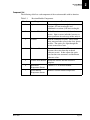
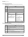
Reagent Compartment
Component List
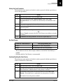
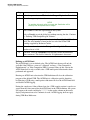
Component List
The following table lists each component of the reagent compartment with its
function.
Table 2.1
Reagent Compartment Components
Number
Component
Function
1
Reagent Compartment Necessary to maintain temperature within
Cover
compartment.
2
Reagent Carousel
Holds up to 24 reagent cartridges and 4 reaction
buffer bottles.
3
Reaction Buffer
Bottles
Contain reaction buffers.
4
Bar Coded Reagent
Cartridges
Contain chemistry specific reagent including
(where applicable):
•
•
•
•
•
Reagent
AGXS (antigen excess) Solution
Co-reagent
Conjugate
Evaporation Caps
The cartridges are bar coded to allow for
instrument identification of each cartridge.
5
Reagent Bar Code
Reader
Reads bar codes on reagent cartridges.
6
Fans
Circulate cool air in reagent compartment.
7
Peltier Temperature
Sensor
Helps control 15°C in reagent compartment.
IMMAGE 800 Operations Manual A11403
March 2004
System Description
Page 2-5
2
Reagent Crane
Description
Reagent Crane
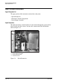
Description
The reagent crane transfers reagents and buffers from the reagent compartment to the
reaction wheel. (Refer to Figure 2.4.)
1.
2.
3.
4.
Reagent Probe/Mixer
Reagent Syringe Pump
Reagent Crane Wash Station
Reagent Addition Ports
Figure 2.4
System Description
Page 2-6
Reagent Crane
IMMAGE 800 Operations Manual A11403
March 2004
Reagent Crane
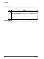
Component List
Component List
The following table lists each component of the reagent crane with its function.
Table 2.2
Number
1
Reagent Crane Components
Component
Reagent Probe
Function
Aspirates reagents and buffer from the reagent
compartment and dispenses them into a cuvette
on the reaction wheel.
Reagent Paddle Mixer Mixes the contents of a cuvette after reagent or
buffer has been dispensed.
2
Reagent Syringe
Pump (500 µL)
Mechanism for accurate reagent and buffer
aspiration and delivery through the reagent
probe.
3
Reagent Crane Wash
Station
Washes interior and exterior of reagent probe/
mixer.
4
Reagent Addition
Ports
Two openings in reaction module cover to allow
reagents to be added to one of two different
cuvette locations.
IMMAGE 800 Operations Manual A11403
March 2004
System Description
Page 2-7
2
Reaction Module
Description
Reaction Module
Description
The reaction module is the area of the instrument where the reaction takes place. The
temperature of the reaction module is maintained at approximately 37°C. (Refer to
Figure 2.5 and System Specifications and Characteristics, "Temperature and
Humidity" in this chapter.)
1.
2.
3.
4.
Optics
Reaction Wheel
Cuvette
Reference Cuvette
Figure 2.5
System Description
Page 2-8
5. Cuvette Wash Station
6. Heat Block Temperature Sensor
7. Status Monitor Temperature Sensor
Reaction Module
IMMAGE 800 Operations Manual A11403
March 2004
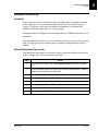
Reaction Module
Component List
Component List
The following table lists each component of the reaction module with its function.
Table 2.3
Number
Reaction Module Components
Component
Function
1
Optics
Measures light scatter in nephelometric
reactions (670 nm wavelength) and
turbidimetric reactions (940 nm wavelength).
2
Reaction Wheel
Holds 39 reaction cuvettes and the reference
cuvette. Spins to move individual cuvettes to
correct positions for each stage of the analysis.
3
Cuvettes
Hold the combined reactants. The reaction
being measured takes place in the clear, plastic
cuvettes. The optics pass light through the
cuvette to measure scatter.
4
Reference Cuvette
Has a known scatter value. The instrument
measures the scatter from the on-board
reference cuvette. It then adjusts the optics
based on these measurements and the known
reference values.
5
Cuvette Wash Station Washes the cuvette after the reaction is
complete.
6
Heat Block
Temperature Sensor
Controls 37°C in reaction module.
7
Status Monitor
Temperature Sensor
Monitors reaction module temperature.
IMMAGE 800 Operations Manual A11403
March 2004
System Description
Page 2-9
2
Sample Carousel
Description
Sample Carousel
Description
The sample carousel is the area of the instrument where the samples are loaded onto
the system and where the diluents are placed. Samples are loaded onto the system via
sample racks. All sample cups must be placed on the system using the Sample Cup
Holder Kit. Refer to Appendix A, Part Number List. To ensure sufficient sample
aspiration, do not place sample cups directly into the racks or use 1.0 mL sample cups.
Sample dilutions are made in dilution wells. (Refer to Figure 2.6.)
1
5
2
4
7
3
6
A011411P.EPS
1.
2.
3.
4.
Sample Carousel Cover
Sample Diluent Bottle
Sample Rack
Dilution Segment
Figure 2.6
System Description
Page 2-10
5. Sample Bar Code Reader
6. Sample Carousel Advance Button
7. Background Bar Code Label
Sample Carousel
IMMAGE 800 Operations Manual A11403
March 2004
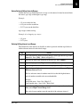
Sample Carousel
Component List
Component List
The following table lists each component of the sample carousel with its function.
Table 2.4
Number
Sample Carousel Components
Component
Function
1
Sample Carousel
Cover
Reduces evaporation of sample.
2
Sample Diluent
Bottles
Contain sample diluents.
3
Sample Racks
Hold sample tubes. (Refer to Racks in this
section of the manual.)
4
Dilution Segments
The various sample dilutions are automatically
made in the wells of the dilution segments
before delivery to the reaction wheel. The
disposable dilution segments are placed on the
system by the user.
5
Sample Bar Code
Reader
Scans bar codes on the sample carousel
including:
•
•
•
•
•
•
bar coded sample tubes
sample rack bar codes
background bar codes
calibrator bar codes
reagent bar code cards
calibrator bar code cards
6
Sample Carousel
Advance Button
7
Background Bar Code Informs instrument of presence or absence of
Label
sample tube. When the sample bar code reader
can read the background bar code, no sample
tube is present at that position.
IMMAGE 800 Operations Manual A11403
March 2004
Rotates the Sample Carousel to allow access for
loading sample racks, dilution segments, and
sample diluent bottles.
System Description
Page 2-11
2
Sample Crane
Description
Sample Crane
Description
The sample crane transfers samples and diluents. Sample dilutions are made in the
dilution wells and then delivered to the reaction wheel. The Sample Crane functions
in the same manner as the Reagent Crane. (Refer to Figure 2.7.)
1.
2.
3.
4.
Sample Probe/Mixer
Sample Syringe Pump
Sample Crane Wash Station
Sample Addition Ports
Figure 2.7
System Description
Page 2-12
Sample Crane
IMMAGE 800 Operations Manual A11403
March 2004
Sample Crane
Component List
Component List
The following table lists each component of the sample crane with its function.
Table 2.5
Number
1
Sample Crane Components
Component
Sample Probe
Function
Aspirates sample and diluent and dispenses
them into the dilution well. Aspirates diluted
sample from the dilution well and dispenses it
into a cuvette on the reaction wheel.
Sample Paddle Mixer Mixes the contents of a cuvette while diluted
sample is dispensed. Also mixes in dilution
wells.
2
Sample Syringe Pump Mechanism for accurate sample, diluent, and
(250 µL)
diluted sample aspiration and delivery through
the sample probe.
3
Sample Crane Wash
Station
Washes interior and exterior of sample probe/
mixer.
4
Sample Addition
Ports
Two openings in reaction module cover to allow
samples to be added to one of two different
cuvette locations.
IMMAGE 800 Operations Manual A11403
March 2004
System Description
Page 2-13
2
Upper Instrument Subsystems
Upper Subsystem List
Upper Instrument Subsystems
Upper Subsystem List
The upper portion of the instrument contains three subsystems.
• Hydro Pneumatics
• Electronics Control Compartment
• Power Supply Assembly
Hydro Pneumatics
The hydro pneumatics control the flow of wash solution through the system and the
flow of waste out of the system. Pressure and vacuum control this fluid motion.
(Refer to Figure 2.8.)
1. Pressure Reservoir-Liquid
2. Pressure Reservoir-Air
3. Vacuum Reservoir
Figure 2.8
System Description
Page 2-14
Hydro Pneumatics
IMMAGE 800 Operations Manual A11403
March 2004
Upper Instrument Subsystems
Electronics Compartment
Electronics Compartment
The electronics compartment contains the electronic circuit boards. (Refer to Figure
2.9.) Electronic circuit boards should only be handled by a Beckman Coulter service
representative.
1. Circuit Boards
Figure 2.9
Electronics Compartment
IMMAGE 800 Operations Manual A11403
March 2004
System Description
Page 2-15
2
Upper Instrument Subsystems
Power Supply Assembly
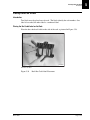
Power Supply Assembly
All of the power supplies used by the IMMAGE 800 instrument are contained in this
area of the instrument. (Refer to Figure 2.10.) Power supply assemblies should only
be handled by a Beckman Coulter service representative.
1. Power Tower
2. Power Switch
3. Electrical Outlet/Voltage Selector
Figure 2.10
System Description
Page 2-16
Power Supply Assembly
IMMAGE 800 Operations Manual A11403
March 2004
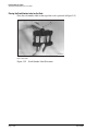
Wash Solution Box and Waste Container
Description
Wash Solution Box and Waste Container
Description
The wash solution box and waste container are stored separately from the IMMAGE
800 instrument. (Refer to Figure 2.11.)
1.
2.
3.
4.
Wash Solution Box
Wash Solution Tubing
Waste Container
Waste Tubing
Figure 2.11
Wash Solution Box and Waste Container
Component List
The following lists the components depicted in Figure 2.11.
Table 2.6
Item
Wash Solution Box and Waste Container Components
Component
Function
1
Wash Solution Box
Holds wash solution.
2
Wash Solution Tubing
(blue and orange)
Blue: Connects wash solution box to
instrument.
Orange: vents wash solution to box.
3
Waste Container
Holds waste. (A drain can be used instead.)
4
Waste Tubing (green)
Outlet for waste leading to waste container or
drain.
IMMAGE 800 Operations Manual A11403
March 2004
System Description
Page 2-17
2
Wash Solution Box and Waste Container
Wash Solution
Wash Solution
The wash solution is used to wash the probes, mixers, and cuvettes.
Wash Solution Box Placement
The wash solution box must be close enough to the instrument to allow connection of
the wash solution tubing.
Waste Container Placement
The waste container must be placed with the opening of the waste container no higher
than the top of the instrument.
System Description
Page 2-18
IMMAGE 800 Operations Manual A11403
March 2004
Racks
Description
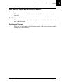
Racks
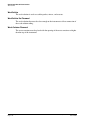
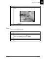
Description
Each sample rack holds up to nine sample tubes. Each rack is bar coded to allow
identification of the rack number by the instrument. (Refer to Figure 2.12.)
2
3
1
A012184P.EPS
1. Rack Bar Code Label
2. Rack Number
3. Handle
Figure 2.12
Sample Rack
Types of Racks
There are four types of racks. They are identified by the size of sample tube that they
hold. (Refer to APPENDIX A, Part Number List.)
•
•
•
•
16 × 100 mm
16 × 75 mm
13 × 100 mm
13 × 75 mm
Applying Rack Labels
Refer to CHAPTER 5, System Setup, Instrument Setup, Placing Labels on a Rack for a
detailed procedure for label placement.
IMMAGE 800 Operations Manual A11403
March 2004
System Description
Page 2-19
2
Racks
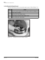
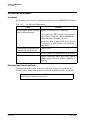
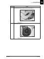
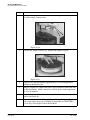
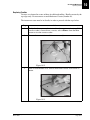
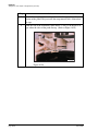
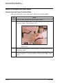
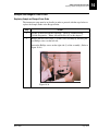
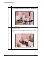
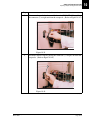
Loading Rack onto the Sample Carousel
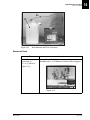
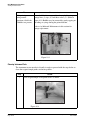
Loading Rack onto the Sample Carousel
Follow the steps below to load a rack onto the sample carousel. (Refer to Figure 2.13.)
Step
Action
1
Press the Advance button to advance the sample carousel to an empty slot.
2
Lift the rack by its handle.
3
Open the cover of the sample carousel.
4
Align rack pegs over holes in the sample carousel.
5
Lower rack pegs into carousel holes.
Figure 2.13
System Description
Page 2-20
Loading Rack onto the Sample Carousel
IMMAGE 800 Operations Manual A11403
March 2004
Computer
Description
Computer
Description
The computer supplies the user interface to the IMMAGE 800 Immunochemistry
System and stores data.
The user performs all software interaction on the computer portion of the system. This
software interaction is stored on the computer and is sent to the instrument at the
appropriate time.
Additionally, patient results, control results, and setup parameters are stored on the
computer.
NOTICE
Only the computer supplied by Beckman Coulter is to be used with the IMMAGE 800
Immunochemistry System.
Changing the Date on the PC
The PC supplied with some IMMAGE 800 systems contains a battery that provides
power to the computer’s internal clock during power off. The status of the battery is
checked every time the Power On sequence is performed.
CAUTION
The date and time must be reset each time the Power On sequence is performed on a
computer with a dead CMOS (Complementary Metal Oxide Semiconductor) battery.
Contact Beckman Coulter Clinical Support or the nearest local Beckman Coulter Field
Service office for assistance in replacing the battery.
IMMAGE 800 Operations Manual A11403
March 2004
System Description
Page 2-21
2
Computer
Changing the Date on the PC
Table 2.7
Number
1
Computer Components
Component
Personal Computer
(PC)
Description
The PC contains the:
•
•
•
•
System Description
Page 2-22
CPU (Central Processing Unit)
hard disk drive
floppy diskette drive
CD-ROM Drive
2
Floppy Diskette Drive Where a 3.5 inch floppy diskette is placed and
read.
3
CD-ROM Drive
Where a CD-ROM is placed and read.
4
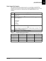
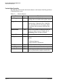
Keyboard
101- key enhanced keyboard.
5
Mouse
A two-button movable input device.
6
Monitor
Displays user interface (touch screen).
7
Uninterruptible Power The backup power source providing temporary
Source (UPS)
power to the computer for a limited period of
time in the event of brownouts or low line
voltage conditions.
IMMAGE 800 Operations Manual A11403
March 2004
Computer
Keyboard
Keyboard
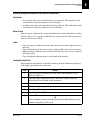
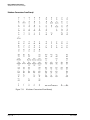
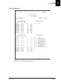
Figure 2.14 depicts the 101- key enhanced keyboard used on the IMMAGE 800.
1.
2.
3.
4.
5.
6.
7.
Escape Key
Function Keys
Tab Key
Caps Lock Key
Shift Keys
Control Keys
Alt Keys
Figure 2.14
8.
9.
10.
11.
12.
13.
Backspace Key
Enter Key
Delete Key
Page Up Key
Page Down Key
Arrow Keys
IMMAGE 800 Keyboard
IMMAGE 800 Operations Manual A11403
March 2004
System Description
Page 2-23
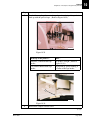
2
Computer
Port Connections
Port Connections
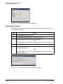
Figure 2.15 shows the back of the computer and where each cable connects.
1
3
2
4
A011412P.EPS
1.
2.
3.
4.
Printer Port
Monitor Port
Mouse/Keyboard Port
Instrument Port
Figure 2.15
CPU Ports
Proper Care and Handling of a Floppy Diskette
Diskettes require special care in handling.
• Recommended diskette: 3.5 inch Double-sided, High-density, IBM formatted
diskette.
• Store away from electrical motors, power supplies, or generators.
• Keep away from magnets and magnetic fields.
Proper Care and Handling of a Compact Disk
Compact disks (CD-ROMs) require special care in handling.
• Store away from direct sunlight, excessive heat, and humidity.
• Hold the CD-ROM by the edges.
• Replace the CD-ROM in its case after use.
System Description
Page 2-24
IMMAGE 800 Operations Manual A11403
March 2004
Printer
Description
Printer
Description
The printer supplied with the IMMAGE 800 Immunochemistry System is the HP
DeskJet printer. The printer is designed to use single sheet paper.
The printer is set up to use 8.5 × 11 inch paper. Paper size can be chosen in Printer
Setup.
Refer to the manual that accompanies the printer for proper setup, care, and handling
of the printer.
IMMAGE 800 Operations Manual A11403
March 2004
System Description
Page 2-25
2
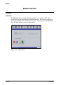
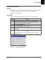
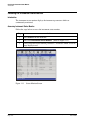
Overview
Introduction
Software Overview
Overview
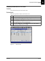
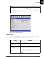
Introduction
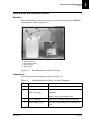
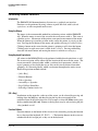
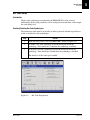
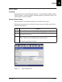
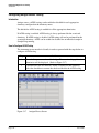
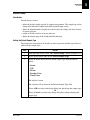
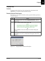
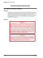
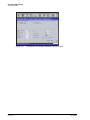
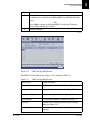
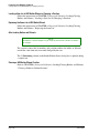
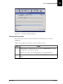
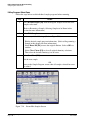
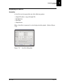
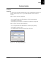
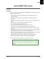
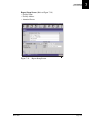
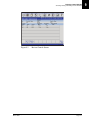
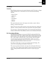
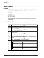
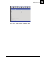
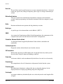
The IMMAGE 800 is controlled through a graphical user interface (GUI). This
section describes the basic functions within the interface. The concepts presented in
this section should be understood by the user before attempting to use the IMMAGE
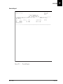
800. The Main Software screen is shown below.
E011433S.EPS
Figure 2.16
System Description
Page 2-26
Main Screen
IMMAGE 800 Operations Manual A11403
March 2004
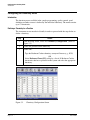
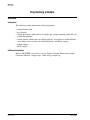
Screen Format
Introduction
Screen Format
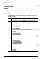
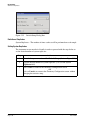
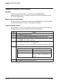
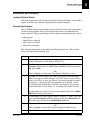
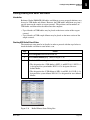
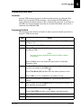
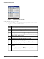
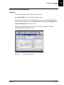
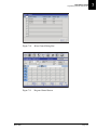
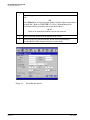
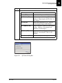
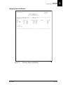
Introduction
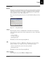
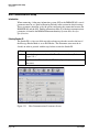
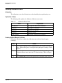
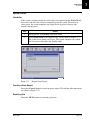
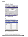
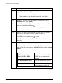
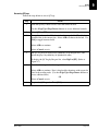
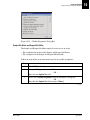
The IMMAGE 800 Immunochemistry System is designed to have a user friendly
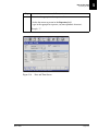
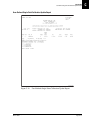
interface. Figure 2.17 shows the sample programming screen of the IMMAGE 800 as
an example of this interface. This screen is broken into six functional areas:
•
•
•
•
•
•
Status Bar
Menu Bar
Title Bar
Function Buttons
Message Bar
Working Area
3
1
2
4
7
5
6
E011413S.EPS
1.
2.
3.
4.
5. Function Buttons
6. Message Bar
7. Working Area
Status Bar
Menu Bar
Icon Button
Title Bar
Figure 2.17
Sample Programming Screen
Status Bar
The blue bar at the top of the screen is the status bar. This bar shows the instrument
status, date and time.
IMMAGE 800 Operations Manual A11403
March 2004
System Description
Page 2-27
2
Screen Format
Menu Bar
Menu Bar
Below the status bar is a row of icon buttons called the menu bar. These icon buttons
can be selected to access various functional areas of the interface. These areas are:
•
•
•
•
•
•
•
•
•
•
Main
Samples
Results
Rgts/Cal (Reagent load and calibration)
QC (Quality control)
Setup
Utils (Utilities)
Status
Stop - F12
About
The menu bar consists of these specific icon buttons regardless of the current screen.
Title Bar
Below the menu bar is a bar containing the title of the current screen with some
possible additional information.
Function Buttons
At the bottom of the screen is an area for up to ten function buttons. These function
buttons perform functions that are specific to the particular screen. Each function
button on the screen corresponds to a function key on the keyboard read from left to
right (F1, F2, F3, etc.). The screen function buttons are labeled with the action the
function button performs and the corresponding keyboard function key.
Options Button
Within the working area, and occasionally on screens or dialog boxes, are buttons that
perform a different function than the "F" numbered function buttons. These buttons,
called options buttons, appear triangular in shape (▼) and often accompany a text
field. When an options button is selected, it presents a list of items, or options, from
which a user may choose.
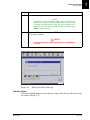
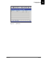
Message Bar
The blue bar at the bottom of the screen is the message bar. This bar is used for
instructions and error messages. The first line displays instructions and the second
line displays error messages. These messages are related to activities in the working
area. (Refer to Figure 2.18.)
System Description
Page 2-28
IMMAGE 800 Operations Manual A11403
March 2004
Screen Format
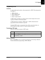
Working Area
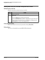
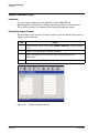
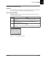
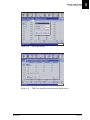
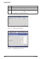
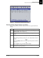
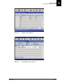
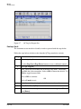
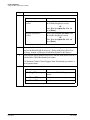
Working Area
The middle portion of the screen is referred to as the working area. The user enters
data into the working area via:
•
•
•
•
Text fields
Buttons
Toggle buttons
Check boxes
5
1
2
3
4
E010270S.EPS
1. Text Field
2. Cursor
3. Options Button
Figure 2.18
4. Toggle Button
5. Check Box
Working Area of Program Sample Screen
IMMAGE 800 Operations Manual A11403
March 2004
System Description
Page 2-29
2
Text Fields
Definition of Text Field
Text Fields
Definition of Text Field
Text fields are white areas on the screen in which the user types data.
Definition of Cursor
When a text field is chosen, a cursor displays in that field. This cursor indicates where
text will be entered.
Characteristics of Text Fields
Unless otherwise noted, most text fields can accept any alphanumeric characters. This
means that the user can type in any letter, number, or a space.
Each text field has a limited number of characters that can be entered. Most text fields
have a restricted set of characters that can be entered.
Example: If the user attempts to enter anything other than a number in a numeric field
the character will not be entered. A message will display which reads "Only numeric
characters are allowed."
NOTICE
The alphanumeric characters "|" (piping bar), "\" (backslash), " ^" (caret), and "&"
(ampersand) are not allowed because they are host interface delimiters.
System Description
Page 2-30
IMMAGE 800 Operations Manual A11403
March 2004
Buttons
Function
Buttons
Function
Buttons on the screen perform as their name implies. When they are selected or
"pressed" an action is performed in the software. Often this action will be used to
access a new screen or dialog box.
The icons in the menu bar and the function buttons on the bottom of the screen operate
like buttons.
Example
The options button <▼> next to the Sample Comment field on the Program Sample
screen is an example of a button.
IMMAGE 800 Operations Manual A11403
March 2004
System Description
Page 2-31
2
Toggle Buttons
Function
Toggle Buttons
Function
Toggle buttons function in the same manner as buttons, except when they are selected
or "pressed", their state is changed.
Selected or Unselected
Toggle buttons may either be in the selected or unselected state. If a toggle button is
selected it will be highlighted in blue.
Example
Each chemistry button in the list of chemistries on the Program Sample screen is an
example of a toggle button.
System Description
Page 2-32
IMMAGE 800 Operations Manual A11403
March 2004
Check Boxes
Function
Check Boxes
Function
Check boxes are similar to toggle buttons because they are either toggled on or off.
When selected, a check box will change state.
States
A check box is either checked or unchecked. When checked, a check mark will appear
in the check box.
Example
The STAT check box on the Sample Program screen is an example of a check box.
IMMAGE 800 Operations Manual A11403
March 2004
System Description
Page 2-33
2
Performing Software Functions
Introduction
Performing Software Functions
Introduction
The IMMAGE 800 Immunochemistry System uses a graphical user interface.
Functions can be performed by using a mouse to point and click, with keyboard
equivalents, or with an optional touch screen.
Using the Mouse
The mouse is the recommended method for performing actions with the IMMAGE
800. When the mouse is moved, the arrow on the screen moves with it. This arrow is
called the pointer. Movements of the pointer correspond to movements of the mouse.
When the pointer tip is touching an item on the screen, the pointer is pointing to that
item. Pressing the left button on the mouse and quickly releasing it is called clicking.
Clicking a button on the screen that the pointer is pointing to will select that button.
Clicking twice in rapid succession is called double-clicking. Pressing and holding
down the left mouse button and moving the mouse is referred to as dragging.
Using Keyboard Equivalents
All actions on the IMMAGE 800 can be performed with keyboard equivalents as well.
The screen navigation will be affected by the location of the cursor on the screen. The
cursor movement is directed either within a partition (local movement), which is a
logical grouping of data fields that may or may not be visually distinct from other
groupings, or is directed globally, which is movement throughout the entire screen.
Keyboard equivalent methods include:
•
•
•
•
•
•
[Alt + Key]
Function Buttons
Tabs + Spacebar
Arrow Keys + Spacebar
Page Up/Page Down Keys
Selecting a number from a list
[Alt + Key]
Icon buttons on the menu bar, at the top of the screen, can be selected by pressing and
holding down the [Alt] key and then pressing the key that corresponds to the
underlined letter in the title of that icon. For example, to show the Main screen, press
the key combination [Alt + m]. Buttons in dialog boxes may be selected using the [Alt
+ key] method as well.
Function Buttons
Functions buttons on the bottom of the screen can be selected by pressing the function
keys at the top of the keyboard (F1, F2, F3, ...). The function buttons on the screen are
numbered from left to right just as they are on the keyboard.
System Description
Page 2-34
IMMAGE 800 Operations Manual A11403
March 2004
Performing Software Functions
Tab + Spacebar
Tab + Spacebar
The items in the working area of the screen can be chosen by using the [Tab] key.
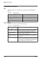
Pressing the [Tab] key moves the highlight forward (generally left to right and top to
bottom) through the various text fields and screen buttons that may be chosen. If the
item is a text field, data may be entered as soon as the item is chosen. If the item is a
button, the button can be selected by pressing the [Spacebar].
Arrow Keys + Spacebar
The Arrow Keys on the keyboard may also be used to move the highlight between the
various items on the screen that may be chosen. The highlight moves in the direction
of the arrow. If a text field is chosen, [ ← ] and [ → ] will move through each letter in
the field before moving to the next item. If the item is a text field, data may be entered
as soon as the item is chosen. If the item is a button, the button can be selected by
pressing the [Spacebar].
Page Up/Page Down Buttons
An exception to the use of the [Tab] key or arrow keys are page up/page down buttons.
These buttons cannot be chosen. The [Page Up] and/or [Page Down] keys on the
keyboard are equivalent to the <Page Up> and <Page Down> buttons, respectively.
Selecting a Number from a List
If there is a list of items to choose from, the user may select an item by typing the
number of the item in the text box and pressing [Enter].
A range of numbers can be entered by entering the first number followed by a dash
followed by the last number in the range (Example: 1-5 selects 1, 2, 3, 4, and 5).
A list of discontinuous numbers can be entered by separating the items with a comma
(Example: 1, 5, 8-10 selects 1, 5, 8, 9, and 10).
Using the Touch Screen
When the touch screen is used, the screen can be touched with a finger or any other
object. Any button on the screen can be selected by touching the button on the screen.
Any text field can be chosen by touching the field on the screen.
IMMAGE 800 Operations Manual A11403
March 2004
System Description
Page 2-35
2
Selecting vs. Choosing
Introduction
Selecting vs. Choosing
Introduction
Selecting an item or field is different from choosing the item or field. Text fields can
only be chosen. Buttons, toggle buttons, and check boxes can be chosen and selected.
"Choosing" Definition
Using the [Tab] key or arrow keys moves the user to the various items on the screen by
highlighting one item at a time. An item is highlighted when a dark line appears
around it. When the item is highlighted that item is chosen but no action occurs.
"Selecting" Definition
Pressing the [Spacebar] selects the chosen item on the screen. When an item is
selected the software performs the appropriate action.
Text fields cannot be selected, only chosen.
Selecting/Choosing by Mouse or Touch screen
Buttons, toggle buttons, and check boxes are selected with the user’s first action and
the [Spacebar] is not needed when using the mouse or touch screen.
System Description
Page 2-36
IMMAGE 800 Operations Manual A11403
March 2004
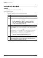
Dialog Boxes
Definition
Dialog Boxes
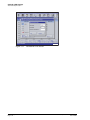
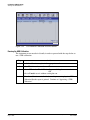
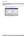
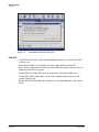
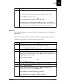
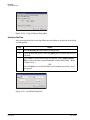
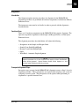
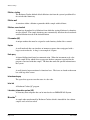
Definition
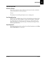
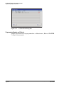
Dialog boxes are smaller than the total size of the screen and generally do not include
a bottom row of function keys. The purpose of a dialog box is to input a single piece
of data. This piece of data may be as simple as confirming the user’s request for the
system to perform an action. (Refer to Figure 2.19.)
Data is entered into dialog boxes the same as it is entered into the working area of any
screen.
E010254S.EPS
Figure 2.19
Dialog Box Example
<Cancel>
Most dialog boxes will have a <Cancel> button. This button closes the dialog box
without entering the requested data or denies confirmation of an action. If this button
is selected:
• no data is entered
• no action is performed
• the dialog box closes
This button can also be selected by pressing [Alt + c].
<OK>
Some dialog boxes will have an <OK> button. This button accepts the data being
entered or confirms a user’s request for an action. If this button is selected:
• the data is entered into the system or the action is performed
• the dialog box closes
This button can also be selected by pressing [Alt + o].
<Print> or <Display>
Some dialog boxes may contain <Print> or <Display> buttons.
IMMAGE 800 Operations Manual A11403
March 2004
System Description
Page 2-37
2
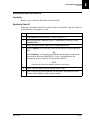
Deleting Data From a Text Field and Printing Data from a Screen
Deleting Data from a Text Field
Deleting Data From a Text Field and Printing Data from a Screen
Deleting Data from a Text Field
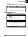
Follow the steps below to delete data from a text field.
Step
Action
1
Choose the text field.
2
Choose one:
• Press the [Delete] key to delete the entire field.
• Press the [Backspace] key to delete a single character prior to the cursor.
• Drag through any portion of the text to highlight it and then press the
[Backspace] key to delete the highlighted text.
Printing Data from a Screen
Many screens contain data that may be printed by selecting Print [F10].
Printing a Screen
Any screen can be printed by pressing [Ctrl] + [P] simultaneously.
System Description
Page 2-38
IMMAGE 800 Operations Manual A11403
March 2004
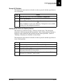
Page Up/Page Down
Definition of Multipage
Page Up/Page Down
Definition of Multipage
Some screens contain lists of data. If this list contains more data than an individual
screen can show the list is said to be multipage.
Example:
The chemistry list on the Program Sample screen is a multipage list.
Use of Page Up/Page Down
The user can access additional pages of data by selecting the page up and page down
buttons on the right. The page numbers are shown above the buttons. Selecting the
Page Down button will advance the page to the next page. Selecting the Page Up
button will return the page to the previous page. These buttons only appear if more
than one page of data exists.
Keyboard Equivalents
The keyboard equivalent of the screen Page Up and Page Down buttons are the [Page
Up] and [Page Down] keys, respectively.
IMMAGE 800 Operations Manual A11403
March 2004
System Description
Page 2-39
2
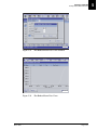
Program Structure
Introduction
Program Structure
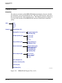
Introduction
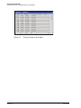
The software or interface of the IMMAGE 800 Immunochemistry System is divided
into functional areas based on different tasks. The icons in the menu bar at the top of
the screen represent the various functional areas. The following menu tree displays an
overview to the structure of the IMMAGE 800 software divided into its functional
groups.
Main
Stop
Home
Pause
Run
Samples
Control Batch [F1]
Demog [F2] (Demographics)
Program Sample [F1]
Save Next [F10]
Sample Options [F3]
Link Sample
Set Variable
OK
Cancel
Program Batch [F4]
Select Racks [F1]
End Batch [F10]
Select Control [F5]
Sample Options [F3]
Select Control [F5]
Clear Chem [F7]
Cancel/Edit [F9]
Save/Next [F10]
Rerun Samples [F6]
Edit Samples
Rerun Samples
Rerun Chems
Cancel
Clear Samples [F7]
Post Run Summary [F8]
Load List [F9]
Save/Next [F10]
E011369L.EPS
Figure 2.20
System Description
Page 2-40
IMMAGE 800 Program Tree (1 of 5)
IMMAGE 800 Operations Manual A11403
March 2004
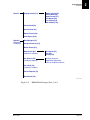
Program Structure
Introduction
Results
Display Results [F1]
Update Sample [F2]
Send to Host [F6]
Report Format [F7]
Print Report [F8]
Prev Sample [F9]
Next Sample [F10]
Cancel Send [F4]
Send to Host [F8]
Report Format [F9]
Print Report [F10]
Rgts/Cal
(Reagents/
Calibration)
Read Reagent [F1]
Reagent Summary [F2]
Buffer Diluent [F3]
Request Cal [F4]
(Request Calibration)
Clear Racks [F1]
Save [F9]
Cancel [F10]
Cal Options [F5]
(Calibration Options)
Calibrator Summary
Slope/Offset Adjustment
Print Last Calibration Results
Cal LdList [F6]
(Calibration Loadlist)
Cancel Request [F7]
Read Cards [F8]
E011370L.EPS
Figure 2.21
IMMAGE 800 Program Tree (2 of 5)
IMMAGE 800 Operations Manual A11403
March 2004
System Description
Page 2-41
2
Program Structure
Introduction
QC
(Quality
Control)
Review Control [F1]
Control ID [F2]
Delete Control [F3]
Print Control [F10]
Define/Edit [F2]
Add/Del Chems [F1]
Control ID [F2]
Delete Control [F3]
Delete Control [F3]
QC File List [F4]
List CtlName [F1]
List File# [F2]
List SelChem [F3]
List AllChem [F4]
Print [F10]
QC Log [F5]
QC Log [F1]
Reagent Lot [F2]
Delete Result [F3]
*Action Log [F4]
Print [F10]
QC Summary [F6]
Print Inter-Lab [F9]
Print [F10]
QC Chart [F7]
Control Chems [F1]
QC File # [F2]
Print [F10]
Figure 2.22
System Description
Page 2-42
IMMAGE 800 Program Tree (3 of 5)
IMMAGE 800 Operations Manual A11403
March 2004
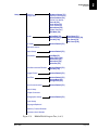
Program Structure
Introduction
Setup
Chemistry
Configuration
Beckman Chems [F1]
(Beckman Chemistries)
Define PrtName [F3]
(Define Print Name)
Clear All [F4]
Insert Chem [F5]
(Insert Chemistry)
Delete Chem [F6]
(Delete Chemistry)
UDR Main [F9]
Panels
Define/Edit [F1]
Delete Panels [F2]
Print All [F10]
Bar Code
Restore Default [F1]
Clear Chem [F1]
Panels Summary [F2]
Prev. Panel [F9]
Next Panel [F10]
Reference Interval
Report Setup
Restore Default [F1]
Calculations
View/Edit [F1]
Select TUrine [F2]
Define Calc [F3]
Delete Calc [F4]
Define Var [F5]
Units/Non-standard Dilutions
Restore Default [F1]
Print All [F10]
Antigen Excess
Restore Default [F1]
Date/Time
Restore Default [F1]
Change Date [F2]
Change Time [F3]
Host Communications
Restore Default [F1]
Default Setup
Sample Comments
Demographics Setup
Restore Default [F1]
Printer Setup
Languages/Keyboard
Chemistry Protocol Diskette
Instrument Serial Number
Figure 2.23
IMMAGE 800 Program Tree (4 of 5)
IMMAGE 800 Operations Manual A11403
March 2004
System Description
Page 2-43
2
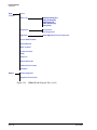
Program Structure
Introduction
Prime
Utils
(Utilities)
Event Log
Display Events [F1]
Copy to Disk [F2]
Date/Time [F3]
Clear Events [F4]
Print [F10]
Diagnostics
Cycle Count
Call. Diagnostics
Alignment
Prev Align [F1] (Previous Alignment)
Format QNX Diskettes
Backup/Restore
Wash Cuvettes
Fill Internal Wash
Bottle
Stop Print
Reload DAS Code
Calibrate Touch Screen
Shutdown
Dilution Segments
Status
Sample Carousel Status
Figure 2.24
System Description
Page 2-44
IMMAGE 800 Program Tree (5 of 5)
IMMAGE 800 Operations Manual A11403
March 2004
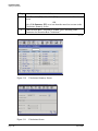
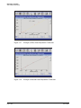
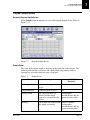
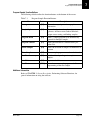
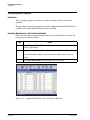
Sample Programming Overview
Introduction
Sample Programming Overview
Introduction
This section summarizes the sample programming methods for the IMMAGE 800
Immunochemistry System.
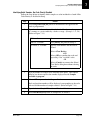
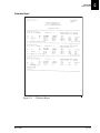
Sample Programming Options
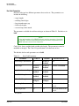
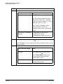
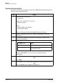
The following table will summarize the sample programming options based on the
variables of bar coded samples and host interface. For detailed explanations of sample
programming refer to CHAPTER 7, Sample Programming, of this manual.
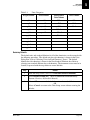
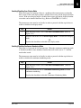
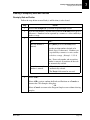
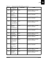
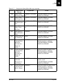
Table 2.8
Bar Coded
Samples
Sample Programming Options
Host Interface
Sample Programming
Yes
Host Query
None required. Load samples in any rack and
position.
No
Bi-directional
None required. Load samples in rack and
position assigned by host.
Yes
Bi-directional
None required. Load samples in any rack and
position.
No
Unidirectional
Required. Enter rack and position number,
sample ID, and chemistries. Load samples in
assigned rack and position.
Yes
Unidirectional
Required. Enter sample ID, and chemistries.
Load samples in any rack and position.
No
None
Required. Enter rack and position number,
sample ID, demographics, and chemistries.
Load samples in assigned rack and position.
Yes
None
Required. Enter sample ID, demographics, and
chemistries. Load samples in any rack and
position.
IMMAGE 800 Operations Manual A11403
March 2004
System Description
Page 2-45
2
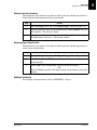
Instrument Specifications
Placement
System Specifications and Characteristics
Instrument Specifications
Placement
The surface on which the unit rests must be free of vibration and must be level, 1° or
<0.75 inch (1.9 cm) slope across the length and the width of the instrument. Do not
place instrument in direct sunlight or drafts or near a heating or cooling duct.
Clearance
Sides - 6 inches (15.2 cm) minimum
Back - None
Front - 3 inches (7.6 cm) minimum
Top - 4 inches (10.1 cm) from top of instrument
Dimensions (Excluding Wash and Waste Bottles)
Height = 30 inches (76.2 cm)
Depth = 25.5 inches (64.8 cm)
Length = 43.5 inches (110.5 cm)
Weight
250 lb. (120 kg)
Power Requirements
Operating Range
Frequency
Transient Suppression
BTU Generated
Electrical Outlet
Surge Protector
Current
115 (90-132) VAC RMS, Single Phase
230 (180-264) VAC RMS, Single Phase
50/60 Hz nominal (47-63 Hz)
Recommended
2,900 BTU/hour
Grounded per Local Code
Recommended
8.0 Amps (normal) 12 Amps surge
Temperature and Humidity
Ambient Temperature
Ambient Relative Humidity (RH)
Reagent Compartment Temperature
Reaction Module Temperature
System Description
Page 2-46
+15°C to +32°C
15% to 85% (non-condensing)
13-22°C (32°C Ambient, <45%RH)
+37°C ± 0.5°C
IMMAGE 800 Operations Manual A11403
March 2004
Instrument Specifications
Drain Requirements
Drain Requirements
Flow Rate: 3 Liters/hour minimum
Waste Container Placement: The opening should be no higher than the top of the
instrument.
Regulatory Agency Approvals
The IMMAGE 800 meets the safety requirements for the following agencies: CE, UL,
CSA, IEC and CENFLEC.
Environmental Conditions
System can operate up to 8000 ft. (2,438m) elevation.
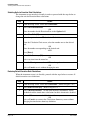
Capacities
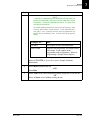
The following table lists various system capacities.
Table 2.9
System Capacities
Item
Capacity
Reagents
24 reagent cartridges can be loaded.
Reagent cartridge
40, 150, or 300 tests per cartridge.
Reaction buffers
4 bottles can be loaded.
Buffer bottle
120 mL: 350 tests.
Samples
72 samples can be loaded.
Sample diluents
4 bottles can be loaded.
Diluent bottles
120 mL: number of dilutions is workload dependent.
Sample dilution segments
4 segments of 36 wells each.
Dilution well
300 µL.
Wash solution
1 box/10 L/approximately 1,000 tests.
Waste container
5 gallons (18.9 L).
IMMAGE 800 Operations Manual A11403
March 2004
System Description
Page 2-47
2
Peripheral Devices Specifications
Introduction
Peripheral Devices Specifications
Introduction
Refer to the inserts which accompany the respective peripheral devices (computer,
printer, etc.) for product specifications.
System Description
Page 2-48
IMMAGE 800 Operations Manual A11403
March 2004
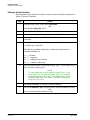
Sample Containers Allowed
Introduction
Sample Container Information
Sample Containers Allowed
Introduction
The following categories document specifications for sample containers that can run
on the IMMAGE 800 Immunochemistry System.
Primary Tubes
16 × 100 mm (10 mL)
16 × 75 mm (7 mL)
13 × 100 mm (7 mL)
13 × 75 mm
16.5 × 92 mm
Secondary (Aliquot) Tubes
16 × 100 mm
16 × 75 mm
13 × 100 mm
12 × 75 mm
Microtubes
13 × 100 mm SYNCHRON® Microtube™
Sample Cups
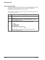
NOTICE
Low humidity and high ambient temperature may cause evaporation when using small
volumes of sample in sample cups. To minimize evaporation:
• Program samples in positions A or B on the sample carousel.
OR
• Program samples as STATS.
2 mL (placed into a sample cup holder)
0.5 mL (placed into a sample cup holder)
IMMAGE 800 Operations Manual A11403
March 2004
System Description
Page 2-49
2
Bar Code Types and Options
Introduction
Bar Code Types and Options
Introduction
Four bar code types are supported by the IMMAGE 800:
•
•
•
•
Code 39
Code 128
Interleaved 2 of 5
Codabar
The bar code scanner will read any of these bar code types, provided the type is
enabled in Bar Code Setup and the options match those defined for the bar code label.
The scanner will also automatically discriminate between the symbologies, so tubes
with bar code labels of different types may be intermixed in a run.
Code 39 Options
Check Digit: If a higher degree of data integrity is required, a check digit may be
enabled and added to the bar code ID. The check digit used is a Modulus 43, which is
the sum of all the character values and is the last digit of the bar code ID. Code 39
expects the check digit to be included in the final code length.
Large Intercharacter Gap: In Code 39, the intercharacter gap has a minimum value of
one times the width of the narrow element and a maximum value of three times the
width of the narrow element, or 0.06 inches (0.152 cm), whichever is greater. This
feature should be enabled when the intercharacter gap exceeds four times the narrow
element width.
Fixed Code Length: If the sample IDs being used are all of the same length, Fixed
Code Length may be enabled to ensure that only one length of sample ID is accepted.
Define Code Length: When Fixed Code Length is enabled, the code length may be
defined as from 1 to 15 characters.
Code 128 Options
The options for Code 128 bar codes are fixed in the software and cannot be
reconfigured by the user. The IMMAGE 800 uses Code 128 formatting to read
BECKMAN COULTER bar coded cards and rack ID.
Fixed Code Length: disabled.
System Description
Page 2-50
IMMAGE 800 Operations Manual A11403
March 2004
Bar Code Types and Options
Interleaved 2 of 5 Options
Interleaved 2 of 5 Options
Check Digit: If a higher degree of data integrity is required, a check digit may be
enabled and added to the bar code ID. The check digit used is a Modulus 10.
Interleaved 2 of 5 expects the check digit to be included in the final code length.
Code Length One: An even number from 0 to 14 must be defined as the number of
characters in the code.
Code Length Two: A second code length (an even number from 0 to 14) may be
defined. Both lengths would then be recognized.
Codabar Options
Start and Stop Codes Match: When this option is enabled, the start code and stop code
must be the same character for a valid read.
Large Intercharacter Gap: This option is used when reading Codabar labels with large
gaps between bar code characters. The normal intercharacter gap cannot exceed one
character element.
Fixed Code Length: If the sample IDs being used are all of the same length, Fixed
Code Length may be enabled to ensure that only one length of sample ID is accepted.
Define Code Length: When Fixed Code Length is enabled, the code length may be
defined as from 1 to 15 characters.
IMMAGE 800 Operations Manual A11403
March 2004
System Description
Page 2-51
2
Bar Code Label Specifications
Industry Standards
Bar Code Label Specifications
Industry Standards
American National Standards (ANSI X3.182.1990)
American Society for Testing Materials (ASTM E1466-92)
Symbol Size
Maximum overall length: 60 mm (2.36 inch)
(Includes bar code symbol with 5 mm (0.20 inch) quiet zone at each end.)
Minimum height: 10 mm (0.40 inch)
Symbol Content
Maximum of 15 characters.
Recommended symbol content printed on label in human-readable form. Square
bracket ([ or ]), percentage sign (%), dollar sign ($), comma (,) quotation mark ("),
ampersand (&), asterisk (*), semi-colon (;), question mark (?), back slash (\), caret (^),
tilde (~), or piping bar (|) cannot be used as a character.
Margin of Reading Accuracy
Bar code symbol (narrow) element width of 0.19 to 0.51 mm (0.0075 to 0.02 inch)
Wide-element to narrow-element ratio of 2.2:1 to 3.0:1.
Placing a Tube into a Rack
Tubes should be seated to the bottom of the rack with the bar code label facing the
same direction as the rack label.
Label Print Quality
Printed by direct thermal or thermal transfer.
Label Symbologies
Code 39
Interleaved 2 of 5
Codabar
Code 128
Check Characters
The use of check digits and fixed length codes is highly recommended where possible.
This greatly reduces the possibility of scanning errors.
System Description
Page 2-52
IMMAGE 800 Operations Manual A11403
March 2004
Bar Code Label Specifications
Label Sources
Label Sources
All patient and control sample labels are supplied by the customer. Preprinted labels
can be used, or labels generated by a bar code printer. Beckman Coulter, Inc.
recommends the following printers:
Execuport 2400
Computer Transceiver Systems
P.O. Box 1117
23 Carol Street
Clifton, NJ 07014-0996
Phone: (201) 473-4700
Intermec 3000A
Intermec Corporation
6001 36th Avenue West
Everett, WA 98203
Phone: 1-800-755-5505
Zebra 130
Zebra Technologies Corp.
333 Corporate Woods Parkway
Vernon Hills, IL 60061
Phone: (708) 634-6700
Please contact any of the above vendors or industry standard associations for any
specific bar code application issues.
IMMAGE 800 Operations Manual A11403
March 2004
System Description
Page 2-53
2
Applying Bar Code Labels
Correct Application of Bar Codes
Applying Bar Code Labels
Correct Application of Bar Codes
Refer to the IMMAGE Sampling Template for the correct application of bar codes.
System Description
Page 2-54
IMMAGE 800 Operations Manual A11403
March 2004
Sample Volume
Minimum Volumes
Sample Volume
Minimum Volumes
Refer to the IMMAGE Sampling Template for minimum volume requirements.
Primary Tube Sampling Template
Before running a primary tube on the IMMAGE 800, verify sample tube volume level
with the IMMAGE Sampling Template.
IMMAGE 800 Operations Manual A11403
March 2004
System Description
Page 2-55
2
Loading Tubes Into Racks
Guidelines
Loading Tubes Into Racks
Guidelines
• Remove stoppers from sample tubes before loading.
• Load the sample tubes onto the racks with the bar code labels facing the same
direction as the sample rack bar code label. (Refer to Figure 2.25.)
• Confirm that the tube is properly seated in the bottom of the rack.
• Be sure the entire bar code symbol, including quiet zone, is visible through the rack.
NOTICE
The bar code must be visible to the Sample Bar Code Reader, otherwise the sample will
not be identified or run.
Example
1. Rack Bar Code Label
Figure 2.25
System Description
Page 2-56
Bar Coded Tube Orientation
IMMAGE 800 Operations Manual A11403
March 2004
Instrument Operation
Introduction
Instrument Operation Overview
Instrument Operation
Introduction
The following tables describe instrument functions during start-up, sample processing,
and data reduction.
Start-up
The following tables explain what happens after all reagents and samples have been
loaded and Start Run has been selected.
Table 2.10
Start Up Functions
Stage
1
Description
The IMMAGE 800 will:
•
•
•
•
home moving parts
prime wash through the lines
wash the probes
perform internal diagnostic checks
2
A fluid level sense is performed on all Buffer and Diluent bottles. The %
volume remaining is then calculated.
3
Sample and Reagent carousels are spun. Bar codes for both reagent and
samples are read.
If the reagent load procedure has been performed and the reagent cover has
not been opened, the reagent carousel is not reread.
4
The on-board reference cuvette is read as part of optical quality control.
Sample Processing
The following table describes typical sample processing performed by the IMMAGE
800.
Table 2.11
Sample Processing Functions
Stage
Description
1
Buffer is added to the reaction cuvette, followed by a 5 minute incubation
to allow temperature equilibrium.
2
Sample or diluted sample is added to the reaction cuvette with mixing.
3
Reagent is then dispensed with mixing.
4
The reaction is monitored from 90 seconds up to 5 minutes depending on
the chemistry.
(1 of 2)
IMMAGE 800 Operations Manual A11403
March 2004
System Description
Page 2-57
2
Instrument Operation
Data Reduction
Table 2.11
Sample Processing Functions, continued
Stage
Description
5
Chemistries which utilize AGXS testing have antigen dispensed and their
reaction monitored for an additional 20 seconds.
6
The instrument will automatically make the appropriate dilution for high
or low samples to obtain the final answer. Samples which exceed the
instrument range will be flagged as Out-of-Range Hi or Out-of-Range Lo.
Note: During the run, the system tracks all reagent volumes and can
switch to another bottle of the same lot number. If there are no additional
reagents of that lot number, the test will be set to Pending prior to
aspiration of sample or reagent.
(2 of 2)
Data Reduction
The following table describes the typical data reduction process performed by the
IMMAGE 800.
Table 2.12
Data Reduction Functions
Stage
Description
1
The reaction wheel operates on a 5 second cycle time. During each cycle,
the cuvettes are spun in front of the optics station and 200 data points are
taken. These 200 points per cuvette are then calculated to a single value.
2
For each spin, the calculated value, the time the data was taken, and a
calculated quality value is logged for each cuvette.
3
When the reaction incubation time has expired on each cuvette, the data
logged for that cuvette is checked for certain mathematical bounds.
4
The data is then checked for an increasing signal, indicative of a reaction.
5
Passing the checks, the data is then mathematically curve fitted to a nonlinear function. The rate of scatter intensity is calculated from the resulting
curve.
6
The rate is directly related to the concentration.
7
A concentration test result is calculated based on the calibration factor, the
rate, and any dilution factors used.
8
Results may be scaled into alternative reporting units defined by the user.
System Description
Page 2-58
IMMAGE 800 Operations Manual A11403
March 2004
3
CHAPTER 3 Theory of Operations
Table of Contents
Theory of Operations .................................................................................................................. 3-2
Principles of Methodologies ................................................................................................... 3-2
Signal Measurement and Reaction Dynamics ........................................................................ 3-3
Antigen Excess Testing ........................................................................................................... 3-8
Out-of-range Testing ............................................................................................................. 3-11
Calibration ............................................................................................................................. 3-12
IMMAGE 800 Operations Manual A11403
March 2004
Theory of Operations
Page 3-1
Principles of Methodologies
Principles of Rate Nephelometry
Theory of Operations
Principles of Methodologies
Principles of Rate Nephelometry
The rate nephelometer measures the increase in the intensity of light scattered by
particles suspended in a cuvette. The light source for the rate nephelometer is a 670
nm laser. The detector is placed at a 90° angle from the laser beam to measure light
scatter, as shown in Figure 3.1.
Principles of Rate Turbidimetry
The rate turbidimeter measures the decrease in the intensity of light as it passes
through a solution of light scattering particles in a cuvette. The light source for the
rate turbidimeter is an light emitting diode (LED) at a wavelength of 940 nm.
Turbidimetric measurements are made at 0° from the incident beam as shown in
Figure 3.1.
1.
2.
3.
4.
5.
LED light source (turbidimetric)
Laser light source (nephelometric)
Focus lens
Beam splitter
Reaction cuvette
Figure 3.1
Theory of Operations
Page 3-2
6.
Nephelometric detector
(90° angle to incident laser beam)
7. Laser light bounces into light trap
8. Turbidimetric detector (0° angle to the
incident LED beam)
IMMAGE 800 Rate Nephelometer and Rate Turbidimeter Basic
Components
IMMAGE 800 Operations Manual A11403
March 2004
Signal Measurement and Reaction Dynamics
Light Scatter Signal Development
Signal Measurement and Reaction Dynamics
Light Scatter Signal Development
During an antigen-antibody reaction, immunoprecipitin complexes are formed.
In rate nephelometry, the light scattered at 90° increases as the complexes are formed.
In rate turbidimetry, the light intensity at 0° decreases as the complexes are formed.
This decrease is converted to an increasing scatter signal by the formula:
scatter signal = -Log 10
light intensity
initial light intensity
E011367L.EPS
Rate nephelometry and rate turbidimetry give the same signal as illustrated in
Figure 3.2.
2
Y
5
4
3
X
1. X = Increasing time
2. Y = Increasing scatter signal
3. Buffer Addition
Figure 3.2
1
A011368L.EPS
4. Sample Addition
5. Antibody Addition
Scatter Signal versus Time for Rate Nephelometry and Rate
Turbidimetry
Rate Determination
The system monitors scatter signal from the antigen antibody reaction at 5 second time
intervals. At the end of the reaction, the system mathematically calculates the rate of
change of the scatter signal.
IMMAGE 800 Operations Manual A11403
March 2004
Theory of Operations
Page 3-3
3
Signal Measurement and Reaction Dynamics
Dynamic Blanking
Dynamic Blanking
The IMMAGE 800 automatically performs a patented dynamic blanking algorithm for
selected analytes when testing at low serum dilutions. The results are improved by
elimination of the nonspecific light scatter produced by the polymer enhanced reaction
buffer interacting with the serum.
Dynamics of the Immunoprecipitin Reaction
The formation of light scattering complexes is dependent on the presence of antigen
and antibody molecules in optimal proportions. In general, the reagent contains a
fixed amount of antibody which binds with antigen in the sample to form light
scattering complexes. (Refer to Figure 3.3.)
1
4
5
6
4
5
7
4
5
8
2
3
A011357L.EPS
1.
2.
3.
4.
Antibody excess
Optimal proportion
Antigen excess
Antigen
Figure 3.3
Theory of Operations
Page 3-4
5.
6.
7.
8.
Antibody
Soluble complexes
Insoluble complexes
Soluble complexes
Antigen-antibody Reaction Under Varying Concentrations Of Antigen
And Antibody
IMMAGE 800 Operations Manual A11403
March 2004
Signal Measurement and Reaction Dynamics
Protein Rate Response Curve
Protein Rate Response Curve
Figure 3.4 illustrates the rate response for several test samples with various antigen
concentrations. The antibody is maintained at a constant level. The magnitude of the
rate response increases from test sample A to test sample F. The rate response for test
sample G is less than for sample F, although the antigen concentration in sample G is
greater than sample F. Test sample H illustrates a further reduction in the rate response
due to the increase in antigen concentration in the sample.
F
3
2
G
E
H
Y
D
C
B
A
X
1
A011358L.EPS
1. X = Increasing Antigen Concentration
2. Y = Peak rate of scatter
3. A-H represent peak response values at varying antigen concentrations.
The antibody is maintained at a constant level.
Figure 3.4
Protein Rate Response Curve
IMMAGE 800 Operations Manual A11403
March 2004
Theory of Operations
Page 3-5
3
Signal Measurement and Reaction Dynamics
Dynamics of Inhibition of Immunoprecipitin by Hapten (Drug)
Dynamics of Inhibition of Immunoprecipitin by Hapten (Drug)
In the drug assays, the conjugate is prepared by linking several hapten (drug) residues
to a high molecular weight carrier. The conjugate competes with the free drug
(hapten) in the sample for available binding sites on the antibody. Increased drug in
the sample results in a decrease in the formation of insoluble complexes. Figure 3.5
illustrates the conjugate antibody reaction in the presence of hapten (drug).
A.
1
+
1
2
3
4
B.
2
+
1
2
3
4
3
5
A011359L.EPS
1. Conjugate-antibody complexing
2. Inhibition of complexing by hapten
3. Conjugate Antibody
Figure 3.5
Theory of Operations
Page 3-6
4. Antibody
5. Hapten
Inhibition of Immunoprecipitin by Hapten (drug)
IMMAGE 800 Operations Manual A11403
March 2004
Signal Measurement and Reaction Dynamics
Drug Rate Response Curve
Drug Rate Response Curve
In drug assays the rate response decreases with increasing hapten (drug) concentration.
Figure 3.6 illustrates the rate response for several test samples with various hapten
concentrations. The magnitude of the rate response decreases from test sample A to
test sample E. Sample E has a very low rate response indicating a high hapten
concentration in the sample.
A
2
B
Y
3
C
D
E
X
1
A011360L.EPS
1. X = Increasing free hapten (drug) concentration
2. Y = Peak rate of scatter
3. A-E represent peak rate values at varying free hapten levels.
Specific antibody and drug conjugate remain at constant levels.
Figure 3.6
Drug Rate Response Curve
IMMAGE 800 Operations Manual A11403
March 2004
Theory of Operations
Page 3-7
3
Antigen Excess Testing
Overview
Antigen Excess Testing
Overview
Antigen excess (AGXS) testing is only necessary for some IMMAGE 800 protein
reagents.
Immunoglobulin G (serum IGG, urine IGU), Immunoglobulin A (IGA),
Immunoglobulin M (IGM), Kappa (KAP), Lambda (LAM), Haptoglobin (HPT), Urine
Transferrin (TRU), Alpha-1-Microglobulin (A1M), Microalbumin (MA) and Albumin
(ALB) which are identified by the system as ambiguous, are tested for antigen excess
condition if AGXS testing is enabled. (Refer to CHAPTER 5, System Setup,
Configuring Antigen Excess Testing.) A reaction is ambiguous if the rate response
could represent either an antigen excess or an antibody excess reaction.
Antibody Excess
When the reaction is to the left of the optimal antibody-antigen proportions (center
line), the reaction is in antibody excess (AbXS). (Refer to Figure 3.7.) This indicates
all the antigen in the sample is bound, forming complexes. This is the ideal condition
for the reaction to take place.
Antigen Excess
When the reaction is to the right of the optimal antigen-antibody proportions (center
line), the reaction is in antigen excess (AgXS) and the rate response will start to
decrease due to excessive levels of antigen. (Refer to Figure 3.7.)
Theory of Operations
Page 3-8
IMMAGE 800 Operations Manual A11403
March 2004
Antigen Excess Testing
Ambiguous Response
Ambiguous Response
It is possible for two significantly different sample concentrations of antigen to yield
the same rate response. Either the rate response represents the correct concentration in
the area of AbXS (left side) or the same rate response represents a concentration that is
in the area of AgXS (right side) and requires further dilution. Antigen excess testing
differentiates these two situations. (Refer to Figure 3.7.)
3
4
2
Y
X
1
A011361L.EPS
1. X = Increasing antigen concentration
2. Y = Rate response
Figure 3.7
3. Antibody excess (AbXS)
4. Antigen excess (AgXS)
Antigen Excess Detection
IMMAGE 800 Operations Manual A11403
March 2004
Theory of Operations
Page 3-9
3
Antigen Excess Testing
How Antigen Excess Testing is Performed
How Antigen Excess Testing is Performed
The system performs antigen excess testing by adding additional antigen to the
completed reaction.
Table 3.1
Antigen Excess Testing
If unbound Ab is... the addition of more Ag will and the IMMAGE 800 will...
result in...
present
an increase in rate response, as use the initial rate response to
indicated by the solid line in calculate the final result.
Figure 3.8
not present
no increase in rate response, automatically rerun the
as indicated by the broken line sample at the next higher
in Figure 3.8
dilution and test for antigen
excess until a final result is
obtained.
2
3
Y
4
X
1
A011362L.EPS
1. X = Reaction time (in seconds)
2. Y = Rate response
Figure 3.8
Theory of Operations
Page 3-10
3. Response if antibody excess
4. Response if antigen excess
Rate Response versus Reaction Time
IMMAGE 800 Operations Manual A11403
March 2004
Out-of-range Testing
Description of Out-of-range Testing
Out-of-range Testing
Description of Out-of-range Testing
The IMMAGE 800 reagents have been optimized so that the initial measuring range
will include the majority of the expected concentration values. Each reagent bar code
card contains information which defines the out-of-range high and out-of-range low
limits. Samples above or below the initial measuring range will automatically be
retested at the next appropriate dilution (refer to IMMAGE Immunochemistry Systems
Chemistry Information Manual Appendix B, Measuring Ranges/Dilution Fluids for
dilution scheme).
IMMAGE 800 Operations Manual A11403
March 2004
Theory of Operations
Page 3-11
3
Calibration
Calibration Curve
Calibration
Calibration Curve
The calibration curve for each lot of reagent is determined by Beckman Coulter, Inc.
In general, the calibration curve is formed from eight to twelve standards of known
analyte concentrations, with approximately thirty points per standard, tested on
multiple systems. The calibration curve parameters are coded onto a lot specific
reagent bar code card. When a reagent bar code card is read, the curve parameter
information is transferred and stored by the system.
System Calibration
System calibration is accomplished by testing a single analyte concentration which is
contained in a specific calibrator. To ensure a valid calibration, the system requires
that the rate response of two replicates obtained during calibration is reproduced
within a predefined percentage. The averaged rate of the two replicates is used to
establish a calibration scale factor based on the assigned calibrator target value. The
calibration scale factor is used to adjust the measured rate response to equal the
theoretical response.
Protein Calibration Curve
When the antibody concentration is constant, the rate response will increase as antigen
concentration increases. The maximum rate response occurs when the antibody and
antigen are in optimal proportions. As antigen concentration increases further, the rate
response will then progressively decrease. The regions at lower and higher antigen
concentration are called antibody excess and antigen excess, respectively.
Drug Calibration Curve
When the concentration of conjugate and specific antibody are constant, the rate
response will decrease as drug (hapten) concentration increases. The maximum rate
response occurs when the drug is absent, and the maximum amount of antibody is
available to react with the conjugate.
Theory of Operations
Page 3-12
IMMAGE 800 Operations Manual A11403
March 2004
4
CHAPTER 4 System Power On/Off
Table of Contents
System Power On/Off ................................................................................................................. 4-2
System Power On .................................................................................................................... 4-2
System Power Off ................................................................................................................... 4-4
Database Recovery .................................................................................................................. 4-5
Software Installation Instructions ........................................................................................... 4-6
IMMAGE 800 Operations Manual A11403
March 2004
System Power On/Off
Page 4-1
System Power On
Introduction
System Power On/Off
System Power On
Introduction
After the IMMAGE® 800 Immunochemistry System installation, the system can be
powered on.
Power On Sequence
Follow the steps below to power on the IMMAGE 800 system.
Step
Action
1
Check that the floppy disk drive is empty.
2
Turn on the printer.
3
Turn on the monitor.
4
Turn on the CPU.
5
Verify that the UPS is on. (The UPS power switch is on and the power
indicator light is on.)
6
Turn on the instrument.
7
Close reagent and sample carousel covers.
8
When the note is displayed to check dilution segment status, select <OK>.
9
When the temperature warning note displays, select <OK>.
• The system will continue to bring the reagent chamber and reaction
cuvettes to the appropriate temperature range.
• The system will not allow a run to start until the reaction cuvettes are
within the appropriate temperature range.
10
Refer to CHAPTER 11, System Status/Instrument Commands, Checking
Dilution Segment Status and Clearing Dilution Segments, and CHAPTER
7, Sample Programming, Checking Status and Clearing/Replacing
Dilution Segments.
11
Refer to the appropriate chapters in this manual to operate the system.
System Power On/Off
Page 4-2
IMMAGE 800 Operations Manual A11403
March 2004
System Power On
Additional Information
Additional Information
• Refer to CHAPTER 1, General Information/Precautions and Hazards for a
description of switches and port connections.
• Refer to CHAPTER 2, System Description, Computer, Printer, for the location of
appropriate switches and connections.
• Refer to the instruction manual provided with the UPS for specific information on
the UPS.
IMMAGE 800 Operations Manual A11403
March 2004
System Power On/Off
Page 4-3
4
System Power Off
Introduction
System Power Off
Introduction
It is recommended that the instrument remains powered on and in Standby when not in
use.
Powering off the system is recommended for the following situations:
• when parts replacement procedures specify power to be turned off
• when moving the system to a new location
• when lab power goes off (the console is protected by the UPS)
Once the procedure is complete or lab power is restored, power on the system.
Power Off Sequence
The instrument status must be in Standby in order to proceed with the steps below to
power off the IMMAGE 800 system.
NOTICE
The database may become corrupted if power is turned off before the Power Off
sequence is completed.
Step
Action
1
Check that the floppy diskette drive is empty.
2
Select Utilities from the menu bar.
3
Select <Shutdown>.
4
When the message Shutdown Complete is displayed, turn off the printer,
monitor, CPU (computer), UPS, and instrument.
Emergency Stop
Turn the instrument main power switch off if the stop button on the screen is
unavailable and the instrument must be stopped immediately.
NOTICE
When an emergency stop or unplanned power loss occurs during a run, and power is
restored within 24 hours, the cuvettes must be washed 1 time before a run can be
started. (Refer to CHAPTER 10, Utilities, As-Indicated Maintenance, "Washing Cuvettes.")
If power is restored after 24 hours, the cuvettes must be replaced. (Refer to CHAPTER 10,
Utilities, As-Indicated Maintenance, "Replacing Cuvettes.")
System Power On/Off
Page 4-4
IMMAGE 800 Operations Manual A11403
March 2004
Database Recovery
Introduction
Database Recovery
Introduction
In the event of a fatal system error or power outage, the system will attempt to recover
files and databases which may have been affected.
Fatal Errors
When a fatal error note is displayed, call Beckman Coulter for assistance.
Information Retained
The following information will be retained in the database after power is restored.
•
•
•
•
•
•
•
•
•
•
Chemistry protocols
Reagent and calibrator bar coded parameters
Current calibration status for each reagent
Calibration requests that were not completed
Completed results
Sample programming for incomplete results and samples that have not been run
Quality control files
All system software setup configurations
Event logs
All instrument hardware settings
Information Changed
The following information and/or screens will be changed after power is restored.
Table 4.1
Information Changed After Power is Restored
Information/Screen
Change
Dilution Segments dialog box
All segments go to 0 wells available.
Sample Carousel Status monitor
Screen is blank.
Reagent Status/Calibration Status screen Screen is blank. Calibration requests are
deleted.
Sample Load List
Samples which were In Process, become
Incomplete.
Instrument Status Monitor
Continuously updates all parameters.
Simulated calibrations
Calibration status changes to Failed.
Printing
Printouts will stop. From Results Recall,
request printouts of patient and control
reports if needed. Calibration reports
cannot be recalled for printing.
IMMAGE 800 Operations Manual A11403
March 2004
System Power On/Off
Page 4-5
4
Software Installation Instructions
Introduction
Software Installation Instructions
Introduction
The IMMAGE 800 System Software is preloaded on the hard disk. The Installation
Diskette and System Software CD-ROM are provided in case the software is reloaded.
Preparation
The following are used during the installation:
• Installation Diskette
• CD-ROM
Storage of Software
Store the Diskette and CD-ROM in an area away from electrical and magnetic
interference to prevent damage. Avoid extreme temperature.
Installing the Software
Follow the steps below to install (reload) software.
Step
Action
1
Complete backup of the database to a floppy diskette.
2
Power off the computer and the IMMAGE 800 instrument.
3
Insert the Installation Diskette into the floppy diskette drive.
4
Turn the computer power on.
5
Push the button beside the CD-ROM drive, insert the CD-ROM (label side
up) into the CD-ROM drive and close the "drawer".
6
Read the introduction screen,
AND
Press <Enter> to continue.
7
When "Installation is complete..." is displayed, remove the Diskette and
CD-ROM from the drives. Turn the computer off and then on.
8
Power on the instrument.
NOTICE
If <Esc> is selected at any time during installation, return to Step 1.
System Power On/Off
Page 4-6
IMMAGE 800 Operations Manual A11403
March 2004
5
CHAPTER 5 System Setup
Table of Contents
System Software Configuration .................................................................................................. 5-2
Overview ................................................................................................................................. 5-2
Configuring the Chemistry Menu ........................................................................................... 5-4
Panel Setup .............................................................................................................................. 5-9
Bar Code Setup ..................................................................................................................... 5-13
Reference Interval Setup ....................................................................................................... 5-17
Report Setup .......................................................................................................................... 5-25
Calculations Setup ................................................................................................................. 5-28
Units Setup ............................................................................................................................ 5-37
Selecting Non-Standard Dilutions as Default for Each Chemistry ....................................... 5-40
Configuring Antigen Excess Testing .................................................................................... 5-42
Date and Time Setup ............................................................................................................. 5-44
Host Communications Setup ................................................................................................. 5-50
Default Setup ......................................................................................................................... 5-57
Sample Comments Setup ...................................................................................................... 5-60
Demographics Setup ............................................................................................................. 5-62
Printer Setup .......................................................................................................................... 5-64
Language Setup ..................................................................................................................... 5-65
Loading the Chemistry Protocol Diskette ............................................................................. 5-66
Instrument Serial Number Setup ........................................................................................... 5-67
User-Defined Reagent Chemistry Setup ................................................................................... 5-68
UDR Chemistry Overview and Precautions ......................................................................... 5-68
Setting Up a UDR Chemistry ................................................................................................ 5-69
Defining a UDR Chemistry ................................................................................................... 5-75
Defining UDR Calibration Information ................................................................................ 5-84
Deleting UDR Chemistries ................................................................................................... 5-85
Editing UDR Definitions ...................................................................................................... 5-86
Loading UDR Reagent Cartridges ........................................................................................ 5-88
Loading/Clearing UDR Buffer and Diluent .......................................................................... 5-91
Programming Rate Mode ...................................................................................................... 5-93
Calibrating a UDR Chemistry ............................................................................................... 5-96
Approving a Calibration ...................................................................................................... 5-103
Printing UDR Reports ......................................................................................................... 5-113
Setting Up UDR Reference Intervals and Panels ................................................................ 5-115
Defining UDR Quality Control ........................................................................................... 5-116
Programming a UDR Sample ............................................................................................. 5-117
Instrument Setup ..................................................................................................................... 5-118
Overview ............................................................................................................................. 5-118
Placing Labels on a Rack .................................................................................................... 5-119
Wash Solution Box and Waste Container Placement ......................................................... 5-121
IMMAGE 800 Operations Manual A11403
March 2004
System Setup
Page 5-1
Overview
Introduction
System Software Configuration
Overview
Introduction
In System Setup several features of the IMMAGE® 800 Immunochemistry System
interface can be customized for the individual laboratory’s requirements. Setup
maintains the default parameters used for configuring the IMMAGE 800 interface.
These configurations can be changed when the system status is in Standby.
This chapter explains how to:
•
•
•
•
•
•
•
•
•
•
•
•
•
•
•
•
•
•
System Setup
Page 5-2
configure the chemistry menu
set up panels
set up bar codes
set up reference intervals
set up reports
set up special calculations
set up units/non-standard dilutions
configure antigen excess testing
set up date and time
set up host communications
set up replicates/statistics
set up sample comments
set up demographics
set up the printer
set up the language
read the chemistry protocol diskette
enter the instrument serial number
set up user-defined reagent chemistries
IMMAGE 800 Operations Manual A11403
March 2004
Overview
Accessing Setup
Accessing Setup
The instrument status must be in Standby in order to proceed with the steps below to
access the Setup screen.
Step
Action
1
Select Setup from the menu bar.
2
Choose the desired setup option from a numbered button. (Refer to Figure
5.1.)
E011414S.EPS
Figure 5.1
Setup Screen
IMMAGE 800 Operations Manual A11403
March 2004
System Setup
Page 5-3
5
Configuring the Chemistry Menu
Introduction
Configuring the Chemistry Menu
Introduction
The chemistry menu available in the sample programming, quality control, panel
definition and other screens is defined by the individual laboratory. The menu contains
up to 72 chemistries.
Defining a Chemistry for a Position
The instrument status must be in Standby in order to proceed with the steps below to
define a chemistry.
Step
Action
1
From the Setup screen, select <1> Chemistry Configuration. (Refer to
Figure 5.2.)
2
Choose the position for the chemistry.
3
Choose one:
• Type the Beckman Coulter chemistry acronym if known (e.g., IGG).
OR
• Select Beckman Chems [F1] to display a list of all Beckman Coulter
chemistries that have a protocol on the system and select the appropriate
chemistry.
E014043S.EPS
Figure 5.2
System Setup
Page 5-4
Chemistry Configuration Screen
IMMAGE 800 Operations Manual A11403
March 2004
Configuring the Chemistry Menu
Clearing All 72 Positions
Clearing All 72 Positions
The instrument status must be in Standby in order to proceed with the steps below to
clear all positions.
Step
Action
1
From the Setup screen, select <1> Chemistry Configuration.
2
Select Clear All [F4].
3
Select <OK> to clear all of the configured chemistries.
OR
Select <Cancel> to return to the Chemistry Configuration screen without
clearing all of the configured chemistries.
Inserting a Blank Position for Chemistry Insertion
This function is useful for inserting a chemistry into the menu. The subsequent
chemistries will be incremented by one position. After a blank position is inserted, a
chemistry can be defined for that position using the normal procedure. (Refer to
"Defining a Chemistry for a Position" in this section.)
The instrument status must be in Standby in order to proceed with the steps below to
insert a blank position.
Step
Action
1
From the Setup screen, select <1> Chemistry Configuration.
2
Select a position.
3
Select Insert Chem [F5] to insert a blank position and increment the
subsequent chemistries by one position.
4
Define a chemistry for the new blank position as described in "Defining a
Chemistry for a Position," in this section.
IMMAGE 800 Operations Manual A11403
March 2004
System Setup
Page 5-5
5
Configuring the Chemistry Menu
Deleting a Chemistry
Deleting a Chemistry
This function deletes a chemistry from the menu and decrements the subsequent
chemistries by one position. The chemistry protocol remains in the system. When the
chemistry is deleted from the chemistry menu:
• the system automatically removes the chemistry from any configured control.
• the system automatically removes the chemistry from any configured panel in which
it is defined.
• accumulated QC data for the chemistry is not deleted.
Step
Action
1
From the Setup screen, select <1> Chemistry Configuration.
2
Choose a position for the chemistry to be deleted.
3
Select Delete Chem [F6].
4
Select <OK> to delete the chemistry.
OR
Select <Cancel> to return to the Chemistry Configuration screen without
deleting chemistry.
NOTICE
If the error message Unable to delete chemistry is displayed, one of the
following conditions exists:
• The reagent is on board the instrument.
• The chemistry is programmed for a sample.
• The chemistry is configured in a programmed control.
This condition must be corrected before the chemistry can be
deleted.
System Setup
Page 5-6
IMMAGE 800 Operations Manual A11403
March 2004
Configuring the Chemistry Menu
Defining Print Names
Defining Print Names
This function allows definition of print names for each chemistry. A Print Name is any
defined text that will print on the patient chartable report in place of the Beckman
Coulter chemistry name.
The instrument status must be in Standby in order to proceed with the steps below to
define a Print Name.
Step
Action
1
From the Setup screen, select <1> Chemistry Configuration.
2
Select Define PrtName [F3]. (Refer to Figure 5.3.) The chemistry menu
will be displayed. If there are chemistries defined for positions greater
than 20, the <Page Up> and <Page Down> buttons can be used to show
additional pages of chemistries.
3
Choose the text field beside the desired chemistry.
4
Type the print name (up to 21 alphanumeric characters).
5
For additional chemistries repeat Steps 3-4.
6
Select <OK> to save the changes or additions.
OR
Select <Cancel> to return to the Chemistry Configuration screen without
saving changes or making additions.
E010215S.EPS
Figure 5.3
Define Print Names Dialog Box
IMMAGE 800 Operations Manual A11403
March 2004
System Setup
Page 5-7
5
Configuring the Chemistry Menu
Additional Information
Additional Information
Refer to CHAPTER 6, Reagents/Calibration, Loading/Unloading Reagent Cartridges
for information on unloading chemistries.
Refer to CHAPTER 7, Sample Programming, Selecting Chemistry Tests by Panel and
Selecting Chemistry Tests by Chemistry for information on removing chemistries
from a programmed sample.
Refer to CHAPTER 7, Sample Programming, Programming a Control for information
on removing chemistries from a programmed control.
System Setup
Page 5-8
IMMAGE 800 Operations Manual A11403
March 2004
Panel Setup
Introduction
Panel Setup
Introduction
The IMMAGE 800 holds up to 50 chemistry panels in its memory. Each panel is
defined with a name and the chemistries that it contains.
Defining New Panels
The instrument status must be in Standby in order to proceed with the steps below to
define a panel list.
Step
Action
1
From the Setup screen, select <2> Panels. (Refer to Figure 5.4.)
2
Select an available panel number for each panel to be defined from the
multipage list of panel summaries. Available panels have blank Name and
Chemistry fields.
3
Select Define/Edit [F1]. (Refer to Figure 5.4.)
4
Type the panel name in the Panel Name field (up to 15 alphanumeric
characters). (Refer to Figure 5.5.)
5
Select the number beside each desired chemistry for the panel being
defined. Selecting Clear Chems [F1] will deselect all of the selected
chemistries.
6
Select the options button <▼> beside Sample Type.
7
Select the sample type. The default sample type is determined by the
sample type selected on the Default Setup screen. (Refer to Default Setup,
"Setting the Default Sample Type" in this chapter to change the default
sample type.)
8
Select the AGXS check box beside the desired chemistry to enable or
disable antigen excess testing.
9
Select the options button <▼> in the "Non-Std." column beside the desired
chemistry.
Select the number beside the desired dilution.
OR
Enter the number of the desired dilution and press [Enter].
10
To define additional panels, select Next Panel [F10] to move to the next
panel and return to Step 4.
11
Select Panels Summary [F2] to return to the list of panel summaries.
IMMAGE 800 Operations Manual A11403
March 2004
System Setup
Page 5-9
5
Panel Setup
Defining New Panels
E014094S.EPS
Figure 5.4
Panels Summary Screen
E014095S.EPS
Figure 5.5
System Setup
Page 5-10
Panels Screen
IMMAGE 800 Operations Manual A11403
March 2004
Panel Setup
Editing Panels
Editing Panels
The instrument status must be in Standby in order to proceed with the steps below to
edit defined panels.
Step
Action
1
From the Setup screen, select <2> Panels. A multipage list of panel
summaries will be displayed.
2
Select the numbers beside the panels to be edited.
3
Select Define/Edit [F1].
4
Rename the panel if desired.
5
Select or deselect the numbers beside each chemistry as desired. Selecting
Clear Chems [F1] will deselect all of the selected chemistries.
6
Select the options button <▼> beside Sample Type to change the sample
type.
7
Select the sample type. The default sample type is determined by the
sample type selected in the Default Setup screen. (Refer to Default Setup,
"Setting the Default Sample Type" in this chapter to change the default
sample type.)
8
Select the AGXS check box beside the desired chemistry to enable or
disable antigen excess testing.
9
Select the options button <▼> in the "Non-Std." column beside the desired
chemistry to change the dilution.
Select the number beside the desired dilution.
OR
Enter the number of the desired dilution
AND
Press [Enter].
10
To edit additional panels, select Prev Panel [F9] or Next Panel [F10] to
display the previous or next panel. Repeat Steps 4-5.
11
Select Panels Summary [F2] to return to the list of panel summaries.
(Refer to Figure 5.4.)
IMMAGE 800 Operations Manual A11403
March 2004
System Setup
Page 5-11
5
Panel Setup
Deleting Panels
Deleting Panels
The instrument status must be in Standby in order to proceed with the steps below to
delete defined panels.
Step
System Setup
Page 5-12
Action
1
From the Setup screen, select <2> Panels. A multipage list of panel
summaries will be displayed.
2
Select the numbers beside the panels to be deleted.
3
Select Delete Panels [F2].
4
Select <OK> at the Delete ALL selected panels? dialog box.
OR
Select <Cancel> to return to the list of panel summaries without deleting
the panels.
IMMAGE 800 Operations Manual A11403
March 2004
Bar Code Setup
Introduction
Bar Code Setup
Introduction
The bar code symbologies recognized by the IMMAGE 800 can be selected.
Additionally, the bar code parameters can be configured to match those of the sample
bar codes being read.
Enabling/Disabling Bar Code Symbologies
The instrument status must be in Standby in order to proceed with the steps below to
enable or disable bar code symbologies.
Step
Action
1
From the Setup screen, select <3> Bar Code. (Refer to Figure 5.6.)
2
To enable a bar code symbology select the check box beside the
symbology. If the check box is checked, the symbology is enabled.
3
To disable a bar code symbology deselect the check box beside the
symbology. If the check box is unchecked, the symbology is disabled.
The default is all bar code types enabled.
E010218S.EPS
Figure 5.6
Bar Code Setup Screen
IMMAGE 800 Operations Manual A11403
March 2004
System Setup
Page 5-13
5
Bar Code Setup
Bar Code Parameters
Bar Code Parameters
Each bar code type has different parameters that can be set. The parameters can
include the following:
•
•
•
•
•
range lengths
enabling check digits
large intercharacter gap
fixed code lengths
start and stop codes match.
The parameters available for each bar code type are shown in Table 5.1. Defaults are in
bold.
NOTICE
The bar code parameters of the IMMAGE 800 must match the parameters of the printed
bar code labels. Review the bar code printer setup to confirm that the parameters of the
IMMAGE 800 match those of the bar code printer.
Code 128 is always enabled with variable code length. The parameters cannot be
modified or changed. The Code 128 specification is 64 characters or less.
The defaults for bar code parameters are in bold.
Table 5.1
Bar Code Parameters
Parameter
Codabar
Interleaved 2 of 5
Start & Stop Codes Match
NA1
Enabled or
Disabled
NA
Check Digit
Enabled or
Disabled
Enabled or
Disabled
Enabled or Disabled
Large Intercharacter Gap
Enabled or
Disabled
Enabled or
Disabled
NA
Fixed Code Length
Enabled or
Disabled
Enabled or
Disabled
NA
Define Code Length
Any number
(10 digits)
Any number
(10 digits)
NA
Code Length One
NA
NA
Any even number from
0 to 14
Code Length Two
NA
NA
Any even number from
0 to 14
1
System Setup
Page 5-14
Code 39
Not applicable.
IMMAGE 800 Operations Manual A11403
March 2004
Bar Code Setup
Setting Bar Code Parameters
Setting Bar Code Parameters
The instrument status must be in Standby in order to proceed with the steps below to
set bar code parameters.
Step
Action
1
From the Setup screen, select <3> Bar Code.
2
Select the appropriate Bar Code Parameter button. Bar Code
Parameter buttons are available for selection only for enabled bar code
types.
3
Select options appropriate for your bar code system.
4
Define any code lengths if necessary by typing the number in the
appropriate field.
5
Select <OK> to save the parameters.
OR
Select <Cancel> to return to the Bar Code Setup screen without saving the
parameters.
6
If additional bar code parameters are to be set, repeat Steps 2-5.
Bar Code Priority
If the Bar Code Priority is...
batch programming will...
disabled
autonumber the racks and positions.
enabled
not autonumber the racks and positions.
• The instrument reads bar coded samples whether or not the Bar Code Priority is
enabled.
• Disabling the Bar Code Priority is recommended.
Enabling/Disabling Bar Code Priority
The instrument status must be in Standby in order to proceed with the steps below to
enable or disable Bar Code Priority.
Step
Action
1
From the Setup screen, select <3> Bar Code.
2
To enable bar code priority select the check box beside Bar Code Priority.
If the check box is checked, the bar code priority is enabled.
3
To disable bar code priority deselect the check box beside Bar Code
Priority. If the check box is unchecked, bar code priority is disabled.
The default is bar code priority enabled.
IMMAGE 800 Operations Manual A11403
March 2004
System Setup
Page 5-15
5
Bar Code Setup
Restoring Defaults
Restoring Defaults
The instrument status must be in Standby in order to proceed with the steps below to
restore bar code symbology defaults.
Step
Action
1
From the Setup screen, select <3> Bar Code.
2
Select Restore Default [F1] to return all bar code setups to their defaults.
3
Select <OK> at the confirmation screen to restore the defaults.
OR
Select <Cancel> to return to the Bar Code Setup screen without restoring
the defaults.
Additional Information
CHAPTER 7, Sample Programming, Selecting Save/Next, Programming a Batch of
Samples, Identifying a Batch
System Setup
Page 5-16
IMMAGE 800 Operations Manual A11403
March 2004
Reference Interval Setup
Introduction
Reference Interval Setup
Introduction
When a reference interval and critical range are defined, they are printed beside the
result on the report. A result outside of the reference interval or critical range is
flagged. The interval and range are defined per chemistry or calculation with
distinction made for sample type, sex, and age group.
Chemistries must be configured and calculations must be enabled before intervals can
be defined.
The minimum entries necessary to save a reference interval are low age, low age unit,
high age, high age unit, low reference interval number and high reference interval
number.
Defining/Editing Sample Type and Sex
The instrument status must be in Standby in order to proceed with the steps below to
define a sample type and sex for intervals and ranges.
Step
Action
1
From the Setup screen, select <4> Reference Interval. (Refer to Figure
5.7.)
2
Select the button beside the chemistry/calculation being defined. Multiple
chemistries/calculations can be chosen.
3
Select <Define Edit> (Refer to Figure 5.8.)
4
Select the options button <▼> below Sample Type.
5
Select the sample type. The default is serum.
6
Select the options button <▼> below Sex.
7
Select the sex. The default is M/F (Male/Female).
8
Go to "Defining/Editing Intervals and Ranges."
IMMAGE 800 Operations Manual A11403
March 2004
System Setup
Page 5-17
5
Reference Interval Setup
Choices for Age Field Entries
E010308S.EPS
Figure 5.7
Reference Interval/Critical Ranges Dialog Box
E010309S.EPS
Figure 5.8
Reference Interval/Critical Ranges Screen
Choices for Age Field Entries
The following choices are available for the age field entries.
Table 5.2
Age Field Entries
Field
System Setup
Page 5-18
Entry choices
Low Age Range/High Age Range
0-999
Age unit field next to the low and high age fields
Y (Years) (default)
H (Hours)
D (Days)
W (Weeks)
M (Months)
IMMAGE 800 Operations Manual A11403
March 2004
Reference Interval Setup
Before Defining/Editing Intervals/Ranges
Before Defining/Editing Intervals/Ranges
If more than one age-defined interval or range is to be entered, it must be entered from
the lowest age range to the highest age range.
Example:
• 1-5 years on the first line
• 6-14 years on the second line
• 15-175 years on the third line
Age ranges cannot overlap.
Example of overlapping age ranges:
• 1-5 years
• 5-175 years
Defining/Editing Intervals and Ranges
The instrument status must be in Standby in order to proceed with the steps below to
define reference intervals and critical ranges.
Step
Action
1
From the Reference Interval/Critical Ranges screen,type the low age in the
Low field. Press [Tab]. (Refer to Figure 5.8.)
2
Type the age unit in the field next to the low age. Press [Enter].
3
Type the high age in the High field. Press [Tab].
4
Type the age unit in the field next to the high age. Press [Enter].
5
Type the low and high reference interval numbers in the Low and High
Reference Interval fields.
The low reference interval number must be less than the high reference
interval number rounded to the nearest hundredth.
Example:
Acceptable entry: Low-5.06, High-5.07
Unacceptable entry: Low-5.061, High-5.063
6
Optional entry: Type the low and/or high critical range numbers in the
Low and/or High Critical Range fields.
The critical range numbers must be outside of the reference interval.
(1 of 2)
IMMAGE 800 Operations Manual A11403
March 2004
System Setup
Page 5-19
5
Reference Interval Setup
Selecting the Default
Step
Action, continued
7
Repeat Steps 1-6 for additional interval and range definitions for the same
chemistry/calculation.
Use the <Page Up> or <Page Down> buttons to move to other pages of
the same chemistry/calculation.
8
Select another sample type and/or sex to define additional groups of the
chemistry/calculation. Repeat Steps 1-7.
OR
Select Prev Chem [F9] or Next Chem [F10] to define other chemistries.
Repeat Steps 1-7.
OR
Select any icon from the menu bar to exit the screen.
(2 of 2)
Selecting the Default
The default interval and range will be printed when an age is not specified in sample
programming or when age is specified but the reference interval has not been defined
for that age.
Only one default can be chosen for a particular interval and range definition grouped
by chemistry/calculation, sample type and sex.
When the instrument status is in Standby, proceed with the steps below to select the
default interval and range.
Step
Action
1
From the Setup screen, select <4> Reference Interval. (Refer to Figure
5.7.)
2
Select the button beside the desired chemistry/calculation. Multiple
chemistries/calculations may be chosen.
3
Select <Define Edit> (Refer to Figure 5.7.)
4
Select a field on the interval/range line that is the chosen default.
5
Select Select Default [F4].
A ">" symbol will mark the default range on the far left of the line.
6
System Setup
Page 5-20
Select another sample type and/or sex to move to other definitions within
the same chemistry/calculation. Repeat Steps 4-5.
OR
Select Prev Chem [F9] or Next Chem [F10] to move to other chemistries/
calculations. Repeat Steps 4-5.
OR
Select any icon from the menu bar to exit the screen.
IMMAGE 800 Operations Manual A11403
March 2004
Reference Interval Setup
Deselecting a Default
Deselecting a Default
When the instrument status is in Standby, proceed with the steps below to deselect the
default interval and range.
Step
Action
1
From the Setup screen, select <4> Reference Interval. (Refer to Figure
5.7.)
2
Select the button beside the desired chemistry/calculation. Multiple
chemistries/calculations may be chosen.
3
Select <Define Edit> (Refer to Figure 5.7.)
4
Select a field on the interval/range line that is the current default.
5
Select Select Default [F3].
The ">" symbol is removed from the far left of the line.
6
Select another sample type and/or sex to move to other definitions within
the same chemistry/calculation. Repeat Steps 4-5.
OR
Select Prev Chem [F9] or Next Chem [F10] for other chemistries/
calculations. Repeat Steps 4-5.
OR
Select any icon from the menu bar to exit the screen.
Clearing Intervals/Ranges
Intervals and ranges can be cleared from either the Reference Interval/Critical Ranges
dialog box or the Reference Interval/Critical Ranges screen.
When the instrument status is in Standby, proceed with the steps below to clear
intervals and ranges from the Reference Interval/Critical Ranges dialog box.
Step
Action
1
From the Setup screen, select <4> Reference Interval. (Refer to Figure
5.7.)
2
Select the button beside the chemistry/calculation to be cleared. Multiple
chemistries/calculations can be chosen.
3
Select <Clear Ranges>.
4
Select <OK> to clear all the intervals and ranges for the chemistry(ies)/
calculation(s) selected.
OR
Select <Cancel> to return to the Reference Interval/Critical Ranges dialog
box without clearing intervals and ranges.
IMMAGE 800 Operations Manual A11403
March 2004
System Setup
Page 5-21
5
Reference Interval Setup
Inserting a Line
When the instrument status is in Standby, proceed with the steps below to clear
intervals and ranges from the Reference Interval/Critical Ranges screen.
Step
Action
1
From the Setup screen, select <4> Reference Interval. (Refer to Figure
5.7.)
2
Select the button beside the chemistry/calculation to be cleared. Multiple
chemistries/calculations can be chosen.
3
Select <Define Edit> (Refer to Figure 5.7.)
4
Select Clear Ranges [F3].
5
Select <OK> to clear the intervals and ranges for the chemistry/
calculation, sample type and sex selected.
OR
Select <Cancel> to return to the Reference Interval/Critical Ranges screen
without clearing intervals and ranges.
6
Select another sample type and/or sex to move to other definitions within
the same chemistry/calculation. Repeat Steps 4-5.
OR
Select Prev Chem [F9] or Next Chem [F10] to move to other chemistries/
calculations. Repeat Steps 4-5.
OR
Select any icon from the menu bar to exit the screen.
Inserting a Line
This function is used to insert one line in a chemistry/calculation interval and range
definition.
The instrument status must be in Standby, in order to proceed with the steps below to
insert a line into an interval and range definition for a chemistry/calculation.
Step
Action
1
From the Setup screen, select <4> Reference Interval. (Refer to Figure
5.7.)
2
Select the button beside the chemistry/calculation where a line is being
inserted.
3
Select <Define Edit> (Refer to Figure 5.7.)
4
Select a field on the line below where a line will be inserted.
5
Select Insert Line [F1]. A blank line will be inserted.
(1 of 2)
System Setup
Page 5-22
IMMAGE 800 Operations Manual A11403
March 2004
Reference Interval Setup
Deleting a Line
Step
6
Action, continued
Type ages, age units, intervals, and ranges on the blank line.
Use the <Page Up> or <Page Down> buttons to move to other pages of
the same chemistry/calculation.
7
Select another sample type and/or sex to insert lines from additional groups
of the chemistry/calculation. Repeat Steps 4-5.
OR
Select Prev Chem [F9] or Next Chem [F10] to move to other chemistries/
calculations.
OR
Select any icon from the menu bar to exit the screen.
(2 of 2)
Deleting a Line
This function is used to delete one line of a chemistry/calculation interval and range
definition.
The instrument status must be in Standby, in order to proceed with the steps below to
delete a line from an interval and range definition for a chemistry/calculation.
Step
Action
1
From the Setup screen, select <4> Reference Interval. (Refer to Figure
5.7.)
2
Select the button beside the chemistry/calculation where a line is being
deleted.
3
Select <Define Edit> (Refer to Figure 5.7.)
4
Select a field on the line being deleted.
5
Select Delete Line [F2].
6
Select <OK> to delete the intervals and ranges.
OR
Select <Cancel> to return to the Reference Interval/Critical Ranges screen
without deleting the line.
IMMAGE 800 Operations Manual A11403
March 2004
System Setup
Page 5-23
5
Reference Interval Setup
Printing Intervals and Ranges
Printing Intervals and Ranges
When the instrument status is in Standby, proceed with the steps below to print the
interval and range definitions.
Step
Action
1
From the Setup screen, select <4> Reference Interval. (Refer to Figure
5.7.)
2
Select the button beside the chemistry/calculation to be printed. Multiple
chemistries/calculations can be chosen.
3
Select <Print>.
4
All definitions for each chemistry/calculation chosen will print.
Additional Information
Refer to Configuring the Chemistry Menu and to Calculations Setup in this chapter for
chemistry and calculations setup information.
System Setup
Page 5-24
IMMAGE 800 Operations Manual A11403
March 2004
Report Setup
Introduction
Report Setup
Introduction
Report formats can be selected for patient reports. A report header, including a facility
name and address, can also be defined. Automatic printing of calibration, control, and
patient reports can also be enabled.
Defining the Report Header
The report header can include the facility name and the facility address.
The instrument status must be in Standby in order to proceed with the steps below to
define the report header.
Step
Action
1
From the Setup screen, select <5> Report Setup. (Refer to Figure 5.9.)
2
If desired, type the name of the facility in the Facility Name field (up to 60
alphanumeric characters).
3
If desired, type the address of the facility in the four Facility Address
fields (4 lines of up to 60 alphanumeric characters each).
The default report header is blank.
E014090S.EPS
Figure 5.9
Report Setup Screen
IMMAGE 800 Operations Manual A11403
March 2004
System Setup
Page 5-25
5
Report Setup
Defining the Patient Report Format
Defining the Patient Report Format
The instrument status must be in Standby in order to proceed with the steps below to
define the patient report format.
Step
Action
1
From the Setup screen, select <5> Report Setup. (Refer to Figure 5.9.)
2
Select the options button <▼> beside Patient under Report Format.
3
Select the number for the appropriate format. (Refer to APPENDIX C,
Reports for format examples.)
• Lab Report
• Lab Report - Dilutions
• Patient Chartable Reports
The default patient report format is Lab Report.
Disabling Automatic Printing
Patient, calibration and control reports automatically print unless the print is disabled.
The instrument status must be in Standby in order to proceed with the steps below to
disable automatic printing.
Step
Action
1
From the Setup screen, select <5> Report Setup. (Refer to Figure 5.9.)
2
Select the check box next to
Patient Report
Calibration Report
Control Report
to disable the automatic printing of patient, calibration, or control reports
respectively.
The default is all three reports are automatically printed (checked).
System Setup
Page 5-26
IMMAGE 800 Operations Manual A11403
March 2004
Report Setup
Defining Inter-Lab Information
Defining Inter-Lab Information
The instrument status must be in Standby in order to proceed with the steps below to
define the Inter-Lab information for the report header.
Step
Action
1
From the Setup screen, select <5> Report Setup. (Refer to Figure 5.9.)
2
Type the laboratory Inter-Lab ID number beside the ID Number field (up
to 9 numbers). The default is blank.
3
Type the name of the attention person beside Attention Person field (up to
30 alphanumeric characters). The default is blank.
Restoring Report Setup Defaults
The instrument status must be in Standby in order to proceed with the steps below to
restore report setup defaults.
Step
Action
1
From the Setup screen, select <5> Report Setup. (Refer to Figure 5.9.)
2
Select Restore Default [F1] to return all patient and control report setups
to their defaults.
3
Select <OK> at the confirmation screen to restore the defaults.
OR
Select <Cancel> to return to the Report Setup screen without restoring the
defaults.
Additional Information
For examples of report formats, refer to APPENDIX C, Reports.
IMMAGE 800 Operations Manual A11403
March 2004
System Setup
Page 5-27
5
Calculations Setup
Introduction
Calculations Setup
Introduction
There are 12 Beckman Coulter defined calculations that can be enabled for the
IMMAGE 800. The system will automatically calculate and print the final calculation
on reports when the chemistries necessary for the calculation are run.
The system provides a maximum of 28 additional calculations that may be defined,
edited, and/or deleted by the operator. The Custom Calculations feature provides for
the reporting of operator-defined calculations using sample results when chemistries
necessary for the calculations are run. The calculations may involve results from one
sample or two linked samples.
The default for calculations is disabled.
Calculation Description
The following table describes the 12 calculations available on the IMMAGE 800.
Table 5.3
Calculations Available on IMMAGE 800
Calculation
Name
Chemistries Run for
Calculation
Formula
APA/APB
Apolipoprotein A,
Apolipoprotein B
serum APA/serum APB
APB/APA
Apolipoprotein B,
Apolipoprotein A
serum APB/serum APA
KAP/LAM
Kappa, Lambda
serum KAP/serum LAM
PRO +NAPA
Procainamide,
N-acetylprocainamide
serum PRO + serum NAPA
PRI + PHE
Primidone,
Phenobarbital
serum PRI + serum PHE
Excretion Rate
Any urine chemistry that [(Result in mg/dL) * 10 *
is configured
(Volume in mL)]/Time in minutes
CSF Index
Immunoglobulin G
(CSF and serum),
Albumin (CSF and
serum)
IGG Synth Rate Immunoglobulin G
(serum and CSF),
Albumin (serum and
CSF)
CSF IGG * serum ALB/CSF ALB *
serum IGG
5 dL/day *[(CSF IGG - serum IGG/
369) - ((CSF ALB - serum ALB/230) *
(0.43 * serum IGG/serum ALB))]
(1 of 2)
System Setup
Page 5-28
IMMAGE 800 Operations Manual A11403
March 2004
Calculations Setup
Units in Calculations
Table 5.3
Calculations Available on IMMAGE 800, continued
Calculation
Name
Chemistries Run for
Calculation
Formula
ALB Index
Albumin (CSF and
serum)
CSF ALB/serum ALB
IGG Index
IGG (CSF and serum)
CSF IGG/serum IGG
IGA Index
IGA (CSF and serum)
CSF IGA/serum IGA
IGM Index
IGM (CSF and serum)
CSF IGM/serum IGM
(2 of 2)
Units in Calculations
• The units of the calculation result are the units of the first chemistry encountered in
the equation.
• Units will be converted within a calculation if the units belong in the same unit
category. (Refer to Table 5.4.)
• When the units in the calculation are not in the same category, they cannot be
converted and the calculation will be suppressed.
Units in Custom Calculations
• Changing the units of a chemistry may affect the calculation result defined with that
chemistry.
• Units will be converted within a calculation if the units belong in the same unit
category. (Refer to Table 5.4.)
Enabling a Calculation
The instrument status must be in Standby, in order to proceed with the steps below to
enable a calculation.
Step
Action
1
From the Setup screen, select <6> Calculations. (Refer to Figure 5.10.)
2
Select the button beside the calculation desired. Multiple calculations can
be selected.
3
Select View [F1]. The Calculations screen for the first calculation selected
will be displayed. (Refer to Figure 5.11.)
4
Select the check box beside Enable Calculation to enable the calculation
displayed. The default for all calculations is disabled (unchecked).
(1 of 2)
IMMAGE 800 Operations Manual A11403
March 2004
System Setup
Page 5-29
5
Calculations Setup
Enabling a Calculation
Step
Action, continued
5
Select Prev Calc [F9] or Next Calc [F10] to move to another Calculations
screen.
OR
Select Calc Summary [F1] or an icon from the menu bar to return to the
Calculations Summary screen.
6
If the Excretion Rate Calculation is enabled, go to "Selecting Urine
Chemistries for Excretion Rate Calculations".
(2 of 2)
E014091S.EPS
Figure 5.10
Calculations Summary Screen
E010306S.EPS
Figure 5.11
System Setup
Page 5-30
Calculations Screen
IMMAGE 800 Operations Manual A11403
March 2004
Calculations Setup
Selecting Urine Chemistries for Excretion Rate Calculations
Selecting Urine Chemistries for Excretion Rate Calculations
After the excretion rate calculation is enabled, the urine chemistries for the calculation
must be enabled. Once enabled, the excretion rate calculation will utilize the hours
and volume entered for the urine sample.
When the instrument status is in Standby, proceed with the steps below to enable urine
chemistries for excretion rate calculations.
Step
Action
1
From the Setup screen, select <6> Calculations. (Refer to Figure 5.10.)
2
Select Select TUrine [F2]. (Refer to Figure 5.12.)
3
Select the check box beside the urine chemistry desired for the excretion
rate calculation. The default is disabled (unchecked).
4
Select <OK> to return to the Calculations Summary screen.
OR
Select <Cancel> to return to the Calculations Summary screen without
changing the urine chemistry definition.
E010307S.EPS
Figure 5.12
Define Timed Urine Chemistries Dialog Box
IMMAGE 800 Operations Manual A11403
March 2004
System Setup
Page 5-31
5
Calculations Setup
Selecting Units for Excretion Rate Calculations
Selecting Units for Excretion Rate Calculations
The instrument status must be in Standby in order to proceed with the steps below to
change the unit for Excretion Rate calculations.
Step
Action
1
From the Setup screen, select <6> Calculations.
2
Select <6> Excretion Rate.
OR
Enter the number beside Excretion Rate in the Option field.
3
Select View/Edit [F1].
4
Select the options button <▼> beside the Unit field.
From the Calculation Unit screen, select the number next to the desired
unit.
OR
Enter the number corresponding to the desired unit
AND
Press [Enter].
5
Select Calc Summary [F1].
OR
Select any icon from the menu bar.
6
From the Warning screen, select <OK> to change the unit.
OR
Select <Cancel> to exit without changing the unit.
Restoring Default Excretion Rate Calculations
When the instrument status is in Standby, proceed with the steps below to restore all
default excretion rate calculations.
Step
System Setup
Page 5-32
Action
1
From the Setup screen, select <6> Calculations. (Refer to Figure 5.10.)
2
Select Select TUrine [F2]. (Refer to Figure 5.12.)
3
Select <Restore Default>. All the urine chemistry checkboxes will be
unchecked and the timed urine calculations for those chemistries disabled.
4
Select <OK> to return to the Calculations Summary screen.
OR
Select <Cancel> to return to the Calculations Summary screen without
changing the timed urine chemistry definition.
IMMAGE 800 Operations Manual A11403
March 2004
Calculations Setup
Variables
Variables
An IMMAGE 800 variable is a placeholder which may represent more than one
number. A maximum of six variables may be defined for use in Custom Calculations.
The numeric value for a variable is assigned during sample programming and that
value will be used for the Custom Calculation on that particular sample. (Refer to
CHAPTER 7, Sample Programming, Setting Variables.)
Defining and Editing Variables
The instrument status must be in Standby in order to proceed with the steps below to
define or edit variables.
Step
Action
1
From the Setup screen, select <6> Calculations.
OR
Enter 6 in the Option No. field.
2
Select Define Var [F5].
3
Enter the Variable name in the Define Variables fields. A maximum of six
variables may be defined with up to five alphanumeric characters.
NOTICE
Variable names cannot begin with a numeric character.
4
Select <OK> to save the variable name.
OR
Select <Cancel> to return to the Calculations Summary screen.
Custom Calculations
• A Custom Calculation name must be unique with a maximum of 15 characters.
• Calculation formulas are not affected if the operator deletes the chemistries from the
Chemistry Configuration.
• The operator must enable or disable each Custom Calculation individually.
• If the sample type defined for a calculation is serum, the calculation is applied to
samples with a sample type of serum or plasma. If the sample type defined for a
calculation is plasma, the calculation is applied to samples with a sample type of
serum or plasma.
• Custom Calculations that require two samples must be linked through Sample ID.
Each sample can only be linked to one other sample. (Refer to CHAPTER 7,
Sample Programming, Linking/Unlinking Samples.)
• Slope-offset adjustments (if used) will be applied to the chemistry result before the
calculation is performed.
• Custom calculation results are reported without units.
IMMAGE 800 Operations Manual A11403
March 2004
System Setup
Page 5-33
5
Calculations Setup
Defining a Custom Calculation
Defining a Custom Calculation
The instrument status must be in Standby in order to proceed with the steps below to
define a Custom Calculation.
Step
Action
1
From the Setup screen, select <6> Calculations.
OR
Enter 6 in the Option No. field.
2
Select Define Calc [F3].
3
Define the calculation name with a maximum of 15 characters.
4
Select the check box next to Enable Calculation to enable the use of the
calculation.
5
Enter the calculation formula with a maximum total of six chemistries and/
or variables per calculation.
The order of precedence when using mathematical operations in a
calculation formula are:
1st
2nd
3rd
4th
6
( ) brackets
** exponent
*, / multiplication, division
+, - addition, subtraction
Select the options button <▼> beside Sample Type 1 [1] or Sample Type 2
[2] to select the sample type(s).
NOTICE
The same sample type cannot be defined for Sample Type 1 [1] and
Sample Type 2 [2]. The default for Sample Type 1 [1] is the default
sample type specified in System Setup. (Refer to Default Setup, "Setting
the Default Sample Type" in this chapter.) The default sample type for
Sample Type 2 [2] is None.
System Setup
Page 5-34
7
Select Save Calc [F2] To save the calculation defined.
8
Select Calc Summary [F1] to return to the Calculation Summary screen.
OR
Select any icon from the menu bar to exit.
IMMAGE 800 Operations Manual A11403
March 2004
Calculations Setup
Editing a Custom Calculation
Editing a Custom Calculation
The instrument status must be in Standby in order to proceed with the steps below to
edit a Custom Calculation.
Step
Action
1
From the Setup screen, select <6> Calculations.
OR
Enter 6 in the Option No. field.
2
Select the number(s) beside the Custom Calculations desired.
OR
Enter the number(s) corresponding to the Custom Calculations in the
Option No. field.
3
Select View/Edit [F1].
4
To edit the calculation name, enter a name with a maximum of 15
characters and press [Enter] to continue.
5
Select the check box next to Enable Calculation to enable or disable the
use of the calculation and press [Enter] to continue.
6
To edit the calculation formula, enter a formula with a maximum total of
six chemistries and/or variables per calculation and press [Enter] to
continue.
The order of precedence when using mathematical operations in a
calculation formula are:
1st
2nd
3rd
4th
7
( ) brackets
** exponent
*, / multiplication, division
+, - addition, subtraction
To edit the sample type, select the options button <▼> beside Sample Type
1 [1] or Sample Type 2 [2] to select the sample types.
NOTICE
The same sample type cannot be defined for Sample Type 1 [1] and
Sample Type 2 [2]. The default for Sample Type 1 [1] is the default
sample type specified in System Setup. (Refer to Default Setup, "Setting
the Default Sample Type" in this chapter.) The default sample type for
Sample Type 2 [2] is None.
(1 of 2)
IMMAGE 800 Operations Manual A11403
March 2004
System Setup
Page 5-35
5
Calculations Setup
Deleting Custom Calculations
Step
Action, continued
8
9
Select…
to…
Save Calc [F2]
save the calculation defined.
Calc Summary [F1]
return to the Calculations
Summary screen.
Prev Calc [F9]
return to the previous calculation
(if more than one Custom
Calculation is chosen.)
Next Calc [F10]
advance to the next calculation (if
more than one Custom
Calculation is chosen.)
Select any icon from the menu bar to exit.
(2 of 2)
Deleting Custom Calculations
The instrument status must be in Standby in order to proceed with the steps below to
delete a Custom Calculation.
Step
System Setup
Page 5-36
Action
1
From the Setup screen, select <6> Calculations.
OR
Enter 6 in the Options No. field.
2
Select the number(s) beside the Custom Calculations desired.
OR
Enter the number(s) corresponding to the Custom Calculations in the
Option No. field.
3
Select Delete Calc [F4].
4
Select <OK> to delete the Custom Calculations.
OR
Select <Cancel> to return to the Calculations Summary screen without
deleting the Custom Calculations.
IMMAGE 800 Operations Manual A11403
March 2004
Units Setup
Introduction
Units Setup
Introduction
Units can be selected for reporting with the results and displayed throughout the
IMMAGE 800 system for each chemistry.
Selecting Units for Each Chemistry
The instrument status must be in Standby in order to proceed with the steps below to
select the desired units for a chemistry.
Step
Action
1
From the Setup screen, select <7> Units/Non-Standard Dilutions. (Refer
to Figure 5.13.)
2
Select the sample type, then select the options button <▼> beside the
desired chemistry. (Refer to Figure 5.14.) The default units are displayed.
3
Select the number beside the units desired for the selected chemistry and
sample type.
OR
Select <Cancel> to return to the Units screen without changing the units.
4
If the units selected are in a different category than the default units, a
Units Conversion dialog box is displayed. (Refer to Figure 5.15 and Table
5.4.) The default units are displayed in the Units Conversion dialog box.
Follow the steps below to enter a conversion factor.
• Type the conversion factor to be multiplied by the default units in the
Conversion factor field.
• Select <OK> to save the conversion factor. OR
• Select <Cancel> to return to the Units dialog box without saving the
conversion factor.
5
Repeat Steps 2-4 for additional chemistries.
IMMAGE 800 Operations Manual A11403
March 2004
System Setup
Page 5-37
5
Units Setup
Selecting Units for Each Chemistry
E011415S.EPS
Figure 5.13
Units/Non-Standard Dilutions Screen
E010221S.EPS
Figure 5.14
Units Dialog Box
E010220S.EPS
Figure 5.15
System Setup
Page 5-38
Units Conversion Dialog Box
IMMAGE 800 Operations Manual A11403
March 2004
Units Setup
Restoring Defaults
Table 5.4
Units Categories
Weight/Volume
Mass/Volume
International
Units/Volume
Units/Volume
g/L
mol/L
IU/L
U/L
mg/L
mmol/L
mIU/L
U/dL
g/dL
µmol/L
µIU/L
U/mL
mg/dL
nmol/L
IU/mL
µg/dL
pmol/L
mIU/mL
pg/dL
µIU/mL
mg/mL
µg/mL
ng/mL
pg/mL
Restoring Defaults
The default units and standard dilutions for all of the chemistries can be restored with
the following procedure. The default unit for each chemistry is shown in the Units
Dialog Box (refer to "Selecting Units for Each Chemistry" above). The default
dilution for each chemistry is shown in the Non-Standard Dilutions box. Refer to
selecting non-standard dilutions for each chemistry. The instrument status must be in
Standby to proceed with the steps below to restore defaults.
Step
Action
1
From the Setup screen, select <7> Units/Non-Standard Dilutions.
2
Select Restore Default [F1]. (Refer to IMMAGE Immunochemistry
Systems Chemistry Information Manual.)
3
Select <OK> to restore the defaults for units and standard dilutions.
OR
Select <Cancel> to return to the Units Setup screen without restoring the
defaults.
IMMAGE 800 Operations Manual A11403
March 2004
System Setup
Page 5-39
5
Selecting Non-Standard Dilutions as Default for Each Chemistry
Introduction
Selecting Non-Standard Dilutions as Default for Each Chemistry
Introduction
The instrument status must be in Standby in order to select a non-standard dilution for
a chemistry. The system allows the user to select a non-standard dilution to use as the
initial dilution every time a particular assay is run.
Selecting a Non-Standard Dilution
Step
Action
1
From the Setup screen, select <7> Units/Non-Standard Dilutions. (Refer
to Figure 5.13.)
2
Select the sample type. Then select the options button < > beside the
desired chemistry. Standard and non-standard dilutions are displayed.
(Refer to Figure 5.16.)
3
Select the number beside the desired dilution for the selected chemistry
and sample type. Note that the current default dilution is highlighted. If the
chosen dilution is a non-standard dilution, that dilution will appear on the
Units/Non-Standard Dilutions screen.
OR
Select <Cancel> to return to the Units/Non-Standard Dilutions screen
without changing the non-standard dilution.
OR
Select <Default> to return to the standard default dilution.
4
Repeat Steps 2-3 for additional chemistries.
When a non-standard dilution has been selected for a chemistry and sample type,
whenever this chemistry is run in this sample type, the system uses the selected nonstandard default dilution as the initial dilution. If the test is out of range at this dilution,
the system will step up or step down to a different dilution.
If the original sample was programmed to run with a standard dilution, and later you
changed the default dilution to a non-standard dilution, the sample will be rerun with
the standard dilution.
System Setup
Page 5-40
IMMAGE 800 Operations Manual A11403
March 2004
Selecting Non-Standard Dilutions as Default for Each Chemistry
Selecting a Non-Standard Dilution
E011416S.EPS
Figure 5.16
Non-Standard Dilutions Display
IMMAGE 800 Operations Manual A11403
March 2004
System Setup
Page 5-41
5
Configuring Antigen Excess Testing
Introduction
Configuring Antigen Excess Testing
Introduction
Antigen excess (AGXS) testing can be enabled or disabled for each appropriate
chemistry configured on the chemistry menu.
The default for AGXS testing is enabled for all the appropriate chemistries.
If AGXS testing is enabled, AGXS testing is always performed for the associated
chemistry. If AGXS testing is disabled, AGXS testing will not be performed for the
associated chemistry. AGXS can be enabled or disabled for an individual sample in
Sample Programming.
How to Configure AGXS Testing
The instrument status must be in Standby in order to proceed with the steps below to
configure AGXS testing.
Step
Action
1
From the Setup screen, select <8> Antigen Excess. A multipage list of
chemistries will be displayed. (Refer to Figure 5.17.)
2
A checkmark in the box indicates AGXS is enabled for that chemistry.
Select the check box to remove the check and disable the AGXS testing.
E010223S.EPS
Figure 5.17
System Setup
Page 5-42
Antigen Excess Screen
IMMAGE 800 Operations Manual A11403
March 2004
Configuring Antigen Excess Testing
Restoring Defaults
Restoring Defaults
The instrument status must be in Standby in order to proceed with the steps below to
restore the default.
Step
Action
1
From the Setup screen, select <8> Antigen Excess.
2
Pressing Restore Default [F1] will set AGXS testing to enabled for all
appropriate chemistries requiring AGXS testing.
IMMAGE 800 Operations Manual A11403
March 2004
System Setup
Page 5-43
5
Date and Time Setup
Introduction
Date and Time Setup
Introduction
At installation the system requires the date and time to be set. After this, changing the
date or time is optional. The format of the date and time for the appropriate screens
and printouts may be changed as well.
Formatting the Date
The instrument status must be in Standby in order to proceed with the steps below to
format date parameters.
Step
Action
1
From the Setup screen, select <9> Date/Time. (Refer to Figure 5.18.)
2
Format the order of the date by selecting the button beside Order.
Select either:
<1> Month Day Year
<2> Day Month Year
<3> Year Month Day
3
Format the day by selecting the button beside Day Format.
Select either:
<1> Leading Zero (01)
<2> No Leading Zero (1)
4
Format the month by selecting the button beside Month Format.
Select one:
<1>
<2>
<3>
<4>
5
Leading Zero (01)
No Leading Zero (1)
Abbreviated Month (Jan)
Full Month (January)
Format the year by selecting the button beside Year Format.
Select either:
<1> 2 Digits
<2> 4 Digits
(1 of 2)
System Setup
Page 5-44
IMMAGE 800 Operations Manual A11403
March 2004
Date and Time Setup
Formatting the Date
Step
6
Action, continued
Determine the appropriate date separator, then:
• delete the current separator in the Separator field.
• type in the appropriate separator (any non-alphabetic character).
Example: "/".
(2 of 2)
E010224S.EPS
Figure 5.18
Date and Time Screen
IMMAGE 800 Operations Manual A11403
March 2004
System Setup
Page 5-45
5
Date and Time Setup
Formatting the Time
Formatting the Time
The instrument status must be in Standby in order to proceed with the steps below to
format the time.
Step
Action
1
From the Setup screen, select <9> Date/Time. (Refer to Figure 5.18.)
2
Format the time by selecting the button beside Time Format.
Select either:
<1> 24 Hour
<2> 12 Hour
3
Format the hour by selecting the button beside <Hour Format>.
Select either:
<1> Leading Zero (01)
<2> No Leading Zero (1)
4
Determine the appropriate time separator, then:
• delete the current separator in the Separator field.
• type in the appropriate separator.
Restoring Default Formats
To restore the date and time formats to their defaults, select Restore Default [F1].
The format defaults are:
Date Display Format Defaults
Order
Day Format
Month Format
Year Format
Separator
Time Display Format Defaults
Time Format
Hour Format
Separator
System Setup
Page 5-46
month day year
Leading Zero (01)
Leading Zero (01)
1996 (four-digit year)
/
24 Hour
Leading Zero (01)
:
IMMAGE 800 Operations Manual A11403
March 2004
Date and Time Setup
Changing the Date
Changing the Date
The instrument status must be in Standby in order to proceed with the steps below to
change a date.
Step
Action
1
From the Setup screen, select <9> Date/Time. (Refer to Figure 5.18.)
2
Select Change Date [F2]. (Refer to Figure 5.19.)
3
Correct the month (displayed above the mm), if needed.
• delete the currently displayed month
• type the correct month in its place
The digits for "month" can be entered with or without a leading zero. For
example, "4" or "04" may by entered for April.
4
Correct the day (displayed above the dd), if needed.
• delete the currently displayed day
• type the correct day in its place
The digits for "day" can be entered with or without a leading zero for
numbers less than ten. For example, "4" or "04" may by entered for the
fourth day of the month.
5
Correct the year (displayed above the yyyy), if needed.
• delete the currently displayed year
• type the correct year in its place
The digits for "year" must contain all four digits. For example "1996" may
be entered but not "96".
6
Select <OK> to save the changes.
OR
Select <Cancel> to return to the Date and Time screen without saving the
changes.
E010225S.EPS
Figure 5.19
Change Date Dialog Box
IMMAGE 800 Operations Manual A11403
March 2004
System Setup
Page 5-47
5
Date and Time Setup
Changing the Time
Changing the Time
The instrument status must be in Standby in order to proceed with the steps below to
change the time.
Step
Action
1
From the Setup screen, select <9> Date/Time. (Refer to Figure 5.18.)
2
Select Change Time [F3]. (Refer to Figure 5.20.)
3
Correct the hour (displayed above the hh), if needed.
• delete the currently displayed hour
• type the correct hour in its place
The digits for "hour" can be entered with or without a leading zero for
numbers less than ten. For example, "4" or "04" may by entered for four
o’clock.
4
Correct the minute (displayed above the mm) if needed.
• delete the currently displayed minute
• type the correct minute in its place
The digits for "minute" can be entered with or without a leading zero for
numbers less than ten. For example, "4" or "04" may by entered for four
minutes after the hour.
5
If the time format is set to twelve hour mode correct the AM/PM setting, if
necessary.
1. Select the button beside the AM or PM.
2. Select 1 for AM or 2 for PM.
6
Select <OK> to save the changes.
OR
Select <Cancel> to return to the Date and Time screen without saving the
changes.
E010226S.EPS
Figure 5.20
System Setup
Page 5-48
Change Time Dialog Box (24 hour format)
IMMAGE 800 Operations Manual A11403
March 2004
Date and Time Setup
Setting Back the Date/Time
Setting Back the Date/Time
After the date/time is set back, an overlapping time period is created.
Example:
Old time: 11 PM
New set time: 10 PM
The overlapping time period is 1 hour.
If a run is finished at 11 PM old time and another is run finished by11 PM new time,
the overlapping time period of 1 hour will have results and load lists from both runs. If
these results and load lists are recalled by date and time, both sets of results and load
lists will display.
IMMAGE 800 Operations Manual A11403
March 2004
System Setup
Page 5-49
5
Host Communications Setup
Introduction
Host Communications Setup
Introduction
When connecting a laboratory information system (LIS) to the IMMAGE 800, several
parameters must be set. Refer to Restoring Defaults in this section for default settings.
These parameters should be set by the person configuring the connection between the
IMMAGE 800 and the LIS. Further information about all of the host communications
parameters is found in the IMMAGE Immunochemistry Systems Host Interface
Specifications.
Entering Sender ID
The Sender ID is a free text field sent with each message header record to the host if
the Message Header Mode is set to Full Header. The instrument status must be in
Standby in order to proceed with the steps below to enter the Sender ID.
Step
Action
1
From the Setup screen, select <10> Host Communications. (Refer to
Figure 5.21.)
2
Type the sender ID in the Sender ID field. (Up to 80 alphanumeric
characters)
E010227S.EPS
Figure 5.21
System Setup
Page 5-50
Host Communications Parameters Screen
IMMAGE 800 Operations Manual A11403
March 2004
Host Communications Setup
Setting Computer Port Parameters
Setting Computer Port Parameters
The communications port parameters must be set to match those of the LIS. The
instrument status must be in Standby in order to proceed with the steps below to set the
computer port parameters for communications of the IMMAGE 800 to a host
computer.
Step
Action
1
From the Setup screen, select <10> Host Communications. (Refer to
Figure 5.21.)
2
Select the options button <▼> next to one of the following parameters
(refer to Table 5.5):
•
•
•
•
Baud Rate
Stop Bits
Parity
Data Bits
3
Select the choice that matches the parameter of the host.
OR
Select <Cancel> to exit the dialog box without setting a parameter. The
choices are shown in Table 5.5.
4
Repeat Steps 2-3 to set additional parameters.
Table 5.5
Computer Port Parameter Choices
Baud Rate
Stop Bits
Parity
Data Bits
<1> 2400
<1> 1
<1> None
<1> 8
<2> 4800
<2> 2
<2> Even
<2> 7
<3> 9600
<3> Odd
<4> 19200
IMMAGE 800 Operations Manual A11403
March 2004
System Setup
Page 5-51
5
Host Communications Setup
Setting the Timeout Value
Setting the Timeout Value
The timeout value is the time the IMMAGE 800 will wait for an answer to a query of
the host before timing out and canceling the query.
The instrument status must be in Standby in order to proceed with the steps below to
set the timeout value.
Step
Action
1
From the Setup screen, select <10> Host Communications. (Refer to
Figure 5.21.)
2
Select the options button <▼> beside Timeout Value: to enter the
Timeout Value dialog box.
3
Select the number next to one of the timeout values below:
<1>
<2>
<3>
<4>
<5>
1 minute
2 minutes
4 minutes
7 minutes
10 minutes
OR
Select <Cancel> to exit the Timeout Value dialog box without selecting an
timeout value.
Enabling/Disabling Auto Send Results
If Auto Send is enabled, results are sent to the LIS automatically. No additional
actions are required to send the results.
If the Auto Send is disabled, the results must be approved and sent to the LIS from the
Recall Results By screen. (Refer to CHAPTER 8, Results Recall.)
The instrument status must be in Standby in order to proceed with the steps below to
enable or disable auto send results.
Step
System Setup
Page 5-52
Action
1
From the Setup screen, select <10> Host Communications. (Refer to
Figure 5.21.)
2
Select the check box next to Auto Send Results: to enable auto send.
OR
Deselect the check box to disable auto send.
IMMAGE 800 Operations Manual A11403
March 2004
Host Communications Setup
Enabling/Disabling Error Display Mode
Enabling/Disabling Error Display Mode
When fatal errors are generated, there is a problem with transmission to or from the
host system. If the error display mode is enabled, these errors will be displayed on the
screen. If the error display mode is disabled, these errors will not be displayed on the
screen but can be found in the Error Log. (Refer to CHAPTER 10, Utilities.)
The instrument status must be in Standby in order to proceed with the steps below to
enable or disable error display mode.
Step
Action
1
From the Setup screen, select <10> Host Communications. (Refer to
Figure 5.21.)
2
Select the check box next to Error Display Mode: to enable error display
mode.
OR
Deselect the check box to disable error display mode.
Enabling/Disabling Continuous Numbering Mode
The frame is a basic unit of data transmission. When the continuous numbering mode
is checked (enabled), frame numbers from the host will not be reset at "1" with the
next header record.
The instrument status must be in Standby in order to proceed with the steps below to
enable or disable the continuous numbering mode.
Step
Action
1
From the Setup screen, select <10> Host Communications. (Refer to
Figure 5.21.)
2
Select the check box next to Continuous Numbering Mode to enable
continuous numbering.
OR
Deselect the check box to disable Continuous Numbering Mode.
IMMAGE 800 Operations Manual A11403
March 2004
System Setup
Page 5-53
5
Host Communications Setup
Selecting an Operational Mode
Selecting an Operational Mode
One of three operational modes can be selected or host communications can be turned
off completely. The three operational modes are described in the IMMAGE
Immunochemistry Systems Host Interface Specifications.
The instrument status must be in Standby in order to proceed with the steps below to
select the operational mode.
Step
Action
1
From the Setup screen, select <10> Host Communications. (Refer to
Figure 5.21.)
2
Select the options button <▼> beside Operational Mode: to enter the
Operational Mode dialog box.
3
Select the number next to one of the operational modes below:
<1>
<2>
<3>
<4>
None
UniDirectional
BiDirectional
BiDirectional with Host Query
OR
Select <Cancel> to exit the Operational Mode dialog box without
selecting an operational mode.
System Setup
Page 5-54
IMMAGE 800 Operations Manual A11403
March 2004
Host Communications Setup
Selecting Request Information Mode
Selecting Request Information Mode
The request information mode determines whether the IMMAGE 800 queries for one
or multiple samples at a time. The optimal setting for this mode is determined by how
the LIS processes the requests (real-time vs. batch processing).
The instrument status must be in Standby in order to proceed with the steps below to
select the request information mode.
Step
Action
1
From the Setup screen, select <10> Host Communications. (Refer to
Figure 5.21.)
2
Select the options button <▼> beside Request Info. Mode: to enter the
Request Information Mode dialog box.
3
Select the number next to one of the operational modes below:
<1> Single
<2> Multiple
OR
Select <Cancel> to exit the Request Information Mode dialog box without
selecting the request information mode.
Selecting Message Header Mode
The message header mode determines if the message headers sent to the host will
include the Sender ID, Version No., and Date and Time of Message fields.
The instrument status must be in Standby in order to proceed with the steps below to
select the message header mode.
Step
Action
1
From the Setup screen, select <10> Host Communications. (Refer to
Figure 5.21.)
2
Select the options button <▼> beside Message Header Mode: to enter
the Message Header Record Mode dialog box.
3
Select the number next to one of the operational modes below:
<1> Full Header
<2> Abbreviated Header
OR
Select <Cancel> to exit the Message Header Record Mode dialog box
without selecting a message header mode.
IMMAGE 800 Operations Manual A11403
March 2004
System Setup
Page 5-55
5
Host Communications Setup
Restoring Defaults
Restoring Defaults
The instrument status must be in Standby in order to proceed with the steps below to
restore the host communication parameter defaults.
Step
Action
1
From the Setup screen, select <10> Host Communications. (Refer to
Figure 5.21.)
2
Select Restore Default [F1]. (Refer to Table 5.6.)
3
Select <OK> to restore the defaults.
OR
Select <Cancel> to return to the Host Communications Parameters screen
without restoring the defaults.
Table 5.6
Host Communication Parameter Defaults
Parameter
Default
Sender ID
blank
Baud Rate
9600
Stop Bits
1
Parity
None
Data Bits
8
Timeout Value
1 minute
Auto Send Results
Enabled
Error Display Mode
Enabled
Continuous Numbering Mode
Enabled
Operational Mode
None
Request Information Mode
Single
Message Header Mode
Abbreviated Header
Additional Information
For additional information refer to IMMAGE Immunochemistry Systems Host
Interface Specifications.
System Setup
Page 5-56
IMMAGE 800 Operations Manual A11403
March 2004
Default Setup
Introduction
Default Setup
Introduction
Default Setup is used to:
• define the default sample type for all samples programmed. The sample type can be
changed for individual samples from the Program Sample screen.
• define the default number of replicates to be run for each sample and what statistics
to run on replicates.
• enable or disable statistics to run on replicates.
• define the default setup of the Calibration Halt function.
Setting the Default Sample Type
The instrument status must be in Standby in order to proceed with the steps below to
define default sample types.
Step
Action
1
From the Setup screen, select <11> Default Setup. (Refer to Figure 5.22.)
2
Select options button <▼> beside Default Sample Type.
3
Select the button beside desired default sample type from the choices
below:
•
•
•
•
•
Serum
CSF
Plasma
Random Urine
Timed Urine
The default is serum.
The selection will be shown in the Default Sample Type field.
Select <OK> to return to the Setup dialog box and change the sample type.
OR
Select <Cancel> to return to the Setup dialog box without changing the
sample type.
IMMAGE 800 Operations Manual A11403
March 2004
System Setup
Page 5-57
5
Default Setup
Definition of Replicates
E014092S.EPS
Figure 5.22
Default Setup Dialog Box
Definition of Replicates
System Replicates – The number of times each test will be performed on each sample.
Setting System Replicates
The instrument status must be in Standby in order to proceed with the steps below to
set the desired number of system replicates.
System Setup
Page 5-58
Step
Action
1
From the Setup screen, select <11> Default Setup. (Refer to Figure 5.22.)
2
Type the desired number of system replicates (1 to 9) in the System
Replicates field.
3
Select <OK> to return to the Chemistry Configuration screen.
OR
Select <Cancel> to return to the Chemistry Configuration screen without
changing the statistics setup.
IMMAGE 800 Operations Manual A11403
March 2004
Default Setup
Setting the Default Post Run Summary Time Search
Setting the Default Post Run Summary Time Search
The instrument status must be in Standby in order to proceed with the steps below to
set the time limit for the Post Run Summary.
Step
Action
1
From the Setup screen, select <11> Default Setup.
2
Select the options button <▼> beside Post Run Summary Time.
3
Select the number beside the desired time search option.
OR
Enter the number of the desired time search in the Option No. field and
press [Enter].
OR
Select <Cancel> to return to the Default Setup screen without changing
the Post Run Summary Time search.
The default Post Run Summary time has no time restriction.
4
Select <OK> to return to the Setup dialog box and change the Post Run
Summary Time Search.
OR
Select <Cancel> to return to the Setup dialog box without changing the
Post Run Summary Time Search.
Restoring Defaults
The instrument status must be in Standby in order to proceed with the steps below to
restore replicate/statistic defaults.
Step
Action
1
From the Setup screen, select <11> Default Setup. (Refer to Figure 5.22.)
2
Select <Restore Default>. The defaults are:
Default Sample Type: serum
System Replicates: 1
Post Run Summary Time: none
3
Select <OK> to restore defaults.
OR
Select <Cancel> to return to the Setup dialog box without restoring the
defaults.
IMMAGE 800 Operations Manual A11403
March 2004
System Setup
Page 5-59
5
Sample Comments Setup
Introduction
Sample Comments Setup
Introduction
Up to 20 sample comments may be predefined on the IMMAGE 800
Immunochemistry System for use when programming samples on the instrument.
These will be presented in a numbered menu when programming samples.
Defining New Sample Comment
The instrument status must be in Standby in order to proceed with the steps below to
define samples comments.
Step
Action
1
From the Setup screen, select <12> Sample Comments. (Refer to Figure
5.23.)
2
Choose a text field beside a comment number.
3
Type a comment up to 25 characters long including spaces and
punctuation.
4
Return to Step 2 for additional comments.
E010229S.EPS
Figure 5.23
System Setup
Page 5-60
Sample Comments Screen
IMMAGE 800 Operations Manual A11403
March 2004
Sample Comments Setup
Editing a Sample Comment
Editing a Sample Comment
The instrument status must be in Standby in order to proceed with the steps below to
edit a sample comment.
Step
Action
1
From the Setup screen, select <12> Sample Comments. (Refer to Figure
5.23.)
2
Choose the comment to be edited.
3
Edit the comment.
IMMAGE 800 Operations Manual A11403
March 2004
System Setup
Page 5-61
5
Demographics Setup
Introduction
Demographics Setup
Introduction
The fields which are accessible in the demographics screen of sample programming
can be selected. (Refer to CHAPTER 7, Programming a Sample, Entering Patient
Demographics.)
Selecting Fields to be Displayed in Sample Programming
The instrument status must be in Standby in order to proceed with the steps below to
select fields for display in sample programming.
Step
Action
1
From the Setup screen, select <13> Demographics Setup. (Refer to
Figure 5.24.)
2
Select the check boxes beside the fields to be accessible in the
Demographics screen of sample programming. Checked fields will be
accessible, unchecked fields will not be accessible in sample
programming.
E010230S.EPS
Figure 5.24
System Setup
Page 5-62
Demographics Setup Screen
IMMAGE 800 Operations Manual A11403
March 2004
Demographics Setup
Restoring Defaults
Restoring Defaults
The instrument status must be in Standby in order to proceed with the steps below to
restore defaults to the Demographics Setup.
Step
Action
1
From the Setup screen, select <13> Demographics Setup.
2
Select Restore Default [F1]. The default is all fields accessible.
3
Select <OK> to restore defaults.
OR
Select <Cancel> to return to the Demographics Setup screen without
restoring the defaults.
IMMAGE 800 Operations Manual A11403
March 2004
System Setup
Page 5-63
5
Printer Setup
Introduction
Printer Setup
Introduction
The printer type is a Hewlett Packard Deskjet® or compatible. The paper size can be
selected.
Selecting Paper Size
The instrument status must be in Standby in order to proceed with the steps below to
select the paper size.
Step
Action
1
From the Setup screen, select <14 > Printer Setup (Refer to Figure 5.25.)
2
Select the options button <▼> beside Paper Size.
3
Select the option number for the desired paper size.
OR
Select <Cancel> to return to the Printer Setup dialog box.
4
Select <OK>.
OR
Select <Cancel> to return to the Printer Setup dialog box without changing
the paper size. Default is U.S. Domestic (8 ½ × 11 inches).
E010231S.EPS
Figure 5.25
Printer Setup Dialog Box
Restoring Default
To restore the paper size default, select <Restore Default> from the Printer Setup
dialog box.
System Setup
Page 5-64
IMMAGE 800 Operations Manual A11403
March 2004
Language Setup
Introduction
Language Setup
Introduction
A language can be selected for use for system operations and printouts on the
IMMAGE 800. The keyboard should match the language.
Changing the Displayed/Printed Language
The instrument status must be in Standby in order to proceed with the steps below to
change the language.
Step
Action
1
From the Setup screen, select <15> Languages/Keyboard. (Refer to
Figure 5.26.)
2
Select a language from the options button <▼>.
NOTICE
Selecting Japanese from the Language options will cause the Language/
Keyboard selection to become unavailable. Reloading of the software is
necessary to restore the Language/Keyboard Selection option.
OR
Select <Cancel> to return to the Setup screen without changing the
language.
3
Perform the power off sequence and then the power on sequence. (Refer to
CHAPTER 4, System Power On/Off, Power On Sequence, Power Off
Sequence.)
E010232S.EPS
Figure 5.26
Languages/Keyboard Selection Dialog Box
IMMAGE 800 Operations Manual A11403
March 2004
System Setup
Page 5-65
5
Loading the Chemistry Protocol Diskette
Description
Loading the Chemistry Protocol Diskette
Description
The chemistry protocol diskette is provided with each IMMAGE 800
Immunochemistry system. It contains essential non-lot specific information about
how to run each chemistry.
When to Load the Protocol Diskette
The chemistry protocol diskette is loaded when the IMMAGE 800 is installed. When
new chemistries become available, a new diskette is provided.
Loading the Protocol Diskette
The instrument status must be in Standby in order to proceed with the steps below to
load the chemistry protocols onto the hard drive of the computer.
Step
Action
1
Select Setup from the menu bar.
2
Select <16> Chemistry Protocol Diskette from the Setup screen.
3
Insert the chemistry protocol diskette into the floppy diskette drive. (Refer
to CHAPTER 2, System Description.)
4
Select <OK> if the database has been archived.
OR
Select <Cancel> to return to the Setup screen without loading the diskette.
5
6
System Setup
Page 5-66
If the diskette is...
the screen...
successfully read
returns to the Setup menu.
unsuccessfully read
displays an appropriate error
message. (Refer to CHAPTER 10,
Utilities).
Select Main to return to the main display.
IMMAGE 800 Operations Manual A11403
March 2004
Instrument Serial Number Setup
Introduction
Instrument Serial Number Setup
Introduction
The serial number of the instrument is entered through the Instrument Serial Number
option. The instrument serial number will be printed on all reports.
How to Enter the Serial Number
When the instrument status is in Standby, proceed with the steps below to enter the
serial number of the instrument.
Step
Action
1
From the Setup screen, select <17> Instrument Serial Number. (Refer to
Figure 5.27.)
2
Type the instrument serial number in the Serial Number field (up to 7
alphanumeric characters).
3
Select <OK> to enter the serial number.
OR
<Cancel> to return to the Setup screen without entering the serial number.
E010295S.EPS
Figure 5.27
Serial Number Dialog Box
IMMAGE 800 Operations Manual A11403
March 2004
System Setup
Page 5-67
5
UDR Chemistry Overview and Precautions
Introduction
User-Defined Reagent Chemistry Setup
UDR Chemistry Overview and Precautions
Introduction
Each laboratory can define its own user-defined reagent (UDR) chemistry protocols
using the templates from the chemistry protocol diskette. After the chemistry protocol
diskette is loaded and the UDR protocol is defined, the UDR chemistry name is
available for placement on the list of configured chemistries for selection in UDR rate
mode programming, reference intervals, UDR calibration, sample programming,
control definitions and panels.
Precautions
CAUTION
Since Beckman Coulter does not manufacture or otherwise control the sample and
reagents that may be used in user-defined reagent applications, Beckman Coulter
makes no warranty whatsoever with respect to such sample and reagent
performance (including sample carryover, test results, reagent and cartridge
handling), their effect on the system or required system maintenance or the
frequency thereof, or their effect on operator safety. User assumes full responsibility
for use of the proper test protocol and test result generation for the reagent(s)
selected by the user and for any errors or omissions associated therewith. BECKMAN
COULTER EXPRESSLY DISCLAIMS ALL WARRANTIES WITH RESPECT TO THIS
PRODUCT WHETHER EXPRESS OR IMPLIED, INCLUDING WARRANTIES OF
MERCHANTABILITY OR FITNESS FOR A PARTICULAR PURPOSE.
CAUTION
Non-Beckman Coulter reagents, calibrators, and controls can contain components,
not listed on the insert, which may carry over into the system causing chemical or
optical interference. This carryover could adversely affect results on a properly
performing system. Manufacturers of user-defined reagents should be contacted for
disclosure of potentially interfering substances, such as preservatives.
System Setup
Page 5-68
IMMAGE 800 Operations Manual A11403
March 2004
Setting Up a UDR Chemistry
Loading the Protocol Diskette
Setting Up a UDR Chemistry
Loading the Protocol Diskette
Follow the instructions under Loading the Chemistry Protocol Diskette, earlier in this
chapter, to load the user-defined reagent chemistry protocol templates.
Password Setup Procedure
Once a UDR chemistry has been defined and saved, the user must log in and perform a
password setup procedure. This password protection feature is recommended for
security purposes. The password setup is used to identify specific information, such as:
•
•
•
•
who logged in
which field was updated
what screen was entered
what field was changed
This and other information are described in the Display Events log. The password
setup is described in the following steps.
Step
Action
1
Select the Password Setup box near upper right corner of the UserDefined Chemistries screen. Refer to Figure 5.28.
2
The User Log in screen appears. Refer to Figure 5.29. Note that the
Username field defaults to ADMIN. Enter ADMIN in the Password field
and select <OK>.
OR
Select <Cancel> to return to the User-Defined Chemistries screen.
3
If <OK> was selected above, the UDR User Setup/Password Protection
Mode screen appears. Refer to Figure 5.30. This screen is used to add or
delete a user. Up to 16 users are allowed. Password protection is enabled
by default (i.e., the Password Protection Mode box is checked.) If the
Password Protection Mode box is disabled (not checked), the password
protection feature is not available (i.e., no prompt after Define and Save.)
To add another user, select a new user name number. Then select <Define
Edit User> and proceed to Step 4.
4
A Define/Edit User screen appears. Refer to Figure 5.31. Enter a new user
name in the Username field. Enter your password in the Password field.
Enter the same password in the Confirm Password field.
5
To delete a user, select the username number and select <Delete User>.
OR
Select <Cancel> to return to the Password Protection Mode Screen.
6
Select <Exit> to return to the User Defined Chemistries screen.
IMMAGE 800 Operations Manual A11403
March 2004
System Setup
Page 5-69
5
Setting Up a UDR Chemistry
Password Setup Procedure
E011417S.EPS
Figure 5.28
System Setup
Page 5-70
User-Defined Chemistries Screen
IMMAGE 800 Operations Manual A11403
March 2004
Setting Up a UDR Chemistry
Password Setup Procedure
E011434S.EPS
Figure 5.29
User Login Screen
E011435S.EPS
Figure 5.30
UDR User Setup/Password Protection Mode Screen
IMMAGE 800 Operations Manual A11403
March 2004
System Setup
Page 5-71
5
Setting Up a UDR Chemistry
Password Setup Procedure
E011436S.EPS
Figure 5.31
System Setup
Page 5-72
Define/Edit User Screen
IMMAGE 800 Operations Manual A11403
March 2004
Setting Up a UDR Chemistry
Accessing Define/Edit
Accessing Define/Edit
The instrument status must be in Standby in order to proceed with the steps below to
access the Define/Edit screen.
Step
Action
1
From the Setup screen, select <18> User-Defined Chemistries.
2
Select the UDR Option Number. (Refer to Figure 5.28.)
3
Select Define/Edit [F1]. (Refer to Figure 5.32 and Figure 5.33.) Continue
to "Beginning a New UDR Protocol Definition" in this chapter.
E011418S.EPS
Figure 5.32
Define/Edit User-Defined Chemistry Screen, Page 1
IMMAGE 800 Operations Manual A11403
March 2004
System Setup
Page 5-73
5
Setting Up a UDR Chemistry
Accessing Define/Edit
E011428S.EPS
Figure 5.33
System Setup
Page 5-74
Define/Edit User-Defined Chemistry Screen, Page 2
IMMAGE 800 Operations Manual A11403
March 2004
Defining a UDR Chemistry
Description of Definition Fields
Defining a UDR Chemistry
Description of Definition Fields
The following table describes the fields of the Define/Edit User-Defined Chemistry
screen, Page 1. (Refer to Figure 5.32.) Use the tab key to navigate.
Table 5.7
Protocol Definition Fields, Page 1
Field
Entries Allowed
Function
Chem Name
Two to five alphanumeric Unique name for chemistry.
characters
Reagent Lot Number
A maximum of eight
Identifies reagent lot number.
alphanumeric characters
Cartridge Lot Number
A maximum of eight
Identifies cartridge lot number.
alphanumeric characters
Cartridge Serial
Number
A maximum of four
Identifies unique serial number
alphanumeric characters of UDR cartridge.
AGXS Limit
1-9999
Comments
A maximum of 20
Provides additional vendor
alphanumeric characters information, or other comments.
Units
Selection from list
Concentration Units of UDR
results.
Conversion Factor
Not applicable
• Displays the conversion
factor input from the Units
option button.
Protocol
Selection from list:
• Non-Competitive
nephelometric
• Competitive
nephelometric
• Non-Competitive
NIPIA
• Competitive NIPIA
• Immunoprecipitin reaction
detected by rate
nephelometry.
• Inhibition immunoprecipitin
reaction detected by rate
nephelometry.
• Immunoprecipitin reaction
detected by rate turbidimetry.
• Inhibition immunoprecipitin
reaction detected by rate
turbidimetry.
Date in order as defined
in Date Setup
Reagent will be flagged on
reports as expired after this date.
Reagent Expiration
Date
Identifies Antigen Excess limit
rate.
(1 of 2)
IMMAGE 800 Operations Manual A11403
March 2004
System Setup
Page 5-75
5
Defining a UDR Chemistry
Description of Definition Fields
Table 5.7
Protocol Definition Fields, Page 1, continued
Field
Entries Allowed
Function
Tests per Cartridge
1-300
Identifies the number of tests
available in the reagent
cartridge.
AGXS Enabled
Select (check) to enable
Allows usage of AGXS Limit
field.
(2 of 2)
The following table describes the protocol fields of the Define/Edit User-Defined
Chemistry screen, Page 2. (Refer to Figure 5.33.)
Table 5.8
Protocol Definition Fields, Page 2
Field
System Setup
Page 5-76
Entries Allowed
Function
Buffer
BUF 1 to 4, or
BUF 10 to 15
Identifies type of buffer used in
test.
Diluent
DIL 1 to 4, or
DIL 10 to 15
Identifies type of diluent used in
test.
Sample or Dilution
Volume
3 µL to 21 µL or
Sample or dilution volume
3 µL to 75 µL, depending dispensed to reaction cuvette.
on the sample dilution
Reaction Buffer Volume "0"; or from
195 µL to 300 µL
Reaction buffer volume
dispensed.
Compartment A Volume 5 µL to 235 µL
(Refer to Figure 5.34.)
Reagent volume aspirated from
cartridge, compartment A.
Compartment B Volume "0" ; or from
(Refer to Figure 5.34.) 5 µL to 235 µL
Reagent volume aspirated from
cartridge, compartment B.
Gain
1, 2, 3, 4
Signal amplification. As gain
number increases, signal
amplification increases.
Cal Dilution
1:1; or 1:5 to 1:50
Determines dilution ratio for
calibration.
Sample Dilution
1:1; or 1:5 to 1:50
Determines dilution ratio for
sample predilution.
Reaction Time
Select from list: 1.5 to 10 Interval in which reaction
minutes
readings are taken after addition
of the last reagent to the
reaction mixture.
IMMAGE 800 Operations Manual A11403
March 2004
Defining a UDR Chemistry
Description of Definition Fields
A
B
7
6
1
2
4
3
5
A011410P.EPS
1.
2.
3.
4.
Reagent Compartment Cover
Reagent Carousel
Reaction Buffer Bottle
Reagent Cartridges (Compartments A and B)
Figure 5.34
5. Reagent Bar Code Reader
6. Fans
7. Temperature Sensor
The Reagent Compartment
The following table describes the calibration fields of the Define/Edit User-Defined
Chemistry screen, Page 3. (Refer to Figure 5.35.)
Table 5.9
Calibration Definition Fields, Page 3
Field
Entries Allowed
Function
Levels
4 to 9
Identifies the number of
calibrators used in test.
Replicates
1 to 9
Allows a number of tests to be
repeated for each calibration
level.
Update Level
1 to 9
Single-point calibration setpoint
update level.
Replicates
1 to 9
Set point update replicate.
Cal Level Setpoints
Up to 6 digits with a
decimal point, or seven
digits.
Identifies concentration value
for each calibration level in
ascending order where Level 1
is the lowest concentration
value.
IMMAGE 800 Operations Manual A11403
March 2004
System Setup
Page 5-77
5
Defining a UDR Chemistry
Order of Reaction
E011419S.EPS
Figure 5.35
Define/Edit User-Defined Chemistry Screen, Page 3
Order of Reaction
The following table describes the order of reaction as determined by the type and
volume of reaction components defined.
Table 5.10
Order of Reaction
If the Reaction
Buffer Volume is…
System Setup
Page 5-78
and the
Compartment B
Volume is…
the Order of Reaction is…
Between 195-300 µL
0 µL
UDR buffer > Incubate > Neat or
Diluted Sample > Compartment A
Reagent starts reaction
Between 195-300 µL
Between 5-235 µL
UDR buffer > Compartment B
Reagent > Incubate > Neat or
Diluted Sample > Compartment A
Reagent starts reaction
0 µL
Between 195-235 µL
Compartment B Reagent > Neat
or Diluted Sample > Incubate >
Compartment A Reagent starts
reaction
IMMAGE 800 Operations Manual A11403
March 2004
Defining a UDR Chemistry
Recommended Order for UDR AGXS Flagging Limit Use
Recommended Order for UDR AGXS Flagging Limit Use
Step
Action
1
Define UDR parameters
2
Perform UDR multi-point calibration.
3
Approve UDR multi-point calibration.
Note: If calibration verification is desired, run the calibration verification
BEFORE changing the sample dilution.
4
Change UDR sample dilution (optional).
5
Perform UDR AGXS Limit determination testing using UDR Rate Mode.
6
Enter UDR AGXS Limit (rate value) and select (check) the AGXS Enable
box to begin UDR AGXS flagging. The AGXS Enable box is located in the
Define/Edit User-Defined Chemistry screen (Refer to Figure 5.32).
7
Run UDR samples and perform single-point UDR calibration updates.
Additional Information
Refer to CHAPTER 3, Theory of Operations, Principles of Methodologies for theory
of operation information.
Beginning a New UDR Protocol Definition
The instrument status must be in Standby to proceed with the steps below. Refer to the
Define/Edit User-Defined Chemistry screen shown in Figure 5.32.
Step
Action
1
From Page 1 of the Define/Edit User-Defined Chemistry screen, enter the
UDR chemistry name in the Chem Name field. This field is limited to 2-5
alphanumeric characters. The chemistry name must not be in use for any
other chemistry or calculation.
2
Select the options button <▼> beside the Units field.
3
Select the number for the desired unit.
4
Enter the reagent lot number in the Reagent Lot Number field.
5
Select the options button <▼> beside the Protocol field.
6
Select the number for the desired protocol.
7
Select the Cartridge Lot Number field.
8
Enter the cartridge lot number from the UDR cartridge. The lot number is
found on the bar code label of the UDR cartridge supplied by Beckman
Coulter.
(1 of 2)
IMMAGE 800 Operations Manual A11403
March 2004
System Setup
Page 5-79
5
Defining a UDR Chemistry
Beginning a New UDR Protocol Definition
Step
Action, continued
9
Select the options button <▼> beside the Reagent Expiration Date field.
10
Enter the reagent expiration date.
NOTICE
The expiration date must not be the current date. Recalibration will be
necessary when the expiration date is changed.
11
Select <OK> to enter the expiration date into system.
OR
Select <Cancel> to exit the dialog box without entering the date. Continue
to “Defining UDR Sample/Reagent Volumes.”
12
Enter the reagent cartridge serial number in the Cartridge Serial Number
field. The serial number is found on the bar code label of the UDR
cartridge supplied by Beckman Coulter.
13
Enter the number of tests in the Tests per Cartridge field. The maximum
number of tests is 300.
14
If desired, select the Comments field and enter vendor information or
other comments. This field is limited to 20 alphanumeric characters.
(2 of 2)
Defining an AGXS Limit
The AGXS Limit is a user-defined value. The AGXS Limit feature will only be
available if the UDR has a status of "calibrated" and uses a "Non-Competitive
Nephelometric" or "Non-Competitive NIPIA" protocol. Entry of this value in the
AGXS Limit field is only available after a UDR multi-point calibration has been
performed and approved.
Entering an AGXS Limit value into the UDR definition will clear the calibration
program of the defined UDR. The AGXS limit is calibration specific; therefore,
recalibrating a UDR using a multi-point calibration will clear the AGXS Limit field
and disable AGXS flagging.
During the sample run, if the calibrated rate for a UDR sample reaction is equal to or
greater than the value entered for the AGXS Limit in the UDR definition, the system
will suppress the results and display ******* in the results column on the results
display and printout instead of a numerical result. AGXS flagging shall not apply
during UDR Rate Mode runs.
System Setup
Page 5-80
IMMAGE 800 Operations Manual A11403
March 2004
Defining a UDR Chemistry
Defining UDR Sample/Reagent Volumes
Refer to follow the steps to enter an AGXS flagging rate value.
Step
Action
1
From the User-Defined Chemistries screen, select the chemistry for AGXS
flagging. Refer to Figure 5.28.
2
Select Define Edit.
3
A user defined warning message appears. Read the message and select
<OK>.
4
Select the AGXS Enable box.
5
Enter Rate Units into AGXS Limit field.
6
Select Save [F9].
7
If your password is protected, then refer to the Password Setup Procedure
in this chapter and enter your user name and password.
8
Select <OK>.
Defining UDR Sample/Reagent Volumes
The minimum total cuvette volume of reagent(s) and sample is 195 µL.
The maximum total cuvette volume of reagent(s) and sample is 365 µL.
The instrument status must be in Standby in order to proceed with the steps below to
define UDR sample and reagent volumes. Refer to Figure 5.33
Step
Action
1
From Page 2 of the Define/Edit User-Defined Chemistry screen, select the
Buffer options button beside the Buffer field.
2
Select the buffer type from the list.
3
Select the Diluent options <▼> button beside the Diluent field.
4
Select the diluent type from the list.
(1 of 3)
IMMAGE 800 Operations Manual A11403
March 2004
System Setup
Page 5-81
5
Defining a UDR Chemistry
Defining UDR Sample/Reagent Volumes
Step
5
Action, continued
Enter the volume of sample or sample dilution to be aspirated and
dispensed in the Sample or Dilution Volume field.
If the Sample Dilution field the Sample or Dilution Volume
entry is...
field may be...
1:5 to 1:50
3 µL to 75 µL
1:1 (undiluted)
3 µL to 21 µL
NOTICE
Aspiration of neat serum and/or plasma sample volumes greater than 15
µL may result in carryover and is not recommended.
6
Enter the reaction buffer volume to be aspirated and dispensed in the
Reaction Buffer Volume field. Entries may be "0" or from 195 µL to 300
µL.
7
Enter the volume of reagent to be aspirated and dispensed from
Compartment A in the Compartment A Volume field. Entries may be
from 5 µL to 235 µL.
8
Enter the volume of reagent to be aspirated and dispensed from
Compartment B in the Compartment B Volume field.
If the Reaction Buffer
Volume field entry is...
the Compartment B Volume
field entry may be...
0
195 µL to 235 µL
195 µL to 300 µL
0 or 5 µL to 235 µL
9
Enter the gain in the Gain field. Entries may be 1, 2, 3, or 4. The gain
increases as the number increases.
10
Enter the calibration dilution in the Cal Dilution field. Entries may be
from 1:5 to 1:50.
OR
Enter 1:1 for an undiluted sample.
The Sample Dilution field automatically displays the same value as the Cal
Dilution field. No input is allowed until after calibration and approval.
(2 of 3)
System Setup
Page 5-82
IMMAGE 800 Operations Manual A11403
March 2004
Defining a UDR Chemistry
Defining UDR Sample/Reagent Volumes
Step
Action, continued
11
After calibration and approval, if the desired sample dilution is different
from the calibration dilution, enter the sample dilution in the Sample
Dilution field. Entries may be from 1:5 to 1:50.
OR
Enter 1:1 for an undiluted sample.
12
Select the options button <▼> beside the Reaction Time field.
13
Select the reaction time number from the list.
14
Select the <Page Down> button to go to Page 2 of the Define/Edit UserDefined Chemistry screen.
15
Continue to "Defining UDR Calibration Information."
(3 of 3)
IMMAGE 800 Operations Manual A11403
March 2004
System Setup
Page 5-83
5
Defining UDR Calibration Information
Defining UDR Calibration Information
Defining UDR Calibration Information
Defining UDR Calibration Information
The out-of-range low value for the protocol is the lowest non-zero calibrator setpoint
concentration. The out-of-range high value for the protocol is the highest calibrator
setpoint concentration.
The instrument status must be in Standby in order to proceed with the steps below to
define the calibration information on Page 3 of the Define/Edit User-Defined
Chemistry screen. Refer to Figure 5.35
Step
Action
1
From Page 3 of the Define/Edit User-Defined Chemistry screen, enter the
number of Cal Setpoint levels in the Levels field. Entries may be from
four to nine.
2
Enter the number of replicates to be run per Cal Setpoint level in the
Replicates field. Entries may be from one to nine.
3
Enter a Cal Level number in the Update Level field for a single-point
calibration update. Entries may be from one to nine.
4
Enter the number of replicates to be run for the Update Level in the
Replicates field. Entries may be from one to nine.
5
Enter the concentration value in each of the Cal Setpoint fields. The
concentration values must be in ascending order with Level 1 being the
lowest concentration. Each field entry is limited to seven digits or six
digits with a decimal point.
NOTICE
The number of calibration levels limits the type of curve-fit model
applicable to the UDR. (Refer to Approving a Calibration, "Curve-Fit
Model Descriptions", later in this chapter.)
System Setup
Page 5-84
6
Select Save [F9] to save the protocol and calibration information.
OR
Select Cancel [F10] to exit the screen without saving the protocol.
7
Go to the User-Defined Chemistries screen (Figure 5.28) and select Chem
Config [F9] to configure the UDR chemistry. (Refer to Configuring the
Chemistry Menu in this chapter.)
8
From the Chemistry Configuration screen, select UDR Main [F9] to return
to the User-Defined Chemistries screens.
IMMAGE 800 Operations Manual A11403
March 2004
Deleting UDR Chemistries
Removing a UDR Chemistry from the Chemistry Menu
Deleting UDR Chemistries
Removing a UDR Chemistry from the Chemistry Menu
This function removes the UDR chemistry from the chemistry configuration menu,
from any configured control, and from any configured panel. Refer to Configuring the
Chemistry Menu, "Deleting a Chemistry" earlier in this chapter.
Deleting a UDR Definition
The Delete function deletes a UDR definition only if the chemistry has been removed
from the chemistry menu. When the UDR definition is deleted, the UDR reference
intervals and all associated, non-archived patient results are deleted. Refer to
CHAPTER 10, Utilities, Backup/Restore.
The instrument status must be in Standby in order to proceed with the steps below to
delete a UDR definition.
Step
Action
1
From the Setup screen, select <18> User-Defined Chemistries.
2
Choose a number beside the chemistry to be deleted.
3
Select Delete [F2]. (Refer to Figure 5.36.)
4
Select <OK> to delete the chemistry.
OR
Select <Cancel> to return to the User-Defined Chemistries screen without
deleting the chemistry.
5
Remove the reagent cartridge from the reagent carousel.
E014047S.EPS
Figure 5.36
Delete User-Defined Chemistry Dialog Box
IMMAGE 800 Operations Manual A11403
March 2004
System Setup
Page 5-85
5
Editing UDR Definitions
Introduction
Editing UDR Definitions
Introduction
A previously defined UDR definition may be recalled and edited. Editing the sample
dilution and/or AGXS Limit of a defined UDR clears the calibration programs for the
UDR. Editing Comments, the Cartridge Serial Number and/or refilling a cartridge will
not affect calibration. Editing anything else clears the calibration programs, cancels
the calibration, clears the AGXS Limit, and disables AGXS flagging. The edited UDR
definition is saved with the same chemistry name. Refer to Table 5.11 for further
information.
Table 5.11
UDR Editing Function
Editing Function
System Setup
Page 5-86
Calibration
Rack
Calibration
Status
Curve-Fit
Model
Clears calibration programs
Cleared
Calibrated
Cannot Change
Clears calibration programs and
Cancels the calibration
Cleared
Uncalibrated
Cannot Change
IMMAGE 800 Operations Manual A11403
March 2004
Editing UDR Definitions
Editing a UDR Definition
Editing a UDR Definition
The units and chemistry name of the UDR cannot be changed unless the UDR is first
removed from the chemistry menu.
The instrument status must be in Standby in order to proceed with the steps below to
edit a UDR definition.
Step
Action
1
From the Setup screen, select <18> User-Defined Chemistries.
2
Select a number beside a defined UDR position. (Refer to Figure 5.28.)
3
Select Define/Edit [F1].
4
Refer to Defining a UDR Chemistry to edit the UDR definition and
calibration information.
NOTICE
Editing the sample dilution or AGXS Limit of a defined UDR clears the
calibration programs for that UDR. Editing Comments, Cartridge Serial
and/or Refill numbers does not affect calibration. Editing anything else
clears the calibration programs, cancels the calibration, clears the AGXS
Limit and disables AGXS flagging.
If the serial number is changed in the protocol definition, the cartridge
identified by the overwritten serial number is no longer usable,
regardless of the number of tests remaining.
Editing a UDR Definition is summarized in Table 5.12 below.
Table 5.12
Editing a UDR Definition
Edited UDR Definition
Effect on Calibration
Effect on AGXS Flagging
Comments
Serial Number
Refill Cartridge
No Effect
Status: Calibrated
No Effect
Sample Dilution
AGXS Limit
Clears Program
Status: Calibrated
No Effect
All Other Parameters
Clears Program
Cancels Calibration
Status: Uncalibrated
IMMAGE 800 Operations Manual A11403
March 2004
Clears AGXS Limit
Disable Flagging
System Setup
Page 5-87
5
Loading UDR Reagent Cartridges
Introduction
Loading UDR Reagent Cartridges
Introduction
The UDR reagent cartridges must be loaded before performing a run.
Description of Cartridge
The UDR cartridge provided by Beckman Coulter contains the following information:
• Cartridge lot number
• Cartridge serial number.
Limits
• Six UDR cartridges may be loaded on the reagent carousel at one time.
• Each UDR cartridge has a set number of 300 tests. When the 300 tests count down
to zero, a new UDR serial number and/or cartridge lot number must be defined and
loaded.
• When the cartridge is level sensed as empty, but more tests are available on the
Reagent/Calibration Status screen, the UDR cartridge may be refilled and reused
until the tests remaining is zero.
Loading UDR Cartridges
Follow the instructions in CHAPTER 6, Reagents/Calibration, Loading/Unloading
Reagent Cartridges, "Loading Reagent Cartridges."
Refilling UDR Cartridges
A UDR can be programmed to run a maximum of 300 tests. If the cartridge holds less
than 300 tests, the cartridge may be refilled to reach the maximum 300 tests. Follow
the steps below to refill the UDR cartridge.
Step
Action
1
Go to the User-Defined Chemistry screen. (Refer to Figure 5.28.)
2
Select a UDR.
3
Select Define/Edit [F1].
4
Select <OK> to close the warning message.
5
Select Refill [F8] at the Defined/Edit-User Defined Chemistry screen.
(Refer to Figure 5.32.)
6
Select the Cartridge Serial Number on the UDR Cartridge Refill screen.
(Refer to Figure 5.37.)
(1 of 2)
System Setup
Page 5-88
IMMAGE 800 Operations Manual A11403
March 2004
Loading UDR Reagent Cartridges
Loading UDR Cartridges
Step
Action, continued
7
Select <Refill>. The system will update tests remaining in the cartridge to
the number of tests defined in the Defined/Edit-User Defined Chemistry
screen.
OR
Select <Exit> to return to the Defined/Edit-User Defined Chemistry
screen without refilling the cartridge.
8
Refill the cartridge.
(2 of 2)
E011420S.EPS
Figure 5.37
UDR Cartridge Refill Screen
The UDR Cartridge Refill screen (Figure 5.37) is defined in Table 5.13:
Table 5.13
UDR Cartridge Refill Screen
Screen Item
Screen Definition
Chem Name
Chemistry Name as defined in Figure 5.32.
Reagent Lot Number
Reagent Lot Number as defined in Figure 5.32.
Tests per cartridge
Tests per cartridge as defined in Figure 5.32.
Serial Number
Cartridge Serial number as defined in Figure 5.32
Tests left
Number of tests remaining from tests per cartridge
defined in Figure 5.32.
Total tests left
Number of tests remaining from 300 total tests per
cartridge.
IMMAGE 800 Operations Manual A11403
March 2004
System Setup
Page 5-89
5
Loading UDR Reagent Cartridges
Removing UDR Cartridges
Removing UDR Cartridges
Follow the instructions in CHAPTER 6, Reagents/Calibration, Loading/Unloading
Reagent Cartridges, "Removing Cartridges from The Reagent Carousel."
System Setup
Page 5-90
IMMAGE 800 Operations Manual A11403
March 2004
Loading/Clearing UDR Buffer and Diluent
Introduction
Loading/Clearing UDR Buffer and Diluent
Introduction
Beckman Coulter IMMAGE 800 buffers and diluents, or user-prepared solutions, may
be used as UDR buffer and diluent. However, the UDR buffer and diluent are given a
specific name on the sample or reagent carousel. The positions and lot numbers of
UDR buffer and diluent must be entered into the computer.
• Up to 4 bottles of UDR buffers may be placed on the inner section of the reagent
carousel.
• Up to 4 bottles of UDR sample diluents may be placed on the inner section of the
sample carousel.
Checking UDR Buffer/Diluent Status
The instrument status must be in Standby in order to proceed with the steps below to
check the buffer and diluent status before a run.
Step
Action
1
Select Reagents/Cal from the menu bar.
2
Select Buffer/Diluent [F3]. (Refer to Figure 5.38.)
3
Check the % Remaining for a sufficient amount to complete a run.
• The designation for a UDR buffer is BUF1-4 and BUF 10-15. BUF 1-4
is designated for system buffer. BUF 10-15 is designated for userdefined buffer.
• The designation for a UDR diluent is DIL1-4 and DIL 10-15. DIL 1-4 is
designated for system diluent. DIL 10-15 is designated for user-defined
diluent.
E014048S.EPS
Figure 5.38
Buffer/Diluent Status Dialog Box
IMMAGE 800 Operations Manual A11403
March 2004
System Setup
Page 5-91
5
Loading/Clearing UDR Buffer and Diluent
Loading a New Lot of UDR Buffer/Diluent or Changing a Position
Loading a New Lot of UDR Buffer/Diluent or Changing a Position
Follow the instructions in CHAPTER 6, Reagents/Calibration, Loading/Clearing
Buffers and Diluents, "Loading A New Lot Or Changing A Position."
Replacing the Same Lot of UDR Buffer/Diluent
Follow the instructions in CHAPTER 6, Reagents/Calibration, Loading/Clearing
Buffers and Diluents, "Replacing the Same Lot."
After Loading Buffers and Diluents
NOTICE
Recalibration of affected reagents may be necessary when buffer or diluent lot numbers
are changed.
The system assumes that lot numbers and position numbers for buffers or diluents
remain the same from run to run until changed by the user.
The % Remaining volume on the Buffer/Diluent Status dialog box is updated during
a sample run.
Clearing a UDR Buffer/Diluent Position
Refer to CHAPTER 6, Reagents/Calibration, Loading/Clearing Buffers and Diluents,
"Clearing a Buffer or Diluent Position."
System Setup
Page 5-92
IMMAGE 800 Operations Manual A11403
March 2004
Programming Rate Mode
Introduction
Programming Rate Mode
Introduction
After the UDR chemistry protocol is defined and the chemistry is configured, Rate
Mode is used to optimize UDR parameters. After running the UDR chemistry, a
report with only instrument responses (IR) is automatically generated. A maximum of
six UDRs may be programmed at one time in rate mode. Rate Mode can be run on a
calibrated or uncalibrated UDR.
Programming Rate Mode
The instrument status must be in Standby in order to proceed with the steps below to
program a UDR for rate mode.
Step
Action
1
From the User-Defined Chemistry screen, select Rate Mode [F3]. (Refer
to Figure 5.39.)
2
Select up to six of the UDR chemistries.
3
Select <OK> to continue. Rate Mode may be run on a calibrated or
uncalibrated UDR.
NOTICE
Rate results are always uncalibrated rate, whether the UDR is calibrated
or uncalibrated.
OR
Select <Cancel> to exit rate mode and return to the User-Defined
Chemistry screen.
4
From the UDR Rate Mode Assign screen (Refer to Figure 5.40.), enter an
available rack number in the Rack field.
OR
Select Clear Racks [F1] and Enter the racks and/or positions to clear.
Select <OK> to clear or <Cancel> to exit without clearing.
5
Enter a position number in the Pos field. Up to nine positions may be
entered.
6
Enter a Sample ID in the Sample ID field for each position assigned. Up
to 15 characters may be entered.
7
Select Save [F9] to save the program.
OR
Select Cancel [F10] to exit the screen without saving the program.
8
Repeat Steps 1-7 to program additional racks for rate mode.
9
Print a Load List from Sample Programming.
(1 of 2)
IMMAGE 800 Operations Manual A11403
March 2004
System Setup
Page 5-93
5
Programming Rate Mode
Programming Rate Mode
Step
Action, continued
10
Load the samples on the sample carousel.
11
Select Main from the menu bar and Run.
12
Select <OK> in the Check Dilution Segments dialog box to start the run.
OR
Select <Cancel> to exit without starting the run.
(2 of 2)
E014049S.EPS
Figure 5.39
UDR Rate Mode Dialog Box
E014050S.EPS
Figure 5.40
System Setup
Page 5-94
UDR Rate Mode Assign Screen
IMMAGE 800 Operations Manual A11403
March 2004
Programming Rate Mode
Additional Information
Additional Information
Refer to CHAPTER 7, Sample Programming, Clearing a Sample and Requesting a
Load List.
Refer to CHAPTER 8, Results Recall, Printing Recalled Results to reprint UDR rate
mode results.
Refer to APPENDIX C, Reports for an example of a Rate Mode report.
IMMAGE 800 Operations Manual A11403
March 2004
System Setup
Page 5-95
5
Calibrating a UDR Chemistry
Introduction
Calibrating a UDR Chemistry
Introduction
A UDR can be calibrated by using a multi-point calibration. Subsequently, this
calibration may be updated using a single-point update calibration. The UDR
chemistry calibration, using a multi-point calibration or single-point update, requires
that the protocol definition be completed and the chemistry name configured. The
calibration is programmed from the User-Defined Chemistries screen shown in Figure
5.28. The calibrators are run as routine test samples using the defined protocol. A
UDR calibration must be on a separate run from samples for that UDR chemistry. The
instrument response (IR) for each calibrator replicate is generated.
Once the calibration is approved, the UDR cal status is in Calibrated and UDR
chemistries can be run with other Beckman Coulter chemistries. Using the UDR
calibration data, the system will calculate a final result in the concentration units
selected in the protocol.
Programming a UDR Calibration
The instrument status must be in Standby in order to proceed with the steps below to
program a UDR calibration.
Step
Action
1
From the User-Defined Chemistries screen, select Request Cal [F4]. The
UDR chemistries on the reagent carousel will be displayed. (Refer to
Figure 5.41.)
2
Select up to six UDR chemistries for calibration.
3
Select <OK> to continue.
OR
Select <Cancel> to return to the User-Defined Chemistries screen.
4
From the UDR Cal Assign screen, enter an available rack number in the
Rack field. (Refer to Figure 5.42.)
OR
Select Clear Racks [F1] and enter the racks and/or positions to clear.
Select <OK> to clear or <Cancel> to exit without clearing.
5
After a rack number is entered, the position numbers will automatically fill
in the Pos field according to the levels defined for the chemistry displayed.
The calibrators must be programmed in ascending concentration, with
Level 1 being the lowest concentration.
6
Enter a Cal ID in the Cal ID field (optional). Up to 18 characters may be
entered.
(1 of 2)
System Setup
Page 5-96
IMMAGE 800 Operations Manual A11403
March 2004
Calibrating a UDR Chemistry
Programming a UDR Calibration
Step
Action, continued
7
Select Save [F9] or a menu bar icon to save the calibration program for the
displayed chemistry.
OR
Select Cancel [F10] to exit the screen without saving any calibration
programs.
8
Repeat Steps 4-7 to program additional racks for calibration of other UDR
chemistries.
(2 of 2)
E014051S.EPS
Figure 5.41
UDR Request Cal Dialog Box
E014052S.EPS
Figure 5.42
UDR Multi-point Cal Assign Screen
IMMAGE 800 Operations Manual A11403
March 2004
System Setup
Page 5-97
5
Calibrating a UDR Chemistry
Programming a Single-Point UDR Calibration
Programming a Single-Point UDR Calibration
A single-point calibration update can be performed on a UDR after a multi-point
calibration has been performed and approved. This option is not available prior to
multi-point calibration. The single-point calibration update result is compared to the
multi-point calibration and the system calculates a scale factor. After the update is
approved, the scale factor is applied to quality control results and patient results.
The instrument status must be in Standby in order to program a single-point UDR
calibration. Program a single-point calibration as follows:
Step
Action
1
From the User-Defined Chemistries screen, select Request Cal [F4].
(Refer to Figure 5.28.) The UDR chemistries on the reagent carousel will
be displayed.
2
Select up to six UDR chemistries for calibration.
3
Select <OK> to continue.
OR
Select <Cancel> to return to the User-Defined Chemistries screen.
System Setup
Page 5-98
4
From the UDR Cal Assign screen, select (check) the single-point update
box. The predefined update single-point level and the Cal ID fields will be
enabled. (Refer to Figure 5.43.)
5
From the UDR Cal Assign screen, enter an available rack number in the
Rack field.
OR
Select Clear Racks [F1] and enter the racks and/or positions to clear.
Select <OK> to clear or <Cancel> to exit without clearing.
6
After a rack number is entered, fill in the Pos field according to the level
defined for the chemistry displayed.
7
Enter a Cal ID in the Cal ID field (optional). Up to 18 characters may be
entered.
8
Select Save [F9] or a menu bar icon to save the calibration program for the
displayed chemistry.
OR
Select Cancel [F10] to exit the screen without saving any calibration
programs.
9
Repeat Steps 1-7 to program additional racks for calibration of other UDR
chemistries.
IMMAGE 800 Operations Manual A11403
March 2004
Calibrating a UDR Chemistry
Requesting a UDR Cal Load List
E011421S.EPS
Figure 5.43
UDR Cal Assign Screen
Requesting a UDR Cal Load List
The instrument status must be in Standby in order to proceed with the steps below to
request a UDR load list.
Step
Action
1
From either the User-Defined Chemistries screen or the UDR Cal Assign
screen, select UDRCal LdList [F6]. (Refer to Figure 5.44.)
2
Select Print [F10] to print the load list or UDRCal [F9] to return to the
UDR Cal screen. (Refer to APPENDIX C, Reports for an example of a
Calibration Load List.)
IMMAGE 800 Operations Manual A11403
March 2004
System Setup
Page 5-99
5
Calibrating a UDR Chemistry
Running the UDR Calibration
E011422S.EPS
Figure 5.44
User-Defined Calibration Load List Screen
Running the UDR Calibration
The instrument status must be in Standby in order to proceed with the steps below to
run a UDR calibration.
Step
System Setup
Page 5-100
Action
1
Load the calibration samples in the appropriate racks.
2
Select Main from the menu bar and Run.
3
Select <OK> in the Check Dilution Segments dialog box to start the run.
OR
Select <Cancel> to exit without starting the run.
4
When the calibration run is finished, a multi-point or single-point UDR
Calibration Results report is printed. Continue to "Approving a UDR
Calibration."
IMMAGE 800 Operations Manual A11403
March 2004
Calibrating a UDR Chemistry
Canceling a UDR Cal Request
Canceling a UDR Cal Request
The instrument status must be in Standby in order to proceed with the steps below to
cancel a UDR cal request.
Step
Action
1
From either the User-Defined Chemistries screen or the UDR Cal Assign
screen, select Cancel Request [F7]. (Refer to Figure 5.45.)
2
Select the requested chemistries to be canceled.
3
Select <OK> to cancel the calibration request. The Cal Status of the
canceled chemistries will return to the status prior to the calibration
request.
OR
Select <Cancel> to return to the User-Defined Chemistries screen.
E014054S.EPS
Figure 5.45
UDR Cancel Cal Dialog Box
IMMAGE 800 Operations Manual A11403
March 2004
System Setup
Page 5-101
5
Calibrating a UDR Chemistry
Clearing a UDR Cal Rack
Clearing a UDR Cal Rack
The instrument status must be in Standby in order to proceed with the steps below to
clear a UDR Cal rack.
NOTICE
Do not clear a UDR Cal rack until the final curve-fit model for the calibration has been
selected.
Step
Action
1
From either the User-Defined Chemistries screen or the UDR Cal Assign
screen, select Clear UDR Cal Rack [F8]. (Refer to Figure 5.46.)
2
Enter the racks to clear in the Rack(s) field.
3
Select <OK> to clear the rack.
OR
Select <Cancel> to exit without clearing.
NOTICE
Clearing the User-Defined Calibration Rack will clear the rack positions.
The calibration results for this rack will be deleted. After clearing the
rack, the calibration results cannot be displayed with the current model,
with a different model, or be printed.
E014055S.EPS
Figure 5.46
System Setup
Page 5-102
Clear UDR Calibration Racks Dialog Box
IMMAGE 800 Operations Manual A11403
March 2004
Approving a Calibration
Introduction
Approving a Calibration
Introduction
After the calibration run, the instrument response (IR) for each calibrator replicate is
generated. The IR versus calibrator set point concentration, as well as curve-fit, is
displayed as a plot using various curve-fit models. The calibration model can be
selected for the UDR. The model and associated calibration parameters are saved for
the reagent lot numbers defined for this UDR, or until another calibration is requested.
The four models available are First Order Polynomial, Second Order Polynomial,
Third Order Polynomial, and Four Parameter Logistic.
Curve-Fit Model Descriptions
The following table describes the four curve-fit models. Refer to Figure 5.47 to Figure
5.53.
Table 5.14
Curve-fit Models
Model
First Order
Polynomial
Minimum number
of calibrator levels
to plot graph
Formula
Parameter
Displayed
4
A
B
y = A + Bx
A011363L.EPS
Second Order
Polynomial
5
y = A + Bx + Cx2
A011364L.EPS
Third Order
Polynomial
6
y = A + Bx + Cx2 + Dx3
A011365L.EPS
Four Parameter
Logistic
6
y=
A-D
B
1 +x
C
+D
A
B
C
A
B
C
D
A
B
C
D
A011366L.EPS
IMMAGE 800 Operations Manual A11403
March 2004
System Setup
Page 5-103
5
Approving a Calibration
Curve-Fit Model Descriptions
E014056S.EPS
Figure 5.47
Example of First Order Polynomial Calibration
E014057S.EPS
Figure 5.48
System Setup
Page 5-104
Example of Second Order Polynomial Calibration
IMMAGE 800 Operations Manual A11403
March 2004
Approving a Calibration
Curve-Fit Model Descriptions
E014058S.EPS
Figure 5.49
Example of Third Order Polynomial Calibration
E014059S.EPS
Figure 5.50
Example of Four Parameter Logistic Calibration
IMMAGE 800 Operations Manual A11403
March 2004
System Setup
Page 5-105
5
Approving a Calibration
Curve-Fit Model Descriptions
E014060S.EPS
Figure 5.51
Example of Composite Calibration
E011423S.EPS
Figure 5.52
System Setup
Page 5-106
User-Defined Single-Point Update Screen
IMMAGE 800 Operations Manual A11403
March 2004
Approving a Calibration
Plot Descriptions
Plot Descriptions
The following table describes the plots.
Table 5.15
Plot Descriptions
Part
Description
X-axis
Calibrator setpoint concentrations and units defined by the
protocol.
Y-axis
Instrument responses (IR) for each calibrator replicate.
Asterisks (*)
Each calibration data point.
Dotted line (.)
Calibration curve.
Letter U
Single-point update level.
Approving a UDR Calibration
The instrument status must be in Standby in order to proceed with the steps below to
approve a UDR calibration model.
The Multi-Point UDR Calibration Result report must show at least one instrument
response (IR) for each calibrator level. If not, the entire calibration run must be
repeated. The exception to rerunning the entire calibration occurs when one of the
calibrator levels has a status of Incomplete. The incomplete sample may be rerun as
part of the same calibration rack and its results added to the rest of the calibration data.
Step
Action
1
From the User-Defined Chemistries screen, select Approve Cal [F5].
2
Use <Page Up> or <Page Down> to review the plots of the models for the
calibration. The last page has a composite plot of all the models.
3
To print a curve-fit model plot, press [Ctrl, P] on the keyboard.
4
Select Model [F1] to display the curve-fit model options. (Refer to Figure
5.53.)
5
Select the number beside the model desired and select <OK> to approve
the UDR calibration.
OR
Select <Cancel> to exit the User-Defined Model dialog box.
6
Select Print Report [F8] to print the data and statistics for a curve-fit
model.
7
Program controls on the UDR through Sample Programming to see if they
are acceptable with the chosen calibration model before clearing the UDR
cal rack. To test another model with controls, repeat Steps 1-7.
8
When the final calibration model has been selected, clear the UDR
calibration rack. Refer to "Clearing a UDR Cal Rack" in this chapter.
IMMAGE 800 Operations Manual A11403
March 2004
System Setup
Page 5-107
5
Approving a Calibration
Approving a Single-Point UDR Calibration
E014061S.EPS
Figure 5.53
User-Defined Model Dialog Box
Approving a Single-Point UDR Calibration
The instrument status must be in Standby to proceed with the steps below to approve a
UDR calibration model.
The single-point UDR Calibration Result report must show at least one instrument
response (IR) for the single-point calibrator level. If not, a calibration run must be
repeated.
Step
Action
1
From the User-Defined Chemistries screen (Figure 5.28), select the UDR
chemistry and Approve Cal [F5].
NOTICE
If a single-point calibration is approved with a scale factor that is not
within the range (0.6667 - 2.0), the sample run will produce no
concentration results. In this case, first rerun the single-point
calibration. If the results are the same, run a multi-point calibration.
Target instrument response +/- 50% for calibration update level.
2
Select Approve Update [F1] to approve the scale factor. (Refer to Figure
5.52). The only curve-fit model available is the approved multi-point
calibrated curve-fit model.
Note: The letter ’U’ appears on the plot at the update level. A scale factor
is also displayed on the plot window. (Refer to Figure 5.52.)
NOTICE
After programming and saving, a single-point calibration request, the
curve-fit model cannot be changed. Each single-point calibration can
only use the model from the last approved mult-point calibration. If the
update level (letter U) does not appear on the plot window, the singlepoint calibration is not reliable. Repeat the single-point calibration. If the
results are the same, perform a multi-point calibration.
(1 of 2)
System Setup
Page 5-108
IMMAGE 800 Operations Manual A11403
March 2004
Approving a Calibration
Plotting a Robust Means Data Curve
Step
Action
3
To print a curve-fit model plot, press [Ctrl, P] on the keyboard.
4
Select Print Report [F8] to print the data and statistics for a curve-fit
model.
5
Select UDR Main [F10] to return to the User-Defined Chemistries screen.
6
Program controls on the UDR through Sample Programming to see if the
single-point calibration is acceptable. Another model cannot be tested.
7
When the calibration model has been approved, clear the UDR calibration
rack. Refer to "Clearing a UDR Cal Rack" in this chapter.
(2 of 2)
Plotting a Robust Means Data Curve
The Robust Means Data Curve plots a Robust Means/Time curve for reagent
development purposes. A Robust Means Data Curve may be plotted for UDR rate and
calibration runs only. For further details, refer to Programming Rate Mode and
Calibrating a UDR Chemistry in this chapter. Refer to the following steps to plot a
Robust Means Data Curve.
Step
Action
1
Go to the User-Defined Chemistries screen and select a UDR chemistry.
(Refer to Figure 5.28.)
2
Select Print Plot (F10). A User-Defined Reports screen appears. (Refer to
Figure 5.54.)
3
From the User Defined Reports screen, select option <6> Plot Robust
Means Data Curve and <OK>. The Plot Robust Means Data Curve
window appears as shown in Figure 5.55.
OR
Select <Cancel> to return to the User-Defined Chemistries screen.
4
From the Plot Robust Means Data Curve window, enter the rack number,
position number, and replicate number. Select Plot to plot the curve. A
typical Robust Means Data Curve is shown in Figure 5.56.
OR
Select <Exit> to return to the previous screen.
IMMAGE 800 Operations Manual A11403
March 2004
System Setup
Page 5-109
5
Approving a Calibration
Plotting a Robust Means Data Curve
E011437S.EPS
Figure 5.54
System Setup
Page 5-110
User-Defined Reports Screen
IMMAGE 800 Operations Manual A11403
March 2004
Approving a Calibration
Plotting a Robust Means Data Curve
E011438S.EPS
Figure 5.55
Plot Robust Means Data Curve Window
E011439S.EPS
Figure 5.56
Plot Robust Means Data Curve
IMMAGE 800 Operations Manual A11403
March 2004
System Setup
Page 5-111
5
Approving a Calibration
Editing the Time Range on a Robust Means Data Curve
Editing the Time Range on a Robust Means Data Curve
The time range can be edited on a Robust Means Data curve in order to focus on a
particular area of the curve. Perform the following steps to edit the time range.
Step
Action
1
Refer to Figure 5.56 and select Edit Time Range on the Robust Means
Data Curve. A Time Range window appears as shown on Figure 5.57.
2
Enter the new starting time and ending time in the Time Range window.
The new starting/ending times must be within the original time range as
shown on the initial data curve.
3
A new Time Range screen appears that shows the edited times. Select
<OK> to plot the new curve, and proceed to Step 4.
OR
Select Default to return to the original curve and time range.
OR
Select <Cancel> to return to the previous screen.
4
Select <Exit> to return to the Plot Robust Means Data Curve screen
(Figure 5.55).
OR
Select <Edit Time Range> again and repeat this procedure.
OR
Select <Print> to print the the Plot Robust Means Data Report.
OR
Select [Ctrl, P] on the keyboard to print the Plot Robust Means Data
Curve.
E011440S.EPS
Figure 5.57
System Setup
Page 5-112
Plot Robust Means Data Curve - Time Range Window
IMMAGE 800 Operations Manual A11403
March 2004
Printing UDR Reports
Description of UDR Reports
Printing UDR Reports
Description of UDR Reports
The following table describes the UDR report options. Refer to APPENDIX C,
Reports for examples of the UDR Reports.
Table 5.16
UDR Reports
Report
Description
Definition Report
Identifies UDR chemistry definition protocol and
calibration information.
Calibration Results Report
Identifies UDR instrument response results per
replicate of each UDR calibrator for the selected
chemistry.
Calibration Report
Identifies UDR mean instrument responses per
replicate of each UDR calibrator for the selected
chemistry, the curve-fit model, and associated
parameters.
Single-Point Update
Calibration Results Report
Identifies UDR instrument response results per
replicate of single-point update calibrator for the
selected chemistry.
Single-Point Update
Calibration Report
Identifies UDR mean instrument responses per
replicate of single-point update calibrator for the
selected chemistry, the curve-fit model, associated
parameters, and scale factor.
Plot Robust Means Data
Report
Identifies UDR robust means data for a single
replicate of a selected UDR calibrator or rate mode
report.
Rate Mode Results
Identifies UDR instrument responses per replicate
of each UDR sample for the selected chemistry.
Patient Results
Identifies UDR concentrations per replicate of
patient sample programmed.
IMMAGE 800 Operations Manual A11403
March 2004
System Setup
Page 5-113
5
Printing UDR Reports
Printing UDR Reports
Printing UDR Reports
The instrument status must be in Standby in order to proceed with the steps below to
print UDR reports.
Step
Action
1
From the Setup screen, select <18> User-Defined Chemistries.
2
From the User-Defined Chemistries screen, choose one of the defined
UDR positions.
3
Select Print/Plot [F10] to display the report options.
4
Select the number beside the report desired.
5
Select <OK> to print the report.
OR
Select <Cancel> to return to the User-Defined Chemistry screen.
Printing UDR Rate Mode and Patient Results
Follow the instructions in CHAPTER 8, Results Recall, Printing Recalled Results to
reprint UDR rate mode and patient results.
System Setup
Page 5-114
IMMAGE 800 Operations Manual A11403
March 2004
Setting Up UDR Reference Intervals and Panels
UDR Reference Interval and Panel Setup
Setting Up UDR Reference Intervals and Panels
UDR Reference Interval and Panel Setup
UDR reference intervals and panels are defined like other Beckman Coulter
chemistries from the Reference Interval Setup and Panel Setup screens. (Refer to
Reference Interval Setup, "Defining/Editing Intervals and Ranges" and Panel Setup,
"Defining New Panels" in this chapter.)
IMMAGE 800 Operations Manual A11403
March 2004
System Setup
Page 5-115
5
Defining UDR Quality Control
UDR Quality Control Definition
Defining UDR Quality Control
UDR Quality Control Definition
UDR quality controls are defined like other Beckman Coulter chemistries from the
Quality Control screen. (Refer to CHAPTER 9, Quality Control, Defining a Control.)
System Setup
Page 5-116
IMMAGE 800 Operations Manual A11403
March 2004
Programming a UDR Sample
UDR Programming Reference
Programming a UDR Sample
UDR Programming Reference
The UDR chemistry is programmed like an other Beckman Coulter chemistry from the
Program Sample screen except that AGXS check cannot be chosen. (Refer to
CHAPTER 7, Sample Programming.)
IMMAGE 800 Operations Manual A11403
March 2004
System Setup
Page 5-117
5
Overview
Introduction
Instrument Setup
Overview
Introduction
Some parts of the instrument hardware require a one-time setup prior to a sample run.
This section explains:
• Rack bar code label placement
• Wash solution box placement
• Waste container placement
System Setup
Page 5-118
IMMAGE 800 Operations Manual A11403
March 2004
Placing Labels on a Rack
Introduction
Placing Labels on a Rack
Introduction
Two labels must be placed on each rack. The labels identify the rack number. One
label is bar coded, the other label is a numbered label.
Placing the Bar Coded Label on the Rack
Place the bar coded rack label on the side of the rack as pictured in Figure 5.58.
1
A010084P.EPS
Rack bar code label
Figure 5.58
Rack Bar Code Label Placement
IMMAGE 800 Operations Manual A11403
March 2004
System Setup
Page 5-119
5
Placing Labels on a Rack
Placing the Rack Number Label on the Rack
Placing the Rack Number Label on the Rack
Place the rack number label on the top of the rack as pictured in Figure 5.59.
1
A010085P.EPS
Rack number label
Figure 5.59
System Setup
Page 5-120
Rack Number Label Placement
IMMAGE 800 Operations Manual A11403
March 2004
Wash Solution Box and Waste Container Placement
Introduction
Wash Solution Box and Waste Container Placement
Introduction
The wash solution box and waste container are placed by the instrument in specific
locations.
Wash Solution Box Placement
The wash solution box is placed close enough to the instrument to allow connection of
the wash solution tube.
Waste Container Placement
The waste container must be placed with the opening of the waste container no higher
than the top of the instrument.
IMMAGE 800 Operations Manual A11403
March 2004
System Setup
Page 5-121
5
6
CHAPTER 6 Reagents/Calibration
Table of Contents
Reagents ...................................................................................................................................... 6-2
Overview ................................................................................................................................. 6-2
Reagent Status/Calibration Status Screen ............................................................................... 6-3
Loading Reagent/Calibrator Bar Coded Parameters ............................................................... 6-5
Displaying/Deleting Reagent Parameters ............................................................................... 6-7
Loading/Clearing Buffers and Diluents .................................................................................. 6-9
Loading Wash Solution ......................................................................................................... 6-13
Loading/Unloading Reagent Cartridges ................................................................................ 6-14
Calibration ............................................................................................................................... 6-17
Overview ............................................................................................................................... 6-17
Checking Calibration Status .................................................................................................. 6-18
Calibration History ................................................................................................................ 6-21
Cartridge-Specific Calibration .............................................................................................. 6-22
Requesting and Canceling Calibration .................................................................................. 6-26
Loading Calibrators on the Sample Carousel ....................................................................... 6-30
Starting a Calibration Run ..................................................................................................... 6-33
Calibration Results ................................................................................................................ 6-34
Re-Enabling Calibration ....................................................................................................... 6-35
Cal Options ........................................................................................................................... 6-36
IMMAGE 800 Operations Manual A11403
March 2004
Reagents/Calibration
Page 6-1
Overview
Introduction
Reagents
Overview
Introduction
This section explains:
•
•
•
•
•
•
Reagent Status/Calibration Status Screen
Loading Reagent/Calibrator Bar Coded Parameters
Displaying/Deleting Reagent Parameters
Loading/Clearing Buffers and Diluents
Loading Wash Solution
Loading/Unloading Reagent Cartridges
Reagents/Calibration
Page 6-2
IMMAGE 800 Operations Manual A11403
March 2004
Reagent Status/Calibration Status Screen
Displaying the Screen
Reagent Status/Calibration Status Screen
Displaying the Screen
Select Rgts/Cal from the menu bar. (Refer to Figure 6.1.)
E011425S.EPS
Figure 6.1
Reagent Status/Calibration Status Screen
Screen Headings Description
The following table describes the headings of the Reagent Status/Calibration Status
screen for Beckman Coulter chemistries.
Table 6.1
Screen Headings
Heading
Description
Pos
Position of the reagent cartridge on the reagent carousel
Chem
Name of chemistry
Tests Left
Number of tests remaining in the reagent cartridge
Lot
Lot number of the reagent
Serial Number
Serial number of the reagent cartridge
Cal Status
Current calibration status of the reagent cartridge
Cal date
Date of calibration
Cal ID
Name of calibrator
Options button <▼>
beside the Cal ID
Calibrator information
IMMAGE 800 Operations Manual A11403
March 2004
Reagents/Calibration
Page 6-3
6
Reagent Status/Calibration Status Screen
Function Button Description
Function Button Description
The following table describes the function buttons at the bottom of the Reagent Status/
Calibration Status screen.
Table 6.2
Function Buttons
Name
Button
Function
Read Reagent
[F1]
Reads the bar coded label on the reagent
cartridges that are loaded on the reagent carousel.
Reagent Summary
[F2]
Lists the chemistry name, reagent lot, reagent
expiration date, calibration status, calibration
date, and calibrator lot for all reagents which
have had bar code parameters loaded into the
database.
Buffer/Diluent
[F3]
Allows set up of buffer or diluent positions on
reagent or sample carousel. Displays the %
Remaining volume of buffer or diluent.
Request Cal
[F4]
Requests calibration of selected chemistries.
Cal Options
[F5]
Allows the selection of one of the following
options:
• Calibrator Summary
• Slope and Offset Adjustments
Cal LdList
[F6]
Displays a load list of requested calibrations.
Cancel Request
[F7]
Cancels a calibration after it has been requested.
Read Cards
[F8]
Reads reagent or calibrator bar code cards when
cards are placed on the sample carousel racks.
Reagents/Calibration
Page 6-4
IMMAGE 800 Operations Manual A11403
March 2004
Loading Reagent/Calibrator Bar Coded Parameters
Introduction
Loading Reagent/Calibrator Bar Coded Parameters
Introduction
• A reagent bar code card is provided with every reagent kit. The reagent bar code
card contains lot specific parameters for each reagent.
• A calibrator bar code card is provided with every calibrator. The calibrator bar code
card contains lot specific parameters for each calibrator.
When to Load
Prior to reagent calibration, the reagent and calibrator bar code cards must be scanned
into the database. If a reagent or calibrator lot was previously used, the bar code card
does not need to be rescanned.
Limits
• Up to 8 reagent or calibrator bar code cards can be loaded on the sample carousel at
one time.
• Up to 6 different lots of the same reagent or calibrator ID can be stored at one time.
When more than 6 different lots are scanned, the oldest, by date of scan, is removed
from the database.
• Up to 50 different calibrator names can be stored in the database.
Loading Bar Code Cards
The instrument status must be in Standby in order to proceed with the steps below to
load reagent and calibrator bar code cards.
Step
Action
1
Place the reagent or calibrator bar code card(s) on an EMPTY rack(s).
(Refer to Figure 6.2.)
2
Open the sample compartment cover. Rotate the sample carousel by
pressing the advance button on the instrument.
3
Place the rack(s) on the sample carousel.
4
Close the sample compartment cover.
5
Select Rgts/Cal from the menu bar.
6
Select Read Cards [F8].
7
Select <OK> to start the bar code read and go to Step 8.
OR
Select <Cancel> to return to the Reagent Status/Calibration Status screen
without reading the bar code cards.
(1 of 2)
IMMAGE 800 Operations Manual A11403
March 2004
Reagents/Calibration
Page 6-5
6
Loading Reagent/Calibrator Bar Coded Parameters
Loading Bar Code Cards
Step
Action, continued
8
If the bar code card is.. the screen will display...
9
successfully read
the Rack, reagent/calibrator Name, and
Lot for each scanned bar code card in the
Cards Read window.
misread
an error message appears with the rack and
position where the bar code was misread.
(Refer to CHAPTER 10, Utilities,
Troubleshooting.)
To exit the Cards Read dialog box, even if the bar code read is not finished,
select <OK>.
(2 of 2)
A010072P.EPS
Figure 6.2
Reagents/Calibration
Page 6-6
Loading Reagent/Calibrator Bar Code Cards on a Rack
IMMAGE 800 Operations Manual A11403
March 2004
Displaying/Deleting Reagent Parameters
Introduction
Displaying/Deleting Reagent Parameters
Introduction
Reagent parameters may be displayed and/or deleted from the Reagent Summary.
Displaying Reagent Parameters
The instrument status must be in Standby in order to proceed with the steps below to
display reagent parameters.
Step
Action
1
Select Rgts/Cal from the menu bar.
2
Select Reagent Summary [F2]. (Refer to Figure 6.3.)
3
Select a button beside the Chem lot to be displayed.
THEN
Select the <Display> button to view the reagent lot parameters.
OR
Select <Go To> and type the Chem and Lot number. (Refer to Figure 6.4.)
4
Select <OK> from the Reagent Lot Parameters dialog box when finished
viewing the reagent lot parameters.
E010239S.EPS
Figure 6.3
Reagent Summary Dialog Box
IMMAGE 800 Operations Manual A11403
March 2004
Reagents/Calibration
Page 6-7
6
Displaying/Deleting Reagent Parameters
Deleting Reagent Parameters
E010299S.EPS
Figure 6.4
Reagent Lot Parameters Dialog Box
Deleting Reagent Parameters
The instrument status must be in Standby in order to proceed with the steps below to
delete reagent parameters.
Step
Action
1
Select Rgts/Cal from the menu bar.
2
Select Reagent Summary [F2]. (Refer to Figure 6.3.)
3
Select a button beside the Chem lot to be deleted.
OR
Select <Go To> and type the Chem and Lot number. (Refer to Figure 6.5.)
4
Select <Delete>.
5
Select <OK> from the Delete Reagent Lot Confirmation dialog box to
delete the parameters.
OR
Select <Cancel> to return to the Reagent Summary dialog box without
deleting parameters.
E010300S.EPS
Figure 6.5
Reagents/Calibration
Page 6-8
Delete Reagent Lot Confirmation Dialog Box
IMMAGE 800 Operations Manual A11403
March 2004
Loading/Clearing Buffers and Diluents
Introduction
Loading/Clearing Buffers and Diluents
Introduction
Reaction buffers and sample diluents must be placed on the IMMAGE 800 and their
positions and lot numbers must be entered into the computer.
• Up to 4 bottles of reaction buffer may be placed on the inner section of the reagent
carousel.
• Up to 4 bottles of sample diluent may be placed on the inner section of the sample
carousel.
• For certain chemistries, a buffer is used as sample diluent and is placed on the inner
section of the sample carousel. (Refer to the IMMAGE Immunochemistry Systems
Chemistry Information Manual.)
Limits
• Only one lot number of each buffer type and one lot number of each diluent type
may be loaded onto the system at one time.
• Multiple bottles of the same lot can be loaded at different positions.
• When multiple positions are defined for the same buffer or diluent, the lot number
will be automatically copied to each position.
Checking Buffer/Diluent Status
The instrument status must be in Standby in order to proceed with the steps below to
check the buffer and diluent status before a run.
Step
Action
1
Select Rgts/Cal from the menu bar.
2
Select Buffer/Diluent [F3]. (Refer to Figure 6.6.)
3
Check the % Remaining for a sufficient amount to complete a run.
Approximately 350 tests per bottle of reaction buffer.
IMMAGE 800 Operations Manual A11403
March 2004
Reagents/Calibration
Page 6-9
6
Loading/Clearing Buffers and Diluents
Loading a New Lot or Changing a Position
E010234S.EPS
Figure 6.6
Buffer/Diluent Status Dialog Box
Loading a New Lot or Changing a Position
The instrument status must be in Standby in order to proceed with the steps below to
change the lot or position of a buffer or diluent.
Step
Action
1
Select Rgts/Cal from the menu bar.
2
Select Buffer/Diluent [F3]. (Refer to Figure 6.6.)
3
Select the options button <▼> beside the desired position.
4
Select the desired buffer or diluent to place in the position. Press <OK>.
OR
Select <Cancel> to return to the Reagents Status/Calibration Status screen
without selecting a buffer or diluent.
5
Enter the buffer or diluent lot number.
6
Repeat steps 3-5 for each buffer and diluent to be loaded.
7
Select <OK> to accept any changes made.
OR
Select <Cancel> to return to the Reagent Status/Calibration Status screen
without entering any changes.
8
Follow "Replacing the Same Lot," in this section, to place bottles on the
carousel(s).
NOTICE
Recalibration of affected chemistries may be necessary when buffer or
diluent lots are changed.
Reagents/Calibration
Page 6-10
IMMAGE 800 Operations Manual A11403
March 2004
Loading/Clearing Buffers and Diluents
Replacing the Same Lot
Replacing the Same Lot
The instrument status must be in Standby in order to proceed with the steps below to
replace the same lot of buffer or diluent in the same position.
Step
Action
1
Mix each buffer or diluent bottle by inversion; remove the screw cap.
2
Check each container for bubbles and remove bubbles if present.
3
Place an evaporation cap on each bottle. (Refer to the IMMAGE
Immunochemistry Systems Chemistry Information Manual, Appendix E,
Evaporation Cap Installation Instructions.)
4
Open the reagent or sample compartment cover. Rotate the sample
carousel by pressing the advance button on the instrument.
5
Place buffer and diluent bottles in their defined positions on the sample or
reagent carousel according to the Buffer/Diluent Status dialog box.
6
Close the reagent or sample compartment cover.
The IMMAGE 800 retains the lot and position number. The
% Remaining will be updated when the next run is started.
After Loading Buffers and Diluents
• Recalibration of affected reagents may be necessary when reaction buffer or diluent
lots are changed. (Refer to the IMMAGE Immunochemistry Systems Chemistry
Information Manual.)
• The system assumes that lot numbers and position numbers for buffers or diluents
remain the same from run to run until changed by the operator.
• The % Remaining volume on the Buffer/Diluent Status dialog box is updated
during a sample run.
IMMAGE 800 Operations Manual A11403
March 2004
Reagents/Calibration
Page 6-11
6
Loading/Clearing Buffers and Diluents
Clearing a Buffer or Diluent Position
Clearing a Buffer or Diluent Position
The instrument status must be in Standby in order to proceed with the steps below to
clear a buffer or diluent position.
Step
Reagents/Calibration
Page 6-12
Action
1
Select Rgts/Cal from the menu bar.
2
Select Buffer/Diluent [F3].
3
Open the reagent or sample compartment cover.
4
Remove the buffer or diluent from the carousel.
5
Close the reagent or sample compartment cover.
6
Select the options button <▼> beside the position to be cleared.
7
Select <Clear> to clear the position.
OR
Select <Cancel> to return to the Reagent Status/Calibration Status screen
without clearing the position.
IMMAGE 800 Operations Manual A11403
March 2004
Loading Wash Solution
Introduction
Loading Wash Solution
Introduction
The wash solution is used for rinsing the probes, mixers and cuvettes on the IMMAGE
800.
When to Load
Load a new box of wash solution when the volume of the solution is low
(approximately 1000 tests/10 liter box).
Loading the Wash Solution
The instrument status must be in Standby in order to proceed with the steps below to
load the wash solution.
Step
Action
1
Remove the screw cap, with the tubings and straw attached, from the wash
solution container in use.
2
Remove the screw cap from the new container of wash solution.
3
Place the cap with the tubings and straw attached into the new wash
solution and screw on the cap. The blue tubing is attached to the side with
a straw, the orange tubing is not attached to a straw.
4
Verify that the blue and orange tubings are attached to the top of the cap.
5
No software intervention is required. Priming is not required.
IMMAGE 800 Operations Manual A11403
March 2004
Reagents/Calibration
Page 6-13
6
Loading/Unloading Reagent Cartridges
Introduction
Loading/Unloading Reagent Cartridges
Introduction
The reagent cartridges must be loaded before performing a run.
Description of Cartridge Bar Code
The Beckman Coulter reagent cartridge bar code contains the following information:
• Chem ID
• Reagent lot number
• Reagent cartridge serial number
Limits
• Up to 24 cartridges can be loaded on the reagent carousel.
• Only one lot of any reagent may be placed on the reagent carousel.
• Multiple cartridges of the same lot may be placed on the carousel.
Loading Reagent Cartridges
The instrument status must be in Standby in order to proceed with the steps below to
load the reagent cartridge(s).
Step
Action
1
Select Rgts/Cal from the menu bar.
2
Invert each cartridge gently before removing screw caps. Remove the
screw caps from the cartridge(s). Check each compartment for bubbles
and remove bubbles if present. Place evaporation caps on each cartridge
compartment. (Refer to the IMMAGE Immunochemistry Systems
Chemistry Information Manual, Appendix E, Evaporation Cap
Installation Instructions.)
Note: Some cartridges do not have reagent in compartment B.
3
Open the reagent compartment cover.
4
Place the reagent cartridges onto the reagent carousel. Ensure that the
reagent cartridge is correctly placed into the groove on the carousel.
(Refer to Figure 6.7.)
5
Close the reagent compartment cover.
Note: If calibration and reagent status do not need to be reviewed, proceed
to sample programming. (Refer to CHAPTER 7, Sample Programming).
6
Select Read Reagents [F1].
(1 of 2)
Reagents/Calibration
Page 6-14
IMMAGE 800 Operations Manual A11403
March 2004
Loading/Unloading Reagent Cartridges
Loading Reagent Cartridges
Step
Action, continued
7
Select <OK> to initiate the reagent cartridge read and go to Step 8.
OR
Select <Cancel> to return to the Reagent Status/Calibration Status screen
without reading the reagent cartridges.
8
If...
the screen will display...
the load is successful
updated reagent status information.
the load is unsuccessful
an error message. (Refer to
CHAPTER 10, Utilities,
Troubleshooting.)
the cartridge is expired
a warning message.
the cartridge is exhausted
"Tests Left" as zero.
(2 of 2)
A010087P.EPS
Figure 6.7
Loading Reagent Cartridges on the Reagent Carousel
IMMAGE 800 Operations Manual A11403
March 2004
Reagents/Calibration
Page 6-15
6
Loading/Unloading Reagent Cartridges
Removing the Reagent Carousel
Removing the Reagent Carousel
The instrument status must be in Standby in order to proceed with the steps below to
remove the reagent carousel from the IMMAGE 800 upon completion of the daily
workload.
Step
Action
1
Open the reagent compartment cover.
2
Lift the reagent carousel from the center and remove.
3
Store the loaded reagent carousel in the refrigerator. No software
intervention is required.
Removing Cartridges from the Reagent Carousel
The instrument status must be in Standby in order to proceed with the steps below to
remove reagent cartridges from the reagent carousel.
Step
Reagents/Calibration
Page 6-16
Action
1
Open the reagent compartment cover.
2
Lift the reagent cartridge up from the reagent carousel.
3
Store the cartridge in the refrigerator. No software intervention is required.
4
Close the reagent compartment cover.
IMMAGE 800 Operations Manual A11403
March 2004
Overview
Introduction
Calibration
Overview
Introduction
This section explains the following topics:
•
•
•
•
•
•
•
Checking Calibration Status
Requesting and Canceling Calibration
Loading Calibrators on the Sample Carousel
Starting a Calibration Run
Calibration Results
Re-enabling Calibration
Cal Options
IMMAGE 800 Operations Manual A11403
March 2004
Reagents/Calibration
Page 6-17
6
Checking Calibration Status
Introduction
Checking Calibration Status
Introduction
The calibration status of each chemistry can be checked prior to performing a run.
Explanation of Terms
The following table explains the different calibration status terms.
Table 6.3
Calibration Status Terms
Term
Explanation
Uncalibrated
the reagent has never been calibrated
Calibrated
the reagent is calibrated
Requested
calibration is requested
Cal Failed
calibration failed
Cal Re-enabled
the previous calibration is re-enabled
Checking On-Board Reagent Cal Status
Follow the steps below to check the calibration status of the on-board reagent
cartridges.
Step
Action
1
Place reagent cartridges on the reagent carousel, and read the cartridge bar
codes. (Refer to Reagents, Loading/Unloading Reagent Cartridges, in this
chapter.)
2
Check the calibration status of the reagents from the Reagent Status/
Calibration Status screen under the Cal Status heading. (Refer to Figure
6.8.)
3
Select Control [P] to print the Reagent Status/Calibration Status screen(s).
Reagents/Calibration
Page 6-18
IMMAGE 800 Operations Manual A11403
March 2004
Checking Calibration Status
Verifying the Cal Status of Reagent Parameters in the Database
E011425S.EPS
Figure 6.8
Reagent Status/Calibration Status Screen
Verifying the Cal Status of Reagent Parameters in the Database
Follow the steps below to verify the calibration status of any reagent loaded in the
database.
Step
Action
1
From the Reagent Status/Calibration Status screen, select Reagent
Summary [F2]. (Refer to Figure 6.9.)
2
Verify the calibration status under the Cal Status heading for the desired
reagent.
3
For further information about the reagent, complete the following steps.
From the Reagent Summary dialog box, select a button beside a desired
reagent.
THEN
Select the <Display> button to view the reagent lot parameters. (Refer to
Figure 6.4.)
OR
Select <Go To> and type the Chem and Lot number.
4
Select <OK> from the Reagent Lot Parameters dialog box when finished
viewing the reagent lot parameters.
IMMAGE 800 Operations Manual A11403
March 2004
Reagents/Calibration
Page 6-19
6
Checking Calibration Status
Verifying the Cal Status of Reagent Parameters in the Database
E010239S.EPS
Figure 6.9
Reagents/Calibration
Page 6-20
Reagent Summary Dialog Box
IMMAGE 800 Operations Manual A11403
March 2004
Calibration History
Introduction
Calibration History
Introduction
The Calibration History window allows the operator to review the previous four
calibrations and displays the following information:
•
•
•
•
•
•
•
•
chemistry name
reagent lot number
date
time
Cal ID
scale factor
reaction buffer
sample diluent
Displaying Calibration History
Calibration history is not available for User-Defined Reagents. Up to four successful
calibrations will be displayed. Failed calibrations will not be displayed.
Step
Action
1
Select Rgts/Cal icon.
2
From the Reagent Status/Calibration Status screen, select the pull-down on
the Cal ID field to display the Calibration History window. Refer to Figure
6.1.
3
The calibrations display ascending date/time order, with the oldest
calibration listed first.
4
Select <OK> to return to the Reagent/Status/Calibration screen.
Re-Enable Calibration
If the most recent calibration failed and there was a previous successful calibration, the
user has the option to re-enable the previous calibration.
Step
Action
1
From the Reagent Status/Calibration Status screen, select Re-enable
Calibration. The calibration status of the test changes to Cal Re-enable.
2
The calibrations display ascending date/time order, with the oldest
calibration listed first.
3
Select <OK> to return to the Reagent/Status/Calibration screen.
IMMAGE 800 Operations Manual A11403
March 2004
Reagents/Calibration
Page 6-21
6
Cartridge-Specific Calibration
Introduction
Cartridge-Specific Calibration
Introduction
The cartridge-specific calibration option provides calibration of partially used
cartridges.
The calibration factor established from a fresh cartridge can be stored and applied to
all subsequently loaded cartridges of the same lot.
Explanation of Terms
The table below defines terms specific to cartridge-specific calibration for the
IMMAGE 800.
Table 6.4
Cartridge-Specific Calibration Terms
Term
Explanation
Reagent Lot:
Calibration of a fresh cartridge to be applied to all
cartridges with the same lot number.
Cartridge-specific:
Calibration of a partially used cartridge to be applied to
that cartridge only. The system determines the
cartridge to be used for this calibration based on
criteria described below. Refer to "Cartridge-Specific
Calibration Criteria."
Predetermined number of
tests:
The number of tests remaining in a cartridge to allow a
cartridge-specific calibration. This number is
determined by Beckman Coulter on a per chemistry
basis and is coded into the reagent bar code card.
*Requested:
Calibration status of a requested chemistry that will
become a cartridge-specific calibration.
Cartridge-Specific Calibration Criteria
The criteria for cartridge-specific calibration is defined as follows:
• Reagent bar code card indicates the potential for this classification.
• Reagent cartridge on carousel contains less than predetermined number of tests
remaining.
• Calibration is requested for a specific chemistry.
Reagents/Calibration
Page 6-22
IMMAGE 800 Operations Manual A11403
March 2004
Cartridge-Specific Calibration
Calibration Status
If…
more than one cartridge on carousel
has less than the predetermined
number of tests remaining,
Then…
the system uses the cartridge with the least
number of tests remaining.
two or more cartridges, with the same the system uses the cartridge loaded at the
number of tests remaining, are on the lowest carousel position.
system at the same time,
all the cartridge-specific calibration
criteria are met when a calibration is
requested,
the system automatically runs a cartridgespecific calibration on the appropriate
cartridge.
Calibration Status
Each cartridge with a cartridge-specific calibration will have its own calibration
values. There can be only one cartridge-specific calibration per cartridge. Any time
the same cartridge is recalibrated for cartridge-specific use, the previous cartridgespecific calibration (for that cartridge) will be overwritten. Follow the steps below to
access the Calibration Information screen that summarizes calibration status.
Step
Action
1
From the Reagent Status/Calibration Status screen, select the options
button <▼> beside Cal ID for the desired chemistry.
2
View the Calibration Information dialog box for the desired information.
If...
Then...
recalibration is requested for a
chemistry, and one of the
cartridges meets the cartridgespecific calibration criteria,
calibration status is *Requested for
that cartridge only.
a newly loaded cartridge has the the reagent lot calibration (not
same lot number as a cartridge cartridge-specific) applies to the
with previous cartridge-specific new cartridge.
calibration,
Calibration status is the same as the
reagent lot calibration status prior to
loading the new cartridge.
the lot number of the reagent is calibration status is Uncalibrated
new to the system,
for all cartridges of that lot on the
system.
IMMAGE 800 Operations Manual A11403
March 2004
Reagents/Calibration
Page 6-23
6
Cartridge-Specific Calibration
Calibration Events
Calibration Events
Reagents selected for cartridge-specific calibration should be calibrated using the
same method as that used to calibrate other reagents. The table below presents a set of
varying conditions and their corresponding events.
If…
a cartridge:
Then…
it may be used to establish a cartridge-specific
calibration.
• is designated by a reagent
parameter bar code,
• is loaded on the carousel with
a predetermined, number of
tests remaining
• has a chemistry requested for
calibration,
a calibration is requested,
the status of only the cartridge designated for
cartridge-specific calibration changes to
*Requested. All other cartridges of that chemistry
maintain the same calibration status prior to the
request.
additional cartridges of the same those cartridges maintain the reagent lot
lot with greater than the
calibration.
predetermined number of
remaining tests are loaded on the
system,
the calibration is successfully
completed,
the Cal Status of that cartridge goes to Calibrated:
• a new cartridge-specific calibration is applied.
• the reagent lot calibration is no longer
associated with this cartridge
• the cartridge-specific calibration does not affect
any other cartridge with the same lot number.
the calibration fails,
the status of only the *Requested cartridge
changes to Cal Failed. The Cal Status of all
additional cartridges will not change.
cancellation of the cartridgespecific calibration request is
desired,
cancel the calibration request. Refer to
Requesting and Canceling Calibration in this
chapter.
reestablishment of cartridgespecific calibration is desired,
reenable calibration. Refer to Re-Enabling
Calibration in this chapter.
(1 of 2)
Reagents/Calibration
Page 6-24
IMMAGE 800 Operations Manual A11403
March 2004
Cartridge-Specific Calibration
Calibration Events
If…
a new reagent lot calibration is
desired,
Then…, continued
recalibrate with a fresh cartridge (greater than
predetermined number of tests remaining).
•
•
•
•
specific calibration information
is desired,
remove cartridge-specific cartridge
place a "fresh" cartridge on carousel
request and recalibrate chemistry
replace used cartridge on carousel after
successful calibration
select the options button <▼> beside Cal ID for
the calibrator of the specific chemistry. The
Calibration Information screen will indicate
whether the calibration was cartridge-specific.
(2 of 2)
IMMAGE 800 Operations Manual A11403
March 2004
Reagents/Calibration
Page 6-25
6
Requesting and Canceling Calibration
Introduction
Requesting and Canceling Calibration
Introduction
• Reagent and calibrator bar code parameters must be loaded prior to requesting a
calibration. (Refer to Reagents, Loading Reagent/Calibrator Bar Coded Parameters
in this chapter.)
• Calibration must be requested for a reagent lot which has a status of Uncalibrated
before patient samples can be run with that reagent lot.
• Calibration may be requested regardless of the current calibration status for any
reagent lot.
• If the calibration status is Cal Failed, request either a new calibration or Cal Reenable. (Refer to Re-Enabling Calibration in this section.)
Requesting Calibration
Follow the steps below to request calibration.
Step
Action
1
Select Rgts/Cal from the menu bar.
2
Load the reagent cartridges if necessary.
(Refer to Reagents, Loading/Unloading Reagent Cartridges, in this
chapter.)
3
Select the button(s) to the left of the chemistries to be calibrated. If
selecting a chemistry where more than one cartridge of the same lot
number is on the reagent carousel:
• each cartridge of that lot is automatically given a status of Requested.
• only the cartridge with the lowest volume will be calibrated
4
Select Request Cal [F4].
• The Request Calibration screen is displayed. (Refer to Figure 6.10.)
• Requested Chems appear next to the appropriate Calibrator for the
chemistry.
5
To run a calibrator as a STAT, select the STAT checkbox for the calibrator
at the right of the screen.
• ALL chemistries requested for a STAT calibrator will be calibrated
STAT.
• A STAT calibrator will be run before any other calibrator or sample.
6
Reagents/Calibration
Page 6-26
Go to Checking and Clearing Racks.
IMMAGE 800 Operations Manual A11403
March 2004
Requesting and Canceling Calibration
Checking and Clearing Racks
E010236S.EPS
Figure 6.10
Request Calibration Screen
Checking and Clearing Racks
The rack position used for a calibrator must be Available before it is used for
calibration.
Follow the steps below to check the rack status and clear racks.
Step
1
Action
On the Request Calibration screen, check the Available Racks section to
see if the rack to be used is Available.
Available racks have at least one position that is not programmed.
2
If the rack is Not Available, select Clear Racks [F1]. (Refer to Figure
6.11.)
(1 of 2)
IMMAGE 800 Operations Manual A11403
March 2004
Reagents/Calibration
Page 6-27
6
Requesting and Canceling Calibration
Checking and Clearing Racks
Step
Action, continued
3
If...
then...
one rack number is entered, Press [Enter] to access the Pos(s) field.
Type the position numbers desired to
clear (up to 15 characters). Numbers
can be separated by a comma as a series
and/or by a dash as a range.
Note: If one rack number and no
position number is entered, all
positions on the rack are automatically
cleared.
more than one rack number • all positions on each rack are
is entered,
automatically cleared.
• the Pos(s) field cannot be accessed.
4
Select <OK> to clear the racks and positions.
OR
Select <Cancel> to return to the Reagent Status/Calibration Status screen
without clearing.
5
If the calibrator sample
is...
then...
bar coded
Select Save [F9] to save the request.
OR
Select Cancel [F10] to return to the
Reagent Status/Calibration Status
screen without saving.
not bar coded
Go to Assigning Calibrator Rack and
Position in this section.
(2 of 2)
Reagents/Calibration
Page 6-28
IMMAGE 800 Operations Manual A11403
March 2004
Requesting and Canceling Calibration
Assigning Calibrator Rack and Position
E010237S.EPS
Figure 6.11
Clear Racks Dialog Box
Assigning Calibrator Rack and Position
A non-bar coded calibrator must be assigned a rack and position when requesting
calibration.
Follow the steps below to assign rack and position to a non-bar coded calibrator
sample.
Step
Action
1
From the Request Calibration screen type the Available rack and position
for the calibrator in the Rack and Position fields.
2
Select the options button <▼> beside the desired position for the
calibrator.
3
From the Calibrator Lots dialog box, select the appropriate calibrator lot
number.
OR
Select <Cancel> to return to the Request Calibration screen without
selecting a calibrator lot number.
4
Select Save [F9] to save the calibration request and assignment.
OR
Select Cancel [F10] to return to the Reagent Status/Calibration Status
screen without saving.
Canceling a Requested Calibration
Follow the steps below to cancel a requested calibration.
Step
Action
1
Select Rgts/Cal from the menu bar.
2
Select the button(s) to the left of the requested chemistries to be canceled.
3
Select Cancel Request [F7].
The Cal Status of the canceled chemistries will return to the status prior to
calibration request.
IMMAGE 800 Operations Manual A11403
March 2004
Reagents/Calibration
Page 6-29
6
Loading Calibrators on the Sample Carousel
Introduction
Loading Calibrators on the Sample Carousel
Introduction
When calibration is requested, calibrators are placed on the sample carousel.
Placing Bar Coded Calibrators on the Carousel
Calibration status must be Requested in order to proceed with the steps below to place
bar coded calibrators on the sample carousel prior to automatic assignment.
Step
Action
1
Locate the calibrator bar code label provided with the calibrator.
2
Place the appropriate label on an empty test tube. (Refer to CHAPTER 2,
System Description, Sample Container Information for various test tube
and sample cup sizes and instructions for applying bar code labels.)
Note: The labeled test tube should be saved for re-use.
3
Place the tube into a sample rack.
4
Place the appropriate sample cup in the labeled test tube.
5
Place the appropriate calibrator in the sample cup.
6
Repeat steps 1-5 for any additional calibrators. Continue placing
calibrators into the same sample rack.
7
Open the sample compartment cover.
8
Place the rack(s) containing calibrators on the sample carousel. Rotate the
sample carousel by pressing the advance button on the instrument.
NOTICE
Place racks containing calibrators in position A and B.
Controls and/or patient samples may be placed in other positions on the
sample carousel. (Refer to CHAPTER 7, Sample Programming.)
9
Reagents/Calibration
Page 6-30
Close the sample compartment cover.
IMMAGE 800 Operations Manual A11403
March 2004
Loading Calibrators on the Sample Carousel
Displaying/Printing Cal Load List
Displaying/Printing Cal Load List
After the calibrators are manually assigned, follow the steps below to display or print
the Calibrator Load List and to load calibrators.
Step
Action
1
From the Reagent Status/Calibration Status screen, select Cal LdList [F6].
(Refer to Figure 6.12.)
2
Select <Print> to print a Cal Load List.
OR
Select <OK> to return to the Reagent Status/Calibration Status screen.
(Refer to APPENDIX C, Reports for an example printout).
Placing Non-bar Coded Calibrators on the Carousel
Follow the steps below to place non-bar coded calibrators on the sample carousel.
Step
Action
1
According to the Cal Load List, place a test tube into the appropriate rack
and position.
2
Place the appropriate sample cup in the test tube.
3
Place the appropriate calibrator in the sample cup.
4
Repeat steps 1-3 for any additional calibrators. Continue placing
calibrators into the same sample rack.
5
Open the sample compartment cover.
6
Place the rack(s) containing calibrators on the sample carousel. Rotate the
sample carousel by pressing the advance button on the instrument.
NOTICE
Place racks containing calibrators in position A and B.
Controls and/or patient samples may be placed in any other positions on
the sample carousel. (Refer to CHAPTER 7, Sample Programming.)
7
Close the sample compartment cover.
IMMAGE 800 Operations Manual A11403
March 2004
Reagents/Calibration
Page 6-31
6
Loading Calibrators on the Sample Carousel
Programming Samples and Controls
E010241S.EPS
Figure 6.12
Cal Load List Dialog Box
Programming Samples and Controls
Samples and controls may be programmed on a calibration run. (Refer to CHAPTER
7, Sample Programming.)
Reagents/Calibration
Page 6-32
IMMAGE 800 Operations Manual A11403
March 2004
Starting a Calibration Run
Introduction
Starting a Calibration Run
Introduction
After the calibration has been requested and calibrators are placed into position, the
calibration run is started.
Starting a Calibration Run
Follow the steps below to start the calibration run.
Step
Action
1
Select Main from the menu bar.
2
Select Run.
Additional Information
Refer to CHAPTER 2, System Description for information on how the IMMAGE 800
processes a calibrator and for test tube and sample cup sizes.
Refer to CHAPTER 3, Theory of Operations for the theory of calibration.
IMMAGE 800 Operations Manual A11403
March 2004
Reagents/Calibration
Page 6-33
6
Calibration Results
Introduction
Calibration Results
Introduction
The following information may be printed on the Calibration Report for a successful
calibration result: (Refer to APPENDIX C, Reports for an example report.)
• Chemistry ID
• Chemistry Lot
• Calibrator ID
• Reaction Buffer Lot
• Sample Diluent Lot
• Date and Time of Calibration
• Units
• Instrument Response
• Target Response
• Cal Value
• Dilution
• Rack/Position of the calibrator
• Reagent Position
• STAT/Rerun flags
• Instrument Errors/Codes
• Calibrated to Value
Calibration Time Limit
No time limit is imposed by the system for expiration of a calibration result.
Recalibration of affected reagents may be necessary when reaction buffer or diluent
lots are changed. (Refer to the IMMAGE Immunochemistry Systems Chemistry
Information Manual.)
After Calibration
Rack positions used for calibration are automatically cleared to a status of Available
after the calibration is run whether the calibration passed or failed.
Failed Calibration
When calibration fails:
• Samples programmed for a reagent that fails calibration will be displayed and
printed on the report as Pending.
• Refer to CHAPTER 10, Utilities, Troubleshooting.
Reagents/Calibration
Page 6-34
IMMAGE 800 Operations Manual A11403
March 2004
Re-Enabling Calibration
Introduction
Re-Enabling Calibration
Introduction
The previous successful calibration can be re-enabled only when a calibration fails.
Re-enabling Calibration
The instrument status must be in Standby in order to proceed with the steps below to
re-enable a calibration.
Step
Action
1
Select Rgts/Cal from the menu bar.
2
Select the options button <▼> to the right of the Cal ID of the failed
calibration.
3
From the Re-enable Previous Calibration dialog box, select <OK> to reenable the calibration.
OR
<Cancel> to return to the Reagent Status/Calibration Status screen
without re-enabling the calibration.
After Calibration is Re-enabled
• The previous calibration is re-enabled for all reagent cartridges of the same lot.
• Results generated by a re-enabled calibration are flagged on the laboratory and
patient chartable reports under the Instrument Code. (Refer to APPENDIX B,
Instrument Codes for instrument codes.)
IMMAGE 800 Operations Manual A11403
March 2004
Reagents/Calibration
Page 6-35
6
Cal Options
Introduction
Cal Options
Introduction
Cal Options is used to access Calibrator Summary (calibrator lot parameters), Slope
and Offset Adjustments, or Print Last Calibration Results.
Displaying Calibrator Lot Parameters
The instrument status must be in Standby in order to follow the steps below to display
calibrator lot parameters.
Step
Action
1
Select Rgts/Cal from the menu bar.
2
Select Cal Options [F5].
3
Select <1> Calibrator Summary. (Refer to Figure 6.13.)
4
Select a button beside the Calibrator to be displayed.
THEN
Select the <Display> button to view the calibrator lot parameters. (Refer to
Figure 6.14.)
OR
Select <Go To> and type the Cal and Lot number.
Select <OK> from the Calibrator Lot Display dialog box when finished
viewing the calibrator lot parameters.
E010302S.EPS
Figure 6.13
Reagents/Calibration
Page 6-36
Calibrator Summary Dialog Box
IMMAGE 800 Operations Manual A11403
March 2004
Cal Options
Printing Calibrator Target Values
E010301S.EPS
Figure 6.14
Calibrator Lot Display Dialog Box
Printing Calibrator Target Values
Follow the steps below to print calibrator target values.
Step
Action
1
Display the Calibrator Lot Display dialog box for the calibrator that is to
be printed. (Refer to "Displaying Calibrator Lot Parameters.")
2
Select <Print> to print the calibrator lot parameters
OR
<OK> to return to the Calibrator Summary Dialog box.
Deleting Calibrator Parameters
The instrument status must be in Standby in order to follow the steps below to delete
calibrator parameters.
Step
Action
1
Select Rgts/Cal from the menu bar.
2
Select Cal Options [F5].
3
Select <1> Calibrator Summary. (Refer to Figure 6.13.)
4
Select a button beside the Cal lot to be deleted.
THEN
Select the <Display> button to view the calibrator lot parameters for
deletion.
OR
Select <Go To> and type the Cal and Lot number.
(1 of 2)
IMMAGE 800 Operations Manual A11403
March 2004
Reagents/Calibration
Page 6-37
6
Cal Options
Definition of Slope and Offset
Step
Action, continued
5
Select <OK> from the Delete Calibrator Lot Confirmation dialog box to
delete the parameters
OR
<Cancel> to return to the Calibrator Summary dialog box without deleting
parameters.
(2 of 2)
Definition of Slope and Offset
Slope and offset values are entered to scale a result from the IMMAGE 800 to
correlate with other systems.
Acceptable slope entries: 0.001 - 9999.0
Acceptable offset entries: -9999.0 - +9999.0
The result is multiplied by the slope, then the offset is added or subtracted.
Entering Slope and Offset Adjustment
The instrument status must be in Standby in order to follow the steps below to enter
Slope and Offset Adjustment.
Step
Action
1
Select Rgts/Cal from the menu bar.
2
Select Cal Options [F5].
3
Select <2> Slope/Offset Adjustment.
4
Select the Slope or Offset field beside the chemistry desired.
5
Type the slope and/or offset number in the Slope and Offset fields.
6
Select an icon from the menu bar to save the slope/offset number and go to
another screen.
Restoring Default Slope and Offset Adjustments
The instrument status must be in Standby in order to follow the steps below to restore
the default slope and offset adjustments.
Step
Reagents/Calibration
Page 6-38
Action
1
From the Slope/Offset screen select Restore Default [F1].
2
Select <OK> to restore all the defaults. (The default for each slope is
1.000 and each offset is 0.000.)
OR
Select <Cancel> to return to the Slope/Offset screen without restoring the
default.
IMMAGE 800 Operations Manual A11403
March 2004
Cal Options
Printing Slope and Offset Adjustments
Printing Slope and Offset Adjustments
From the Slope/Offset screen select Print [F10] to print all of the slope and offset
adjustments.
IMMAGE 800 Operations Manual A11403
March 2004
Reagents/Calibration
Page 6-39
6
7
CHAPTER 7 Sample Programming
Table of Contents
Preparing for Programming/Running ......................................................................................... 7-3
Overview ................................................................................................................................. 7-3
Checking and Clearing Sample Racks .................................................................................... 7-4
Checking Status and Clearing/Replacing Dilution Segments ................................................. 7-6
Checking Reagents, Buffers, and Diluents ............................................................................. 7-8
Checking Wash Solution Volume ........................................................................................... 7-9
Programming a Sample ............................................................................................................. 7-10
Overview ............................................................................................................................... 7-10
Program Sample Screen ........................................................................................................ 7-11
Entering Sample Identification ............................................................................................. 7-14
Selecting Chemistry Tests by Panel ...................................................................................... 7-16
Selecting Chemistry Tests by Chemistry .............................................................................. 7-18
Selecting a Sample Type ....................................................................................................... 7-20
Entering a Sample Comment ................................................................................................ 7-22
Entering a Patient ID ............................................................................................................. 7-24
Entering Patient Demographics ............................................................................................ 7-25
Selecting Sample Options ..................................................................................................... 7-28
Selecting Replicates .............................................................................................................. 7-29
Antigen Excess (AGXS) Testing .......................................................................................... 7-30
Selecting Non-Standard Dilutions ........................................................................................ 7-31
Entering an Off-line Dilution Factor ..................................................................................... 7-33
Linking/Unlinking Samples .................................................................................................. 7-35
Setting Variables ................................................................................................................... 7-37
Programming a Control ......................................................................................................... 7-38
Programming a STAT ........................................................................................................... 7-43
Selecting Save/Next .............................................................................................................. 7-44
Programming a Batch of Samples ............................................................................................ 7-45
Overview ............................................................................................................................... 7-45
Entering/Editing a Batch Sample Program ........................................................................... 7-46
Identifying Batch Samples .................................................................................................... 7-48
Loading and Starting a Run ...................................................................................................... 7-51
Loading Samples ................................................................................................................... 7-51
Pre-run Checklist ................................................................................................................... 7-54
Starting the Run .................................................................................................................... 7-55
Pausing a Run ........................................................................................................................... 7-56
Overview ............................................................................................................................... 7-56
System Pause ......................................................................................................................... 7-57
Pausing to Load Samples ...................................................................................................... 7-58
Rerunning a Sample .................................................................................................................. 7-61
Overview ............................................................................................................................... 7-61
Selecting Samples to be Rerun .............................................................................................. 7-62
IMMAGE 800 Operations Manual A11403
March 2004
Sample Programming
Page 7-1
Editing Sample Programs Before Rerunning ........................................................................ 7-65
Rerunning Original Sample Programs .................................................................................. 7-67
Rerunning Selected Chemistries ........................................................................................... 7-68
Rerunning Controls ............................................................................................................... 7-69
Requesting a Load List or Post-run Summary .......................................................................... 7-70
Overview ............................................................................................................................... 7-70
Requesting a Load List ......................................................................................................... 7-71
Requesting a Post-run Summary ........................................................................................... 7-76
Clearing a Sample ..................................................................................................................... 7-77
Overview ............................................................................................................................... 7-77
Clearing a Sample by Sample ID .......................................................................................... 7-78
Clearing a Sample by Rack and Position .............................................................................. 7-79
Routine Operation ..................................................................................................................... 7-80
Overview ............................................................................................................................... 7-80
Host Communication Status .................................................................................................. 7-84
Operating IMMAGE® 800 in Japanese .................................................................................... 7-85
Overview ............................................................................................................................... 7-85
Computer ............................................................................................................................... 7-86
Data/Text Entry ..................................................................................................................... 7-88
Language Conversions .......................................................................................................... 7-92
Display Language ................................................................................................................. 7-94
Host Communication Interface ............................................................................................. 7-96
Sample Programming
Page 7-2
IMMAGE 800 Operations Manual A11403
March 2004
Overview
Introduction
Preparing for Programming/Running
Overview
Introduction
Before programming samples and/or starting a run:
• all racks to be used must have a status of Available. If the status of a rack is not
Available, the rack must be cleared before it can be used for programming samples.
• the dilution segments status should be checked. Segments can be cleared or left
unchanged.
• reagents, reaction buffers, and sample diluents should be checked.
• wash solution volume should be checked.
IMMAGE 800 Operations Manual A11403
March 2004
Sample Programming
Page 7-3
7
Checking and Clearing Sample Racks
Introduction
Checking and Clearing Sample Racks
Introduction
If sample racks were programmed for a previous run, the racks must be cleared before
they can be used again.
NOTICE
If only bar coded samples are used (racks and positions are automatically assigned), it is
not necessary to clear racks.
Checking Rack Status
Follow the steps below to determine whether a rack is Available.
Step
Action
1
Select Samples from the menu bar.
2
Select Load List [F9].
3
Type the rack numbers(s) to be checked in the Rack(s) field (up to 15
alphanumeric characters). Numbers can be separated by a comma as a
series and/or by a dash as a range (Example: 1, 2, 5-8).
4
Select Display.
If a Load List cannot be displayed for a requested rack, the rack is
Available.
Clearing Racks
Follow the steps below to clear sample racks.
Step
Action
1
Select Samples from the menu bar.
2
Select Clear Samples [F7].
3
Choose the Rack(s) field.
4
Type the rack numbers to be cleared. Numbers can be separated by a
comma as a series and/or by a dash as a range (Example: 1, 2, 5-8).
5
Select <OK> to clear the racks.
OR
Select <Cancel> to return to the Program Sample screen without clearing
racks.
6
Sample Programming
Page 7-4
Select <OK> to confirm the racks to be cleared.
OR
Select <Cancel> to return to the Clear Samples dialog box.
IMMAGE 800 Operations Manual A11403
March 2004
Checking and Clearing Sample Racks
After Racks are Cleared
After Racks are Cleared
After sample racks are cleared:
• the rack status becomes Available.
• associated sample programs and results remain in the database. Both can be
accessed through Results Recall, by any option except Rack and Position.
Additional Information
Refer to Requesting a Load List in this chapter for more information on the Load List
function.
Refer to Clearing a Sample in this chapter for more information on the Clear Samples
function.
IMMAGE 800 Operations Manual A11403
March 2004
Sample Programming
Page 7-5
7
Checking Status and Clearing/Replacing Dilution Segments
Introduction
Checking Status and Clearing/Replacing Dilution Segments
Introduction
Prior to starting every run, the Dilution Segments status should be checked.
Options
There are two options from the Dilution Segments status screen:
• The status of the dilution segments can be left unchanged.
• Up to four dilution segments can be cleared. The cleared segments must be replaced
with unused segments on the sample carousel.
Checking Status and Clearing Segments
The instrument status must be in Standby in order to proceed with the steps below to
check the status of the dilution segments.
Step
Action
1
Select Status from the menu bar.
2
Select <1> Dilution Segments.
3
If dilution segments are...
then...
to be cleared
Type the segment number(s) in the
Clear Segment(s) field. Numbers can
be separated by a comma as a series
or by a dash as a range.
OR
Select the numbered button beside
each appropriate segment
AND
Select <OK>.
not to be cleared
Select <Cancel>.
After Clearing Segments
Always replace the cleared dilution segments with unused segments on the sample
carousel before a run is started.
Sample Programming
Page 7-6
IMMAGE 800 Operations Manual A11403
March 2004
Checking Status and Clearing/Replacing Dilution Segments
Replacing Dilution Segments
Replacing Dilution Segments
The instrument status must be in Standby in order to proceed with the steps below to
replace dilution segments.
Step
Action
1
Lift the cover of the sample carousel.
2
Rotate the sample carousel by pressing the advance button in order to
access the desired dilution segment, if necessary.
3
Lift the segment to be replaced off of the sample carousel. (Refer to
Figure 7.1.)
4
Dispose of the used segment in a manner appropriate for biohazardous
materials.
5
Place an unused segment in the empty position on the sample carousel.
6
Repeat Steps 2-5 until all desired segments are replaced.
1
A011427P.EPS
1. Dilution Segment
Figure 7.1
Replacing a Dilution Segment
Additional information
Refer to CHAPTER 11, System Status/Instrument Commands for more information on
Dilution Segments status.
IMMAGE 800 Operations Manual A11403
March 2004
Sample Programming
Page 7-7
7
Checking Reagents, Buffers, and Diluents
Introduction
Checking Reagents, Buffers, and Diluents
Introduction
Before starting a run, the Reagent Status/Calibration Status and Buffer/Diluent Status
should be checked to ensure that:
• the appropriate chemistries, buffers, and diluents are on the system.
• the volume of reagents, buffers, and diluents seem adequate to complete the run.
• the chemistries are calibrated.
Checking Reagent Status
Follow the steps below to check the status of reagents.
Step
Action
1
Select Rgts/Cal from the menu bar.
2
Select Read Reagents [F1] to update the status information if reagent
cartridges were loaded or removed since the last run.
3
Determine if the chemistries on the carousel and the number of tests
remaining are appropriate for the run. Note any chemistries that require
calibration.
(Refer to CHAPTER 6, Reagents/Calibration for further information on
loading reagent cartridges and calibration.)
Checking Buffer/Diluent Status
Follow the steps below to check the status of buffers and diluents.
Step
Action
1
Select Rgts/Cal from the menu bar.
2
Select Buffer/Diluent [F3].
3
Determine if the buffer and diluent types and the volume % Remaining
are appropriate for the run.
(Refer to CHAPTER 6, Reagents/Calibration, Loading/Clearing Buffers
and Diluents, for more information.)
Sample Programming
Page 7-8
IMMAGE 800 Operations Manual A11403
March 2004
Checking Wash Solution Volume
Introduction
Checking Wash Solution Volume
Introduction
Before starting a run, the wash solution should be checked to ensure that there is
sufficient volume to complete the run.
Each wash solution box will perform approximately 1,000 tests. The instrument also
has an internal reservoir of wash solution, so a run can continue for a short time after
the box is empty; however, the box should be replaced as soon as possible.
Checking Wash Solution
Follow the steps below to check the wash solution volume.
Step
Action
1
Visually inspect the wash solution level through the perforated cut-outs at
the top of the box and/or lift and swirl the box.
2
Replace the box if the wash solution volume does not appear sufficient to
complete the run. (Refer to CHAPTER 6, Reagents/Calibration, Loading
Wash Solution for more information.)
Wash solution can be pooled.
NOTICE
For a more accurate estimation of wash solution usage, record the cycle count when a
new wash solution box is placed on the system. Replace the box when the cycle count
nears 1,000 additional tests.
IMMAGE 800 Operations Manual A11403
March 2004
Sample Programming
Page 7-9
7
Overview
Introduction
Programming a Sample
Overview
Introduction
The following sample information can be programmed:
• sample identification
• test selection
• sample description, which consists of sample type, sample comment, patient ID, and
patient demographics
• sample options, which consist of sample replicates, test replicates, off-line dilution
ratio, antigen excess testing, non-standard dilutions, and linking samples
• control samples
• STAT samples
Additional Information
Refer to CHAPTER 2, System Description, Sample Container Information, Sample
Containers Allowed, "Sample Cups," when using a sample cup.
Sample Programming
Page 7-10
IMMAGE 800 Operations Manual A11403
March 2004
Program Sample Screen
Accessing Program Sample Screen
Program Sample Screen
Accessing Program Sample Screen
Select Samples from the menu bar to access the Program Sample screen. (Refer to
Figure 7.2.)
E010252S.EPS
Figure 7.2
Program Sample Screen
Sample Status
The status of the current sample is displayed on the right side of the title bar. The
following table decribes each status and which sample programming fields or
functions are accessible while the status is displayed.
Table 7.1
Sample Status
Status
Description
Accessible Fields/
Functions
Not Programmed
Sample is not programmed or
saved.
All
Sample Required
Sample program is saved.
All
Waiting to Run
The sample carousel was
scanned and the sample
program is recognized by the
system.
Demographics
Add chemistries and any
options related to them
Running
One or more tests requested for Sample Comment
the sample are running.
Demographics
Add chemistries and any
options related to them
(1 of 2)
IMMAGE 800 Operations Manual A11403
March 2004
Sample Programming
Page 7-11
7
Program Sample Screen
Program Sample Working Area
Table 7.1
Sample Status, continued
Status
Description
Accessible Fields/
Functions
Complete
All tests requested for the
sample are completed.
Demographics
Rerun
Incomplete
At least one test result for the
sample is pending.
Patient ID
Sample Comment
Demographics
Rerun
(2 of 2)
Program Sample Working Area
The Program Sample screen working area is divided into three sections. The
following table lists the functions available in each section of the working area.
Table 7.2
Working Area Functions
Section
Upper
Functions
Allows entry of the following information associated with a
sample:
Rack
Position
Sample ID
STAT Designation
Sample Type
Patient ID
Sample Comment
Patient Name can only be accessed through Demographics.
Middle
Allows the selection of panel numbers and/or chemistry
numbers.
Lower
(chemistry menu)
• Displays the chemistries which were configured in Setup.
• Allows the selection of chemistries.
• Indicates that antigen excess testing is enabled for a
chemistry by displaying a small green box.
• Displays <Page Up> and <Page Down> buttons so
chemistries with numbers greater than 45 can be accessed.
Sample Programming
Page 7-12
IMMAGE 800 Operations Manual A11403
March 2004
Program Sample Screen
Program Sample Function Buttons
Program Sample Function Buttons
The following table describes the function buttons at the bottom of the screen.
Table 7.3
Program Sample Function Buttons
Name
Button
Description
Demog
[F2]
Allows the entry of patient demographic
information.
Sample Options
[F3]
Allows the selection of sample or chemistry
replicates, off-line or non-standard dilutions,
antigen excess testing, and linking samples.
Program Batch
[F4]
Allows a sample program to be automatically
repeated for multiple samples.
Program Control
[F5]
Allows the selection of a control from a predefined list.
Rerun Samples
[F6]
Allows the selection of samples or chemistries to
be rerun.
Clear Samples
[F7]
Allows sample programs or racks to be cleared.
Post Run Summary
[F8]
Provides a list of pending or incomplete
samples.
Load List
[F9]
Requests a load list.
Save/Next
[F10]
Saves the current sample program and allows
programming of the next sample.
Additional Information
Refer to CHAPTER 2, System Description, Performing Software Functions, for
general information on using the software.
IMMAGE 800 Operations Manual A11403
March 2004
Sample Programming
Page 7-13
7
Entering Sample Identification
Introduction
Entering Sample Identification
Introduction
Every sample must be identified by either Rack and Position or Sample ID. Both Rack
and Position and a Sample ID can be entered for a sample.
Minimum Sample Program Required
The minimum information required for a sample to be saved is:
Rack and Position and at least one chemistry
OR
Sample ID and at least one chemistry.
Assigning a Rack and Position
Follow the steps below to assign a Rack number and Position number.
NOTICE
A Rack number and Position number must be assigned if a sample is not bar coded or if
a sample bar code is unreadable.
Step
Action
1
Select Samples from the menu bar.
2
Choose the Rack field if the cursor is in another field.
3
Type an available Rack number (1-99) and press [Enter].
4
Type a Position number (1-9).
Entering a Sample ID
Follow the steps below to enter a Sample ID.
Step
Action
1
Select Samples from the menu bar.
2
Choose the Sample ID field if the cursor is in another field.
3
Type a Sample ID (up to 15 alphanumeric characters; a space is not
allowed).
Sample Programming
Page 7-14
IMMAGE 800 Operations Manual A11403
March 2004
Entering Sample Identification
Displaying/Editing a Sample Program
NOTICE
Every Sample ID must be unique. A Sample ID can only be reused by:
• rerunning the sample. The original and rerun results will be collated.
Example:
A sample is programmed for tests A and B. Test B requires pretreatment
of the sample. The untreated sample can be run first for test A, and the
pretreated sample can then be rerun for Test B only.
OR
• clearing the Sample ID and reprogramming it. The original and
reprogrammed Sample IDs will be treated as two different samples.
Example:
A lab receives two different samples with identical Sample IDs. One of the
samples can be run first and cleared by Sample ID, and the remaining
sample can then be run.
Displaying/Editing a Sample Program
A previously saved sample program can be displayed by entering either the Rack and
Position or the Sample ID. The program can then be edited.
IMMAGE 800 Operations Manual A11403
March 2004
Sample Programming
Page 7-15
7
Selecting Chemistry Tests by Panel
Introduction
Selecting Chemistry Tests by Panel
Introduction
A panel containing one or multiple chemistry tests can be selected. Panels are defined
by the user in Setup.
A panel can be selected by typing the number of the panel in the Panel No(s) field or
by selecting the panel from the Panels list.
The maximum number of panels which can be selected is the number that was defined
in Setup.
NOTICE
Panels defined using previous versions of software and restored to version 1.5 will have
a sample type of Unknown.
Panels having a sample type of Unknown cannot be used in Sample Programming. (Refer
to CHAPTER 5, System Setup, Panel Setup, "Editing Panels" to edit a sample type.)
Selecting a Panel by Number
Follow the steps below to select a panel by number.
Step
Action
1
Select Samples from the menu bar.
2
From the Program Sample screen, choose the Panel No(s) field.
3
Type the desired panel number(s) in the Panel No(s) field. Numbers can
be separated by a comma as a series and/or by a dash as a range (Example:
1, 2, 5-8).
4
Press [Enter].
Selecting a Panel from Panels List
Follow the steps below to select a panel from the Panels list. (Refer to Figure 7.3.)
Step
Action
1
Select the options button <▼> beside the Panel No(s) field.
2
Type the desired panel number(s). Numbers can be separated by a comma
as a series and/or by a dash as a range (Example: 1, 2, 5-8). Press [Enter].
OR
Select the number beside the desired panel(s).
3
Select <OK> to program the panel(s).
OR
Select <Cancel> to return to the Program Sample screen without
programming the panels.
Sample Programming
Page 7-16
IMMAGE 800 Operations Manual A11403
March 2004
Selecting Chemistry Tests by Panel
After Panel Selection
E010253S.EPS
Figure 7.3
Panels Dialog Box
After Panel Selection
After a panel is selected:
•
•
•
•
the panel number will remain displayed.
the chemistries in that panel will be selected in the Chemistry Menu.
the sample type defined for the panel will be displayed.
any off-line or non-standard dilution defined for the panel will be applied.
NOTICE
If multiple panels are selected, their defined sample types non-standard dilutions,
antigen excess and any off-line dilutions must be the same.
Canceling a Panel
A selected panel can be canceled by deselecting it in the Panels list. The highlight will
be removed.
A panel cannot be canceled after the sample program is saved and/or the run is started.
Additional Information
Refer to CHAPTER 5, System Setup, Panel Setup for more information on defining
panels.
IMMAGE 800 Operations Manual A11403
March 2004
Sample Programming
Page 7-17
7
Selecting Chemistry Tests by Chemistry
Introduction
Selecting Chemistry Tests by Chemistry
Introduction
A chemistry test can be selected individually from the chemistry menu. Chemistries
are configured on the chemistry menu by the user in Setup.
A chemistry can be selected by typing the number of the chemistry in the Chem No(s)
field or by selecting the appropriate button in the chemistry menu.
The maximum number of chemistries which can be selected is the number of
chemistries configured in the chemistry menu.
Selecting a Chemistry by Number
Follow the steps below to select a chemistry by number.
Step
Action
1
Select Samples from the menu bar.
2
Choose the Chem No(s) field.
3
Type the desired chemistry number(s) in the Chem No(s) field. Numbers
can be separated by a comma as a series and/or by a dash as a range
(Example: 1, 2, 5-8).
4
Press [Enter].
Selecting a Chemistry from Chemistry Menu
Follow the steps below to select a chemistry from the chemistry menu.
Step
Action
1
Select Samples from the menu bar.
2
Select the button corresponding to the desired chemistry.
Chemistries with numbers greater than 45 can be accessed by paging
down.
NOTICE
If both panels and individual chemistries are selected for a sample, their Sample Types
and any off-line dilutions must be the same.
After Chemistry Selection
After a chemistry is selected, the button is highlighted in the chemistry menu.
Sample Programming
Page 7-18
IMMAGE 800 Operations Manual A11403
March 2004
Selecting Chemistry Tests by Chemistry
Canceling a Chemistry
Canceling a Chemistry
A selected chemistry can be canceled by deselecting the button from the chemistry
menu. The highlight is removed.
A chemistry cannot be canceled after the run is started.
Additional Information
Refer to CHAPTER 5, System Setup, Configuring the Chemistry Menu for more
information on configuring the chemistry menu.
IMMAGE 800 Operations Manual A11403
March 2004
Sample Programming
Page 7-19
7
Selecting a Sample Type
Introduction
Selecting a Sample Type
Introduction
Sample Type is selected from a list which contains:
•
•
•
•
•
Serum
CSF
Plasma
Random Urine
Timed Urine
The default Sample Type is defined in Setup and is initially displayed in the Sample
Type field.
NOTICE
If a sample type is selected that is not applicable to specific chemistries, those
chemistries are unavailable and appear dimmed on the chemistry menu.
Selecting a Sample Type
Follow the steps below to select a Sample Type.
Step
Action
1
Select Samples from the menu bar.
2
Select the options button <▼> beside the Sample Type field.
3
Type the number of the desired Sample Type and press [Enter].
OR
Select the number beside the desired Sample Type.
Panel or Control Sample Type
If a panel or control is selected, the Sample Type defined for the panel or control will
automatically appear.
Sample Programming
Page 7-20
IMMAGE 800 Operations Manual A11403
March 2004
Selecting a Sample Type
Timed Urine Parameters
Timed Urine Parameters
If Timed Urine is selected as the Sample Type, a dialog box will appear. (Refer to
Figure 7.4.) If the parameters are not entered, the sample program cannot be saved.
Information must be entered as follows:
Step
Action
1
Type the urine volume (in milliliters, 1-99999.0) and press [Enter].
2
Enter the total time in which the urine was collected:
• Type the number of hours (0-99) and press [Enter]
• Type the number of minutes (0-59) and press [Enter]
3
Select <OK> to program the urine parameters.
OR
Select <Cancel> to return to the Program Sample screen. The Sample
Type must be changed or the urine parameters must be entered to save the
sample program.
E010254S.EPS
Figure 7.4
Timed Urine Parameters Dialog Box
Additional Information
Refer to CHAPTER 5, System Setup, Default Setup for more information on defining a
default Sample Type.
IMMAGE 800 Operations Manual A11403
March 2004
Sample Programming
Page 7-21
7
Entering a Sample Comment
Introduction
Entering a Sample Comment
Introduction
A Sample Comment can be selected from a list defined in Setup or can be entered in
the Sample Comment field.
Selecting Comment from List
Follow the steps below to select a Sample Comment from the Sample Comment list.
(Refer to Figure 7.5.)
Only one comment can be selected for a sample. After a comment is selected, it can
be edited in the Sample Comment field.
Step
1
Action
Select Samples from the menu bar.
2
To select comment from list...
To enter comment number...
Select the options button <▼>
beside the Sample Comment
field
AND
Type the number of the desired
comment, and press [Enter].
OR
Select the number beside the
desired comment.
Choose the Sample Comment
field
AND
Type the number of the desired
comment, and press [Enter].
E010255S.EPS
Figure 7.5
Sample Programming
Page 7-22
Sample Comment Dialog Box
IMMAGE 800 Operations Manual A11403
March 2004
Entering a Sample Comment
Entering a Comment
Entering a Comment
Follow the steps below to enter a Sample Comment.
Step
Action
1
Select Samples from the menu bar.
2
Choose the Sample Comment field.
3
Type a Sample Comment (up to 25 alphanumeric characters).
Additional Information
Refer to CHAPTER 5, System Setup, Sample Comments Setup, for more information
on defining a list of Sample Comments.
IMMAGE 800 Operations Manual A11403
March 2004
Sample Programming
Page 7-23
7
Entering a Patient ID
Introduction
Entering a Patient ID
Introduction
A Patient ID can be entered in the Patient ID field.
The Patient ID can be used as a link to recall demographics (refer to Table 7.4):
Table 7.4
Patient ID Field
If...
and...
then...
a Patient ID is entered along the same Patient ID is • the demographic information
with demographic
entered later for a
will be displayed
information for a sample,
new sample,
automatically for the new
sample.
• the patient name will appear
in the Patient Name field.
Entering a Patient ID
Follow the steps below to enter a Patient ID.
Step
Action
1
Select Samples from the menu bar.
2
Choose the Patient ID field.
3
Type a Patient ID (up to 15 alphanumeric characters).
Sample Programming
Page 7-24
IMMAGE 800 Operations Manual A11403
March 2004
Entering Patient Demographics
Introduction
Entering Patient Demographics
Introduction
Patient Demographics can be entered for each sample.
Select Demog [F2] to access the Demographics screen.
The upper section of the Program Sample screen also appears on the Demographics
screen. (Refer to Figure 7.6.) Only the STAT check box and the Sample Type and
Sample Comment fields can be accessed.
Individual patient demographic fields can be disabled from Setup. Disabled
demographic fields cannot be accessed.
E010256S.EPS
Figure 7.6
Demographics Screen
IMMAGE 800 Operations Manual A11403
March 2004
Sample Programming
Page 7-25
7
Entering Patient Demographics
Entering Demographics
Entering Demographics
Follow the steps below to enter patient demographics from the Demographics screen.
Step
Action
1
Type or select the appropriate information in each field.
(Refer to Table 7.5 for a description of field entries.)
2
When all desired Demographics are entered:
Table 7.5
Field
To...
Select...
return to the same sample,
Program Sample [F1].
advance to the next sample,
Save/Next [F10].
Demographic Field Entries
Entries
Notes
Patient ID
15 alphanumeric characters
Patient ID may be entered from
the Program Sample screen.
Name
Last name: 18 alphanumeric
characters
First name: 15 alphanumeric
characters
MI (Middle Initial): 1 alphabetic
character
Date of
Birth
mm: 1-12
dd: 1-31
yyyy: 1850-2035
The order and the separator
character are defined in Setup.
Sex
• Select the options button <▼>
beside the Sex field.
• Select an option from the list.
• The options are:
Male, Female, M/F
• The default is M/F.
Age units
• Select the options button <▼>
beside the Age field.
• Select an option from the list.
• The options are:
Hours, Days, Weeks, Months,
Years
• The default is Years.
Age
Hours: 0-999
Days: 0-999
Weeks: 0-999
Months: 0-999
Years: 0-999
• Age is automatically calculated
if Date of Birth is entered.
• Age is automatically
recalculated if Age units are
changed.
(1 of 2)
Sample Programming
Page 7-26
IMMAGE 800 Operations Manual A11403
March 2004
Entering Patient Demographics
Additional Information
Table 7.5
Demographic Field Entries, continued
Field
Entries
Patient
Comment
45 alphanumeric characters
Doctor
18 alphanumeric characters
Location
20 alphanumeric characters
Notes
Collection mm: 1-12
Date
dd: 1-31
yy: 0-99
• The order and the separator
character are defined in Setup.
• The default date is the current
date.
Collection hh: 0-23
Time
mm: 0-59
(24-hour
format)
• The time format is defined in
Setup as 12-hour or 24-hour.
• The separator character is
defined in Setup.
Collection hh: 1-12
• The time format is defined in
Time
mm: 0-59
Setup as 12-hour or 24-hour.
(12-hour
• The separator character is
format)
AM/PM:
defined in Setup.
• Select the options button <▼>
• The default is AM.
beside the Collection Time field.
• Select AM or PM.
Collected
By
18 alphanumeric characters
(2 of 2)
Additional Information
Refer to CHAPTER 5, System Setup, Demographic Setup for more information on
disabling demographic fields and Date and Time Setup for more information on
defining date and time formats.
IMMAGE 800 Operations Manual A11403
March 2004
Sample Programming
Page 7-27
7
Selecting Sample Options
Introduction
Selecting Sample Options
Introduction
To access the Sample Options dialog box, chemistries must first be selected from the
Program Sample screen. (Refer to Figure 7.7.)
Sample Options allows:
• the designation of the number of replicates for an entire sample or for individual
tests.
• the enabling or disabling of antigen excess testing.
• the selection of non-standard dilutions.
• the entering of an off-line dilution factor.
• the linking and unlinking of two samples for a calculation.
• the setting of variables for use in Custom Calculations.
E014093S.EPS
Figure 7.7
Sample Options Dialog Box
Exiting the Sample Options Dialog Box
Select <OK> to save the information and return to the Program Sample screen.
OR
Select <Cancel> to return to the Program Sample screen without accepting any
changes.
Sample Programming
Page 7-28
IMMAGE 800 Operations Manual A11403
March 2004
Selecting Replicates
Introduction
Selecting Replicates
Introduction
A Sample Replicate number can be entered in the Sample Replicate field. The
Sample Replicate number defines the number of times all tests selected for the sample
will be repeated. (1-9 Sample Replicates are available.) It applies only to the current
sample.
The default number of sample replicates defined in Setup is displayed in the System
Replicates field. This field is for display only and cannot be accessed, except from
Setup.
A test replicate number can be entered for each test that is selected for a sample. The
test replicate number defines the number of times an individual test will be repeated.
(1-9 test replicates are available). It applies only to the current sample.
NOTICE
The test replicates function is available only when the Sample Replicate is set to 1.
Entering Sample Replicates
Follow the steps below to enter a Sample Replicate number.
Step
Action
1
Select chemistry(ies) from the Program Sample screen.
2
Select Sample Options [F3].
3
Choose the Sample Replicate field.
4
Type the number of replicates for the sample (1-9).
Entering Test Replicates
Follow the steps below to enter a test replicate number.
Step
Action
1
Select chemistry(ies) from the Program Sample screen.
2
Select Sample Options [F3].
3
Choose the Reps field beside the desired chemistry.
4
Type the number of replicates for the test (1-9).
Additional Information
Refer to CHAPTER 5, System Setup, Default Setup, for more information on defining
System Replicates.
IMMAGE 800 Operations Manual A11403
March 2004
Sample Programming
Page 7-29
7
Antigen Excess (AGXS) Testing
Introduction
Antigen Excess (AGXS) Testing
Introduction
Antigen excess (AGXS) testing can be enabled or disabled for an individual chemistry.
The enabling or disabling of AGXS from Sample Options applies only to the current
sample.
If AGXS testing is applicable to a chemistry, a check box appears beside that
chemistry in the Sample Options dialog box.
AGXS Testing Default
The default for AGXS testing is defined in Setup and indicated by the check box.
(Refer to Table 7.6.)
Table 7.6
AGXS Testing
When the check
box is...
AGXS testing is...
And on the Program Sample
screen...
checked,
enabled for the chemistry. a small green box appears on the
Every time the test is run chemistry button on the chemistry
it will be tested for
menu.
antigen excess.
unchecked,
disabled for the
there is no green box on the chemistry
chemistry. The chemistry button on the chemistry menu.
will not be tested for
antigen excess.
Enabling/Disabling AGXS Testing
Follow the steps below to enable or disable AGXS testing.
Step
Action
1
Select Sample Options [F3] from the Program Sample screen.
2
Choose the AGXS check box beside the desired chemistry.
3
Select the check box to toggle it to "checked" or "unchecked".
Additional Information
Refer to CHAPTER 3, Theory of Operation, Antigen Excess Testing for more general
information on antigen excess.
Refer to CHAPTER 5, System Setup, Configuring Antigen Excess Testing for more
information on defining the default for AGXS testing.
Sample Programming
Page 7-30
IMMAGE 800 Operations Manual A11403
March 2004
Selecting Non-Standard Dilutions
Introduction
Selecting Non-Standard Dilutions
Introduction
A Non-Standard Dilution can be selected for an individual chemistry from a predefined list. The list contains Non-Standard Dilutions that are specific for each
chemistry. The default starting dilution is indicated as selected when the NonStandard Dilutions screen is first displayed. (Refer to Figure 7.8.)
When a Non-Standard Dilution is selected for a chemistry:
•
•
•
•
it is used as the starting dilution for the chemistry.
it applies only to the chemistry for the current sample.
it is displayed beside the chemistry on the Sample Options dialog box.
it will remain selected if the Non-Standard Dilution dialog box is displayed again
for the same sample.
If antigen excess testing is enabled for a chemistry, it will still be performed when a
Non-Standard Dilution is selected.
Sample programming from a host computer assumes the default starting dilution for
each chemistry. A Non-Standard Dilution can be selected by editing the sample
program before the run begins. Alternatively, a Non-Standard dilution can be
programmed to be the default starting dilution. Refer to CHAPTER 5, System Setup,
Selecting Non-Standard Dilutions as Default for Each Chemistry. This would allow
sample programming from the host computer to begin at a dilution defined by the user.
A Non-Standard Dilution can be useful when a specific sample is known to have
unusually low or high test results.
E011447S.EPS
Figure 7.8
Non-Standard Dilutions Dialog Box
IMMAGE 800 Operations Manual A11403
March 2004
Sample Programming
Page 7-31
7
Selecting Non-Standard Dilutions
Selecting a Non-Standard Dilution
Selecting a Non-Standard Dilution
Follow the steps below to select a Non-Standard Dilution from the Non-Standard
Dilution list.
Step
Action
1
Change the Sample Type if different from the default Sample Type. (Refer
to Selecting a Sample Type in this chapter.)
2
Select the chemistry desired.
3
Select Sample Options [F3] from the Program Sample screen.
4
Select the options button <▼> in the "Non-Standard Dilution" column that
is beside the desired chemistry.
5
Type the number of the desired dilution and press [Enter].
OR
Select the number beside the desired dilution.
Sample Programming
Page 7-32
IMMAGE 800 Operations Manual A11403
March 2004
Entering an Off-line Dilution Factor
Introduction
Entering an Off-line Dilution Factor
Introduction
An Off-line Dilution Factor may be entered for a sample through the Sample Options
screen. This factor represents a user prepared dilution of the sample. The Default
Dilution normally used in the calculation of concentration for an analyte should be
considered in the creation of a user prepared dilution.
The Off-Line Dilution Factor applies to the current sample only. When a sample using
an off-line dilution factor is run, the system makes no further dilutions. It runs the
sample "as is"; it does not create the default dilution or any out-of-range dilutions.
Each result is automatically multiplied by the user-entered off-line dilution factor.
Example:
To assay an IGA sample at twice the default dilution:
• To make twice the dilution of the analyte being assayed the user must know the
Default Dilution and appropriate diluting fluid for the analyte.
• Find the Default Dilution and diluting fluid for IGA in IMMAGE Immunochemistry
Systems Chemistry Information Manual, APPENDIX B, Measuring Ranges/
Dilution Fluids.
- The Default Dilution for IGA is 1:36.
- The diluting fluid for IGA is DIL1.
• Prepare the Default Dilution for the analyte being tested.
- For IGA, make a 1:36 dilution by diluting 1 part serum in 35 parts of DIL1.
• Prepare a 1:2 dilution of the previously prepared Default Dilution.
- Dilute 1 part of Default Dilution in 1 part of DIL1.
- The final dilution factor is now 1:72.
• Enter an Off-line Dilution Factor of 72 during sample programming.
• The system will produce a final result by automatically multiplying each test result
from the sample by 72.
Alternatively the user may run an off-line dilution without selecting to use this feature.
The system will perform tests using the default dilution and out-of-range dilutions as
required. The user would then need to manually multiply all test results for the sample
by the user-prepared dilution factor.
IMMAGE 800 Operations Manual A11403
March 2004
Sample Programming
Page 7-33
7
Entering an Off-line Dilution Factor
Entering Off-line Dilution Factor
Entering Off-line Dilution Factor
Follow the steps below to enter an Off-line Dilution Factor.
Step
Action
1
Select Sample Options [F3] from the Program Sample screen.
2
Choose the Off-line Dilution Factor field.
3
Enter the factor by typing the number of total parts of diluent + sample
(1.01-9999.99), and press [Enter].
CAUTION
If a non-standard or off-line dilution is selected, a condition of antigen excess could
exist which may not be detected by the IMMAGE 800 System.
When an off-line dilution is selected, diluent incompatibility is not detected by the
IMMAGE 800 System. Only chemistries using the same diluent type should be run on
a sample with an off-line dilution preparation.
Refer to the IMMAGE
Immunochemistry Systems, Chemistry Information Manual, Appendix F, System
Reagent Configuration and Part Numbers for a list of chemistries using the same
diluent type.
Sample Programming
Page 7-34
IMMAGE 800 Operations Manual A11403
March 2004
Linking/Unlinking Samples
Introduction
Linking/Unlinking Samples
Introduction
Some special calculations use the test results from two different samples. The Sample
IDs of both samples must be linked so the calculation can be performed.
Samples can also be unlinked.
Linking Samples
Follow the steps below from the Sample Program screen to link two samples.
Step
Action
1
Program one of the samples to be linked. Select Save/Next [F10].
2
Enter a Sample ID, select chemistries, and program any additional
information for the other sample to be linked.
3
Select Sample Options [F3].
4
Select <Link Samples>. (Refer to Figure 7.9.)
5
Type the Sample ID of the saved sample to be linked to the sample being
programmed.
6
Select <OK> to save the link and return to the Sample Options dialog box.
OR
Select <Cancel> to return to the Sample Options dialog box without
linking the samples.
E010298S.EPS
Figure 7.9
Link Samples Dialog Box
IMMAGE 800 Operations Manual A11403
March 2004
Sample Programming
Page 7-35
7
Linking/Unlinking Samples
Unlinking Samples
Unlinking Samples
Follow the steps below to unlink two samples.
Step
Action
1
Display one of the linked samples by entering the Sample ID in the
Program Sample screen.
2
Select Sample Options [F3].
3
Select <Link Samples>.
4
Select <Unlink Samples>.
5
Select <OK> to unlink the samples and return to the Link Samples dialog
box.
OR
Select <Cancel> to return to the Link Samples dialog box without
unlinking the samples.
Running Linked Samples
Follow the steps below to run linked samples.
Step
Action
1
Load the linked samples onto the instrument.
2
Select Main from the menu bar.
AND
Select Run.
3
Sample Programming
Page 7-36
Select <OK> in the Check Dilution Segments dialog box to start the run.
OR
Select <Cancel> to exit without starting the run.
IMMAGE 800 Operations Manual A11403
March 2004
Setting Variables
Introduction
Setting Variables
Introduction
Variables are used in Custom Calculations as placeholders in formulas to represent
more than one number (value). The numeric value of the variables can be entered on
the Set Variables screen.
A maximum of six variable values may be entered. The values apply only to the
current sample.
Setting the Variables
Follow the steps below to set the variables.
Step
Action
1
Select the desired chemistry(ies) from the Program Sample screen.
2
Select Sample Options [F3].
3
Select <Set Variables>.
4
Select an options button <▼> from the Set Variables dialog box.
5
Select the number beside the desired variable.
OR
Enter the number of the desired variable in the Option No. field.
OR
Select <Cancel> to return to the Set Variables dialog box.
6
Enter the value of the variable in the Value field and press [Enter].
7
Select <OK> to set the variable and return to the Sample Options dialog
box.
OR
Select <Cancel> to return to the Sample Options dialog box without
setting the variable.
Additional Information
Refer to CHAPTER 5, System Setup, Calculations Setup, for more information on
special calculations.
IMMAGE 800 Operations Manual A11403
March 2004
Sample Programming
Page 7-37
7
Programming a Control
Introduction
Programming a Control
Introduction
Control names and lot numbers are defined in QC, along with information including:
•
•
•
•
Sample Type
Control chemistries
Up to eight unique Control IDs
Mean and Standard Deviation
Controls may be identified by bar code labels or by Rack and Position.
Control results are compared to the ranges defined by the mean and standard deviation.
Controls cannot be included during batch programming of patient samples.
Control IDs
Control IDs, like Sample IDs, must be unique for each sample within a run.
Control Batch [F1] cannot be accessed when control definitions do not include
Control IDs.
Sample Control IDs must be used when programming controls in batch.
Control IDs, unlike Sample IDs, can be reused after the control sample is run. When
the sample status of a Control ID is Complete or Incomplete:
• the Control ID can be selected to run again.
• the status will automatically change to Sample Required.
• any Pending tests are deleted from an Incomplete control sample program.
Exception: if controls are programmed by bar code, the system will try to run Pending
tests from an Incomplete sample.
Sample Programming
Page 7-38
IMMAGE 800 Operations Manual A11403
March 2004
Programming a Control
Control Chemistries
Control Chemistries
When a control is selected, only the chemistries defined for the Control Name are
available. The defined chemistries can be selected and deselected from the Program
Control screen.
A manually programmed control will always be programmed for the chemistries that
were selected last.
Example:
• Control X is defined for IGG, IGA, and IGM.
• IGA and IGM are deselected before the control is run.
• The next time the control is programmed, only IGG will be selected.
Bar Coded Controls
Bar code labels can be used to identify control samples. The bar code must encode a
defined Control ID.
If the same control is repeated in different positions during a run, each control sample
must have a different bar coded Control ID.
All defined control chemistries will be run automatically when a Control ID is
identified by bar code.
Exception: the system will try to run Pending tests from an Incomplete sample.
NOTICE
After pausing or stopping the system, completed bar coded control samples will be run
again when the system is started.
Host Programming of a Control
If a control is programmed by a host computer, the Control ID sent from the host:
• must be programmed for only the chemistries defined for that control.
• must not match any patient Sample ID that is sent for the same run.
IMMAGE 800 Operations Manual A11403
March 2004
Sample Programming
Page 7-39
7
Programming a Control
Programming a Non-bar Coded Control
Programming a Non-bar Coded Control
Follow the steps below to program a non-bar coded control.
Step
Action
1
Select Select Control [F5] from the Program Sample screen.
2
Type the number of the desired control and press [Enter]. (Refer to Figure
7.10.)
OR
Select the number beside the desired control.
OR
Select <Cancel> to return to the Program Sample screen without selecting
a control.
3
Enter a Rack and Position number. (Refer to Figure 7.11.)
AND
Select the options button <▼> beside the Control ID field to select a
Control ID. (A Control ID is optional.)
NOTICE
If a control is programmed with a Control ID and the host sends a
patient sample with an ID identical to the control, the programmed
control will be deleted.
4
Select or deselect panels and/or chemistries if necessary.
Select Clear Chems [F7] to deselect all chemistries.
(Refer to Selecting Chemistry Tests by Panel and Selecting Chemistry
Tests by Chemistry in this Section.)
5
Select Sample Options [F3] if needed.
(Refer to Selecting Sample Options in this Section.)
6
Sample Programming
Page 7-40
Select Select Control [F5] to return to the Select Control dialog box
without saving the control program.
OR
Select Save [F10] to save the control program and return to the Program
Sample screen.
OR
Select Cancel Edit [F9] to return to the Program Sample screen without
saving the control program.
IMMAGE 800 Operations Manual A11403
March 2004
Programming a Control
Programming a Non-bar Coded Control
E010259S.EPS
Figure 7.10
Select Control Dialog Box
E010260S.EPS
Figure 7.11
Program Control Screen
IMMAGE 800 Operations Manual A11403
March 2004
Sample Programming
Page 7-41
7
Programming a Control
Alternative Methods of Selecting Controls
Alternative Methods of Selecting Controls
In addition to using Select Control [F5], the following methods can be used to select a
control:
Table 7.7
Method
Alternative Methods of Selecting Controls
If...
then...
1
the Control ID is known,
type the Control ID in the Sample ID field
of the Program Sample screen.
2
the Rack and Position of a type the Rack and Position number in the
completed control is
Rack field and Pos field of the Program
known,
Sample screen.
Additional Information
Refer to CHAPTER 9, Quality Control, Defining a Control for more information on
defining controls.
Sample Programming
Page 7-42
IMMAGE 800 Operations Manual A11403
March 2004
Programming a STAT
Introduction
Programming a STAT
Introduction
A sample which requires priority can be programmed as a STAT. The running priority
for samples is:
1.
2.
3.
4.
STAT calibration
STAT samples/controls
Routine calibration
Routine samples/controls
A STAT sample is run before any routine patient or control sample on the carousel,
regardless of the Rack and Position numbers.
A STAT calibration is run before a STAT sample. A STAT calibration must be
programmed when the calibration is requested.
If multiple STAT samples are programmed, they will be run in the order they are
placed around the sample carousel, in a counter-clockwise direction.
Programming a STAT Sample
Follow the steps below to program a STAT sample.
Step
Action
1
Select Samples from the menu bar.
2
Select the STAT check box. This can be done at any time while
programming a sample.
Additional Information
Refer to CHAPTER 6, Reagents/Calibration, Requesting and Canceling Calibration,
for more information on programming a STAT calibration.
IMMAGE 800 Operations Manual A11403
March 2004
Sample Programming
Page 7-43
7
Selecting Save/Next
Introduction
Selecting Save/Next
Introduction
When all desired information is programmed for a sample, select Save/Next [F10] to
program additional samples.
A message will display if there is not enough information entered to save the sample
program.
If a minimum of a sample identifier (Rack and Position or Sample ID) and a chemistry
is programmed for a sample, the sample program will be automatically saved if the
Program Sample screen is exited without selecting Save/Next [F10].
Automatic Incrementing
If a Rack number and Position number are entered for the current sample, selecting
Save/Next [F10] will automatically increment to the next position within the rack
according to the following guidelines.
Table 7.8
Automatic Incrementing
If the next position on the rack is...
then Save /Next will display...
not programmed,
a blank Program Sample screen with the
current Rack and a new Position.
programmed, but not run,
the corresponding sample program.
complete, incomplete, or
programmed for a rerun or
calibrator,
the next position on the rack that is not
programmed or is programmed but not run.
Selecting Save/Next [F10] from the last position on a rack will display a blank
Program Sample screen.
Sample Programming
Page 7-44
IMMAGE 800 Operations Manual A11403
March 2004
Overview
Introduction
Programming a Batch of Samples
Overview
Introduction
Multiple samples can be programmed as a batch with the same chemistries, Sample
Type, Sample Comment, and Sample Options.
Up to 100 samples can be programmed in a batch. A maximum of 72 samples can be
placed on the sample carousel at one time. Additional samples in a batch can be
placed on a subsequent run.
Batches and individual samples can be programmed in the same run.
IMMAGE 800 Operations Manual A11403
March 2004
Sample Programming
Page 7-45
7
Entering/Editing a Batch Sample Program
Introduction
Entering/Editing a Batch Sample Program
Introduction
The information to be applied to all samples in a batch is entered in the Program
Sample screen. This information can be edited later for individual samples within the
batch.
Entering a Batch Program
Follow the steps below to enter a sample program to be applied to a batch of samples.
Step
Action
1
Select Samples from the menu bar.
2
Select chemistries from the Program Sample screen.
(Refer to Programming a Sample, Selecting Chemistry Tests by Panel and
Selecting Chemistry Tests by Chemistry, in this chapter for more
information.)
3
Select Sample Type if the Sample Type default is to be changed for the
batch.
(Refer to Programming a Sample, Selecting a Sample Type, in this chapter
for more information.)
4
Select Sample Comment if a Sample Comment is to be entered for the
batch.
(Refer to Programming a Sample, Entering a Sample Comment, in this
chapter for more information.)
5
Select Sample Options [F3] if replicate, AGXS testing, or dilution
defaults are to be changed for the batch.
(Refer to Programming a Sample, Selecting Sample Options, in this
chapter for more information.)
Sample Programming
Page 7-46
IMMAGE 800 Operations Manual A11403
March 2004
Entering/Editing a Batch Sample Program
Editing Samples Within a Batch
Editing Samples Within a Batch
Individual samples within a batch can be edited after the batch samples are identified.
Editing can include entering patient demographic information. Follow the steps below
to edit an individual sample within a batch.
Step
Action
1
Select Samples from the menu bar.
2
Type the Rack number and Position number.
OR
Type the Sample ID of the desired sample.
3
Edit the desired information for the sample.
4
Select Save/Next [F10].
5
Repeat Steps 2-4 to edit additional samples.
IMMAGE 800 Operations Manual A11403
March 2004
Sample Programming
Page 7-47
7
Identifying Batch Samples
Introduction
Identifying Batch Samples
Introduction
After a sample program is entered for a batch, the samples in the batch must be
identified.
The procedure for identifying samples in a batch is different when Bar Code Priority is
enabled in Setup than when Bar Code Priority is disabled.
Identifying Batch Samples, Bar Code Priority Enabled
Follow the steps below to identify which samples are to be included in a batch if bar
code priority is enabled in Setup.
Step
Action
1
Select Program Batch [F4] when all information to be applied to the
batch is programmed.
2
Type the Sample ID for each sample in the batch. (Refer to Figure 7.12.)
Rack and Position numbers can be entered for samples that are not bar
coded.
3
Select End Batch [F10] when all Sample IDs are entered.
E010263S.EPS
Figure 7.12
Sample Programming
Page 7-48
Program Batch Screen, Bar Code Priority Enabled
IMMAGE 800 Operations Manual A11403
March 2004
Identifying Batch Samples
Identifying Batch Samples, Bar Code Priority Disabled
Identifying Batch Samples, Bar Code Priority Disabled
Follow the steps below to identify which samples are to be included in a batch if Bar
Code Priority is disabled in Setup.
Step
Action
1
Select Program Batch [F4] when all information to be applied to the
batch is programmed.
2
Type the rack numbers to be used for the batch. Numbers can be separated
by a comma as a series and/or by a dash as a range. (Example: 1, 2, 5-8)
(Refer to Figure 7.13.)
If the racks are...
then...
listed as "available"
Press [Enter] and proceed to Step 3.
not listed as "available"
Type the rack numbers that need to be
cleared.
Select <Clear Racks>.
AND
Select <OK> to confirm the racks and
repeat Step 2 for "available" racks.
OR
Select <Cancel> to return to the Select/
Clear Racks dialog box without clearing
the racks.
3
Type the number of samples to be included in the batch. This number
must be less than or equal to the number displayed beside Samples
available to program.
4
Select <OK> to proceed to the Program Batch screen.
Rack and position numbers will be displayed, corresponding to the racks
selected and the number of samples entered. (Refer to Figure 7.14.)
5
Type the desired Sample ID beside each Rack and Position.
6
Select End Batch [F10] when all Sample IDs are entered.
IMMAGE 800 Operations Manual A11403
March 2004
Sample Programming
Page 7-49
7
Identifying Batch Samples
Additional Information
E010261S.EPS
Figure 7.13
Select/Clear Racks Dialog Box
E010262S.EPS
Figure 7.14
Program Batch Screen, Bar Code Priority Disabled
Additional Information
Refer to CHAPTER 5, System Setup, Bar Code Setup, for more information on
enabling and disabling Bar Code Priority.
Sample Programming
Page 7-50
IMMAGE 800 Operations Manual A11403
March 2004
Loading Samples
Load Samples
Loading and Starting a Run
Loading Samples
Load Samples
To load prepared sample containers into racks and onto the IMMAGE 800, follow
these steps.
Step
1
Action
Determine in which rack and position to place sample containers.
If the sample
container...
Then...
is bar code labeled,
Samples may be placed in any position of any
rack of the proper size (no Load List is
required).
is not bar code
labeled,
• Select Samples from the menu bar,
• Select Load List [F9] from the Program
Samples screen,
• Type the number(s) of the rack(s)
programmed for the samples to be
processed, and
• Print or display the Load List to identify the
proper position for each sample.
(1 of 3)
IMMAGE 800 Operations Manual A11403
March 2004
Sample Programming
Page 7-51
7
Loading Samples
Load Samples
Step
2
Action, continued
Place prepared sample containers into sample racks and verify that each
container is:
• placed into a rack which matches the container size (four rack sizes are
available: 13 × 75 mm, 13 × 100 mm, 16 × 75 mm, and 16 × 100 mm),
• seated in the depression at the bottom of the rack, and
• positioned so that bar code labels (1), if used, face in the same direction
as the rack bar code label (2). Position numbers (3).
Figure 7.15
(2 of 3)
Sample Programming
Page 7-52
IMMAGE 800 Operations Manual A11403
March 2004
Loading Samples
Load Samples
Step
3
Action, continued
• Confirm the instrument status is in Standby.
• Place the sample rack in any position on the sample carousel.
Notes: Position the rack so that both rack pegs (2) slide into holes in the
carousel (1), (3).
Press the advance button to rotate the carousel to additional positions.
Racks containing calibrators must be placed in sample carousel positions
A and/or B only.
Figure 7.16
(3 of 3)
IMMAGE 800 Operations Manual A11403
March 2004
Sample Programming
Page 7-53
7
Pre-run Checklist
Pre-run Checklist
Pre-run Checklist
Pre-run Checklist
With the IMMAGE 800 in Standby, prepare for the start of a run by performing these
tasks or verifying they have been performed. Refer to appropriate sections of this
guide for instructions on how to perform each task.
•
•
•
•
•
•
•
•
•
Perform daily maintenance.
Check status of dilution segments, clear and replace if necessary.
Check status of reagent cartridges, load if necessary.
Check status of reaction buffers and sample diluents, replace if necessary.
Check sample rack status, clear racks if necessary.
Check calibration status, calibrate if necessary.
Prepare sample containers.
Program control or patient requests, if necessary.
Load samples.
Sample Programming
Page 7-54
IMMAGE 800 Operations Manual A11403
March 2004
Starting the Run
Starting the Run
When all sample racks are on the sample carousel and the run is ready to be processed,
follow the steps below.
Step
Action
1
Close the covers.
2
Select Main from the menu bar.
3
Select <Run>.
4
Select <OK> if dilution segment status is OK,
AND
Observe the instrument occasionally during the first 5 minutes of operation
to respond to any messages that might be displayed.
IMMAGE 800 Operations Manual A11403
March 2004
Sample Programming
Page 7-55
7
Overview
Introduction
Pausing a Run
Overview
Introduction
When the system is running the user may select the pause option to load samples
without waiting for the entire system to complete all actions.
When pausing a run:
• The user can pause the system for a sample load.
• The user can pause the system completely.
• The user can cancel the pause request.
Sample Programming
Page 7-56
IMMAGE 800 Operations Manual A11403
March 2004
System Pause
Introduction
System Pause
Introduction
If the system is running and the user selects the pause option from the IMMAGE 800
main screen, the user may choose to completely pause the system. When the user
selects pause, the system completes any sample that is in process and goes into
Standby after the pause.
Step
Action
1
During the run, select Pause at the main screen.
2
Select System Pause at the Request Pause screen. (Refer to Figure 7.17.)
The system status changes to Pausing. The system completes any sample
that is in process, then goes into Standby mode.
E011429S.EPS
Figure 7.17
Request Pause Screen
Canceling a Pause Request
Select the <Cancel> button to cancel the pause request. This will not affect the current
run. (Refer to Figure 7.17.)
Restarting a Run
Select the <RUN> button to restart the paused run.
IMMAGE 800 Operations Manual A11403
March 2004
Sample Programming
Page 7-57
7
Pausing to Load Samples
Introduction
Pausing to Load Samples
Introduction
If the system is running and the user selects the pause option from the IMMAGE 800
main screen, the user may choose to pause the system for a sample load. This type of
pause allows the user to load samples without waiting for the entire sytem to complete
all actions. The system provides an estimated time period before samples can be
loaded, based on the time when sample additions/removal is allowed.
Tests currently running on the reaction wheel will continue. No further dilutions are
created. While the remaining tests continue, samples may be added or removed. The
user has the option to resume operations or let the system pause to Standby.
Pausing-Load Samples
Step
Action
1
Program new samples on a rack that is not on the system.
2
During the run, select <Pause> from Main screen. It is recommended not
to pause the system during calibration because it may result in a
calibration failure.
3
Select Load Samples at the Request Pause screen. (Refer to Figure 7.17.)
Note that the status screen shows "Pausing-Load Samples" and the
estimated time period before you can add or remove samples. The time
counts down in 5 second increments to zero.
OR
Select the <Cancel> button to cancel the pause request. This will not
affect the current run. (Refer to Figure 7.17.)
4
Wait until the "OK to load samples" message appears on the screen. (Refer
to Figure 7.18.)
CAUTION
To avoid personal injury, DO NOT load or remove samples until the
"OK to load samples" message appears on the screen.
When the message appears, select <OK>. The system status changes to
"Pausing-OK to load sample."
(1 of 2)
Sample Programming
Page 7-58
IMMAGE 800 Operations Manual A11403
March 2004
Pausing to Load Samples
Canceling a Pause
Step
5
Action, continued
Advance the sample wheel and load samples.
NOTICE
The amount of time to load new samples and to resume the run
depends on the number of samples being processed. If a small number
of samples are being processed, there may not be enough time to
resume the run. In this case, the sytem will return to Standby. Select
<RUN> to restart the system.
6
Go the the Main screen and select <RUN>. The system status will change
to Resuming and Run.
CAUTION
To avoid personal injury, DO NOT load samples once the RUN button
is selected.
(2 of 2)
E011430S.EPS
Figure 7.18
OK to Load Samples Message
Canceling a Pause
Select the <Cancel> button to cancel the pause request. This will not affect the current
run. (Refer to Figure 7.17.)
IMMAGE 800 Operations Manual A11403
March 2004
Sample Programming
Page 7-59
7
Pausing to Load Samples
Resume Operations
Resume Operations
If the user chooses to resume operations before the system goes to Standby, the system
continues the pause process until all currently running tests are complete. When all
operations are complete, the system reinventories the sample wheel and automatically
returns to the running state. If the user resumes operations after the system goes to
Standby, the system reinventories the sample wheel and returns to a running state.
Incomplete samples requiring additional dilutions continue processing at the next
required sample dilution.
Dilutions created before selecting Pause, will not be reused. In some instances, the
system may have to remake previously made dilutions, and additional sample volume
may be required.
Sample Programming
Page 7-60
IMMAGE 800 Operations Manual A11403
March 2004
Overview
Introduction
Rerunning a Sample
Overview
Introduction
A sample can be rerun when it has a status of Complete or Incomplete. If the system is
running, a sample programmed to be rerun will be added to the current run. If the
system has returned to a Standby status, a new run must be started.
Several options are available when rerunning samples:
•
•
•
•
The original sample programs can be edited before rerunning.
The original sample programs can be rerun.
Selected chemistries can be rerun for a group of samples.
The initial dilution made in the dilution well can be reused. The default is to remake
a dilution.
Rerun Results
When tests are rerun:
• The rerun results replace the original results.
• Rerun results are indicated by a flag (R) on the Laboratory Report.
• After a sample is rerun, all results will be collated on the result report.
IMMAGE 800 Operations Manual A11403
March 2004
Sample Programming
Page 7-61
7
Selecting Samples to be Rerun
Introduction
Selecting Samples to be Rerun
Introduction
Samples can be selected for rerunning by Sample ID and/or a range of Sample IDs, or
by Rack and Position. (Refer to Figure 7.19.)
E010267S.EPS
Figure 7.19
Sample Programming
Page 7-62
Rerun Samples Dialog Box
IMMAGE 800 Operations Manual A11403
March 2004
Selecting Samples to be Rerun
Rerunning by Sample ID
Rerunning by Sample ID
Follow the steps below to enter Sample IDs for rerun. Both individual Sample IDs and
a range of Sample IDs can be entered.
Step
1
Action
Select Rerun Samples [F6] from the Program Sample screen.
2
To enter...
type...
individual Sample IDs,
the Sample IDs for rerun in the Sample
ID(s) field (up to 43 characters, spaces
are not allowed).
Sample IDs can be separated by a
comma as a series.
a range of Sample IDs,
the Sample ID at the beginning of the
range in the Range field.
Press [Enter].
Type the Sample ID at the end of the
range in the Thru field.
a range of alphanumeric
Sample IDs,
the individual Sample IDs to be rerun in
the Sample IDs field, separated by a
comma.
all Sample IDs,
"0" in the Range field.
Press [Enter].
Type zzzzzzzzzzzzzzz in the Thru field.
3
Select a button from the bottom of the dialog box.
IMMAGE 800 Operations Manual A11403
March 2004
Sample Programming
Page 7-63
7
Selecting Samples to be Rerun
Rerunning by Rack and Position
Rerunning by Rack and Position
Follow the steps below to enter Rack(s) and Position(s) for rerun.
Step
Action
1
Select Rerun Samples [F6] from the Program Sample screen.
2
Type the rack number(s) desired for rerun in the Rack(s) field (up to 15
characters). Numbers can be separated by a comma as a series and/or by a
dash as a range. (Example: 1, 2, 5-8)
3
If...
then...
one rack number is
entered,
Press [Enter] to access the Pos(s) field.
Type the position numbers desired for rerun
(up to 15 characters). Numbers can be
separated by a comma as a series and/or by a
dash as a range.
Note: If one rack number and no position
number is entered, all positions on the rack
are automatically selected.
more than one rack
number is entered,
• All positions on each rack are
automatically selected.
• The Pos(s) field cannot be accessed.
A sample in a bar coded container, originally programmed by entering the
Sample ID or the Control ID only, cannot be rerun by Rack and Position
when sample is, later, placed in a non-bar coded container. The label must
be recognized to rerun the sample.
If the Rack and Position was programmed but not scanned from the sample
carousel, rerun of the sample is allowed using a non-bar coded container.
4
Select a button from the bottom of the dialog box.
NOTICE
When rerunning samples by Rack and Position, the samples must be kept in their
original rack number and position number on the sample carousel.
Rerunning with Non-Standard Dilutions
If the original sample was programmed to run with a standard dilution, and later you
changed the defaulted standard to a non-standard dilution, the sample will be rerun
with the standard dilution.
Sample Programming
Page 7-64
IMMAGE 800 Operations Manual A11403
March 2004
Editing Sample Programs Before Rerunning
Introduction
Editing Sample Programs Before Rerunning
Introduction
After samples are selected to be rerun, the individual sample programs can be edited.
The following sample program information is allowed to be edited:
•
•
•
•
•
•
chemistries (may be added or deleted)
STAT check box
Sample Comment
Test Replicates
AGXS testing
Non-standard dilutions
Reuse Dilution Option
There is an option to reuse the dilution made in the dilution well when a sample was
originally run. (Refer to "Editing Programs Before Rerun," Step 3.) This option can be
useful when sample volume is limited.
Reuse Dilution cannot be used if the necessary dilution segments were cleared or
removed from the sample carousel.
If Reuse Dilution is selected and there is not enough diluted sample available in the
dilution well, the dilution will be remade in a new well.
Note: The default is to remake a dilution.
CAUTION
Due to the possibility of sample evaporation over time, the Reuse Dilution feature
should be used with discretion.
Clear Chems Option
There is an option to clear all of the chemistries originally selected for a sample.
(Refer to "Editing Programs Before Rerun," Step 3.)
This option can be useful when the original sample program had several chemistries
selected, and only one or two chemistries are to be rerun.
IMMAGE 800 Operations Manual A11403
March 2004
Sample Programming
Page 7-65
7
Editing Sample Programs Before Rerunning
Editing Programs Before Rerun
Editing Programs Before Rerun
Follow the steps below to edit individual sample programs before rerunning.
Step
1
Action
Select Rerun Samples [F6] from the Program Sample screen and select
samples to be rerun.
(Refer to Rerunning a Sample, Selecting Samples to be Rerun in this
Section for more information.)
2
Select Edit Samples.
3
Perform any of the following: (Refer to Figure 7.20.)
• Edit the desired sample program information. (Refer to Programming a
Sample in this chapter for more information.)
• Select Reuse Dil [F4] to reuse the original dilution. Select <OK> to
confirm.
• Select Clear Chems [F8] to clear all original chemistry selections.
Then select the desired chemistry(s) to be rerun.
4
Select Save/Next [F10] to:
edit the next sample.
OR
return to the Sample Program screen when all samples selected for rerun
are edited.
E010304S.EPS
Figure 7.20
Sample Programming
Page 7-66
Rerun-Edit Samples Screen
IMMAGE 800 Operations Manual A11403
March 2004
Rerunning Original Sample Programs
Introduction
Rerunning Original Sample Programs
Introduction
Samples can be rerun with no change to the original sample programs.
All initial dilutions will be remade when original sample programs are rerun. The
Reuse Dilution option is only available through Edit Samples.
Rerunning Original Programs
Follow the steps below to rerun original sample programs.
Step
1
Action
Select Rerun Samples [F6] from the Program Sample screen and select
samples to be rerun.
(Refer to Rerunning a Sample, Selecting Samples to be Rerun in this
section for more information.)
2
Select Rerun Samples.
The Rerun Samples dialog box will close and the Program Sample screen
will appear.
IMMAGE 800 Operations Manual A11403
March 2004
Sample Programming
Page 7-67
7
Rerunning Selected Chemistries
Introduction
Rerunning Selected Chemistries
Introduction
Through Rerun Chem, one or more chemistries can be selected for all samples which
are to be rerun. The samples will then be programmed for only those selected
chemistries.
Only a chemistry which was selected in the original sample program can be selected in
Rerun Chem. The ability to add a new chemistry is only available through Edit
Samples.
Selecting Chemistries for Rerun
Follow the steps below to select chemistries to be rerun.
Step
1
Action
Select Rerun Samples [F6] from the Program Sample screen and select
samples to be rerun.
(Refer to Rerunning a Sample, Selecting Samples to be Rerun in this
section for more information.)
2
Select <Rerun Chem>.
3
Select the chemistry(s) to be rerun. (Refer to Figure 7.21.)
(Refer to Programming a Sample, Selecting Chemistry Tests by Chemistry
in this chapter for more information.)
4
Select <OK> to run the chemistry(s).
OR
Select <Cancel> to return to the Program Sample screen without
rerunning.
E010268S.EPS
Figure 7.21
Sample Programming
Page 7-68
Rerun Chem Dialog Box
IMMAGE 800 Operations Manual A11403
March 2004
Rerunning Controls
Introduction
Rerunning Controls
Introduction
Bar coded and non-bar coded controls can be rerun. These controls are defined in the
QC program.
Rerunning Original Control Programs
Follow the steps below to rerun original control programs.
Step
1
Action
Choose one of the following types of control samples.
If the control sample
has been run and…
then…
is not bar coded,
all chemistries defined for the control
may be rerun. Go to Step 2.
has completed results and is
bar coded,
all chemistries defined for the control
may be rerun. Go to Step 3.
has incomplete results and is
bar coded,
only the incomplete chemistries
defined may be rerun. Go to Step 3.
2
Enter the rack and position of the previously run non-bar coded control.
3
Place the sample on the sample carousel.
Select Run from the main menu.
4
Select <OK> in the Check Dilution Segments dialog box to start the run.
OR
Select <Cancel> to exit without starting the run.
IMMAGE 800 Operations Manual A11403
March 2004
Sample Programming
Page 7-69
7
Overview
Introduction
Requesting a Load List or Post-run Summary
Overview
Introduction
A Load List or Post-run Summary can be requested at any time.
A Load List contains the following information for each sample, when applicable:
•
•
•
•
•
•
•
•
•
Rack/Position
Sample ID
Patient Name
Sample Type
Off-line Dilution Factor
Chemistries, including replicates
Sample status
STAT designation
Rerun designation
A Post-run Summary contains the following information for each sample:
•
•
•
•
•
•
Rack/Position
Sample ID
Date and time programmed
Pending tests
Test status
Reason for each incomplete test
Sample Programming
Page 7-70
IMMAGE 800 Operations Manual A11403
March 2004
Requesting a Load List
Introduction
Requesting a Load List
Introduction
A Load List can be requested by one of the following options:
•
•
•
•
Sample ID and/or a range of Sample IDs
Rack/Position
Date/Time
Sample Status
When a Load List is requested, it can be displayed and/or printed. (Refer to Figure
7.22.)
E010264S.EPS
Figure 7.22
Load List Dialog Box
IMMAGE 800 Operations Manual A11403
March 2004
Sample Programming
Page 7-71
7
Requesting a Load List
Requesting Load List by Sample ID
Requesting Load List by Sample ID
Follow the steps below to request a Load List by Sample ID. Both individual Sample
IDs and a range of Sample IDs can be entered.
Step
1
Action
Select Load List [F9] from the Program Sample screen.
2
To enter...
type...
individual Sample IDs
the Sample IDs desired for the Load List
in the Sample ID(s) field (up to 43
characters, spaces are not allowed).
Sample IDs can be separated by a comma
as a series.
a range of Sample IDs
the Sample ID at the beginning of the
range in the Range field.
Press [Enter].
Type the Sample ID at the end of the range
in the Thru field.
a range of alphanumeric
Sample IDs,
the individual Sample IDs to be requested
in the Sample IDs field, separated by a
comma.
all Sample IDs,
"0" in the Range field.
Press [Enter].
Type zzzzzzzzzzzzzzz in the Thru field.
3
Sample Programming
Page 7-72
Select a button from the bottom of the dialog box.
IMMAGE 800 Operations Manual A11403
March 2004
Requesting a Load List
Requesting Load List by Rack and Position
Requesting Load List by Rack and Position
Follow the steps below to request a Load List by Rack and Position.
Step
Action
1
Select Load List [F9] from the Program Sample screen.
2
Type the rack number(s) desired for the Load List in the Rack(s) field (up
to 15 characters). Numbers can be separated by a comma as a series and/
or by a dash as a range. (Example: 1, 2, 5-8)
3
If...
then...
one rack number is
entered,
Press [Enter] to access the Pos(s) field.
Type the position numbers desired for the
Load List (up to 15 alphanumeric
characters). Numbers can be separated by a
comma as a series and/or by a dash as a
range.
Note: If one rack number and no position
number is entered, all positions on the rack
are automatically selected.
more than one rack
number is entered,
4
• All positions on each rack are
automatically selected.
• The Pos(s) field cannot be accessed.
Select a button from the bottom of the dialog box.
IMMAGE 800 Operations Manual A11403
March 2004
Sample Programming
Page 7-73
7
Requesting a Load List
Requesting Load List by Date/Time
Requesting Load List by Date/Time
Follow the steps below to request a Load List by Date/Time.
Step
Action
1
Select Load List [F9] from the Program Sample screen.
2
Type the desired date and time ranges in the From fields and To fields.
(Refer to Table 7.9 for a description of the Date/Time field entries.)
3
Select a button from the bottom of the dialog box.
Table 7.9
Date/Time Field Descriptions
Field
Entries
Notes
Date: From
and To
mm: 1-12
dd: 1-31
yy: 0-99
• If only a From date is entered,
the load list be requested for
the 24-hour period of that date.
• The order and the separator
character are defined in Setup.
Time: From
and To (12hour format)
hh: 1-12
mm: 0-59
• A time entry is optional. If
only a date is entered, the load
list will be requested for the
each 24-hour period in the date
range.
• Time is not allowed to be
entered unless date is entered.
• The time format is defined in
Setup as 12-hour or 24-hour.
AM/PM:
• Select the options button <▼>
beside the AM/PM field.
• Select AM or PM.
Time: From
and To (24hour format)
hh: 0-23
mm: 0-59
• The separator character is
defined in Setup.
• The 12-hour default is AM.
Requesting Load List by Status
Follow the steps below to request a Load List by Sample Status.
Step
Action
1
Select Load List [F9] from the Program Sample screen.
2
Select the options button <▼> beside the Status field.
3
Type the number of the desired status.
OR
Select the number beside the desired status.
Sample Programming
Page 7-74
IMMAGE 800 Operations Manual A11403
March 2004
Requesting a Load List
Printing a Load List
Printing a Load List
After an option to request a Load List is entered, the Load List can be printed by
selecting Print. The Program Sample screen will appear. The Load List will not be
displayed.
(Refer to APPENDIX C, Reports for an example of a printed Load List.)
Displaying a Load List
After an option to request a Load List is entered, the Load List can be displayed by
selecting Display. The Load List screen will appear. (Refer to Figure 7.23.)
Page Up and Page Down buttons appear when a displayed Load List covers more than
one screen.
A displayed Load List can also be printed from the Load List screen by selecting Print
[F10].
E010265S.EPS
Figure 7.23
Load List Screen
Additional Information
Refer to CHAPTER 5, System Setup, Date and Time Setup for more information on
defining date and time formats.
IMMAGE 800 Operations Manual A11403
March 2004
Sample Programming
Page 7-75
7
Requesting a Post-run Summary
Introduction
Requesting a Post-run Summary
Introduction
The Post Run Summary feature provides a list of samples that are pending or
incomplete in reverse chronological order. The summary includes:
•
•
•
•
•
Run date and time
Rack and position
Sample ID
Chemistry name
Remarks.
The operator has the option to choose the time frame for the Post Run Summary
report. The Post Run Summary Time Search includes:
•
•
•
•
•
None
12 Hour
24 Hour
48 Hour
72 Hour.
Accessing the Post Run Summary
Follow the steps below to access the Post Run Summary.
Step
Action
1
Select Samples from the menu bar.
2
Select Post Run Summary [F8].
3
Select Print [F10] to print the Post Run Summary.
OR
Select an icon from the menu bar to exit the screen.
Setting the Post Run Summary Time Limit
Refer to CHAPTER 5, System Setup, Default Setup, "Setting the Default Post Run
Summary Time Search."
Sample Programming
Page 7-76
IMMAGE 800 Operations Manual A11403
March 2004
Overview
Introduction
Clearing a Sample
Overview
Introduction
A sample can be cleared by Sample ID and/or a range of Sample IDs, or by Rack and
Position. (Refer to Figure 7.24.) Up to 10,000 Sample IDs can be stored in the
database.
When a sample is cleared by Sample ID:
• the associated Position on the Rack becomes available for programming.
• the Sample ID can be reused.
• the Sample Program cannot be recalled by Rack and Position or Sample ID.
When a sample is cleared by Rack and Position:
• the associated Position on the Rack becomes available for programming.
• the Sample ID cannot be reused.
• the sample program cannot be recalled by Rack and Position.
E010266S.EPS
Figure 7.24
Clear Samples Dialog Box
IMMAGE 800 Operations Manual A11403
March 2004
Sample Programming
Page 7-77
7
Clearing a Sample by Sample ID
Clearing by Sample ID
Clearing a Sample by Sample ID
Clearing by Sample ID
Follow the steps below to enter Sample IDs to be cleared. Both individual Sample IDs
and a range of Sample IDs can be entered.
Step
1
Action
Select Clear Samples [F7] from the Program Sample screen.
2
To enter...
type...
individual Sample IDs,
the Sample IDs to be cleared in the
Sample ID(s) field (up to 42 characters,
spaces are not allowed).
Sample IDs can be separated by a
comma as a series.
a range of Sample IDs,
the Sample ID at the beginning of the
range in the Range field.
Press [Enter].
Type the Sample ID at the end of the
range in the Thru field.
a range of alphanumeric
Sample IDs,
the individual Sample IDs to be cleared
in the Sample IDs field, separated by a
comma.
all Sample IDs,
"0" in the Range field.
Press [Enter].
Type zzzzzzzzzzzzzzz in the Thru field.
3
Select <OK>.
Select <OK> again to confirm the Sample IDs or <Cancel> to return to
the Clear Samples dialog box.
OR
Select <Cancel> to return to the Program Sample screen without clearing
samples.
Sample Programming
Page 7-78
IMMAGE 800 Operations Manual A11403
March 2004
Clearing a Sample by Rack and Position
Clearing by Rack and Position
Clearing a Sample by Rack and Position
Clearing by Rack and Position
Follow the steps below to enter Rack(s) and Position(s) to be cleared.
Step
Action
1
Select Clear Samples [F7] from the Program Sample screen.
2
Type the rack number(s) desired to be cleared in the Rack(s) field (up to 15
characters). Numbers can be separated by a comma as a series and/or by a
dash as a range.
3
If...
then...
one rack number is
entered,
Press [Enter] to access the Pos(s) field.
Type the position numbers desired to be
cleared (up to 15 characters). Numbers can
be separated by a comma as a series and/or
by a dash as a range. (Example: 1,2,5-8)
Note: If one rack number and no position
number is entered, all positions on the rack
are automatically selected.
more than one rack
number is entered,
4
• All positions on each rack are
automatically selected.
• The Pos(s) field cannot be accessed.
Select <OK>.
Select <OK> again to confirm the Racks and Positions or <Cancel> to
return to the Clear Samples dialog box.
OR
Select <Cancel> to return to the Program Sample screen without clearing
samples.
IMMAGE 800 Operations Manual A11403
March 2004
Sample Programming
Page 7-79
7
Overview
Introduction
Routine Operation
Overview
Introduction
The following tables summarize routine operating procedures for various bar code and
host computer capabilities. Bar Code Setup and Host Communications Setup should
first be appropriately defined. (Refer to CHAPTER 5, System Setup.)
Operating in Host Query Mode
Follow the steps below for routine operation of the IMMAGE 800 Immunochemistry
System using host query.
Step
1
Action
Check and clear as necessary:
• sample racks
Check, clear, and replace as necessary:
• dilution segments
Check:
• reagents, buffers, and diluents
• wash solution volume
(Refer to Preparing for Programming/Running in this chapter.)
2
Request calibrations if necessary. (Refer to CHAPTER 6, Reagents/
Calibration.)
(1 of 2)
Sample Programming
Page 7-80
IMMAGE 800 Operations Manual A11403
March 2004
Overview
Operating in Host Query Mode
Step
3
Action, continued
NOTICE
If a position is programmed by a bar coded tube with host query, the
position will automatically clear when a new bar coded tube is read in
that position. The new bar coded tube can then run as a result of the
host query for that position.
All manually programmed positions must be cleared manually in order
to run any other samples in those positions. If a bar coded tube with a
host query is run in a position previously manually programmed, the
position will not automatically clear. A conflict warning message will
display.
If samples are...
then...
bar coded
load samples in any rack and position.
not bar coded
program rack and position, and sample ID for
each sample. Load samples in the
programmed racks and positions. (Refer to
Programming a Sample in this chapter.)
(Refer to CHAPTER 2, System Description, Sample Container
Information.)
4
Select Main from the menu bar.
AND
Select Run.
5
Select <OK> in the Check Dilution Segments dialog box to start the run.
OR
Select <Cancel> to exit without starting the run.
(2 of 2)
IMMAGE 800 Operations Manual A11403
March 2004
Sample Programming
Page 7-81
7
Overview
Operating in Bi-directional Mode
Operating in Bi-directional Mode
Follow the steps below for routine operation of the IMMAGE 800 Immunochemistry
System using bi-directional mode.
Step
1
Action
Check and clear as necessary:
• sample racks
Check, clear, and replace as necessary:
• dilution segments
Check:
• reagents, buffers, and diluents
• wash solution volume
(Refer to Preparing for Programming/Running in this chapter.)
2
Request calibrations if necessary. (Refer to CHAPTER 6, Reagents/
Calibration.)
3
Send sample programming from the host computer according to the
laboratory’s procedure.
4
If samples are...
then...
bar coded
load samples in any rack and position.
not bar coded
load samples in racks and positions
assigned by the host.
(Refer to CHAPTER 2, System Description, Sample Container
Information.)
5
Select Main from the menu bar.
AND
Select Run.
6
Sample Programming
Page 7-82
Select <OK> in the Check Dilution Segments dialog box to start the run.
OR
Select <Cancel> to exit without starting the run.
IMMAGE 800 Operations Manual A11403
March 2004
Overview
Operating Without Host Communications
Operating Without Host Communications
Follow the steps below for routine operation of the IMMAGE 800 Immunochemistry
System using unidirectional mode.
Step
1
Action
Check and clear as necessary:
• sample racks
Check, clear, and replace as necessary:
• dilution segments
Check:
• reagents, buffers, and diluents
• wash solution volume
(Refer to Preparing for Programming/Running in this chapter.)
2
Request calibrations, if necessary. (Refer to CHAPTER 6, Reagents/
Calibration.)
3
If samples are...
then...
bar coded,
program sample ID, chemistries, and any
additional information needed for each
sample. Load samples in any rack and
position.
not bar coded,
program rack and position, sample ID,
chemistries, and any additional information
needed for each sample. Load samples in the
programmed racks and positions.
(Refer to Programming a Sample in this chapter and CHAPTER 2, System
Description, Sample Container Information.)
4
Select Main from the menu bar.
AND
Select Run.
5
Select <OK> in the Check Dilution Segments dialog box to start the run.
OR
Select <Cancel> to exit without starting the run.
IMMAGE 800 Operations Manual A11403
March 2004
Sample Programming
Page 7-83
7
Host Communication Status
Introduction
Host Communication Status
Introduction
The following table explains the host communications messages displayed at the top,
center of the screen during a run.
Table 7.10
Host Communications Messages
Host Setup
Message
Status
None
Host off
IMMAGE 800 host
communications is set for no host.
Unidirectional
Host Up
IMMAGE 800 host
communications is set for transfer
of data from the IMMAGE 800 to
the host only.
Bidirectional
Host Up
IMMAGE 800 is able to
communicate with the host.
Host Down
IMMAGE 800 is unable to
communicate with the host, but is
still trying.
Host Up
IMMAGE 800 is able to
communicate with the host.
Host Down
IMMAGE 800 is unable to
communicate with the host, but is
still trying.
Host Up - Query in
Progress
IMMAGE 800 is querying for
samples from the host.
Host Down - Query in
Progress
IMMAGE 800 is unable to
communicate, but is still attempting
to query for samples from the host.
Bidirectional with
Host Query
Checking for a Successful Host Query
For the Bidirectional and Bidirectional With Host Query setups, review the load list for
any samples that have not been received from the host after the run is in progress.
Sample Programming
Page 7-84
IMMAGE 800 Operations Manual A11403
March 2004
Overview
Introduction
Operating IMMAGE® 800 in Japanese
Overview
Introduction
There are several features available when the IMMAGE 800 is enabled in the Japanese
language. These features are:
• Keyboard entry mode selection in English or Japanese (Romaji) by use of a
Japanese keyboard.
• Data entry and edit in English, Hiragana, Katakana, and Kanji within some
functions.
• Static and dynamic display of Japanese characters on screens and fields that can be
edited.
• Data storage and retrieval through the Archive/Restore screen.
• Data recall through the Results Recall screen.
• Patient information through the Sample/Demographics screen.
• Data output in Japanese, including printer output of reports and results.
• Host interface with the Laboratory Information System (LIS) to transfer Japanese
characters.
• A basic Kanji character dictionary and an expanded dictionary to include additional
Kanji characters for names, places, and technical/medical terms.
• Pop-up messages, including error messages, are displayed in mixed scripts of Kanji,
Hiragana, Katakana, and English, as appropriate for the message.
• Barcode labels, parameters, and data will be read, and stored, in English.
• Reagent lot parameter data will be stored and displayed in English.
Note: Japanese language capability requires a Japanese keyboard.
NOTICE
Other languages will be disabled when the IMMAGE 800 is running in the Japanese
language. In order to access another language, the IMMAGE 800 software must be
reinstalled. It is recommended that the database be archived before switching
languages.
IMMAGE 800 Operations Manual A11403
March 2004
Sample Programming
Page 7-85
7
Computer
The Japanese Keyboard
Computer
The Japanese Keyboard
Figure 7.25 depicts the IBM Japanese terminology translation keyboard used with the
IMMAGE 800. The function of the normal keyboard keys (For example, [Esc], [Page
Up/Down], [Delete], [Tab]) remain the same.
E015150L.EPS
1. One Byte (Half-width)/Two Byte (Full-width)
2. Roman Character
3. (Not Used)
Figure 7.25
4. (Not Used)
5. Katakana Mode/Hiragana Mode
IMMAGE 800 Japanese Keyboard
Keyboard Entry
Data may be entered from the keyboard in the following writing modes:
•
•
•
•
•
•
Eigo Zenkaku1
Eigo Hankaku2
Hiragana
Katakana Zenkaku1
Katakana Hankaku2
Kanji (Translation from Romaji to Hiragana conversion)
The following writing modes and character widths may be selected, from field to
field, or screen to screen:
• English (Full-width or half-width)
1
= Full-width
2
= Half-width
Sample Programming
Page 7-86
IMMAGE 800 Operations Manual A11403
March 2004
Computer
Keyboard Entry
• Hiragana (Full-width)
• Katakana (Full-width, or half-width)
Note: Kanji characters converted from Hiragana are full-width.
When a change in the writing mode, and/or character width, is selected using the
keyboard, the change is displayed on the screen. The character width and type mode
symbol are displayed in the lower right corner of the screen.
• To switch from Japanese entry mode to English entry mode (Roman), press the
[Shift + Caps Locks] keys at the same time.
• To return to Hiragana, press the [Katakana/Hiragana] key.
• To change from Hiragana to Katakana, press the [Shift + Katakana/Hiragana]
keys at the same time.
• To return to Hiragana, press the [Katakana/Hiragana] key.
• The [one byte/two byte] key is used as a toggle to switch between half-width and
full-width characters.
IMMAGE 800 Operations Manual A11403
March 2004
Sample Programming
Page 7-87
7
Data/Text Entry
Introduction
Data/Text Entry
Introduction
Data/text entry of Japanese characters are only available from the Japanese keyboard
provided. Japanese words are entered in Romaji for translation to Hiragana, Katakana,
and/or Kanji.
Screens and Fields
The screens and fields available for text entry of Japanese characters are:
Main Sample Program Screen (Refer to Figure 7.26.)
• Sample Comment
J015148S.EPS
Figure 7.26
Sample Programming
Page 7-88
Sample Programming Screen
IMMAGE 800 Operations Manual A11403
March 2004
Data/Text Entry
Screens and Fields
Demographics Screen (Refer to Figure 7.27)
• Sample Comment
• Patient Last Name, First Name, MI1
• Patient Comment
• Physician Name
• Location
• Collected By
J010256S.EPS
Figure 7.27
1
Patient Demographic Screen
MI= Middle Initial. It is recommended that the MI field be disabled in the demographics screen setup (Refer to
Chapter 5, System Setup) when running the IMMAGE 800 in the Japanese language mode.
IMMAGE 800 Operations Manual A11403
March 2004
Sample Programming
Page 7-89
7
Data/Text Entry
Screens and Fields
Recall Results Screen (Refer to Figure 7.28)
• Patient Last Name, First Name, MI1
Figure 7.28
Recall Results Screen
Setup
• Sample Comments Screen (Refer to Figure 7.29)
J010229S.EPS
Figure 7.29
1
Sample Comments Screen
MI= Middle Initial. It is recommended that the MI field be disabled in the demographics screen setup (Refer to
Chapter 5, System Setup) when running the IMMAGE 800 in the Japanese language mode.
Sample Programming
Page 7-90
IMMAGE 800 Operations Manual A11403
March 2004
Data/Text Entry
Screens and Fields
Report Setup Screen (Refer to Figure 7.30)
• Facility Name
• Facility Address
• Attention Person
Figure 7.30
Report Setup Screen
IMMAGE 800 Operations Manual A11403
March 2004
Sample Programming
Page 7-91
7
Language Conversions
Romaji Text
Language Conversions
Romaji Text
When the sound of the Japanese word is entered in Romaji, the operator can choose
the display mode of Hiragana or Katakana.
When a phonetic character is entered in Romaji, a conversion process automatically
replaces the entry with a Hiragana or Katakana character.
For example, "ma" is a phonetic sound entered in Romaji. Conversion to Hiragana (or
Katakana) characters occurs immediately following the keystrokes [m] and [a]. (Refer
to the end of this section for the Hiragana and Katakana conversions.)
Kanji Text
The sound of the Kanji word is entered in Romaji by the operator. As the sound of the
Kanji word is entered in Romaji, each phonetic entry in Romaji is converted to the
equivalent Hiragana sequences for the Kanji word. The Hiragana sequence converted
from Romaji, will be highlighted with a blue background for translation to Kanji
characters.
The SPACE BAR is used to display the Kanji candidates:
• The first time the SPACE BAR is pressed, the Hiragana sequence for the Kanji
word is replaced with the first Kanji character(s) choice from a candidate list.
• The second time the SPACE BAR is pressed, the Kanji candidate list is displayed,
and the first Kanji character(s) that was previously displayed, is replaced with the
second Kanji character(s) choice from the candidate list.
• Each subsequent time the SPACE BAR is pressed, the highlighted Kanji
character(s) is replaced by the first character(s) on the next available candidate list,
until there are no more choices left.
Note: There can be one (1), or over one hundred (100), Kanji candidates, on a case by
case basis. The maximum number of Kanji choices displayed at any time is nine (9).
Sample Programming
Page 7-92
IMMAGE 800 Operations Manual A11403
March 2004
Language Conversions
Kanji Text, Additional Information
Kanji Text, Additional Information
• To view the next set of Kanji candidates, press the SPACE BAR, or the down ( ↓ )
arrow key.
• To view the previous set of Kanji candidates, press the up ( ↑ ) arrow key.
• The last Kanji character used always appears as candidate number one, until the
IMMAGE 800 system is rebooted.
• The number of Kanji choices found is displayed to the right of the Kanji choices
displayed, and the number associated with the numeric order is displayed to the left
of the Kanji choices.
• The candidate Kanji character(s), displayed in the text field, is highlighted with
yellow until it is approved/inserted by the user.
• The candidate Kanji character(s) is entered into text when the ENTER key is
pressed, or the selection number for the Kanji choice, displayed at the bottom of the
screen, is entered by the user.
Note: If none of the Kanji character candidates are suitable, choosing the "0" option
will automatically cause the text to revert back to Hiragana.
IMMAGE 800 Operations Manual A11403
March 2004
Sample Programming
Page 7-93
7
Display Language
Display and Output
Display Language
Display and Output
Display output is mixed scripts of Japanese and English characters, with the exception
of the messages captured in the Event Log, which appear in English. (Refer to Figure
7.31.)
E010274S.EPS
Figure 7.31
Display Events Dialog Box
English characters appear where Japanese characters are not appropriate, such as:
•
•
•
•
Reagent Name or Control Name
Reagent, Buffer, or Diluent Lot Number
Calibration ID, Sample ID, Patient ID, Control ID
Button/Function Label or Abbreviation
Reports and Summaries are displayable and printable in mixed scripts of Japanese and
English characters. These include, but are not limited to:
•
•
•
•
Calibration- Reports and Load Lists
Post-Run Summary
Sample Load List
Results Recall
Sample Programming
Page 7-94
IMMAGE 800 Operations Manual A11403
March 2004
Display Language
Data Storage/Retrieval
Data Storage/Retrieval
The IMMAGE 800 system has the capability of retrieving samples and results by
patient names, in Japanese.
Data entered in Japanese is stored and retrieved in the Japanese language mode.
Databases stored/archived in Japanese are not displayable with Japanese characters in
other languages.
Databases stored/archived in other languages are retrievable in the Japanese language
mode (but not translated).
Kanji characters from the main Kanji dictionary are retrieved automatically, as needed.
IMMAGE 800 Operations Manual A11403
March 2004
Sample Programming
Page 7-95
7
Host Communication Interface
Japanese Character Transfer
Host Communication Interface
Japanese Character Transfer
Special provisions are necessary to accommodate the transfer of Japanese characters
over the customer communication network. The baseline IMMAGE 800 host
communication protocol uses the specifications of ASTM E1381-91.
The optimal use of escape delimiters is implemented to allow sending and receiving of
Japanese characters.
For further information refer to IMMAGE Immunochemistry Systems Host Interface
Specifications (Revision AD or greater).
Sample Programming
Page 7-96
IMMAGE 800 Operations Manual A11403
March 2004
Host Communication Interface
Hiragana Conversions From Romaji
Hiragana Conversions From Romaji
J015152L.EPS
Figure 7.32
Hiragana Conversions From Romaji
IMMAGE 800 Operations Manual A11403
March 2004
Sample Programming
Page 7-97
7
Host Communication Interface
Katakana Conversions From Romaji
Katakana Conversions From Romaji
J015153L.EPS
Figure 7.33
Sample Programming
Page 7-98
Katakana Conversions From Romaji
IMMAGE 800 Operations Manual A11403
March 2004
8
CHAPTER 8 Results Recall
Table of Contents
Results Recall ............................................................................................................................. 8-2
Overview ................................................................................................................................. 8-2
Recalling Results by Sample ID ............................................................................................. 8-3
Recalling Results by Rack and Position ................................................................................. 8-5
Recalling Results by Patient ID .............................................................................................. 8-7
Recalling Results by Patient Name ......................................................................................... 8-8
Recalling Results by Run Date/Time ...................................................................................... 8-9
Displaying Recalled Results on the Screen ........................................................................... 8-11
Printing Recalled Results ...................................................................................................... 8-12
Sending Results to the Host .................................................................................................. 8-13
IMMAGE 800 Operations Manual A11403
March 2004
Results Recall
Page 8-1
Overview
Introduction
Results Recall
Overview
Introduction
This chapter discusses how to recall and print patient and control results. Results can
be recalled by sample ID, rack and position, patient ID, or run date and time. Results
which have been recalled can be sent to a host computer. Up to 10,000 patient samples
may be stored by the IMMAGE 800 database.
Results Recall
Page 8-2
IMMAGE 800 Operations Manual A11403
March 2004
Recalling Results by Sample ID
Introduction
Recalling Results by Sample ID
Introduction
Results can be recalled by Sample ID and/or a range of Sample IDs.
Recalling by Sample ID
Follow the steps below to enter Sample IDs for recall. Both individual Sample IDs
and a range of Sample IDs can be entered.
Step
1
Action
Select Results from the menu bar. (Refer to Figure 8.1.)
2
To enter...
type...
an individual Sample ID the Sample IDs desired for recall in the
or a series of Sample
Sample ID(s) field (up to 42 characters,
IDs,
spaces are not allowed). A single Sample
ID has a maximum of 15 characters.
Sample IDs can be separated by a comma
as a series.
a range of Sample IDs,
the Sample ID at the beginning of the
range in the Range field.
Press [Enter].
Type the Sample ID at the end of the range
in the Thru field.
a range of alphanumeric the individual Sample IDs to be recalled in
Sample IDs,
the Sample IDs field, separated by a
comma.
all Sample IDs,
3
"0" in the Range field. Press [Enter].
Type zzzzzzzzzzzzzzz in the Thru field.
Select the options button <▼> beside the Data Source field.
(1 of 2)
IMMAGE 800 Operations Manual A11403
March 2004
Results Recall
Page 8-3
8
Recalling Results by Sample ID
Recalling by Sample ID
Step
Action, continued
4
Select Computer to recall results in the current database stored in the hard
disk.
OR
Select Diskette to recall results from diskettes that have been restored into
the hard disk. (Refer to CHAPTER 10, Utilities, Backup/Restore for
instructions on how to back up and restore the database.)
NOTICE
Patient results restored from diskettes cannot be sent to the host.
5
Select a function button from the bottom of the screen.
6
Refer to Displaying Recalled Results on the Screen and Printing a
Recalled Result in this chapter to display or print results.
(2 of 2)
E014099S.EPS
Figure 8.1
Results Recall
Page 8-4
Recall Results Screen
IMMAGE 800 Operations Manual A11403
March 2004
Recalling Results by Rack and Position
Introduction
Recalling Results by Rack and Position
Introduction
Results can be recalled by Rack and Position.
Recalling by Rack and Position
Follow the steps below to enter Rack and Position for recall.
Step
Action
1
Select Results from the menu bar. (Refer to Figure 8.1.)
2
Type the rack number(s) desired for recall in the Rack(s) field (up to 15
characters). Numbers can be separated by a comma as a series and/or by a
dash as a range.
3
If...
then...
one rack number is entered, Press [Enter] to access the Pos(s) field.
Type the position numbers desired for
recall (up to 15 characters). Numbers
can be separated by a comma as a series
and/or by a dash as a range.
Note: If one rack number and no
position number is entered, all positions
on the rack are automatically selected.
more than one rack number • All positions on each rack are
is entered,
automatically selected.
• The Pos(s) field cannot be accessed.
4
Select the options button <▼> beside the Data Source field.
5
Select Computer to recall results in the current database stored in the hard
disk.
OR
Select Diskette to recall results from diskettes that have been restored into
the hard disk. (Refer to CHAPTER 10, Utilities, Backup/Restore for
instructions on how to back up and restore the database.)
NOTICE
Patient results restored from diskettes cannot be sent to the host.
6
Select a function button from the bottom of the screen.
(1 of 2)
IMMAGE 800 Operations Manual A11403
March 2004
Results Recall
Page 8-5
8
Recalling Results by Rack and Position
Recalling by Rack and Position
Step
Action, continued
7
Refer to Displaying Recalled Results on the Screen and Printing Recalled
Results in this chapter to display or print results.
(2 of 2)
Results Recall
Page 8-6
IMMAGE 800 Operations Manual A11403
March 2004
Recalling Results by Patient ID
Introduction
Recalling Results by Patient ID
Introduction
Results can be recalled by Patient ID or by Control ID.
Recalling by Patient ID
Follow the steps below to Recall a result by Patient or Control ID. Only one Patient or
Control ID may be requested at a time.
Step
Action
1
Select Results from the menu bar. (Refer to Figure 8.1.)
2
Enter the Patient or Control ID (up to 15 alphanumeric characters) in the
Patient ID field.
3
Select the options button <▼> beside the Data Source field.
4
Select Computer to recall results in the current database stored in the hard
disk.
OR
Select Diskette to recall results from diskettes that have been restored into
the hard disk. (Refer to CHAPTER 10, Utilities, Backup/Restore for
instructions on how to back up and restore the database.)
NOTICE
Patient results restored from diskettes cannot be sent to the host.
5
Select a function button from the bottom of the screen.
6
Refer to Displaying Recalled Results on the Screen and Printing Recalled
Results in this chapter to display or print results.
IMMAGE 800 Operations Manual A11403
March 2004
Results Recall
Page 8-7
8
Recalling Results by Patient Name
Introduction
Recalling Results by Patient Name
Introduction
Results can be recalled by Patient Name.
Recalling by Patient Name
Follow the steps below to recall a result by Patient Name.
Step
Action
1
Select Results from the menu bar. (Refer to Figure 8.1.)
2
Enter the Patient Name in the Patient Name field.
NOTICE
The results are recalled only when there are exact matches of the last name,
first name and middle initial. A wildcard (*) is allowed for middle initial
entry. In this case, samples are retrieved based on exact matches of the
last name, first name with any or no middle initial.
3
Select the options button <▼> beside the Data Source field.
4
Select Computer to recall results in the current database stored in the hard
disk.
OR
Select Diskette to recall results from diskettes that have been restored into
the hard disk. (Refer to CHAPTER 10, Utilities, Backup/Restore for
instructions on how to back up and restore the database.)
NOTICE
Patient results restored from diskettes cannot be sent to the host.
Results Recall
Page 8-8
5
Select a function button from the bottom of the screen.
6
Refer to Displaying Recalled Results on the Screen and Printing Recalled
Results in this chapter to display or print results.
IMMAGE 800 Operations Manual A11403
March 2004
Recalling Results by Run Date/Time
Introduction
Recalling Results by Run Date/Time
Introduction
Results can be recalled by Run Date/Time.
Recalling by Run Date/Time
Follow the steps below to recall results by Run Date/Time.
Step
Action
1
Select Results from the menu bar. (Refer to Figure 8.1.)
2
Enter the desired date and time ranges in the From fields and To fields.
(Refer to Table 8.1.)
3
Select the options button <▼> beside the Data Source field.
4
Select Computer to recall results in the current database stored in the hard
disk.
OR
Select Diskette to recall results from diskettes that have been restored into
the hard disk. (Refer to CHAPTER 10, Utilities, Backup/Restore for
instructions on how to back up and restore the database.)
NOTICE
Patient results restored from diskettes cannot be sent to the host.
5
Refer to Displaying Recalled Results on the Screen and Printing a Recalled
Result in this chapter to display or print results.
IMMAGE 800 Operations Manual A11403
March 2004
Results Recall
Page 8-9
8
Recalling Results by Run Date/Time
Additional Information
Table 8.1
Field
Run Date/Time Field Entry Options
Entries
Notes
Date:
mm: 1-12
From and To dd: 1-31
yy: 0-99
• If only a From date is entered, the results
will be recalled for the 24-hour period of
that date.
• The order and the separator character are
defined in Setup.
• An entry in the From field is required.
Time:
hh: 1-12
From and To mm: 0-59
(12-hour
format)
AM/PM:
• Select the options
button <▼> beside
the AM/PM field.
• Select AM or PM
• A time entry is optional. If only a date is
entered, results will be recalled for each
24-hour period in the date range.
• Time is not allowed to be entered unless
date is entered.
• The time format is defined in Setup as 12hour or 24-hour.
• The separator character is defined in
Setup.
• The 12-hour default is AM.
Time:
hh: 0-23
From and To mm: 0-59
(24-hour
format)
Additional Information
Refer to CHAPTER 5, System Setup, Date and Time Setup.
Results Recall
Page 8-10
IMMAGE 800 Operations Manual A11403
March 2004
Displaying Recalled Results on the Screen
Introduction
Displaying Recalled Results on the Screen
Introduction
All recalled results may be viewed on the screen.
Displaying Results
Follow the steps below to display results on the screen.
Step
Action
1
From the Recall Results screen, select the results to be viewed.
2
Select Display Results [F1]. (Refer to Figure 8.2.)
3
Select <Page Up> or <Page Down> to view other pages of the same sample.
Each sample generates at least two report pages.
4
Select Prev Sample [F9] or Next Sample [F10] to view other samples if
more than one sample result was recalled.
E010286S.EPS
Figure 8.2
Results Screen
IMMAGE 800 Operations Manual A11403
March 2004
Results Recall
Page 8-11
8
Printing Recalled Results
Introduction
Printing Recalled Results
Introduction
All recalled results may be printed.
Printing a Recalled Result
Follow the steps below to print a recalled result.
Step
1
Action
From the Recall Results screen, select the results to be viewed, as
described previously in this chapter.
2
3
To print using...
then...
default report format
Go to Step 5.
non-default report format
Continue to Step 3.
Select Report Format [F7].
A Patient Report Format dialog box is displayed with the following
choices:
• Lab Report
• Lab Report-Dilutions
• Patient Chartable Reports.
4
Select a Report Format.
OR
Select <Cancel> to return to the previous screen without selecting a report
format.
5
Select Print Reports [F8].
The selected results will be printed in the format desired.
Stopping a Print Request
Printing of recalled results can be stopped from the Results Recall Screen by selecting
Utilities from the menu bar and <10> Stop Print.
Additional Information
For information on the default report format setup refer to CHAPTER 5, System Setup,
Report Setup.
For examples of result report formats, refer to APPENDIX C, Reports.
Results Recall
Page 8-12
IMMAGE 800 Operations Manual A11403
March 2004
Sending Results to the Host
Introduction
Sending Results to the Host
Introduction
Results from the IMMAGE 800 are automatically sent to the host computer when the
autosend is enabled in Host Communications setup.
Results can be sent manually to the host computer whether autosend is enabled or
disabled.
Manually Sending Results to the Host
Follow the steps below to manually send results to the host computer.
Step
1
Action
From the Recall Results By screen, select a single sample or range of
samples to send to the host computer.
2
To...
select...
send results to the host
computer without displaying
them,
Send to Host [F8].
display results and send them Display Results [F1], then Send to
to the host computer,
Host [F6].
Select Prev Sample [F9] or Next
Sample [F10] to display other
samples if more than one sample was
recalled.
Select Send to Host [F6] for each
sample displayed to send it to the host
computer.
3
Select Cancel Send [F4] to stop sending results to the host.
Additional Information
Refer to CHAPTER 5, System Setup, Host Communications Setup, for information
about autosend.
IMMAGE 800 Operations Manual A11403
March 2004
Results Recall
Page 8-13
8
9
CHAPTER 9 Quality Control
Table of Contents
Quality Control ........................................................................................................................... 9-2
Overview ................................................................................................................................. 9-2
QC Statistics and Rules ........................................................................................................... 9-3
Defining a Control .................................................................................................................. 9-6
Editing a Control ................................................................................................................... 9-12
Reviewing a Control Definition ............................................................................................ 9-16
Deleting a Control Definition ............................................................................................... 9-18
Displaying the QC File List .................................................................................................. 9-20
QC Log .................................................................................................................................. 9-22
Displaying QC Summaries .................................................................................................... 9-27
QC Chart (Levey-Jennings) .................................................................................................. 9-29
QC Backup ............................................................................................................................ 9-31
Restoring and Reviewing Backup Data ................................................................................ 9-34
IMMAGE 800 Operations Manual A11403
March 2004
Quality Control
Page 9-1
Overview
Introduction
Quality Control
Overview
Introduction
The Quality Control (QC) program summarizes quality control results generated on
the IMMAGE® 800 Immunochemistry System. The control program uses the
Westgard Rules1 to monitor statistics for up to 100 controls. Rule violations 1-2S and
1-3S are flagged on a real-time basis and can be displayed on the console monitor.
The QC program provides the following features:
•
•
•
•
•
•
•
•
•
Review Control
Define/Edit
Delete Control
QC File List
QC Log
QC Summary
QC Chart (Levey-Jennings)
Backup QC
Print Control
Recommended QC and Analysis Intervals
Beckman Coulter recommends that at least two levels of control material be analyzed
daily. In addition, these controls should be run with each new calibration, with each
new lot of reagent, and run after specific maintenance or troubleshooting, as detailed
in CHAPTER 10, Utilities. More frequent use of controls, or the use of additional
controls, is left to the discretion of the user based on individual laboratory practice.
QC Data Source
The system allows the operator to review and print QC data stored on:
• Hard Disk
• External Media (Floppy Diskettes)
Additional Information
Refer to APPENDIX C, Reports for a QC Report Sample.
1
Westgard, J. O.; Barry, P. L.; Hunt, M.R.; Groth, T. A., A Multirule Shewhart Chart for Quality Control in Clinical
Chemistry. Clinical Chemistry 1981; 27:493-501.
Also, http://www.westgard.com/pdf
Quality Control
Page 9-2
IMMAGE 800 Operations Manual A11403
March 2004
QC Statistics and Rules
Introduction
QC Statistics and Rules
Introduction
The following section describes the QC rules used by the Quality Control feature.
Determination of QC Flags
The IMMAGE 800 uses the Z-score method for standardizing the scale of a normally
distributed measurement variable. For an individual control result, the Z-score
represents the distance in standard deviations from the assigned mean. The Z-score is
calculated from the following equation where:
X
=
the individual control result
X
=
the assigned mean for the control
SD
=
the assigned standard deviation for the control
Z=X-X
SD
E011375L.EPS
Each time a control result is received, the Z-score is calculated. If the Z-score is less
than ± 2 SD, the result is within the assigned control range (the assigned mean ± 2
assigned standard deviations) and is considered acceptable.
Results are flagged at time of run. Flagging is not changed if the operator modifies the
assigned mean and/or SD.
If the operator chooses to use a QC program other than the IMMAGE 800 QC
program, assigning a mean of "0" and an SD of "99999" for a chemistry prevents
additional flagging of the results in the IMMAGE 800 QC database and on the
IMMAGE 800 screen.
Accuracy and Precision Flags
The IMMAGE 800 utilizes the following Westgard rules for evaluation of QC data.
• 1-2S: Result Between ± 2SD and ± 3SD From the Assigned Mean
If the result is between ± 2 and ± 3 standard deviations from the assigned mean, the
result:
- is flagged as > 2SD on the QC Log report.
- is marked with a yellow warning symbol beside the value on the QC Log and QC
Chart screens.
- is highlighted in a real-time pop-up window on the monitor as the system is
running.
IMMAGE 800 Operations Manual A11403
March 2004
Quality Control
Page 9-3
9
QC Statistics and Rules
Flags Generated on Printed QC Reports
• 1-3SD: Result Greater Than 3SD From the Assigned Mean
If the result is greater than ± 3 SD from the assigned mean, the result:
- is flagged as > 3SD on the QC Log report.
- is marked with a red warning symbol beside the value on the QC Log and QC
Chart screens.
- is highlighted in a real-time pop-up window on the monitor as the system is
running.
• 2-2S and R-4S: Results Between 2 SD and 3 SD as Compared to the Previous
Result
In addition, the Z-score for the current result is compared with the Z-score of the
previous result in the same QC file. If both Z-scores are beyond 2 SD on the same
side of the assigned mean, the current result receives an "Accuracy" flag on the QC
Log report; this flag signifies a violation of the 2-2S rule. These values appear with
a red warning symbol in the QC Log and QC Chart.
If the two results being compared are greater than 2 SD on opposite sides of the
assigned mean, the current result receives the "Precision" flag on the QC Log report,
signifying a violation of R-4S rule. These values appear with a red warning symbol
in the QC Log and QC Chart.
• Results Greater Than 4 SD From the Assigned Mean
Results greater than 4 SD are included in the QC Log and QC Chart, but are not used
to calculate statistics.
Flags Generated on Printed QC Reports
These flags appear in the remarks column of the QC results report:
• Greater than 2SD.
• Greater than 3SD.
• Two successive controls greater than 2SD (Accuracy).
• Two successive controls greater than 2SD on opposite sides of the assigned mean
(Precision).
Additional QC Precision Rules
Some additional Westgard QC rules are helpful when determining whether the system
is in control. These are not flagged by the IMMAGE 800 QC program but can help in
determining system performance. (Refer to Figure 9.1.)
• 4-1S Within or Across: Last Four Results of One or Two Levels of Control
Were More than 1 SD From the Mean on the Same Side
This rule judges the result out-of-control if the last four results from one or two
levels were more than 1 SD from the mean in the same direction.
Quality Control
Page 9-4
IMMAGE 800 Operations Manual A11403
March 2004
QC Statistics and Rules
Additional QC Precision Rules
• 10X Within or Across: Last Ten Results of One or Two Levels of Control Were
All on the Same Side of the Mean
This rule judges the result out-of-control if the last ten results from one or two levels
were all on the same side of the mean.
Figure 9.1
QC Accept/Reject Chart Using Westgard Rules
IMMAGE 800 Operations Manual A11403
March 2004
Quality Control
Page 9-5
9
Defining a Control
Introduction
Defining a Control
Introduction
The Define/Edit option allows definition of up to 100 control names. The minimum
information required to save a control definition is:
•
•
•
•
•
•
•
control name
lot number
sample type
one chemistry selection
QC file number
Mean
Standard Deviation (SD)
In addition, the assigned mean, standard deviation (SD), and constituent code can be
defined for each chemistry in a control. Control IDs can also be assigned to a control.
Grouping Chemistries Under a Control Name
All chemistries appearing in a control definition must be of the same sample type and
have the same sample preparation. (Refer to the IMMAGE Immunochemistry
Systems Chemistry Information Manual for specific information.)
QC File Number
The QC file number is a number from 1-999 which is unique to a chemistry defined
within a control name. If the QC file number has already been assigned, the database
will not accept it a second time. The file number can be reused after a chemistry in a
control is deleted.
Assigned Mean and Assigned SD
For initial setup of control definitions, the mean and standard deviation (SD) values
from commercial quality control inserts may be used. When the laboratory establishes
its own mean and SD ranges, these values should be used instead of the insert values.
The mean and SD values may be edited, as data is collected for the individual
laboratory.
Each laboratory should establish its own precision parameters which more accurately
reflect individual laboratory quality control criteria.
Quality Control
Page 9-6
IMMAGE 800 Operations Manual A11403
March 2004
Defining a Control
Entering the Minimum Control Definition
Entering the Minimum Control Definition
When the instrument status is Standby, follow the steps below to enter the minimum
information to define a control.
Step
Action
1
Select QC from the menu bar. (Refer to Figure 9.2.)
2
Select a number beside a blank line under the Control Name column.
3
Select Define/Edit [F2]. (Refer to Figure 9.3.)
4
Enter the name of the control in the Control Name field.
Press [Enter].
The Control Name must be unique and can contain up to 20 alphanumeric
characters. (Spaces are allowed.)
5
Enter the control lot number in the Control Lot field. The lot number can
contain up to 12 alphanumeric characters. (No spaces are allowed). Press
[Enter].
6
Select the Sample Type from the options button <▼>.
The default sample type is serum.
7
Select Add/Del Chem [F1] to select chemistries for the control. (Refer to
Figure 9.4.) Use the <Page Up>/<Page Down> buttons to view additional
chemistries.
8
Select the desired chemistries. Deselecting a selected chemistry will
delete the chemistry from the control definition.
9
Select <OK> to accept chemistries
OR
<Cancel> to return to the Define/Edit Controls screen without accepting
the chemistries.
10
The system automatically assigns a QC File number in the QC File
Number field.
Press [Enter] to accept the Auto-increment QC File number.
OR
Enter a unique file number beside each of the chemistries being defined in
the QC File Number field (up to 3 numeric characters).
(1 of 2)
IMMAGE 800 Operations Manual A11403
March 2004
Quality Control
Page 9-7
9
Defining a Control
Entering the Minimum Control Definition
Step
11
Action, continued
Enter the Mean value beside the chemistry it corresponds to in the
Assigned Mean field. Press [Enter].
NOTICE
The Assigned Mean is set to "0" and the Assigned SD is set to "99999" if
"0" is entered in the Assigned Mean field.
12
Enter the "1" SD value beside the chemistry it corresponds to in the
Assigned SD field. Press [Enter].
13
Proceed to Defining More Information on a Control to continue adding
information to the control definition.
OR
Select any icon from the menu bar to exit the Define/Edit Controls screen
and save the control definition.
14
A message will display upon exiting the screen if there is any missing
information for the control definition. (Refer to Figure 9.4.)
Select <OK> to exit without saving the control.
OR
Select <Cancel> to return to the Define/Edit screen to add the necessary
information.
15
A Define/Edit Controls dialog box is displayed when:
• the Assigned Mean field and/or Assigned SD field are set to "0", or
• there are no values entered in the Assigned Mean field and/or Assigned
SD field.
Select…
to…
<1> Save file(s) with
Mean = 0.0, SD = 99999
set the mean to "0" and the SD to
"99999" for the chemistries in
question.
<2> Delete undefined file(s)
from this control
delete the chemistries in question
from the control.
<Cancel>
to return to the Define/Edit screen
and enter the mean and/or SD.
(2 of 2)
Quality Control
Page 9-8
IMMAGE 800 Operations Manual A11403
March 2004
Defining a Control
Entering the Minimum Control Definition
E014029S.EPS
Figure 9.2
Quality Control Screen
E014031S.EPS
Figure 9.3
Define/Edit Controls Screen
IMMAGE 800 Operations Manual A11403
March 2004
Quality Control
Page 9-9
9
Defining a Control
Control ID
E014032S.EPS
Figure 9.4
Define/Edit Controls Dialog Box
Control ID
• Control IDs must be part of the control definition if controls are identified by bar
code on a run.
• Each Control Name can be defined with up to eight different Control IDs.
• The same bar coded control can be repeated in different positions during a run, if a
different Control ID is assigned.
• Control IDs, like Sample IDs, must be unique for each sample within a run.
• Control IDs, unlike Sample IDs, can be reused without being cleared, after the
control sample is run.
• Results from all Control IDs for a chemistry are collected under the same Control
Name.
Quality Control
Page 9-10
IMMAGE 800 Operations Manual A11403
March 2004
Defining a Control
Assigning Control ID
Assigning Control ID
After entering the minimum information to define a control, follow the steps below to
further define a control.
Step
1
Action
From the Define/Edit Control screen, select Control ID [F2].
2
CAUTION
When creating Control IDs, use a format that is distinctly different
from Sample IDs. This will prevent the reporting of erroneous results
due to controls being run as patient samples, or patient samples
being run as controls.
The Control ID dialog box will display. Up to eight unique IDs, each
with a maximum of 15 alphanumeric characters may be entered.
Press [Tab], [Enter], or use the arrow keys after each bar code ID entry to
move between fields.
3
Select <OK> to exit the screen and save the Control IDs.
OR
Select <Cancel> to exit the screen without saving the Control IDs.
Defining More Information for a Control
After entering the minimum information to define a control, follow the steps below to
further define a control.
Step
Action
1
Enter the constituent code (a quality assurance program code) beside the
chemistry it corresponds to in the Constituent Code field (4 alphanumeric
characters; type leading zeroes if they are part of the constituent code).
2
Select any icon from the menu bar to exit the Define/Edit Controls screen
and save the control definition.
IMMAGE 800 Operations Manual A11403
March 2004
Quality Control
Page 9-11
9
Editing a Control
Introduction
Editing a Control
Introduction
The assigned mean, standard deviation (SD), constituent code and control ID of a
previously defined control can be edited. In addition, individual chemistries can be
added or deleted.
Editing Precautions
When editing control information, the following should be considered:
• Changing the mean and/or SD may affect subsequent QC statistical data.
• Changing previously defined mean and/or SD to zero will set the mean to zero and
the SD to 99999.
• Subsequent data points will be compared to the new mean and SD.
Accessing a Control to Edit
When the instrument status is Standby, follow the steps below to access a previously
defined control and to edit an assigned mean, SD, constituent code or control ID of a
previously defined control.
Step
Action
1
From the Quality Control screen select the button beside the control name
to be edited.
2
Select Define/Edit [F2]. (Refer to Figure 9.3.)
(1 of 2)
Quality Control
Page 9-12
IMMAGE 800 Operations Manual A11403
March 2004
Editing a Control
Accessing a Control to Edit
Step
3
Action, continued
Enter the new Mean value beside the chemistry it corresponds to in the
Assigned Mean field. Press [Enter].
Enter the "1" SD value beside the chemistry it corresponds to in the
Assigned SD field. Press [Enter].
A Define/Edit Controls dialog box is displayed when there are new values
entered in the Assigned Mean and/or Assigned SD fields.
Select…
to…
<1> Restore previously defined exit the Define/Edit dialog box
mean/SD and continue
and restore the previously defined
mean and/or SD value and
continue.
<2> Apply new mean/SD and
continue statistical database
change the mean and/or SD to the
new values. The previous results
and cumulative statistics are
saved.
<3> Delete existing data and
start new statistical database
change the mean and/or SD to the
new values. The previous results
and cumulative statistics are
deleted.
This option is not available if the
control is programmed for a run.
4
Enter the revised constituent code beside the chemistry it corresponds to in
the Constituent Code field (4 alphanumeric characters; type leading
zeroes if they are part of the constituent code).
5
Select Control ID [F2].
6
Enter the revised control ID into the Control ID field. (Up to 15
alphanumeric characters per field.) At least one Control ID and up to 8
different control IDs may be defined for each control name.
7
Select <OK> to save the Control IDs.
OR
Select <Cancel> to return to the Define/Edit Controls screen without
saving the Control ID.
8
Select any icon from the menu bar to exit the Define/Edit Controls screen
and save the edited control definition.
(2 of 2)
IMMAGE 800 Operations Manual A11403
March 2004
Quality Control
Page 9-13
9
Editing a Control
Adding or Deleting Individual Chemistries
Adding or Deleting Individual Chemistries
Follow the steps below to add or delete an individual chemistry definition from a
control definition.
Step
Action
1
From the Quality Control screen select the button beside the control name
to be edited.
2
Select Define/Edit [F2].
3
Select Add/Del Chem [F1].
4
Select the button beside the chemistry to be added or deleted.
5
If deleting a chemistry without If deleting a chemistry with
results…
results…
Select <OK> to delete the
chemistry from the control.
OR
Select <Cancel> to return to the
Define/Edit Controls screen
without deleting the chemistry.
Select <OK> to delete the results,
cumulative statistics, and
chemistry.
OR
Select <Cancel> to delete the
results and cumulative statistics
but not the chemistry.
Enter a maximum of 3
alphanumeric characters in the
Operator ID field. Press [Enter].
Changing Units for a Defined Chemistry
Follow the steps below to change the units for a chemistry defined in a control.
Step
Quality Control
Page 9-14
Action
1
Delete the chemistry from all controls. (Refer to "Adding or Deleting
Individual Chemistries" in this chapter.)
2
Change the units for the chemistry. (Refer to CHAPTER 5, System Setup,
Units Setup.)
3
Add the chemistry back into the control definition. (Refer to "Adding or
Deleting Individual Chemistries.")
4
Redefine the chemistry. (Refer to "Entering the Minimum Control
Definition" or "Defining More Information for a Control.")
IMMAGE 800 Operations Manual A11403
March 2004
Editing a Control
Additional Information
Additional Information
Refer to CHAPTER 5, System Setup, Report Setup for information on setting up a
report format for surveys.
IMMAGE 800 Operations Manual A11403
March 2004
Quality Control
Page 9-15
9
Reviewing a Control Definition
Introduction
Reviewing a Control Definition
Introduction
The Review Control function allows the operator to review control definitions for 100
controls.
Reviewing, Deleting, and Printing a Control Definition
Follow the steps below to review, delete, or print a control definition.
Step
1
From the Quality Control screen, select the button beside the Control
Name to be reviewed.
2
Select Review Control [F1]. (Refer to Figure 9.5.)
3
The information about the control is displayed.
4
Quality Control
Page 9-16
Action
Select…
to…
Control ID [F2]
View the Control IDs defined for the
Control name. Select <OK> to return to
the Review Controls screen.
Delete Control [F3]
Clear the control. Select <OK> to delete
the control.
OR
Select <Cancel> to return to the Review
Controls screen.
Print Control [F10]
Print a comprehensive control listing. A
comprehensive control listing includes the
control name, control lot number, sample
type, chemistry name, units, assigned
mean, performance range, QC file number,
and constituent code.
Select any icon from the menu bar to exit the Review Controls screen.
IMMAGE 800 Operations Manual A11403
March 2004
Reviewing a Control Definition
Reviewing, Deleting, and Printing a Control Definition
E014033S.EPS
Figure 9.5
Review Controls Screen
IMMAGE 800 Operations Manual A11403
March 2004
Quality Control
Page 9-17
9
Deleting a Control Definition
Introduction
Deleting a Control Definition
Introduction
A previously defined control may be deleted from any of three locations:
• the Quality Control screen
• the Review Controls screen
• the Define/Edit Controls screen
The entire control definition (all chemistries) is deleted.
Deleting from the Quality Control Screen
Follow the steps below to delete a control definition from the Quality Control screen.
Step
Action
1
Select QC from the menu bar.
2
From the Quality Control screen, select the button beside the Control
Name to be deleted.
3
Select Delete Control [F3].
4
Select <OK> to delete the control.
OR
Select <Cancel> to return to the Quality Control screen without deleting
the control.
5
Enter a maximum of 3 alphanumeric characters in the Operator ID field.
Press [Enter].
Deleting from the Review Control Screen
Follow the steps below to delete a control from the Review Controls screen.
Step
Action
1
Select QC from the menu bar.
2
From the Quality Control screen, select the button beside the Control
Name to be deleted.
3
Select Review Control [F1].
4
Select Delete Control [F3].
5
Select <OK> to delete the control.
OR
Select <Cancel> to return to the Quality Control screen without deleting
the control.
(1 of 2)
Quality Control
Page 9-18
IMMAGE 800 Operations Manual A11403
March 2004
Deleting a Control Definition
Deleting from the Define/Edit Controls Screen
Step
6
Action, continued
Enter a maximum of three alphanumeric characters in the Operator ID
field. Press [Enter].
(2 of 2)
Deleting from the Define/Edit Controls Screen
Follow the steps below to delete a control from the Define/Edit Controls screen.
Step
Action
1
Select QC from the menu bar.
2
From the Quality Control screen, select the button beside the Control
Name to be deleted.
3
Select Define/Edit [F2].
4
Select Delete Control [F3].
5
Select <OK> to delete the control.
OR
Select <Cancel> to return to the Quality Control screen without deleting
the control.
6
Enter a maximum of three alphanumeric characters in the Operator ID
field. Press [Enter].
IMMAGE 800 Operations Manual A11403
March 2004
Quality Control
Page 9-19
9
Displaying the QC File List
Introduction
Displaying the QC File List
Introduction
The operator can display and/or print a list of QC files by control name, chemistry
name, or QC File number.
A QC File is a grouping of control information for a particular chemistry in a
particular control (e.g., control lot number, mean, SD, cumulative sums).
A QC File number is the unique number assigned by the operator to identify a
particular QC File. (Refer to Defining a Control in this chapter.)
Displaying QC File Lists
Follow the steps below to list QC files.
Step
Action
1
Select QC from the menu bar.
2
Select a number beside a defined control. If a Control Name is not
selected, the QC File List by Control Name is displayed with all defined
controls.
3
Select QC File List [F4]. (Refer to Figure 9.6.)
4
5
Quality Control
Page 9-20
Select...
to display the QC list by...
List CtlName [F1]
Control name
List File [F2]
File number
List SelChem [F3]
Selected chemistries. Choose the
chemistries and select <OK> to display
the QC List
OR
Select <Cancel> to exit without
displaying the QC List.
List All Chem [F4]
Chemistry name in alphabetical order
Select Print [F10] to print the File List.
OR
Select any icon from the menu bar to exit.
IMMAGE 800 Operations Manual A11403
March 2004
Displaying the QC File List
Displaying QC File Lists
E014034S.EPS
Figure 9.6
QC File List
IMMAGE 800 Operations Manual A11403
March 2004
Quality Control
Page 9-21
9
QC Log
Introduction
QC Log
Introduction
The QC Log displays results from a specified period with interpretations regarding the
relationship between QC results, using the assigned mean and standard deviation.
Data points can be deleted from the hard disk only and the cumulative statistics will
update automatically. The deleted data points are marked as deleted, with the
operator’s initials and the date and time of deletion. The operator may view or print
the QC Log from either the hard disk or the floppy disk. The Action Log within the
QC Log function allows comments to be attached to specific data points.
Description of Symbols on the QC Log
The following table describes the symbols and flags displayed on the QC Log.
Table 9.1
QC Log Symbols and Flags
Symbol/Flag
Quality Control
Page 9-22
QC Result Interpretation
Westgard
Rule
Violation
Result and yellow Warning
symbol
Result is > ±2 SD and <± 3 SD from
the assigned mean.
1-2S
Result and red Warning
symbol
Result is > ±3 SD from the assigned
mean.
1-3SD
Result, red Warning symbol
and "Accuracy" flag
Current result and previous result >±2
SD on the same side of the assigned
mean.
2-2S
Result, red Warning symbol
and "Precision" flag
Current result and previous result >±2
SD on the opposite sides of the
assigned mean.
R-4S
Result flagged >± 4S.D.
Result is included in the QC Log and
QC Chart, but is not used to calculate
statistics.
Deleted
QC data point was deleted. The date,
time and operator are displayed
beside the deletion.
*
An Action Log comment is associated
with the data point.
IMMAGE 800 Operations Manual A11403
March 2004
QC Log
Accessing QC Logs
Accessing QC Logs
Follow the steps below to access QC logs.
Step
1
Action
From the Quality Control screen, select the control desired.
Use the <Page Up>/<Page Down> buttons to access additional controls.
2
Select QC Log [F5].
3
Enter a Start date and an End date in the date range fields. The default
Start/End date is the current date. Select <OK> to choose the default. Use
[Tab] to toggle between fields.
Select <OK> to continue.
OR
Select <Cancel> to exit.
4
The QC Log may be displayed by Chemistry or by Reagent Lot. (The
default display is by chemistry in alphabetical order.)
To display the QC Log by Reagent Lot, select Rgt Lot [F2]. (Refer to
Figure 9.7.)
5
Enter the date range in the date range fields.
Select <OK> to continue. Data is displayed by chemistry with reagent lot
listed in descending order. (Use the <Page Up>/<Page Down> buttons to
access additional data.)
OR
Select <Cancel> to exit.
6
To print the QC Log select Print [F10].
IMMAGE 800 Operations Manual A11403
March 2004
Quality Control
Page 9-23
9
QC Log
Deleting a Result
E014037S.EPS
Figure 9.7
QC Log by Reagent Lot
Deleting a Result
The instrument status must be in Standby in order to proceed with the steps below.
Follow the steps below to delete results from the QC Log cumulative statistics.
Step
1
Action
From the Quality Control screen, select the control desired.
Use the <Page Up>/<Page Down> buttons to access additional controls.
2
Select QC Log [F5].
3
Enter a Start date and an End date in the date range fields. The default
Start/End date is the current date. Select <OK> to choose the default. Use
[Tab] to toggle between fields.
Select <OK> to continue.
OR
Select <Cancel> to exit.
4
Select the result by selecting the check box next to the result.
5
Select Delete Result [F3].
6
Enter a maximum of 3 alphanumeric characters in the Operator ID field.
Press [Enter].
(1 of 2)
Quality Control
Page 9-24
IMMAGE 800 Operations Manual A11403
March 2004
QC Log
Action Log
Step
7
Action, continued
A message appears to confirm the deletion of the result.
QC result will be deleted. Backup is suggested. Delete QC result?
Select <OK> to delete the result.
OR
Select <Cancel> to exit without deleting the result.
The deleted result is still displayed within the QC Log. It is marked as
deleted with the initials of the operator who deleted it. However, the data
point will no longer be included in any calculations or summaries.
(2 of 2)
Action Log
An Action Log comment, to be associated with a particular result, can be defined by
the operator.
The instrument status must be in Standby in order to proceed with the steps below.
Follow the steps below to associate a comment with a result.
Step
1
Action
From the Quality Control screen, select the control desired.
Use the <Page Up>/<Page Down> buttons to access additional controls.
2
Select QC Log [F5].
3
Enter a Start date and an End date in the date range fields. The default
Start/End date is the current date. Select <OK> to choose the default. Use
[Tab] to toggle between fields.
Select <OK> to continue.
OR
Select <Cancel> to exit.
4
Select the result by selecting the check box next to the result.
5
Select *Action Log [F4].
6
The QC Action Log dialog box appears. Enter a maximum of 30
alphanumeric characters in the Comment field.
Select <OK> to save the comment in the database.
OR
Select <Cancel> to exit without saving the comment.
(1 of 2)
IMMAGE 800 Operations Manual A11403
March 2004
Quality Control
Page 9-25
9
QC Log
Action Log
Step
7
Action, continued
Select Print [F10] to print the QC Log.
(2 of 2)
Quality Control
Page 9-26
IMMAGE 800 Operations Manual A11403
March 2004
Displaying QC Summaries
Introduction
Displaying QC Summaries
Introduction
The QC Summary report contains the cumulative mean, SD, CV and number of results
(N) for any control within a specified date interval. The printed report contains the
cumulative mean, SD, CV and Number of accumulated results.
A report can be printed in the Inter-Lab format for submission to Beckman Coulter.
The constituent code must be defined in order for a chemistry to be included in the
Inter-Lab QC Summary.
Accessing the QC Summary
Follow the steps below to access the QC Summary.
Step
1
Action
From the Quality Control screen, select the control desired.
Use the <Page Up>/<Page Down> buttons to access additional controls.
2
Select QC Summary [F6] from the Quality Control screen. (Refer to
Figure 9.8.)
3
Enter a Start date and an End date in the date range fields. The default
Start/End date is the current date. Select <OK> to choose the default. Use
[Tab] to toggle between fields.
Select <OK> to continue.
OR
Select <Cancel> to exit.
4
Select Print [F10] to print the QC Summary.
OR
Select Inter-Lab [F9] to print a QC Summary report in the Inter-Lab
format.
Additional information
Refer to CHAPTER 5, System Setup, Report Setup, Defining Inter-Lab Information for
information on setting up a Inter-Lab reference number and contact person for the
Inter-Lab QC Summary.
IMMAGE 800 Operations Manual A11403
March 2004
Quality Control
Page 9-27
9
Displaying QC Summaries
Additional information
E014038S.EPS
Figure 9.8
Quality Control
Page 9-28
QC Summary
IMMAGE 800 Operations Manual A11403
March 2004
QC Chart (Levey-Jennings)
Introduction
QC Chart (Levey-Jennings)
Introduction
QC Chart displays the results in a control file for a specified period (default is current
date) in graphic form, showing the position of data points relative to the assigned mean
and standard deviation. The results are listed by date and time, most recent results
first. QC Chart is available for either the hard disk or the floppy disk.
NOTICE
Flagging is based on assigned mean and SD at time of run and will not change if the
assigned mean and/or SD are modified.
Accessing QC Chart
Follow the steps below to access QC chart.
Step
1
Action
From the Quality Control screen, select the control desired.
Use the <Page Up>/<Page Down> buttons to access additional controls.
2
Select QC Chart [F7]. (Refer to Figure 9.9.)
3
Enter a Start date and an End date in the date range fields. The default
Start/End date is the current date. Select <OK> to choose the default. Use
[Tab] to toggle between fields.
Select <OK> to continue.
OR
Select <Cancel> to exit.
4
All chemistries for the control are selected by default. Deselect defined
chemistries that should not be charted. Multiple selections are allowed.
Select the <Page Up>/<Page Down> buttons to access additional
chemistries.
5
Select <OK> to display the QC Chart(s)
OR
Select <Cancel> to cancel the Chart request.
6
Select the <Page Up>/<Page Down> buttons to access all requested QC
charts.
(1 of 2)
IMMAGE 800 Operations Manual A11403
March 2004
Quality Control
Page 9-29
9
QC Chart (Levey-Jennings)
Accessing QC Chart
Step
Action, continued
7
Select...
to…
Control Chems [F1]
specify other chemistries for charting.
QC File# [F2]
specify other File Numbers for charting.
Print [F10]
print a copy of the QC Chart(s).
(2 of 2)
E014039S.EPS
Figure 9.9
Quality Control
Page 9-30
QC Chart
IMMAGE 800 Operations Manual A11403
March 2004
QC Backup
Introduction
QC Backup
Introduction
The QC Backup function saves the control information and QC View data on a floppy
diskette for future review. The archived data can be reviewed in the following
functions:
•
•
•
•
•
•
Review Control
QC File List
QC Log
QC Summary
QC Chart
QC Print
The control information consists of the inputs used to define a control. (Refer to
Defining a Control in this chapter.)
The QC View data consist of the result date, result value, QC rule flags, deleted data
point date, action log comment, deleted result, operator ID, and reagent lot number.
QC results that are archived on floppy diskettes may be deleted from the QC Result
database on the hard disk. The cumulative statistics are not affected by this deletion.
Why Perform Routine QC Backup
The IMMAGE 800 database can store up to 35,000 QC results from 999 QC files.
Upon exceeding 999 QC Files, a pop-up window appears notifying the operator that
the QC database is full. Some QC Files must be deleted to make room for new QC
Files. Upon reaching 35,000 QC results, a result associated with a File Number
overwrites the oldest result related to the File Number. If there are no results
associated with the File Number, the new result is not stored. A message appears
notifying the operator that the new result was not saved.
To avoid loss of QC results, it is necessary to perform routine QC Backup. The
interval will vary depending on the number of controls run.
The system also monitors the database and reports the remaining hard disk storage
space for QC. This is displayed on the Quality Control screen just below the menu
toolbar. Backup should be considered when less than 5% of QC storage space
remains.
IMMAGE 800 Operations Manual A11403
March 2004
Quality Control
Page 9-31
9
QC Backup
QC Backup
QC Backup
Follow the steps below to back up QC to a floppy diskette. Formatted diskettes must
be double-sided, high density.
Step
Action
1
From the Quality Control screen, select QC Backup [F8]. (Refer to
Figure 9.10.)
2
Select <1> Backup to Disk.
OR
Enter "1" on the Option No. field.
3
Enter a maximum of 3 alphanumeric characters in the Operator ID field.
Press [Enter].
4
Place a floppy diskette into the disk drive.
5
Select <OK> to back up the QC.
OR
Select <Cancel> to return to the Quality Control screen without archiving
the QC.
NOTICE
If Backup is selected, the system will format the diskette before doing
the backup. All existing files will be overwritten. When backup is
complete, a message is displayed asking the operator whether the
backed up results should be deleted.
6
7
At the Backup/Restore dialog box, select <OK> to continue.
NOTICE
Once the QC data is deleted from the hard disk, modifications are no
longer allowed.
Select <OK> to delete the QC results from the hard disk.
OR
Select <Cancel> to return to the Quality Control screen without deleting
the results from the hard disk.
8
Enter a date range in the QC Date Range dialog box.
Select <OK> to delete the QC results from the hard disk.
OR
Select <Cancel> to return to the Quality Control screen without deleting
the QC results from the hard disk.
Quality Control
Page 9-32
IMMAGE 800 Operations Manual A11403
March 2004
QC Backup
QC Backup
E014040S.EPS
Figure 9.10
QC Backup Dialog Box
IMMAGE 800 Operations Manual A11403
March 2004
Quality Control
Page 9-33
9
Restoring and Reviewing Backup Data
Introduction
Restoring and Reviewing Backup Data
Introduction
Archived data can be reviewed from a floppy diskette. Review options available from
the floppy include:
• Review of control definition and cumulative statistics for a control file.
• Display and printing of QC File List.
• QC Log, QC Summary and QC Chart.
Modifications to the control files that have been backed up are not allowed.
Reviewing Archived Data
Step
1
Action
From the Quality Control screen, select the options button <▼> beside
QC Data Source field. (Refer to Figure 9.11.)
Select External Media.
2
Insert the archived diskette and select <OK> in the QC View External
Media dialog box to continue.
OR
Select <Cancel> to exit the dialog box.
3
Select <OK> on the Backup/Restore screen to view the QC database.
OR
Select <Cancel> to exit without viewing the database.
4
Select <OK> when the database is successfully restored.
(1 of 2)
Quality Control
Page 9-34
IMMAGE 800 Operations Manual A11403
March 2004
Restoring and Reviewing Backup Data
Reviewing Archived Data
Step
Action, continued
5
Select…
to…
Review [F1]
review backed up control definitions
QC File List [F4]
display and print backed up QC file lists.
(Refer to "Displaying the QC File List" in
this chapter.)
QC Log [F5]
display the backed up QC log. (Refer to
"Accessing QC Logs" in this chapter.)
QC Summary [F6]
display and print a summary of the backed
up data. (Refer to "Accessing the QC
Summary" in this chapter.)
QC Chart [F7]
view a specific backed up control chart.
(Refer to "Accessing QC Chart" in this
chapter.)
Print Control [F10]
print backed up control ranges.
(2 of 2)
E014041S.EPS
Figure 9.11
QC Source Dialog Box
IMMAGE 800 Operations Manual A11403
March 2004
Quality Control
Page 9-35
9
10
CHAPTER 10 Utilities
Table of Contents
Utilities ...................................................................................................................................... 10-2
Overview ............................................................................................................................... 10-2
Maintenance .............................................................................................................................. 10-4
Recommended Tools and Supplies ....................................................................................... 10-4
Maintenance Precautions ...................................................................................................... 10-5
Maintenance Schedule .......................................................................................................... 10-6
Auto Maintenance Procedures .............................................................................................. 10-7
Daily Maintenance Procedures ............................................................................................. 10-8
Monthly Maintenance Procedures ...................................................................................... 10-12
As-Indicated Maintenance .................................................................................................. 10-14
Troubleshooting ...................................................................................................................... 10-22
Errors ................................................................................................................................... 10-22
Event Log ............................................................................................................................ 10-44
Callable Diagnostics ........................................................................................................... 10-50
Alignment ............................................................................................................................ 10-53
Backup/Restore ................................................................................................................... 10-64
Fill Internal Wash Bottle ..................................................................................................... 10-67
Calibrate Touch Screen ....................................................................................................... 10-68
Replacing Parts/User Servicing .............................................................................................. 10-70
Overview ............................................................................................................................. 10-70
Syringe ................................................................................................................................ 10-71
Sample and Reagent Crane Mixer/Paddle .......................................................................... 10-72
Sample and Reagent Crane Probe ....................................................................................... 10-73
IMMAGE 800 Operations Manual A11403
March 2004
Utilities
Page 10-1
Overview
Introduction
Utilities
Overview
Introduction
Utilities is divided into three sections: Maintenance, Troubleshooting, and Replacing
Parts/User Servicing. These tasks are designed for performance at the operator level.
Maintenance
This section will be helpful in performing required maintenance essential to:
• obtain accurate results
• meet inspection and accreditation requirements
This section explains how to:
•
•
•
•
•
perform daily maintenance
perform monthly maintenance
perform as-indicated maintenance
prime system fluids
wash cuvettes
Troubleshooting
This section will be helpful in:
• diagnosing instrument problems
• initiating appropriate solutions for problems identified
This section explains how to use:
•
•
•
•
•
•
•
Utilities
Page 10-2
Error messages for troubleshooting
Event Log
Callable Diagnostics
alignment
backup/restore
internal wash bottle fill
touch screen calibration
IMMAGE 800 Operations Manual A11403
March 2004
Overview
Replacing Parts/ User Servicing
Replacing Parts/ User Servicing
For help with any system issues, call Beckman Coulter Clinical Support. The
following information will assist the troubleshooting process: the model number, part
number or serial number of the affected system and diagnostic printouts containing
full details of the difficulty encountered.
IMMAGE 800 Operations Manual A11403
March 2004
Utilities
Page 10-3
10
Recommended Tools and Supplies
Beckman Coulter Tools and Supplies
Maintenance
Recommended Tools and Supplies
Beckman Coulter Tools and Supplies
The following items can be acquired from Beckman Coulter, Inc.
Table 10.1
Beckman Coulter Tools and Supplies
Item
Part Number
Maintenance Logbook
962324
IMMAGE Optics/Wash Head Alignment Tool
970456
Additional Tools/Supplies
The following items should be available in the laboratory.
•
•
•
•
•
•
•
•
•
•
Utilities
Page 10-4
Straight-slotted screwdrivers
Phillips-head screwdrivers
Allen wrench - 9/64 inch
Isopropyl alcohol swabs
Household bleach solution
Cotton-tipped applicators
Deionized water
Paper towels
Lint-free tissues
Surgical blade
IMMAGE 800 Operations Manual A11403
March 2004
Maintenance Precautions
Introduction
Maintenance Precautions
Introduction
To ensure the safe operation of the IMMAGE 800, and the safety of the operator,
please follow the precautions listed below.
Precautions
1. Do not remove or install a circuit board, connect or disconnect any plug or cable
while the power cord is connected.
2. Always use the antistatic wrist strap located behind the front panel when handling
any circuit board.
3. Observe procedures pertaining to safe handling of biological hazards while
performing system maintenance or repair.
4. The instrument status must be in Standby before attempting to clean any part of the
instrument.
5. Keep clear of all mechanical assemblies when booting up the system or when
exiting the Diagnostics function.
CAUTION
Sodium Azide preservative in diagnostic reagents may react with lead or copper in
drain lines and form explosive compounds. Means of decontamination and control
are described in Current Intelligence Bulletin: Explosive Azide Hazard, August 16,
1976 prepared by the National Institute for Occupational Safety and Health. A copy
may be obtained from your Beckman Coulter Sales and Service Office.
IMMAGE 800 Operations Manual A11403
March 2004
Utilities
Page 10-5
10
Maintenance Schedule
Introduction
Maintenance Schedule
Introduction
Follow the schedule of auto, daily, monthly, and as-indicated maintenance to keep the
IMMAGE 800 in proper operating condition. For higher volume laboratories,
maintenance frequency, when appropriate, will be indicated based on the number of
tests. To keep a log of performed maintenance, use the IMMAGE Immunochemistry
Systems Maintenance Logbook.
Utilities
Page 10-6
IMMAGE 800 Operations Manual A11403
March 2004
Auto Maintenance Procedures
Auto
Auto Maintenance Procedures
Auto
The Auto Maintenance cycle washes all cuvettes (1-39). This cycle is performed
automatically when:
• The system is in Standby and one or more of the cuvettes has not been washed in the
preceding 12 hours.
• The system is in Standby and one or more of the cuvettes has not been used in the
preceding 12 hours.
If the system is active when one of the above situations occur, or the system is
interrupted during the Auto Maintenance cycle, the wash will run again in one hour.
IMMAGE 800 Operations Manual A11403
March 2004
Utilities
Page 10-7
10
Daily Maintenance Procedures
Daily
Daily Maintenance Procedures
Daily
The following table lists the scheduled daily maintenance for the IMMAGE 800
System.
Table 10.2
Daily Maintenance
Check
Clean
Wash Volume and Tubings
Reagent and Sample Probes/Mixers
Waste Volume and Tubing
Fluid spills
Syringes: tubings, tips, and valves
Observe and Check
As part of daily maintenance perform the following steps.
Table 10.3
Visual Maintenance
Visually confirm that
the...
is...
Wash Solution (1) volume sufficient to perform the laboratory’s daily workload.
(Each box will perform approximately 1,000 tests.)
Utilities
Page 10-8
Blue (Wash Solution)
tubing (2)
free of sharp bends or obstructions and is attached to
blue fitting. (Refer to Figure 10.1.)
Orange (Wash Solution)
tubing (3)
free of sharp bends or obstructions and is attached to
orange fitting.
Green waste tubing (4)
free of any sharp bends or obstructions and is routed to
the drain or waste container. If the waste is collected in
a waste container (5), decontaminate according to local
regulatory guidelines and empty as needed.
IMMAGE 800 Operations Manual A11403
March 2004
Daily Maintenance Procedures
Observe and Check
Figure 10.1
Wash Solution and Waste Containers
Observe and Check
If...
fluid spills are present
at location (1),
(2), or (3) (Refer to
Figure 10.2)
then...
cover spills with 10% bleach solution and wipe with an
absorbent towel. (Call Beckman Coulter Clinical Support.)
Figure 10.2
(1 of 2)
IMMAGE 800 Operations Manual A11403
March 2004
Utilities
Page 10-9
10
Daily Maintenance Procedures
Cleaning Instrument Parts
If...
then..., continued
while priming, or
during routine
operations, fluid leaks
or bubbles are present,
remove bubbles from reagent (1) and sample (2) syringes,
syringe lines (3), tips (4), and shear valves (5). (Refer to
Figure 10.3) Bubbles may be removed by gently tapping on
the tubing or syringe during the prime function.
Refer to As-Indicated Maintenance in this section for
syringe replacement.
Figure 10.3
(2 of 2)
Cleaning Instrument Parts
The instrument status must be in Standby in order to proceed with the steps below to
clean the reagent/sample probes and mixer paddles.
Step
1
Action
Raise reagent/sample crane probe covers as shown.
Figure 10.4
(1 of 2)
Utilities
Page 10-10
IMMAGE 800 Operations Manual A11403
March 2004
Daily Maintenance Procedures
Priming
Step
2
Action, continued
Carefully wipe probe and mixer, the full length exposed, with an alcohol
swab.
Figure 10.5
3
Lower probe covers.
(2 of 2)
Priming
To prime, perform the following steps.
Step
Action
1
Select Utilities from the menu bar.
2
Select <1> Prime from the Utilities dialog box.
OR
Type 1 in the Option No. field and press [Enter].
3
Enter number of primes desired.
4
Select <OK>.
IMMAGE 800 Operations Manual A11403
March 2004
Utilities
Page 10-11
10
Monthly Maintenance Procedures
Monthly
Monthly Maintenance Procedures
Monthly
The following table lists the scheduled monthly maintenance for the IMMAGE 800
System.
Table 10.4
Monthly Maintenance
Clean
Exterior surfaces
Perform
Record the cycle count.
Fan Filters
Cleaning Surfaces
Wipe all exposed surfaces on the system and table surfaces with a fresh 10% bleach
solution.
Cleaning Filters
To clean fan filters, perform the following the steps.
Step
1
Action
Grasp and pull both fan covers (1) from right side of instrument and
remove filters (2).
Figure 10.6
(1 of 2)
Utilities
Page 10-12
IMMAGE 800 Operations Manual A11403
March 2004
Monthly Maintenance Procedures
Cycle Count
Step
2
Action, continued
Remove filter (1) from the left side of the instrument.
Figure 10.7
3
Wash the filters with deionized water to remove lint or clean the filters with
pressurized air, if available.
4
Use paper towels or lint-free tissues to dry the filter.
5
Reinsert filters and replace covers.
(2 of 2)
Cycle Count
The cycle count is the total number of tests started by the IMMAGE 800. Obtaining
the cycle count is necessary to determine the number of tests performed. Follow the
steps below to obtain the cycle count.
Step
Action
1
Select Status from the menu bar.
2
Select <3> Instrument Status Monitor from the Status screen.
OR
Type 3 in the Option No. field and press [Enter].
3
Record the results on the maintenance log sheet.
IMMAGE 800 Operations Manual A11403
March 2004
Utilities
Page 10-13
10
As-Indicated Maintenance
As-Indicated
As-Indicated Maintenance
As-Indicated
The following table lists the As-Indicated maintenance for the IMMAGE 800 System.
Table 10.5
As-Indicated Maintenance
Clean
Perform
Clean or replace printer cartridge Replace all Cuvettes every 10,000 tests.
(Refer to Printer Manual.)
For systems using DIL2, cuvettes may need to be
replaced more frequently. (Refer to IMMAGE
Immunochemistry Systems, Chemistry
Information Manual, Appendix F, System Reagent
Configuration and Part Numbers for chemistries
using DIL2.)
Decontaminate Sample/Reagent Cuvette Wash.
Carousels and Sample Racks
Replace syringes if leaking occurs, or as needed.
Replace UPS battery when "battery low" light or
audible alarm is activated. (Refer to UPS User’s
Manual.)
Decontaminating Carousels and Racks
To decontaminate the sample or reagent carousels or sample racks, perform the
following steps. Verify from the status bar that the instrument status is in Standby.
NOTICE
DO NOT Autoclave Carousels or Sample Racks
Utilities
Page 10-14
IMMAGE 800 Operations Manual A11403
March 2004
As-Indicated Maintenance
Decontaminating Carousels and Racks
Step
1
Action
To remove the reagent carousel, lift the reagent cover (1).
Figure 10.8
2
Pull up on the carousel (1).
Figure 10.9
(1 of 2)
IMMAGE 800 Operations Manual A11403
March 2004
Utilities
Page 10-15
10
As-Indicated Maintenance
Decontaminating Carousels and Racks
Step
3
Action, continued
To remove the sample carousel, unscrew the two top and two side screws
(1) of the sample carousel cover.
Figure 10.10
4
Unscrew the sample carousel cap. Remove the sample carousel.
Figure 10.11
5
Prepare a 10% bleach solution (approximately 0.5% final hypochlorite
solution) in deionized water.
6
Immerse carousels or sample racks into a large container or sink filled with
the bleach solution. Allow carousels or racks to soak at room temperature
for 15 to 20 minutes.
7
Remove the carousels or racks and rinse with deionized water or tap water
and let stand until dry.
8
Observe rack labels for bubbling, peeling, or fading. Remove and replace
with a new label if necessary according to instructions in CHAPTER 5,
System Setup, Placing Bar Code Label on Rack
(2 of 2)
Utilities
Page 10-16
IMMAGE 800 Operations Manual A11403
March 2004
As-Indicated Maintenance
Replacing Cuvettes
Replacing Cuvettes
Cuvettes are clustered in sectors of three for efficient handling. Handle cuvettes by the
top edges only. Do not remove or touch Reference Cuvette (number 40).
The instrument status must be in Standby in order to proceed with the steps below.
Step
Action
1
Verify that the cuvette washer is raised into the cuvette wash station. If the
cuvette washer is lowered into a cuvette, select <Home> from the Main
screen to raise the cuvette washer.
2
Remove the two reaction module cover screws (1).
Figure 10.12
3
Slide reaction module cover forward from under cuvette wash station as
shown.
Figure 10.13
(1 of 3)
IMMAGE 800 Operations Manual A11403
March 2004
Utilities
Page 10-17
10
As-Indicated Maintenance
Replacing Cuvettes
Step
4
Action, continued
Unscrew cuvette cover plate counterclockwise. Remove cover plate.
Figure 10.14
5
Remove cuvettes by lifting upward. Rotate the wheel as necessary to
access all the cuvettes. Dispose of the used cuvettes in a manner
appropriate for biohazardous materials.
6
Wipe the wheel with lint-free tissue moistened with DI water.
7
Replace all cuvettes, handling by the top edges only. (Refer to Figure
10.15.) Confirm that all cuvettes are seated in the reaction carousel.
Figure 10.15
8
Replace the covers.
9
Select Utilities from the menu bar.
10
Select <7> Wash Cuvettes from the Utilities dialog box.
OR
Enter 7 in the Option No. field and press [Enter].
11
Type the first cuvette number (1) to begin the wash in the Starting Range
field and press [Enter].
(2 of 3)
Utilities
Page 10-18
IMMAGE 800 Operations Manual A11403
March 2004
As-Indicated Maintenance
Replacing Cuvettes
Step
Action, continued
12
Type the last cuvette number (39) in the Cuvette field to stop the wash in
the Ending Range field.
13
Select <OK> to start washing the cuvettes.
(3 of 3)
IMMAGE 800 Operations Manual A11403
March 2004
Utilities
Page 10-19
10
As-Indicated Maintenance
Washing Cuvettes
Washing Cuvettes
Washing the cuvettes may become necessary when performing maintenance or when
troubleshooting. To access cuvette washing, perform the following steps.
Step
Action
1
Select Utilities from the menu bar.
2
Select <7> Wash Cuvettes from the Utilities dialog box.
OR
Enter 7 in the Option No. field and press [Enter].
3
Type the first cuvette number (1) to begin the wash in the Starting Range
field and press [Enter].
4
Type the last cuvette number (39) to stop the wash in the Ending Range
field.
5
Select <OK> to start washing the cuvettes.
NOTICE
If <Stop> is selected to discontinue the cuvette wash, Homing of the
system is necessary prior to using the Sample Carousel Advance button.
OR
Select <Cancel> to return to Utilities dialog box without starting the wash.
Replacing Syringes
To replace the reagent or sample syringes, perform the following steps.
Step
Action
1
Select Utils from menu bar.
2
Select <3> Diagnostics.
3
Select <2> Callable Diagnostics.
4
Select <1> Electro-mechanical motion.
5
Select Home All [F3].
6
Select Devices [F2].
7
Select either <11> Sample syringe or <12> Reagent syringe.
8
Select <3> Aspirate volumes.
9
Enter "125" for the sample syringe or enter "250" for the Reagent Syringe,
select <OK>.
(1 of 2)
Utilities
Page 10-20
IMMAGE 800 Operations Manual A11403
March 2004
As-Indicated Maintenance
Replacing Syringes
Step
10
Action, continued
Unscrew bottom syringe screw (1) and top syringe screw (2). (Refer to
Figure 10.16.)
Figure 10.16
11
Remove syringe for replacement.
Figure 10.17
12
Insert new syringe.
13
Select Main from the menu bar.
14
After the status returns to Standby, prime the system and observe syringes
for leaks or bubbles. Refer to Daily Maintenance Procedures, "Priming,"
in this chapter.
15
Run controls to verify system performance.
(2 of 2)
IMMAGE 800 Operations Manual A11403
March 2004
Utilities
Page 10-21
10
Errors
Error Messages
Troubleshooting
Errors
Error Messages
The following table describes the types of error messages generated by the system.
Error messages contain an explanation of the problem as well as an error number for
reference in the Error Table. Errors are also logged in the Event log. For retrieval of
events, refer to Event Log in this section.
Table 10.6
Error Messages
Location
Explanation
Remarks column of patient
report
System is unable to obtain a valid answer.
Instrument errors on patient
report
A code to indicate that the system is operating in a
user-modified mode.
Green border pop-up window
on screen
INFORMATIONAL MESSAGE only.
Yellow border pop-up window
on screen
WARNING MESSAGE, system performance may
need to be reviewed. Operation will continue
unless startup checks have failed.
Red border pop-up window on
screen
FATAL WARNING message, system performance
must be reviewed and operation will cease.
Using the Error Table
Table 10.7 is useful to look up an explanation of any displayed or printed error
messages.
• Error messages with the prefix "E" are found on patient reports (e.g., E10).
• Error messages without a prefix are displayed as pop-up windows (e.g., 10).
The "Action" column is prioritized with the most likely solutions appearing first. Call
Beckman Coulter Clinical Support as a final resolution.
NOTICE
The Status Monitor screen updates every three seconds with out-of-range results
highlighted in red and should, therefore, be observed for several minutes to verify
proper instrument performance. (Refer to CHAPTER 11, System Status/Instrument
Command, Checking the Instrument Status Monitor.)
Utilities
Page 10-22
IMMAGE 800 Operations Manual A11403
March 2004
Errors
Error Table
Error Table
Table 10.7
Error #
Displayed or Printed Error Messages
Abbreviation/
Message
Explanation
Action
E1
No AGXS Data
No Antigen Excess Data
Points
CALL BECKMAN COULTER
CLINICAL SUPPORT
E2
No AGXS Data
No Antigen Excess Data
Points High
CALL BECKMAN COULTER
CLINICAL SUPPORT
E3
Motion Error
Motion Error
1. Remove any obstructions from
moving parts.
2. Home system.
3. Follow Event Log directions to
display the Motion Error Event
Log.
4. Restart the run.
Report any failed devices to Beckman
Coulter Clinical Support.
E4
No Dil Wells
Out of Dilution Wells
From Status menu, check status of
dilution segments and replace
segments showing zero ("0") status.
E5
RGT Cart N/A
Insufficient Chemistry
Reagent and/or
Uncalibrated Reagent
If reagent volume is low, load a new
reagent cartridge, and Read Reagents
from the Rgts/Cal screen.
If reagent is uncalibrated, calibrate.
E6
Back to Back
Excessive Calibrator
Replicate Spread
E7
Scale Fct
Scale Factor Range Error Repeat calibration.
E8
Unstable RXN
Unstable Reaction
CALL BECKMAN COULTER
CLINICAL SUPPORT
E9
RGT Cart N/A
Insufficient Chemistry
Reagent
Reagent not on board. Load a new
reagent cartridge, and Read Reagents
from the Rgts/Cal screen.
E10
Chk Optics
Optics Error for AGXS,
excessive Q Values
CALL BECKMAN COULTER
CLINICAL SUPPORT
Code Segment
CRC Failure
FATAL:
CALL BECKMAN COULTER
CLINICAL SUPPORT
10
Repeat calibration.
(1 of 21)
IMMAGE 800 Operations Manual A11403
March 2004
Utilities
Page 10-23
10
Errors
Error Table
Table 10.7
Error #
Displayed or Printed Error Messages, continued
Abbreviation/
Message
Explanation
Action
E11
Chk Optics
Optics Error, excessive
scatter
1. Dilute and rerun sample.
2. Check and remove bubbles from
reagent cartridge/sample
container.
E12
Chk Optics
Excessive Q Values
Detected
1. Check and remove bubbles from
reagent cartridge/sample
container.
2. Check and remove bubbles from
buffers and diluents.
3. Rerun sample.
E13
Chk Optics
Optics Error Divide-byZero or Log 10 Domain
CALL BECKMAN COULTER
CLINICAL SUPPORT
E14
Chk Optics
Optics Error for AGXS, CALL BECKMAN COULTER
Divide-by-Zero or Log 10 CLINICAL SUPPORT
Domain
E15
Chk Optics
Optics Error, Bad Data
CALL BECKMAN COULTER
CLINICAL SUPPORT
E16
Chk Optics
Optics Error for AGXS,
excessive scatter
CALL BECKMAN COULTER
CLINICAL SUPPORT
E17
Chk Optics
Optics Error for AGXS,
Bad Data
CALL BECKMAN COULTER
CLINICAL SUPPORT
E18
RGT Temp OR
Reagent Temperature Out 1. Verify reagent fans are turning.
of Range
2. Close reagent cover.
3. Check Status Monitor to verify
reagent temperature is within
range.
E19
Anlg Gnd OR
Analog Ground Out of
Range
E20
Ref Volt OR
Reference Voltage Out of CALL BECKMAN COULTER
Range
CLINICAL SUPPORT
E21
PSVE PS OR
P5VE Power Supply Out CALL BECKMAN COULTER
of Range
CLINICAL SUPPORT
E22
P12V PS OR
P12V Power Supply Out CALL BECKMAN COULTER
of Range
CLINICAL SUPPORT
E23
N12V PS OR
N12V Power Supply Out CALL BECKMAN COULTER
of Range
CLINICAL SUPPORT
CALL BECKMAN COULTER
CLINICAL SUPPORT
(2 of 21)
Utilities
Page 10-24
IMMAGE 800 Operations Manual A11403
March 2004
Errors
Error Table
Table 10.7
Error #
Displayed or Printed Error Messages, continued
Abbreviation/
Message
Explanation
Action
E24
P24VD PS OR
P24VD Power Supply
Out of Range
CALL BECKMAN COULTER
CLINICAL SUPPORT
E25
P24VE PS OR
P24VE Power Supply
Out of Range
CALL BECKMAN COULTER
CLINICAL SUPPORT
E26
P24VH PS
P24VH Power Supply
Out of Range
CALL BECKMAN COULTER
CLINICAL SUPPORT
E27
P24VS PS
P24VS Power Supply
Out of Range
CALL BECKMAN COULTER
CLINICAL SUPPORT
E28
P24VP PS
P24VP Power Supply
Out of Range
CALL BECKMAN COULTER
CLINICAL SUPPORT
E29
Hi Press
High Pressure Out of
Range
With system running samples:
1. Check Status Monitor.
2. Verify high pressure is in range.
E30
Lo Press
Low Pressure Out of
Range
With system running samples:
1. Check Status Monitor.
2. Verify low pressure is in range.
E31
Vac
Vacuum Out of Range
With system running samples:
1. Check Status Monitor.
2. Verify vacuum is in range.
E32
RGT A LVL
Level Sense Failure,
1. Check and remove bubbles from
Reagent Compartment A
Reagent Compartment A.
2. Rerun sample.
E33
RGT B LVL
Level Sense Failure,
1. Check and remove bubbles from
Reagent Compartment B
Reagent Compartment B.
2. Rerun sample.
E34
Buff LVL
Level Sense Failure on
Buffer
1. Check and remove bubbles from
buffer.
2. Observe that reagent probe enters
buffer.
3. Rerun sample.
E35
Dil LVL
Level Sense Failure on
Diluent
1. Check and remove bubbles from
diluent.
2. Rerun sample.
(3 of 21)
IMMAGE 800 Operations Manual A11403
March 2004
Utilities
Page 10-25
10
Errors
Error Table
Table 10.7
Error #
Displayed or Printed Error Messages, continued
Abbreviation/
Message
Explanation
Action
E36
Sample LVL
Level Sense Failure on
Sample
1. Check and remove bubbles from
sample.
2. Verify sufficient sample volume is
present.
3. Rerun sample.
E37
RGT A N/A
Reagent Compartment A Calibrate reagent.
Unavailable
E38
RGT B N/A
Reagent Compartment B Calibrate reagent.
Unavailable
E39
Buff N/A
Buffer Unavailable
Load a new buffer bottle, and verify
that buffer position is defined
correctly.
E40
Dil N/A
Diluent Unavailable
Load a new diluent bottle, and verify
that diluent position is defined
correctly.
E41
Hrdwr N/A
Hardware Unavailable
Home system.
E42
Excess Scat
Excessive Scatter
CALL BECKMAN COULTER
CLINICAL SUPPORT
E43
Blank Term
Assoc. Blank Terminated CALL BECKMAN COULTER
CLINICAL SUPPORT
E44
S/W Error
Bad Test Object Address CALL BECKMAN COULTER
CLINICAL SUPPORT
E45
Uncal RGT
Uncalibrated Reagent
Recalibrate reagent.
E46
DilWell Err
Dilution Segments not
Defined or Cleared
1. Clear dilution segments.
2. Rerun sample.
E47
S/W Error
Scheduling Failed
CALL BECKMAN COULTER
CLINICAL SUPPORT
E48
No Param
No Valid Reagent
Parameters A-G
1. Reload reagent card.
2. Reload reagent.
E49
Buff N/A
Insufficient Buffer
Load a new buffer bottle, and verify
that buffer position is defined
correctly.
50
Process
Exception
FATAL:
CALL BECKMAN COULTER
CLINICAL SUPPORT
(4 of 21)
Utilities
Page 10-26
IMMAGE 800 Operations Manual A11403
March 2004
Errors
Error Table
Table 10.7
Error #
Displayed or Printed Error Messages, continued
Abbreviation/
Message
Explanation
Action
E50
Dil N/A
Insufficient Diluent
Load a new diluent bottle, and verify
that diluent position is defined
correctly.
E51
Sample N/A
Insufficient Sample
Verify sufficent sample.
E52
Cal Fail
Calibration Failure
Repeat calibration.
E53
Pause
Pause
CALL BECKMAN COULTER
CLINICAL SUPPORT
E54
RGT Handler
Reagent Handler Error
CALL BECKMAN COULTER
CLINICAL SUPPORT
E55
WASH N/A
Insufficient Wash Fluid
1. Verify wash line is not pinched.
2. From Utilities menu, select <8>
Fill Internal Wash Bottle.
3. Rerun samples.
E56
No Model
No Model
CALL BECKMAN COULTER
CLINICAL SUPPORT
E57
RXN Temp
Reaction Temperature
Out of Range
1. Verify cover is in place.
2. Check Status Monitor for stable
temperature.
E58
ORLO
Low Result
Refer to IMMAGE Immunochemistry
Systems, Chemistry Information
Manual for appropriate measuring
range.
E59
ORHI
High Result
Refer to IMMAGE Immunochemistry
Systems, Chemistry Information
Manual for appropriate measuring
range.
E60
RXN Error
No Reaction, AGXS
failed
CALL BECKMAN COULTER
CLINICAL SUPPORT
E61
ORLO
No Reaction (excluding
Drugs)
Refer to IMMAGE Immunochemistry
Systems, Chemistry Information
Manual for appropriate measuring
range.
E62
RXN Error
No Reaction (Drugs)
CALL BECKMAN COULTER
CLINICAL SUPPORT
(5 of 21)
IMMAGE 800 Operations Manual A11403
March 2004
Utilities
Page 10-27
10
Errors
Error Table
Table 10.7
Error #
Displayed or Printed Error Messages, continued
Abbreviation/
Message
Explanation
Action
E63
ORLO
Unstable Reaction
(excluding Drugs)
Refer to IMMAGE Immunochemistry
Systems, Chemistry Information
Manual for appropriate measuring
range.
E64
RXN Error
Unstable Reaction
(Drugs)
1. Verify all constituents (reagents,
samples, buffer, diluents, and
segments) are available.
2. Rerun sample.
E65
ORHI
High Result
Refer to IMMAGE Immunochemistry
Systems, Chemistry Information
Manual for appropriate measuring
range.
E66
RXN Error
Unstable Reaction
CALL BECKMAN COULTER
CLINICAL SUPPORT
E70
Invalid Cal
Invalid Calibration Type, 1. Reread reagent card.
Incorrect Reagent Card or 2. Reread calibration card.
Bad Read
E71
Cal Reps
Too Few Calibrators:
Need Two or More
Replicates for
Calculation (Only one
Replicate Calculation)
E72
No Param
No Valid Reagent
Reread reagent card.
Parameters A-G, Reagent
Card with no Parameters
or Bad Read
E73
RGT Handler
Reagent Handler Error
E76
Loop Error
Out of range result failed Rerun pending test.
to reach final dilution
level
E77
DilWell LVL
Level sense failure on a
dilution well
Rerun sample.
E79
S/W Error
No memory available
Reboot Instrument.
E80
Bad Data
Bad Data
CALL BECKMAN COULTER
CLINICAL SUPPORT
Repeat calibration.
CALL BECKMAN COULTER
CLINICAL SUPPORT
(6 of 21)
Utilities
Page 10-28
IMMAGE 800 Operations Manual A11403
March 2004
Errors
Error Table
Table 10.7
Error #
Displayed or Printed Error Messages, continued
Abbreviation/
Message
Explanation
Action
E81
Bad Data
Bounds Failure
CALL BECKMAN COULTER
CLINICAL SUPPORT
E82
Bad Data
Divide by Zero
CALL BECKMAN COULTER
CLINICAL SUPPORT
E83
Bad Data
Excessive Q Values
CALL BECKMAN COULTER
CLINICAL SUPPORT
E84
Bad Data
Log 10 Domain Error
CALL BECKMAN COULTER
CLINICAL SUPPORT
E85
Bad Data
Divide by Zero Error
(Cal/Actual, Actual =
Zero)
CALL BECKMAN COULTER
CLINICAL SUPPORT
101
Queue Send
Error
FATAL:
CALL BECKMAN COULTER
CLINICAL SUPPORT
102
Queue Receive
Error
FATAL:
CALL BECKMAN COULTER
CLINICAL SUPPORT
103
Event Send Error FATAL:
CALL BECKMAN COULTER
CLINICAL SUPPORT
104
Event Receive
Error
FATAL:
CALL BECKMAN COULTER
CLINICAL SUPPORT
105
P Semaphore
Error
FATAL:
CALL BECKMAN COULTER
CLINICAL SUPPORT
106
V Semaphore
Error
FATAL:
CALL BECKMAN COULTER
CLINICAL SUPPORT
107
Partition Return
Buffer Error
FATAL:
CALL BECKMAN COULTER
CLINICAL SUPPORT
108
Partition Get
Buffer Error
FATAL:
CALL BECKMAN COULTER
CLINICAL SUPPORT
109
Partition Ident
Error
FATAL:
CALL BECKMAN COULTER
CLINICAL SUPPORT
110
Queue Ident
Error
FATAL:
CALL BECKMAN COULTER
CLINICAL SUPPORT
111
Segment Get
Error
FATAL:
CALL BECKMAN COULTER
CLINICAL SUPPORT
112
Partition Create
Error
FATAL:
CALL BECKMAN COULTER
CLINICAL SUPPORT
(7 of 21)
IMMAGE 800 Operations Manual A11403
March 2004
Utilities
Page 10-29
10
Errors
Error Table
Table 10.7
Error #
Displayed or Printed Error Messages, continued
Abbreviation/
Message
Explanation
Action
113
Partition Delete
Error
FATAL:
CALL BECKMAN COULTER
CLINICAL SUPPORT
114
Timer Error
FATAL:
CALL BECKMAN COULTER
CLINICAL SUPPORT
115
Ident Semaphore FATAL:
Error
CALL BECKMAN COULTER
CLINICAL SUPPORT
150
Operating
System Error
CALL BECKMAN COULTER
CLINICAL SUPPORT
500
Motion Error
WARNING:
Sample Carousel
(or some other
device) not
functional
Home system.
501
Now Homing
Reagent Section
WARNING:
No action required.
502
Now Homing
Sample Section
WARNING:
No action required.
503
Reagent Section
is Inoperable
WARNING:
Home system.
504
Sample Section
is Inoperable
WARNING:
Home system.
505
DAS Reload
Error
WARNING:
1. Select Utils.
2. Select <10>. Reload DAS code.
3. Reboot instrument.
801
Level Sense
WARNING:
Failure at Buffer
Bottle
802
Level Sense
Failure on
Reagent A at
Position
WARNING:
1. Check and remove bubbles from
Reagent Compartment A.
2. Rerun sample.
803
Level Sense
Failure on
Reagent B at
Position
WARNING:
1. Check and remove bubbles from
Reagent Compartment B.
2. Rerun sample.
FATAL:
1. Check and remove bubbles from
buffer.
2. Observe that reagent probe enters
buffer.
3. Rerun sample.
(8 of 21)
Utilities
Page 10-30
IMMAGE 800 Operations Manual A11403
March 2004
Errors
Error Table
Table 10.7
Error #
Displayed or Printed Error Messages, continued
Abbreviation/
Message
Explanation
Action
804
Level Sense
WARNING:
Failure at Diluent
Bottle
1. Check and remove bubbles from
diluent.
2. Rerun sample.
805
Level Sense
Failure at
Dilution Well
CALL BECKMAN COULTER
CLINICAL SUPPORT
806
Level Sense
WARNING:
Failure at Sample
Position
1. Check and remove bubbles from
sample.
2. Verify sufficient sample volume is
present.
3. Rerun sample.
811
Level Sense
False Trigger at
Buffer Bottle
WARNING:
CALL BECKMAN COULTER
CLINICAL SUPPORT
812
Level Sense
False Trigger on
Reagent A at
Position
WARNING:
CALL BECKMAN COULTER
CLINICAL SUPPORT
813
Level Sense
False Trigger on
Reagent B at
Position
WARNING:
CALL BECKMAN COULTER
CLINICAL SUPPORT
814
Level Sense
False Trigger at
Diluent Bottle
WARNING:
CALL BECKMAN COULTER
CLINICAL SUPPORT
815
Level Sense
False Trigger at
Dilution Well
WARNING:
CALL BECKMAN COULTER
CLINICAL SUPPORT
816
Level Sense
False Trigger at
Sample Rack
WARNING:
CALL BECKMAN COULTER
CLINICAL SUPPORT
900
Software
Initialization
Error
FATAL:
CALL BECKMAN COULTER
CLINICAL SUPPORT
901
Error
Downloading
DAS
FATAL:
CALL BECKMAN COULTER
CLINICAL SUPPORT
WARNING:
(9 of 21)
IMMAGE 800 Operations Manual A11403
March 2004
Utilities
Page 10-31
10
Errors
Error Table
Table 10.7
Error #
Displayed or Printed Error Messages, continued
Abbreviation/
Message
Explanation
Action
1010
Unexpected
XCOM Error
Detected
FATAL:
CALL BECKMAN COULTER
CLINICAL SUPPORT
1020
XCOM Error
during Socket
Create
FATAL:
CALL BECKMAN COULTER
CLINICAL SUPPORT
1021
XCOM Error
during Connect
FATAL:
CALL BECKMAN COULTER
CLINICAL SUPPORT
1022
XCOM Error
during
Setsockopt
FATAL:
CALL BECKMAN COULTER
CLINICAL SUPPORT
1023
XCOM Error
during Ioctl
FATAL:
CALL BECKMAN COULTER
CLINICAL SUPPORT
1024
XCOM Error
during Bind
FATAL:
CALL BECKMAN COULTER
CLINICAL SUPPORT
1025
XCOM Error
during Listen
FATAL:
CALL BECKMAN COULTER
CLINICAL SUPPORT
1026
XCOM Error
during Select
FATAL:
CALL BECKMAN COULTER
CLINICAL SUPPORT
1027
XCOM Error
during Accept
FATAL:
CALL BECKMAN COULTER
CLINICAL SUPPORT
1030
Console to CAU FATAL:
Communications
Failure (Alive
Task)
Check cables between console and
instrument.
CALL BECKMAN COULTER
CLINICAL SUPPORT
1201
Invalid Test
Image Element
FATAL:
CALL BECKMAN COULTER
CLINICAL SUPPORT
1202
Error Scheduling FATAL:
Next Transaction
CALL BECKMAN COULTER
CLINICAL SUPPORT
1203
Start cycle does FATAL:
not match current
cycle
CALL BECKMAN COULTER
CLINICAL SUPPORT
1204
Invalid Next Test FATAL:
Status
CALL BECKMAN COULTER
CLINICAL SUPPORT
(10 of 21)
Utilities
Page 10-32
IMMAGE 800 Operations Manual A11403
March 2004
Errors
Error Table
Table 10.7
Error #
Displayed or Printed Error Messages, continued
Abbreviation/
Message
Explanation
Action
1205
Sequencer Cycle FATAL:
Buffer
Unavailable
CALL BECKMAN COULTER
CLINICAL SUPPORT
1206
Scheduled
Cuvette is
Already in Use
FATAL:
CALL BECKMAN COULTER
CLINICAL SUPPORT
1207
Scheduled
FATAL:
Cuvette is Out of
Range
CALL BECKMAN COULTER
CLINICAL SUPPORT
1208
The Command
FATAL:
has Exceeded the
Command Buffer
size
CALL BECKMAN COULTER
CLINICAL SUPPORT
1209
Maximum
FATAL:
Number of
Cycles Exceeded
CALL BECKMAN COULTER
CLINICAL SUPPORT
1210
Sub-Sequence
FATAL:
Time Tick Not in
Ascending Order
CALL BECKMAN COULTER
CLINICAL SUPPORT
1212
DAS Buffer
Overflow Error
FATAL:
CALL BECKMAN COULTER
CLINICAL SUPPORT
1213
Calculations
FATAL:
Buffer Overflow
Error
CALL BECKMAN COULTER
CLINICAL SUPPORT
1215
Cuvette Selected FATAL:
for Opportunistic
Wash is Out of
Range
CALL BECKMAN COULTER
CLINICAL SUPPORT
1216
Cuvette Selected FATAL:
for Preferred
Wash is Out of
Range
CALL BECKMAN COULTER
CLINICAL SUPPORT
1217
Preferred Wash
Selection Error
FATAL:
CALL BECKMAN COULTER
CLINICAL SUPPORT
1218
Bad Return
Status for
Preferred Wash
FATAL:
CALL BECKMAN COULTER
CLINICAL SUPPORT
(11 of 21)
IMMAGE 800 Operations Manual A11403
March 2004
Utilities
Page 10-33
10
Errors
Error Table
Table 10.7
Error #
Displayed or Printed Error Messages, continued
Abbreviation/
Message
Explanation
Action
1219
Cycler Timed
FATAL:
Out on Scheduler
Stop
CALL BECKMAN COULTER
CLINICAL SUPPORT
1220
Dilution Handler FATAL:
Return Code
Error
CALL BECKMAN COULTER
CLINICAL SUPPORT
1223
Error Reporting
Wash Complete
Status
FATAL:
CALL BECKMAN COULTER
CLINICAL SUPPORT
1227
Received
Unexpected
Level Sense
Notification
WARNING:
CALL BECKMAN COULTER
CLINICAL SUPPORT
1228
Received
Unexpected
Level Sense
Failure
Notification
WARNING:
CALL BECKMAN COULTER
CLINICAL SUPPORT
1601
OMT Detected
Invalid Request
WARNING:
Verify instrument is in proper mode
for functions selected (e.g., Standby.)
1602
Optics CheckNia Offset
Quality High
WARNING: Will STOP
Run
CALL BECKMAN COULTER
CLINICAL SUPPORT
1603
Optics CheckNia Range
Quality High
WARNING: Will STOP
Run
CALL BECKMAN COULTER
CLINICAL SUPPORT
1604
Optics CheckNia Range High
WARNING: Will STOP
Run
CALL BECKMAN COULTER
CLINICAL SUPPORT
1605
Optics CheckNia Range Low
WARNING: Will STOP
Run
CALL BECKMAN COULTER
CLINICAL SUPPORT
1606
Optics CheckLpia Offset
Quality High
WARNING: Will STOP
Run
CALL BECKMAN COULTER
CLINICAL SUPPORT
1607
Optics CheckLpia Range
Quality High
WARNING: Will STOP
Run
CALL BECKMAN COULTER
CLINICAL SUPPORT
(12 of 21)
Utilities
Page 10-34
IMMAGE 800 Operations Manual A11403
March 2004
Errors
Error Table
Table 10.7
Error #
Displayed or Printed Error Messages, continued
Abbreviation/
Message
Explanation
Action
1608
Optics CheckWARNING: Will STOP
Lpia Range High Run
CALL BECKMAN COULTER
CLINICAL SUPPORT
1609
Optics CheckWARNING: Will STOP
Lpia Range Low Run
CALL BECKMAN COULTER
CLINICAL SUPPORT
1610
Optics CheckWARNING: Will STOP
Too Much Optics Run
Data
CALL BECKMAN COULTER
CLINICAL SUPPORT
1611
Optics CheckOptics Check
Not Done
WARNING: Will STOP
Run
CALL BECKMAN COULTER
CLINICAL SUPPORT
1612
OMT Detected
Invalid Barcode
Setup
WARNING:
CALL BECKMAN COULTER
CLINICAL SUPPORT
1613
Offline Sequence FATAL:
has Timed Out
CALL BECKMAN COULTER
CLINICAL SUPPORT
1614
Cannot Start Run WARNING:
- Internal Wash
Bottle Fill
Procedure has
Timed Out
(LLS1)
Verify that volume in external wash
solution container is sufficient.
CALL BECKMAN COULTER
CLINICAL SUPPORT
1615
Cannot Start Run WARNING:
- Internal Wash
Bottle Fill
Procedure has
Timed Out
(LLS2)
Verify that volume in external wash
solution container is sufficient.
CALL BECKMAN COULTER
CLINICAL SUPPORT
1616
Cannot Start Run WARNING:
- Reaction
Temperature is
out of Range
Verify that reaction module cover is
properly seated.
CALL BECKMAN COULTER
CLINICAL SUPPORT
1617
Cannot Start Run WARNING:
- Internal Wash
Bottle is Empty
Verify that volume in external wash
solution container is sufficient.
CALL BECKMAN COULTER
CLINICAL SUPPORT
(13 of 21)
IMMAGE 800 Operations Manual A11403
March 2004
Utilities
Page 10-35
10
Errors
Error Table
Table 10.7
Displayed or Printed Error Messages, continued
Error #
Abbreviation/
Message
Explanation
Action
1620
Mechanical
Devices are
inoperable. Go
to Diagnostics or
Alignment to
correct the
problem.
WARNING: Reagent or
reaction cover may have
been opened during
power on.
1. Check that the reagent cover is on
the instrument.
2. Close reagent cover if open.
3. Select Utils.
4. Select Diagnostics.
5. Select Main.
6. Select <OK> to exit the
Diagnostics message.
7. Observe that the probes home.
8. Select Home.
9. If the probes home, then proceed
to the next step. If the WARNING
is displayed again,
CALL BECKMAN COULTER
CLINICAL SUPPORT.
10. Wash the cuvettes twice.
1626
CAU Optics Post WARNING:
Run Check
Failed: NIA
Channel
Repeat all chemistries run on the NIA
Optics.
1626
CAU Optics Post WARNING:
Run Check
Failed: LPIA
Channel
Repeat all chemistries run on the
LPIA Optics.
1627
Cannot Start
Run-Alignment
Checksum
WARNING:
Reboot the instrument.
1628
Cannot Start
Run-UDS File
Not Loaded
WARNING:
CALL BECKMAN COULTER
CLINICAL SUPPORT
1629
File Gets Error:
WARNING:
CALL BECKMAN COULTER
CLINICAL SUPPORT
1630
Download Error: WARNING:
UDS File
Exceeded Limit
of 1024 Lines
CALL BECKMAN COULTER
CLINICAL SUPPORT
(14 of 21)
Utilities
Page 10-36
IMMAGE 800 Operations Manual A11403
March 2004
Errors
Error Table
Table 10.7
Error #
Displayed or Printed Error Messages, continued
Abbreviation/
Message
Explanation
Action
1800
Fatal Results
WARNING: Will STOP
Calculation Task Run
Error
Record what is displayed on pop-up
screen.
CALL BECKMAN COULTER
CLINICAL SUPPORT
1801
Calibration
Failed for
Reagent
WARNING:
Repeat calibration.
2001
Unrecognized
Bulk Name
WARNING: Will STOP
Run
Verify that buffer and diluent positions
are defined correctly.
2002
Size of memory FATAL:
allocation
mismatch.
No Chemistry
Protocol
Available for this
dilution.
Check Sample Type for programmed
chemistries.
2003
Buffer Detected
but Not Defined
Define buffer positions for all loaded
buffers.
2004
Buffer Defined
WARNING:
but Not Detected
Load buffers for all defined buffer
positions.
2005
Diluent Detected WARNING:
but Not Defined
Define diluent positions for all loaded
diluents.
2006
Diluent Defined WARNING:
but Not Detected
Load diluents for all defined diluent
positions.
2007
Invalid Card
Type Received
from MPC
CALL BECKMAN COULTER
CLINICAL SUPPORT
2008
Reagent Handler WARNING: Will STOP
Invalid
Run
Parameters
CALL BECKMAN COULTER
CLINICAL SUPPORT
2201
Illegal Protocol
Tree Address
FATAL:
CALL BECKMAN COULTER
CLINICAL SUPPORT
2202
Scheduler Fatal
Error
FATAL:
CALL BECKMAN COULTER
CLINICAL SUPPORT
2204
Corrupt Cycle
Stack
FATAL:
CALL BECKMAN COULTER
CLINICAL SUPPORT
WARNING:
FATAL:
(15 of 21)
IMMAGE 800 Operations Manual A11403
March 2004
Utilities
Page 10-37
10
Errors
Error Table
Table 10.7
Error #
Displayed or Printed Error Messages, continued
Abbreviation/
Message
Explanation
Action
2205
Cycle Stack
Empty
FATAL:
CALL BECKMAN COULTER
CLINICAL SUPPORT
2206
Cycle Stack Full FATAL:
CALL BECKMAN COULTER
CLINICAL SUPPORT
2207
Frame Stack Full FATAL:
CALL BECKMAN COULTER
CLINICAL SUPPORT
2208
Frame Stack
Empty
FATAL:
CALL BECKMAN COULTER
CLINICAL SUPPORT
2209
Cuvette Handler
Fatal Error
FATAL:
CALL BECKMAN COULTER
CLINICAL SUPPORT
2210
Attempt to
FATAL:
Enable a
Disabled Cuvette
CALL BECKMAN COULTER
CLINICAL SUPPORT
2211
Attempt to
Recover an
Expired Cuvette
FATAL:
CALL BECKMAN COULTER
CLINICAL SUPPORT
2212
Dilution Handler FATAL:
Fatal Error
CALL BECKMAN COULTER
CLINICAL SUPPORT
2214
Image Handler
Fatal Error
FATAL:
CALL BECKMAN COULTER
CLINICAL SUPPORT
2215
Memory
Allocation Error
for Image Stack
FATAL:
CALL BECKMAN COULTER
CLINICAL SUPPORT
2216
Scheduler
Supervisor Fatal
Error
FATAL:
CALL BECKMAN COULTER
CLINICAL SUPPORT
2217
No Dilution
Wells Available
WARNING:
1. From Status menu, check status of
dilution segments and replace
segments showing zero ("0")
status.
2. Rerun sample.
2219
TDB Fatal Error
FATAL:
CALL BECKMAN COULTER
CLINICAL SUPPORT
2221
Failed to
Schedule Test
WARNING:
1. Verify all constituents (reagents,
samples, buffers, diluents, and
segments) are available.
2. Rerun sample.
(16 of 21)
Utilities
Page 10-38
IMMAGE 800 Operations Manual A11403
March 2004
Errors
Error Table
Table 10.7
Error #
Displayed or Printed Error Messages, continued
Abbreviation/
Message
Explanation
FATAL:
Action
2222
Task Fatal Error
2223
Error with
WARNING: Will STOP
Scheduler Queue Run
CALL BECKMAN COULTER
CLINICAL SUPPORT
2224
Illegal Queue
Message
Received
WARNING: Will STOP
Run
CALL BECKMAN COULTER
CLINICAL SUPPORT
2225
Error in Cycle
Count
Conversion
FATAL:
CALL BECKMAN COULTER
CLINICAL SUPPORT
2402
Reaction
WARNING: Will STOP
Compartment
Run
Temperature Out
of Range Low
1. Verify cover is closed.
2. Check Status Monitor for stable
reaction temperature in acceptable
range.
2403
Reaction
WARNING: Will STOP
Compartment
Run
Temperature Out
of Range High
1. Verify cover is closed.
2. Check Status Monitor for stable
reaction temperature in acceptable
range.
2404
Reagent
WARNING:
Compartment
Temperature Out
of Range Low
1. Verify reagent fans are working.
2. Verify cover is closed.
3. Check Status Monitor for stable
reagent compartment temperature
in acceptable range.
2405
Reagent
WARNING:
Compartment
Temperature Out
of Range High
1. Verify reagent fans are working.
2. Verify cover is closed.
3. Check Status Monitor for stable
reagent compartment temperature
in acceptable range.
2406
WARNING:
Excessive
temperature
difference in the
reaction chamber
1. Verify reagent fans are working.
2. Verify cover is closed.
3. Check Status Monitor for stable
reagent compartment temperature
in acceptable range.
2408
Analog Ground
Out of Range
Low
WARNING:
CALL BECKMAN COULTER
CLINICAL SUPPORT
Observe Status Monitor
(17 of 21)
IMMAGE 800 Operations Manual A11403
March 2004
Utilities
Page 10-39
10
Errors
Error Table
Table 10.7
Error #
Displayed or Printed Error Messages, continued
Abbreviation/
Message
Explanation
Action
2409
Analog Ground
Out of Range
High
WARNING:
Observe Status Monitor
2410
Reference
Voltage Out of
Range Low
WARNING:
Observe Status Monitor
2411
Reference
Voltage Out of
Range High
WARNING:
Observe Status Monitor
2416
5 Volt Power
Supply ‘E’ Out
of Range Low
WARNING:
Observe Status Monitor
2417
5 Volt Power
Supply ‘E’ Out
of Range High
WARNING:
Observe Status Monitor
2418
12 Volt Power
Supply Out of
Range Low
WARNING:
Observe Status Monitor
2419
12 Volt Power
Supply Out of
Range High
WARNING:
Observe Status Monitor
2420
Negative 12 Volt WARNING:
Power Supply
Out of Range
Low
Observe Status Monitor
2421
Negative 12 Volt WARNING:
Power Supply
Out of Range
High
Observe Status Monitor
2422
24 Volt Power
Supply ‘D’ Out
of Range Low
WARNING:
Observe Status Monitor
2423
24 Volt Power
Supply ‘D’ Out
of Range High
WARNING:
Observe Status Monitor
2424
24 Volt Power
Supply ‘E’ Out
of Range Low
WARNING:
Observe Status Monitor
(18 of 21)
Utilities
Page 10-40
IMMAGE 800 Operations Manual A11403
March 2004
Errors
Error Table
Table 10.7
Error #
Displayed or Printed Error Messages, continued
Abbreviation/
Message
Explanation
Action
2425
24 Volt Power
Supply ‘E’ Out
of Range High
WARNING:
Observe Status Monitor
2426
24 Volt Power
Supply ‘H’ Out
of Range Low
WARNING:
Observe Status Monitor
2427
24 Volt Power
Supply ‘H’ Out
of Range High
WARNING:
Observe Status Monitor
2428
24 Volt Power
WARNING:
Supply ‘S’ Out of
Range Low
Observe Status Monitor
2429
24 Volt Power
WARNING:
Supply ‘S’ Out of
Range High
Observe Status Monitor
2430
24 Volt Power
WARNING:
Supply ‘P’ Out of
Range Low
Observe Status Monitor
2431
24 Volt Power
WARNING:
Supply ‘P’ Out of
Range High
Observe Status Monitor
2432
High Pressure
Out of Range
Low
WARNING:
With system running samples:
1. Check Status Monitor.
2. Verify high pressure is in range.
2433
High Pressure
Out of Range
High
WARNING:
With system running samples:
1. Check Status Monitor.
2. Verify high pressure is in range.
2434
Low Pressure
Out of Range
Low
WARNING:
With system running samples:
1. Check Status Monitor.
2. Verify low pressure is in range.
2435
Low Pressure
Out of Range
High
WARNING:
With system running samples:
1. Check Status Monitor.
2. Verify low pressure is in range.
2436
Vacuum Out of
Range Low
WARNING:
With system running samples:
1. Check Status Monitor.
2. Verify vacuum is in range.
(19 of 21)
IMMAGE 800 Operations Manual A11403
March 2004
Utilities
Page 10-41
10
Errors
Error Table
Table 10.7
Error #
Displayed or Printed Error Messages, continued
Abbreviation/
Message
Explanation
Action
2438
Internal Wash
Bottle is Not
Filling
WARNING:
CALL BECKMAN COULTER
CLINICAL SUPPORT
2439
Internal Wash
Bottle has
Exceeded
Maximum Fill
Time
WARNING:
CALL BECKMAN COULTER
CLINICAL SUPPORT
2440
Reagent
Compartment
Lid is Open
WARNING: Will STOP
Run
Close reagent compartment cover.
2441
Reaction
Compartment
Lid Open
WARNING: Will STOP
Run
Close reaction compartment cover.
2442
Thermal Flag
Failure
WARNING:
CALL BECKMAN COULTER
CLINICAL SUPPORT
2443
Card Cage
WARNING:
Temperature Out
of Range Low
CALL BECKMAN COULTER
CLINICAL SUPPORT
2444
Card Cage
WARNING:
Temperature Out
of Range High
CALL BECKMAN COULTER
CLINICAL SUPPORT
2445
Vacuum
Reservoir Full
WARNING: Will STOP
Run
CALL BECKMAN COULTER
CLINICAL SUPPORT
2446
Internal Wash
Bottle float
switch is
disconnected
WARNING: Will STOP
Run
CALL BECKMAN COULTER
CLINICAL SUPPORT
2447
FATAL:
New failed
Sending Status
Monitor message
to Console
CALL BECKMAN COULTER
CLINICAL SUPPORT
2800
SS Semaphore
Create Error
FATAL:
CALL BECKMAN COULTER
CLINICAL SUPPORT
2801
Test Object
Pointer and Tog
Mismatch
FATAL:
CALL BECKMAN COULTER
CLINICAL SUPPORT
(20 of 21)
Utilities
Page 10-42
IMMAGE 800 Operations Manual A11403
March 2004
Errors
Error Table
Table 10.7
Error #
2802
Displayed or Printed Error Messages, continued
Abbreviation/
Message
Explanation
Invalid Reagent FATAL:
Type from
Reagent Handler
Action
CALL BECKMAN COULTER
CLINICAL SUPPORT
(21 of 21)
IMMAGE 800 Operations Manual A11403
March 2004
Utilities
Page 10-43
10
Event Log
Introduction
Event Log
Introduction
The Event Log is a record of system events, such as an error or system status
information that is logged (e.g., "The time has changed"). This logged information
can be used as a troubleshooting tool if a problem is encountered while operating the
instrument.
Event Information
The following information displays as part of the event log description.
Table 10.8
Event Log
Event Information
Definition
Number
Sequential number identifying the "order", with number one
representing the most recent event.
Class
Number corresponding to the 1-25 event classes listed on the
event log main screen (e.g., Input Device Events).
Date
Event searches specified for the appropriate Month, Day, and
Year.
Time
Event searches specified for the appropriate Hours and
Minutes.
Description
Identifies previous condition of the event logged.
Accessing the Event Log
The instrument status must be in Standby in order to proceed with the steps below to
access the Event Log.
Step
Action
1
Select Utilities from the menu bar. (Refer to Figure 10.18.)
2
Select <2> Event Log. (Refer to Table 10.9 for a list of the Option
Numbers.)
OR
Enter 2 in the Option No. field and press [Enter].
NOTICE
It may be useful to select a specific time period for retrieval. This may
be done before or after selecting the event option number. Refer to
Date/Time option instructions.
(1 of 2)
Utilities
Page 10-44
IMMAGE 800 Operations Manual A11403
March 2004
Event Log
Information Options
Step
Action, continued
3
Select the desired option number(s).
OR
Type the option number(s) in the Option No. field and press [Enter].
Numbers can be separated by a comma as a series and/or by a dash as a
range. (Example: 2, 3, 5-9, 17.)
(2 of 2)
E014070S.EPS
Figure 10.18 Utilities Dialog Box
Information Options
After the Event Log Option(s) has been selected, the information can be formatted
using the following options. (Refer to Table 10.9 and Table 10.10.)
Table 10.9
Event Log Options
Option
Description
Display events [F1]
For reviewing events on the screen.
Copy to Disk [F2]
For saving events to a disk for permanent records.
Date/Time [F3]
For selecting events for a specified date and time.
Clear events [F4]
For removing unwanted event information.
Print [F10]
For creating a paper copy.
To save paper, before selecting Print, verify only the
desired event option(s) for the appropriate time period
selected.
IMMAGE 800 Operations Manual A11403
March 2004
Utilities
Page 10-45
10
Event Log
Displaying Events
Table 10.10
Event Log Option Numbers
Option Number
Event Log
1
Input Device Events
2
Database
3
Printer
4
Reagent Load
5
QC
6
System/Sample Status
7
Calibration Results
8
Results
9
Maintenance/Diagnostics
10
Console
11
Motion
12
Status Monitor
13
Instrument
14
LIS Errors
15
LIS Data Stream
Displaying Events
After selecting the desired Event Log, follow the steps below to display the events.
Step
Utilities
Page 10-46
Action
1
Select <2> Event Log from the Utilities dialog box.
2
Select the desired option number(s).
OR
Type the option number(s) in the Option No. field and press [Enter].
3
Select Display Events [F1] from the Event Log Screen. (Refer to Figure
10.19.)
4
To transfer information to diskette select <Copy to Disk> from the
Display Events dialog box and follow the steps under "Copying to disk."
5
To print the information, select <Print>.
6
If finished viewing displayed information, select <Close>.
IMMAGE 800 Operations Manual A11403
March 2004
Event Log
Copying to Disk
E010274S.EPS
Figure 10.19 Display Events Dialog Box
Copying to Disk
After selecting the desired Event Log, follow the steps below to copy the events to a
disk.
Step
Action
1
Select Copy to Disk [F2] from the Event Log Screen.
2
Select a drive option by selecting the options button <▼> beside the Drive
field.
OR
Type the appropriate drive option and press [Enter]. (Refer to Figure
10.20.)
3
Insert disk into appropriate drive.
4
Select <OK> to transfer information to a diskette.
OR
Select <Cancel> to return to the Event Log Screen without copying the
information.
IMMAGE 800 Operations Manual A11403
March 2004
Utilities
Page 10-47
10
Event Log
Specifying Date/Time
E010275S.EPS
Figure 10.20 Copy to Diskette Dialog Box
Specifying Date/Time
After selecting the desired event log follow the steps below to specify the desired date
and time period.
Step
Action
1
Select Date/Time [F3] from the Event Log Screen.
2
Type in desired time period. Press the [Enter] key to advance the cursor to
each field.
3
Select <OK> to return to the Event Log Screen. Select Display Events
[F1] to view events that occurred during the selected time period. (Refer
to Figure 10.21.)
OR
Select <Cancel> to exit the Date/Time screen without specifying a date/
time period.
E010296S.EPS
Figure 10.21 Date/Time Dialog Box
Utilities
Page 10-48
IMMAGE 800 Operations Manual A11403
March 2004
Event Log
Clearing Events
Clearing Events
After selecting the desired event log, follow the steps below to clear the desired events.
Step
Action
1
Select Clear Events [F4] from the Event Log Screen.
2
Verify events to be cleared.
3
Select <OK> to remove specified events.
OR
Select <Cancel> to exit the Clear Events screen without clearing events.
Printing an Event Log
Follow the steps below to print an Event Log.
Step
Action
1
Select a desired event from the Event Log Screen.
2
Select Display Events [F1].
3
Select <Print>.
IMMAGE 800 Operations Manual A11403
March 2004
Utilities
Page 10-49
10
Callable Diagnostics
Introduction
Callable Diagnostics
Introduction
The Callable Diagnostics option provides procedures directed toward identifying and
isolating specific IMMAGE 800 malfunctions. This section describes:
•
•
•
•
Home All
Disable All
Sample Stir Motor
Reagent Stir Motor
The instrument status must be in Standby in order to proceed with the procedures
described below.
Home All and Disable All
Follow the steps below to home the system or to disable all instrument motors.
Step
Action
1
Select Utilities from the menu bar.
2
Select <3> Diagnostics.
OR
Enter 3 in the Option No. field.
3
Select <2> Callable Diagnostics from the Diagnostics dialog box. (Refer
to Figure 10.22.)
OR
Enter 2 in the Option No. field and press [Enter].
4
Select <1> Electro-Mechanical Motion from the Callable Diagnostics
screen.
OR
Enter 1 in the Option No. field and press [Enter].
5
Utilities
Page 10-50
Select…
to…
Call. Diag [F1]
return to the Callable Diagnostics
screen.
Home All [F3]
home the system.
Disable All [F4]
disable all instrument motors.
IMMAGE 800 Operations Manual A11403
March 2004
Callable Diagnostics
Sample Stir Motor and Reagent Stir Motor
E014071S.EPS
Figure 10.22 Callable Diagnostics Dialog Box
Sample Stir Motor and Reagent Stir Motor
The Sample and Reagent Stir Motor option is used to test or to verify:
• The revolutions per minute of the Sample and Reagent Stir Motors.
• The straightness of the Sample and Reagent Mixer/Paddle.
Follow the steps below to measure motor speed or test paddle straightness.
Step
Action
1
Select Utilities from the menu bar.
2
Select <3> Diagnostics from the Utilities screen.
OR
Enter 3 in the Option No. field.
3
Select <2> Callable Diagnostics from the Diagnostics dialog box.
OR
Enter 2 in the Option No. field and press [Enter].
(1 of 2)
IMMAGE 800 Operations Manual A11403
March 2004
Utilities
Page 10-51
10
Callable Diagnostics
Sample Stir Motor and Reagent Stir Motor
Step
Action, continued
4
If…
then...
Sample Stir Motor is
desired,
Select <10> Sample Stir Motor from
the Callable Diagnostics screen.
OR
Enter 10 in the Option No. field and
press [Enter].
Reagent Stir Motor is
desired,
Select <11> reagent stir motor from
the callable diagnostics screen.
OR
Enter 11 in the Option No. field and
press [Enter].
5
Observe the Mixer/Paddle for sway or wobble during motor exercise.
Replace the Mixer/Paddle if necessary. (Refer to Replacing Parts/User
Servicing, Sample and Reagent Crane Mixer/Paddle in this chapter.)
6
Verify that the Speed of Motor displayed at the end of the motor exercise is
within 6000 to 10000 Revolutions per minute.
Call Beckman Coulter Clinical Support if the "Revolutions per minute" is
out of specifications.
7
Select…
to…
Call. Diag [F1]
Return to the Callable Diagnostics
screen.
Start Motor [F2]
Run the motor continuously.
Stop Motor [F3]
Stop the motor.
(2 of 2)
Utilities
Page 10-52
IMMAGE 800 Operations Manual A11403
March 2004
Alignment
Introduction
Alignment
Introduction
The Alignment option contains procedures for alignment for the IMMAGE 800.
Alignment procedures are performed on hardware components classified into different
Functional Areas.
The instrument status must be in Standby in order to proceed with the alignments
described below.
Functional Area
There are 11 hardware components on the IMMAGE 800 that require alignment. The
operator can perform alignments on the Sample and Reagent Probes, and the Optics
Functional Areas.
The alignment procedures described below will adjust the following:
•
•
•
•
•
Straightness of the Sample and Reagent Probe
Sample Crane Probe Height/Depth
Reagent Crane Probe Height/Depth
Optics
Wash Head - Automatic Depth Alignment
NOTICE
Alignment procedures for all other Functional Area require assistance from Beckman
Coulter Service personnel. Contact Beckman Coulter Clinical Support or a local
Beckman Coulter Field Service office for assistance.
Prerequisite Alignment Steps
Prerequisite steps are noted on the IMMAGE 800 alignment screens as Step 1 for each
alignment procedure. These prerequisites are required when aligning a new system or
realigning an entire system. The prerequisites can be ignored when performing an
alignment of a specific functional area.
IMMAGE 800 Operations Manual A11403
March 2004
Utilities
Page 10-53
10
Alignment
Straightness of the Sample and Reagent Probe (from front)
Straightness of the Sample and Reagent Probe (from front)
Follow the steps below to verify the "straightness" (trueness) of the Sample Probe or
Reagent Probe looking at the front of the probe. The instrument status must be in
Standby.
Step
Action
1
Verify that the Sample or the Reagent Crane Mixer/Paddle is straight.
(Refer to Callable Diagnostics, "Sample Stir Motor and Reagent Stir
Motor" in this chapter.)
2
Rotate the Crane Assembly so that the crane assembly is facing towards
the front of the instrument.
3
Raise the probe guard (1) to expose the probes and verify that the probe is
aligned with the Crane Mixer/Paddle (2). (Refer to Figure 10.23.)
If the probe is…
then…
aligned with the Crane
Mixer/Paddle,
proceed to "Straightness of Sample and/
or Reagent Probe (from the side)."
not aligned with the Crane
Mixer/Paddle,
adjust the probe by gently bending it to
align with the Crane Mixer/Paddle.
1
2
A014072P.EPS
Figure 10.23
Utilities
Page 10-54
IMMAGE 800 Operations Manual A11403
March 2004
Alignment
Straightness of the Sample or Reagent Probe (from side)
Straightness of the Sample or Reagent Probe (from side)
Follow the steps below to verify the "straightness" (trueness) of the Sample Probe
viewing it from the side of the probe.
Step
1
Action
Disable all Electro-Mechanical Motion. Refer to Home All and Disable
All in this chapter.
2
If aligning the Sample Probe,
follow the steps below...
If aligning the Reagent Probe,
follow the steps below...
Remove the sample carousel
cover by:
Open the Reagent Carousel lid.
• removing the two hex screws
(1) on top of the carousel
cover.
• removing the two Phillips
screws (2) on the right side just
above the fan.
(Refer to Figure 10.24.)
Place a piece of tape along the
top left edge of the sample
carousel tub. (Refer to Figure
10.25.)
Place a piece of tape along the
top right edge of the reagent
carousel tub. (Refer to Figure
10.26.)
(1 of 6)
IMMAGE 800 Operations Manual A11403
March 2004
Utilities
Page 10-55
10
Alignment
Straightness of the Sample or Reagent Probe (from side)
Step
Action, continued
1
2
A011431P.EPS
Figure 10.24
A014074P.EPS
Figure 10.25
(2 of 6)
Utilities
Page 10-56
IMMAGE 800 Operations Manual A11403
March 2004
Alignment
Straightness of the Sample or Reagent Probe (from side)
Step
Action, continued
A014075P.EPS
Figure 10.26
3
Remove the left access cover (1) of the Crane Assembly by removing the
two Phillips screws on the left side.
Loosen the Phillips screws on the right side (2) of the assembly. (Refer to
Figure 10.27.)
1
2
A014076P.EPS
Figure 10.27
4
Rotate the assembly towards the appropriate compartment and raise the
probe guard to expose the probes.
(3 of 6)
IMMAGE 800 Operations Manual A11403
March 2004
Utilities
Page 10-57
10
Alignment
Straightness of the Sample or Reagent Probe (from side)
Step
Action, continued
5
Use the flex coupling to lower the probe so that the upper, large diameter
portion of the probe falls just inside the compartment and is centered on
the tape.
6
From the side of the instrument, make marks (1) and (2) on the piece of
tape where the sides of the probe line up. (Refer to Figure 10.28.)
2
1
A014077P.EPS
Figure 10.28
(4 of 6)
Utilities
Page 10-58
IMMAGE 800 Operations Manual A11403
March 2004
Alignment
Straightness of the Sample or Reagent Probe (from side)
Step
7
Action, continued
Use the flex coupling (1) to raise the probe so that the tip of the probe is
lined up with the piece of tape. (Refer to Figure 10.29.)
1
A014078P.EPS
Figure 10.29
If the tip of the probe is…
then…
centered (1) between the tape
marks,
the probe is straight. (Refer to
Figure 10.30.)
not centered between the tape
marks,
align probe by gently bending it
to center of the tape marks.
1
A014079P.EPS
Figure 10.30
8
Reinstall the sample carousel cover.
(5 of 6)
IMMAGE 800 Operations Manual A11403
March 2004
Utilities
Page 10-59
10
Alignment
Sample and Reagent Crane Probe Height/Depth
Step
9
Action, continued
Reinstall the access cover of the Crane Assembly. Position the tubing in
the grooves before tightening the screws.
(6 of 6)
Sample and Reagent Crane Probe Height/Depth
Follow the steps below to align the Sample or Reagent Crane Probe height/depth.
Step
Action
1
Select Utilities from the menu bar.
2
Select <4> Alignment.
OR
Enter 4 in the Option No. field and press [Enter].
3
If...
then...
aligning the Sample
Probe,
1. Select <9> Sample Crane Probe
from the Functional Areas dialog
box.
OR
Enter 9 in the Area No. field and press
[Enter].
2. Select <1> Sample Crane Probe
from the Alignment dialog box.
OR
Enter 1 in the Procedure No. field and
press [Enter].
aligning the Reagent
Probe,
1. Select <10> Reagent Crane Probe
from the Functional Areas dialog
box.
OR
Enter 10 in the Area No. field and press
[Enter].
2. Select <1> Reagent Crane Probe
from the Alignment dialog box.
OR
Enter 1 in the Procedure No. field and
press [Enter].
(1 of 2)
Utilities
Page 10-60
IMMAGE 800 Operations Manual A11403
March 2004
Alignment
Sample and Reagent Crane Probe Height/Depth
Step
Action, continued
4
Complete Steps 1-3 as described on the screen, selecting <Continue> after
performing each step.
OR
Select <Stop> to exit. Select <Close> to return to the Alignment screen or
select <Repeat> to restart the alignment procedure.
5
Select <Yes> from the Alignment dialog box to save the alignment data to
a temporary file.
OR
Select <No> to return to the Alignment: Reagent Crane Probe screen
without saving the alignment data.
6
Select any icon from the menu bar. (Refer to Figure 10.31.)
Select <Yes> from the Alignment dialog box to save the new alignment
data to the database. [F1] Prev Align allows the operator to overwrite this
alignment data with the previous alignment data.
OR
Select <No> to restore the previous alignment data.
(2 of 2)
E014080S.EPS
Figure 10.31 Alignment Dialog Box
IMMAGE 800 Operations Manual A11403
March 2004
Utilities
Page 10-61
10
Alignment
Optics Alignment
Optics Alignment
Follow the steps below to perform the Optics Alignment.
Step
Action
1
Select Utilities from the menu bar.
2
Select <4> Alignment.
OR
Enter 4 in the Option No. field and press [Enter].
3
Use the <Page Up> and <Page Down> buttons to view additional Utilities
options.
Select <11> Optics from the Functional Areas dialog box.
OR
Enter 11 in the Area No. field and press [Enter].
4
Select <1> Optics from the Alignment dialog box.
OR
Enter 1 in the Procedure No. field and press [Enter].
5
Complete Steps 1-3 as described on the screen, selecting <Continue> after
performing each step.
OR
Select <Stop> to exit. Select <Close> to return to the Alignment screen or
select <Repeat> to restart the alignment procedure.
6
Select <Yes> from the Alignment dialog box to save the alignment data to
a temporary file.
OR
Select <No> to return to the Alignment: Optics screen without saving the
alignment data.
7
Select an icon from the menu bar.
Select <Yes> from the Alignment dialog box to save the new alignment
data to the database. [F1] Prev Align allows the operator to overwrite this
alignment data with the previous alignment data.
OR
Select <No> to restore the previous alignment data.
Utilities
Page 10-62
IMMAGE 800 Operations Manual A11403
March 2004
Alignment
Wash Head – Automatic Depth Alignment
Wash Head – Automatic Depth Alignment
Follow the steps below to perform the automatic depth alignment.
Step
Action
1
Select Utilities from the menu bar.
2
Select <4> Alignment.
OR
Enter 4 in the Option No. field and press [Enter].
3
Use the <Page Up> and <Page Down> buttons to view additional Utilities
options.
Select <4> Cuvette Wash from the Functional Areas dialog box.
OR
Enter 4 in the Area No. field and press [Enter].
4
Select <3> Automatic Depth Alignment.
OR
Enter 3 in the Procedure No. field and press [Enter].
5
Complete steps 1-3 as described on the screen, selecting <Continue> after
performing each step.
OR
Select <Stop> to exit. Select <Close> to return to the Alignment screen or
select <Repeat> to restart the alignment procedure.
6
Select <Yes> from the Alignment dialog box to save the alignment data to
a temporary file.
OR
Select <No> to return to the Alignment screen without saving the
alignment data.
7
Select an icon from the menu bar.
Select <Yes> from the alignment dialog box to save the new alignment data
to the database. [F1] Prev Align allows the system to overwrite this
alignment data with the previous alignment data.
OR
Select <No> to restore the previous alignment data.
IMMAGE 800 Operations Manual A11403
March 2004
Utilities
Page 10-63
10
Backup/Restore
Introduction
Backup/Restore
Introduction
The Backup/Restore option provides the ability to store data to a floppy disk or hard
disk for use at a later time.
Backup saves data to the hard disk or to a diskette for safe storage.
Restore takes previously backed up data from the hard disk or diskette and places it
back onto the system.
The instrument status must be in Standby in order to proceed with the steps below to
back up or restore data.
Backup
Follow the steps below to back up the database.
Step
Action
1
Select Utilities from the menu bar.
2
Select <6> Backup/Restore from the Utilities dialog box.
OR
Enter 6 in the Option No. field and press [Enter].
Select…
to…
Backup to Diskette
Copy the database to a diskette.
When prompted, insert a diskette into
the floppy disk drive.
Backup to Hard Disk
Copy the database to the hard disk.
3
Select <OK> to back up the database.
OR
Select <Cancel> to exit and return to the Utilities screen.
4
When Backup is complete, a confirmation is displayed on the screen.
(Refer to Figure 10.32.)
Select <OK> to exit.
Utilities
Page 10-64
IMMAGE 800 Operations Manual A11403
March 2004
Backup/Restore
Restore
E014081S.EPS
Figure 10.32 Backup Complete Confirmation Dialog Box
Restore
Follow the steps below to restore the database.
Step
Action
1
Select Utilities from the menu bar.
2
Select <6> Backup/Restore from the Utilities dialog box.
OR
Select 6 in the Option No. field and press [Enter].
3
NOTICE
Restoring the entire database will overwrite the current database and
replace it with the backed up database.
Select…
To…
Restore Entire Database
from Diskette
Copy the entire database into the
system from the backup diskette.
When prompted, insert the backup
diskette into the floppy disk drive.
Restore View Patient
Results from Diskette
Copy the View patient results into the
system from the backup diskette.
View patient results can be displayed
and printed; they cannot be edited or
sent to the host.
When prompted, insert the backup
diskette into the floppy disk drive.
Restore Entire Database
from Hard Disk
Copy the entire backed up database
into the system from the hard disk.
Restore View Patient
Copy the View patient results into the
Results from the Hard Disk system from the backup hard disk.
(1 of 2)
IMMAGE 800 Operations Manual A11403
March 2004
Utilities
Page 10-65
10
Backup/Restore
Restore
Step
Action, continued
4
Select <OK> to restore the database.
OR
Select <Cancel> to exit and return to the Utilities screen.
5
When Restore is complete, a confirmation is displayed on the screen.
(Refer to Figure 10.33.)
Select <OK> to exit.
6
Refer to CHAPTER 8, Results Recall to display and print View patient
results.
(2 of 2)
E014082S.EPS
Figure 10.33 Restore Complete Confirmation Dialog Box
Utilities
Page 10-66
IMMAGE 800 Operations Manual A11403
March 2004
Fill Internal Wash Bottle
Introduction
Fill Internal Wash Bottle
Introduction
The IMMAGE 800 is equipped with an internal wash bottle that supplies wash
solution to the system where needed.
The internal wash bottle is pressurized and is constantly replenished with wash
solution from the Wash Solution Container. When the source runs out of wash
solution, it may be necessary to fill the internal wash bottle after replacing the empty
Wash Solution Container.
Filling the Internal Wash Bottle
Follow the steps below to fill the internal wash bottle. The instrument status must be
in Standby.
Step
Action
1
Select Utilities from the menu bar.
2
Select <8> Fill Internal Wash Bottle from the Utilities dialog box.
OR
Enter 8 in the Option No. field and press [Enter].
3
Select an icon from the menu bar to exit.
NOTICE
The level of wash solution in the internal wash bottle can be verified
through the Instrument Status Monitor. (Refer to CHAPTER 11, System
Status/Instrument Commands, Checking the Instrument Status
Monitor.)
IMMAGE 800 Operations Manual A11403
March 2004
Utilities
Page 10-67
10
Calibrate Touch Screen
Introduction
Calibrate Touch Screen
Introduction
The IMMAGE 800 system can access screen components with the optional touch
screen monitor. After calibration of the touch screen, software functions can be
activated by the touch of a finger or other object. Any icon, button, or field on the
screen can be selected by touching the icon, button, or field on the screen.
Calibrating the Touch Screen
The instrument status must be in Standby in order to proceed with the steps below to
calibrate the touch screen.
Step
Action
1
Select Utilities from the menu bar.
2
Select <11> Calibrate Touch Screen from the Utilities dialog box.
OR
Enter 11 in the Option No. field and press [Enter]. (Refer to Figure
10.34.)
3
To calibrate and enable the touch screen, with one finger or an appropriate
object, touch the crosshairs in the upper, left quadrant of the display area
twice. Next, touch the crosshairs in the lower, right quadrant of the display
area twice.
OR
To exit without saving the calibration, select <Cancel> or any key on the
keyboard.
NOTICE
The touch screen will not be activated if the first calibration attempt is
canceled prior to touching both crosshairs. If a previous calibration
exists, canceling a calibration attempt retains the previous calibration
data.
4
Utilities
Page 10-68
After calibration, software functions can be activated by the touch of a
finger or other object. Any icon, button, or field on the screen can be
selected by touching the icon, button, or field on the screen. Once the
touch screen is activated, it cannot be turned off.
IMMAGE 800 Operations Manual A11403
March 2004
Calibrate Touch Screen
Calibrating the Touch Screen
E014070S.EPS
Figure 10.34 Utilities Screen with Touch Screen Option
IMMAGE 800 Operations Manual A11403
March 2004
Utilities
Page 10-69
10
Overview
Introduction
Replacing Parts/User Servicing
Overview
Introduction
This section describes the customer-replaceable parts on the IMMAGE 800:
• Syringe
• Sample and Reagent Crane Mixer/Paddle
• Sample and Reagent Crane Probe
The instrument status must be in Standby in order to proceed with the parts
replacement described below.
Utilities
Page 10-70
IMMAGE 800 Operations Manual A11403
March 2004
Syringe
Replacing Syringes
Syringe
Replacing Syringes
Refer to As-Indicated Maintenance, "Replacing Syringes," in this chapter.
IMMAGE 800 Operations Manual A11403
March 2004
Utilities
Page 10-71
10
Sample and Reagent Crane Mixer/Paddle
Replacing Sample and Reagent Crane Mixer/Paddle
Sample and Reagent Crane Mixer/Paddle
Replacing Sample and Reagent Crane Mixer/Paddle
Follow the steps below to replace the Sample or Reagent Crane Mixer/Paddle.
Step
Action
1
Rotate the Crane Assembly toward the sample carousel.
2
Remove the Crane Mixer/Paddle (1) by gently pulling it down and out from
the crane assembly. (Refer to Figure 10.35)
1
A014083P.EPS
Figure 10.35
Utilities
Page 10-72
3
Install the new mixer/paddle, making sure that it is pushed all the way up
and properly seated.
4
Verify the straightness of the mixer/paddle. (Refer to Troubleshooting,
Callable Diagnostics, "Sample Stir Motor and Reagent Stir Motor" in this
chapter.)
IMMAGE 800 Operations Manual A11403
March 2004
Sample and Reagent Crane Probe
Replacing Sample and Reagent Crane Probe
Sample and Reagent Crane Probe
Replacing Sample and Reagent Crane Probe
The instrument status must be in Standby in order to proceed with the steps below to
replace the Sample Probe or the Reagent Probe.
Step
Action
1
Disable all Electro-mechanical motions. (Refer to Troubleshooting,
Callable Diagnostics, "Home All and Disable All" in this chapter.)
2
Remove the left access cover (1) of the Crane Assembly by removing the
two Phillips screws on the left side.
Loosen the Phillips screws on the right side (2) of the assembly. (Refer to
Figure 10.36.)
1
2
A014076P.EPS
Figure 10.36
(1 of 6)
IMMAGE 800 Operations Manual A11403
March 2004
Utilities
Page 10-73
10
Sample and Reagent Crane Probe
Replacing Sample and Reagent Crane Probe
Step
Action, continued
3
With the probe over the wash station (1), remove the tubing from the top of
the probe assembly by unscrewing the black fitting (2). (Refer to Figure
10.37.)
2
1
A012185P.EPS
Figure 10.37
4
Locate the access cover (1) for the probe level sense cable (2) by tracing
the cable from the probe.
Remove the access cover using a Phillips screwdriver. (Refer to Figure
10.38.)
1
2
A014084P.EPS
Figure 10.38
(2 of 6)
Utilities
Page 10-74
IMMAGE 800 Operations Manual A11403
March 2004
Sample and Reagent Crane Probe
Replacing Sample and Reagent Crane Probe
Step
Action, continued
5
Disconnect the probe level sense cable from the IMMAGE 800 by pulling
the connector (1) straight out from the receptacle. (Refer to Figure 10.39.)
1
A014085P.EPS
Figure 10.39
6
Disconnect the RF cable by pulling the connector (1) straight, out from the
receptacle. (Refer to Figure 10.40.)
1
A012189P.EPS
Figure 10.40
(3 of 6)
IMMAGE 800 Operations Manual A11403
March 2004
Utilities
Page 10-75
10
Sample and Reagent Crane Probe
Replacing Sample and Reagent Crane Probe
Step
Action, continued
7
At the crane assembly, remove the small set screw (1) located near the top,
right side of the probe RF (radio frequency) shield housing (2) (a brass
cylinder). (Refer to Figure 10.41.)
2
1
A014086P.EPS
Figure 10.41
8
Pull the probe up and out from the crane assembly. (Refer to Figure
10.42.)
A012191P.EPS
Figure 10.42
(4 of 6)
Utilities
Page 10-76
IMMAGE 800 Operations Manual A11403
March 2004
Sample and Reagent Crane Probe
Replacing Sample and Reagent Crane Probe
Step
9
Action, continued
Remove the set screw on the new probe. (Refer to Figure 10.43.) Install
the new probe into the crane assembly.
A012190P.EPS
Figure 10.43
NOTICE
Align the hole of the probe with the access hole (1) in the RF housing.
(Refer to Figure 10.44.)
1
A012192P.EPS
Figure 10.44
10
Secure the probe by reinstalling the set screw.
11
Connect the tubing from the top of the probe assembly.
12
Connect the level sense cable to the receptacle.
(5 of 6)
IMMAGE 800 Operations Manual A11403
March 2004
Utilities
Page 10-77
10
Sample and Reagent Crane Probe
Replacing Sample and Reagent Crane Probe
Step
13
Action, continued
Reinstall the crane assembly access cover.
Reinstall the level sense cable receptacle cover.
14
Select any icon from the menu bar to exit Diagnostics.
15
Prime the system. (Refer to Troubleshooting, Daily Maintenance
Procedures, "Priming" in this chapter.)
16
Verify the straightness of the probe. (Refer to Troubleshooting,
Alignment, Straightness of the Sample Probe in this chapter.)
(6 of 6)
Utilities
Page 10-78
IMMAGE 800 Operations Manual A11403
March 2004
11
CHAPTER 11 System Status/Instrument Commands
Table of Contents
System Status/Instrument Commands ...................................................................................... 11-2
Checking Dilution Segment Status and Clearing Dilution Segments ................................... 11-2
Checking Sample Carousel Status ........................................................................................ 11-4
Checking the Instrument Status Monitor .............................................................................. 11-6
Accessing Instrument Commands ......................................................................................... 11-7
IMMAGE 800 Operations Manual A11403
March 2004
System Status/Instrument Commands
Page 11-1
Checking Dilution Segment Status and Clearing Dilution Segments
Introduction
System Status/Instrument Commands
Checking Dilution Segment Status and Clearing Dilution Segments
Introduction
Prior to starting every run, the Dilution Segments status should be checked.
Options
There are two options from the Dilution Segments dialog box:
• The status of the dilution segments can be left unchanged.
• Up to four dilution segments can be cleared. The cleared segments must be replaced
with unused segments on the sample carousel.
Checking Status and Clearing Segments
The instrument status must be in Standby in order to proceed with the steps below to
check the status of the dilution segments.
Step
Action
1
Select Status from the menu bar.
2
Select <1> Dilution Segments. (Refer to Figure 11.1.)
3
If dilution segments are...
Then...
to be cleared
Type the segment number(s) in the
Clear Segment(s) field.
Numbers can be separated by
a comma as a series or by a dash as
a range.
OR
Select the number beside each
appropriate segment
AND
Select <OK>.
not to be cleared
System Status/Instrument Commands
Page 11-2
Select <Cancel>.
IMMAGE 800 Operations Manual A11403
March 2004
Checking Dilution Segment Status and Clearing Dilution Segments
After Clearing Segments
E010293S.EPS
Figure 11.1
Dilution Segments Dialog Box
After Clearing Segments
Always replace the cleared dilution segments with unused segments on the sample
carousel before a run is started.
Replacing Dilution Segments
The instrument status must be in Standby in order to proceed with the steps below to
replace dilution segments.
Step
Action
1
Lift the cover of the sample carousel.
2
Rotate the sample carousel by pressing the advance button in order to
access the desired dilution segment, if necessary.
3
Lift the segment to be replaced off the sample carousel.
4
Dispose of the used segment in a manner appropriate for biohazardous
materials.
5
Place an unused segment in the empty position on the sample carousel.
6
Repeat steps 2-5 until all desired segments are replaced.
Additional Information
Refer to CHAPTER 7, Sample Programming for more information on Dilution
Segments status.
IMMAGE 800 Operations Manual A11403
March 2004
System Status/Instrument Commands
Page 11-3
11
Checking Sample Carousel Status
Introduction
Checking Sample Carousel Status
Introduction
The status of each sample on a run can be monitored during the run through Sample
Carousel Status. The status is indicated by the colored indicator beside the Position
Number/Sample ID.
Accessing Sample Carousel Status
Follow the steps below to access the sample carousel status.
Step
Action
1
Select Status from the menu bar.
2
Select <2> Sample Carousel Status. (Refer to Figure 11.2.)
E010303S.EPS
Figure 11.2
Sample Carousel Status Screen
System Status/Instrument Commands
Page 11-4
IMMAGE 800 Operations Manual A11403
March 2004
Checking Sample Carousel Status
Description of Sample Carousel Status
Description of Sample Carousel Status
The following table describes the sample carousel status indicator colors and sample
carousel status terms.
Table 11.1
Sample Carousel Status
Indicator
Color
Status
Description
White
Not Programmed
Sample is not programmed or saved.
Purple
Host Query
Sample ID queries the host for programming.
Yellow
Waiting to Run
The sample carousel was scanned and the
sample program is recognized by the system.
Green
Running
One or more tests requested for the sample are
running.
Red
Incomplete
At least one test result for the sample is
pending.
Blue
Complete
All tests requested for the sample are
complete.
Sample IDs and Bar Code Reads
The sample bar code reader will read either the sample bar code label or the
background bar code label on the rack. After a bar code is read, the database is
checked for a program.
The following table describes the possible displays for Sample ID and Status on the
Sample Carousel status screen based on the bar code read and program.
Table 11.2
Displayed
next to rack
position
SAMPLE ID
<blank>
NO READ
Sample ID and Status
Displayed Sample
Carousel Status
Bar Code Read
Is there a program for
the rack and position
or for the sample ID?
Programmed
Valid sample bar code Yes
Host Query or
Not Programmed
Valid sample bar code No
Not Programmed
Valid sample bar code Sample ID or rack and
position conflict
Programmed
Background bar code
Yes
Not Programmed
Background bar code
No
Programmed
Invalid or no bar code Yes
Not Programmed
Invalid or no bar code No
IMMAGE 800 Operations Manual A11403
March 2004
System Status/Instrument Commands
Page 11-5
11
Checking the Instrument Status Monitor
Introduction
Checking the Instrument Status Monitor
Introduction
The instrument status monitor displays the instrument parameters which are
continuously monitored.
Accessing Instrument Status Monitor
Follow the steps below to access the instrument status monitor.
Step
Action
1
Select Status from the menu bar.
2
Select <3> Instrument Status Monitor. (Refer to Figure 11.3.)
3
Verify acceptable status monitor parameters. Parameters which are out of
range display in red.
E010294S.EPS
Figure 11.3
Status Monitor Screen
System Status/Instrument Commands
Page 11-6
IMMAGE 800 Operations Manual A11403
March 2004
Accessing Instrument Commands
Introduction
Accessing Instrument Commands
Introduction
The "Main" icon can be used to access the instrument commands Stop, Home, Pause,
and Run. The Stop command is also available from the menu bar or by selecting
[F12].
Command Description
The following table describes the function of each instrument command.
Table 11.3
Instrument Commands
Command
Function
Stop
Stops instrument immediately; current samples being run will
be incomplete and must be rerun. All sample programming is
saved.
Home
Reagent and sample carousels, cuvettes, and probes return to
their home position.
Pause
Stops instrument after current samples that are running are
completed. All sample programming is saved.
OR
Pauses instrument to load samples during a run.
Run
Starts a run.
Accessing Instrument Commands
Follow the steps below to access the instrument command buttons.
Step
Action
1
Select Main from the menu bar.
2
Select the desired command.
IMMAGE 800 Operations Manual A11403
March 2004
System Status/Instrument Commands
Page 11-7
11
Accessing Instrument Commands
The Stop Command and Cuvette Maintenance
The Stop Command and Cuvette Maintenance
The following steps are recommendations for maintenance of the cuvettes after the
Stop command is selected.
Table 11.4
Recommended Maintenance After Stop Command Selected
After Stop is selected
during a run and before
Run is selected...
the cuvettes...
immediately (<1 hour)
do not require maintenance.
less than 24 hours later
should be washed (Refer to CHAPTER 10, Utilities,
As-Indicated Maintenance, "Washing Cuvettes".)
more than 24 hours later
should be replaced. (Refer to CHAPTER 10, Utilities,
As-Indicated Maintenance, "Replacing Cuvettes".)
System Status/Instrument Commands
Page 11-8
IMMAGE 800 Operations Manual A11403
March 2004
A
APPENDIX A Part Number List
Table A.1
Part Number List
Description
Bar Code Reader
Part Number
470274
Cable Assemblies:
Ethernet to computer (Ethernet Coax Cable-ext)
Computer to printer (Printer Cable)
Cable Assembly, Crane Flex
963781
970207
470221
Cap Assemblies:
External Wash
Waste
470586
470728
Carousels, IMMAGE:
Reagent
Sample
470379
470519
CD-ROM, Chemistry Information, IMMAGE Immunochemistry Systems:
English, Danish, French, German, Greek, Italian, Portuguese,
Spanish, and Swedish
474616
Chinese, English, and Japanese
389143
CD-ROM, Product Manuals1, IMMAGE 800 Immunochemistry System:
English, Danish, French, German, Greek, Italian, Portuguese,
Spanish, and Swedish
A12551
Chinese, English, and Japanese
A12554
Chemistry Protocol Diskette
470632
Computer
470737
Cords, Power:
120 volt
220 volt
220 volt
220 volt
-
U.S. and Japan
European
Printer Power Adaptor Cable
Adaptor Cable (shield 2.5 meter)
Cover, IMMAGE Sample Carousel
928305
897191
469342
757955
470560
Cups, sample:
0.5 mL (package of 100)
2.0 mL (package of 100)
663773
652730
(1 of 4)
IMMAGE 800 Operations Manual A11403
March 2004
Part Number List
Page A-1
Table A.1
Part Number List, continued
Description
Part Number
Cuvette Sectors, IMMAGE (package of 13)
470706
Cuvette, IMMAGE Reference
470704
Dilution Segments, IMMAGE (package of 100)
470708
Diskettes, Formatted Blank (package of 10)
963951
Evaporation Caps, IMMAGE (package of 20)
470707
Fan Filters:
Power Supply
928389
Host Interface Specifications, IMMAGE Immunochemistry Systems,
English. (Refer to CD-ROM, Product Manuals.)
Keyboard:
English
French
German
Italian
Spanish
Japanese
974072
974073
974074
974075
974076
448778
Labels:
Bar Code Test
Sample Rack (package of 1-99)
450418
447628
Maintenance Kit, IMMAGE Systems
470739
Maintenance Logbook, English (Refer to CD-ROM, Product Manual.)
962324
Manual, IMMAGE Immunochemistry Systems, Chemistry Information.
(Refer to CD-ROM, Chemistry Information.)
Manual, IMMAGE 800 Immunochemistry System, Instructions For Use.
(Refer to CD-ROM, Product Manuals.)
Manual, IMMAGE 800 Immunochemistry System, Operations.
(Refer to CD-ROM, Product Manuals).
Material Safety Data Sheet Package:
English
French
German
Italian
Spanish
447210
447211
447212
447213
447214
(2 of 4)
Part Number List
Page A-2
IMMAGE 800 Operations Manual A11403
March 2004
A
Table A.1
Part Number List, continued
Description
Part Number
Microtube™, SYNCHRON®:
(package of 1000)
(package of 100)
448774
756776
Bar Coded Label, Microtube (package of 500)
470683
Mixer Paddle Assembly
470453
Monitor, 15 inch color
470742
Mouse Pad
470733
Paper, Printer, 8½ × 11 inch
963827
Printer,
120 volt
220 volt
963423
965223
Printer Cartridge
966602
Probe Assembly
470688
Racks, IMMAGE Sample:
16 × 75 mm (package of 4)
16 × 100 mm (package of 4)
13 × 75 mm (package of 4)
13 × 100 mm (package of 4)
Sample Cup Holder Kit:
470717
470718
470719
470720
470755
Sample Cup Holder (package of 10)
Bar Coded Label (0.5 mL) (package of 20)
Bar Coded Label (2.0 mL) (package of 20)
Sampling Template, IMMAGE Immunochemistry Systems:
English
French
Danish
German
Greek
Italian
Portuguese
Spanish
Swedish
Japanese
Chinese
962325
962326
988987
962327
988990
962328
988989
962329
988988
962330
A11430
(3 of 4)
IMMAGE 800 Operations Manual A11403
March 2004
Part Number List
Page A-3
Table A.1
Part Number List, continued
Description
Part Number
Software:
Analyzer Boot Diskette
Chemistry Protocol Diskette
Operating and Installation CD ROM and Diskette
470611
447180
A13218
Syringes:
250 µL
500 µL
470464
470465
Tool:
IMMAGE Optics/Wash Head Alignment
Magnet Safety Override
Reaction Wheel Alignment
Reagent Crane
Sample Crane
470456
470558
470450
470495
470498
Uninterruptible Power Supply:
120 volt
220 volt
Japan
970342
970343
970545
User-Defined Reagent Kit
447255
Valve, Solenoid
470283
Wash Solution Cap Assembly
470728
Wash/Drain Tubing, IMMAGE
470726
Waste Container
828573
Waste Tubing Kit
470551
Wheel, Buffer bottle
470171
(4 of 4)
1
Includes Host Interface Specifications, Instructions for Use, Maintenance Logbook, and Operations Manuals.
Part Number List
Page A-4
IMMAGE 800 Operations Manual A11403
March 2004
Introduction
APPENDIX B Instrument Codes
Introduction
When the instrument code appears on a report, the first two digits represent the
chemistry and the letter(s) that follow represent the condition(s).
Example: the instrument code 01J means that a slope/offset adjustment was applied to
the chemistry IGG.
Chemistry Codes
The codes for chemistries are shown in the following table.
Table B.1
Code
01
02
03
04
05
06
07
08
09
10
11
12
13
14
15
Chemistry Codes
Chemistry
Code
IGG
16
IGA
17
IGM
19
C3
20
AAT
25
KAP
26
TRF
27
HPT
29
C4
30
AAG
32
LAM
33
AMG
41
PFB
42
CER
43
MA
44
IMMAGE 800 Operations Manual A11403
March 2004
Chemistry
PAB
ALB
TRU
A1M
APA
APB
RF
AT3
ASO
FER
IGU
CAR
GEN
PHE
PHY
Code
47
48
49
52
57
58
61
62
64
65
Chemistry
THE
TOB
VPA
DIG
DNB
IGE
IGALC
IGMLC
LPAX
CRPH
Instrument Codes
Page B-1
B
Condition Codes
Condition Codes
The codes for conditions are shown in the following table.
Table B.2
Condition Codes
Condition
Slope/offset adjustment
Calibration re-enabled
Reagent expired
Simulated result
Dilution well reused
Instrument Codes
Page B-2
Code
J
C
R
S
W
IMMAGE 800 Operations Manual A11403
March 2004
Introduction
APPENDIX C Reports
Introduction
Examples of reports that can be generated by the IMMAGE 800 Immunochemistry
System are shown on the following pages. The reports are in the order listed in Table
C.1 and Figure C.1 through Figure C.25.
Table C.1
Generated Reports
Report Type
Results
Report Name
Patient Chartable Report
Control Report
Laboratory Report
Laboratory Report with Dilutions
Calibration
Calibration Load List
Calibration Report
Sample Programming
Sample Load List
Post Run Summary
Setup
Units, Slope, and Offset Summary
Reference Interval and Critical Range Summary
User-Defined Reagent
Chemistries
User-Defined Chemistry Definition Report
User-Defined Calibration Results Report
User-Defined Calibration Report
User-Defined Single-Point Calibration Result
User-Defined Single-Point Calibration Update Report
Plot Robust Means Data Report
Quality Control
QC File List by Control Name
QC File List by QC File Number
QC File List by Chemistry Name
QC Log Report
QC Log by Reagent Lot Report
QC Chart Report
QC Summary Report
Inter-Lab Summary Report
Utilities
IMMAGE 800 Operations Manual A11403
March 2004
Event/Error Log
Reports
Page C-1
C
Introduction
Patient Chartable Report
Patient Chartable Report
Figure C.1
Reports
Page C-2
Patient Chartable Report
IMMAGE 800 Operations Manual A11403
March 2004
Introduction
Control Report
Control Report
E014102L.EPS
Figure C.2
Control Report
IMMAGE 800 Operations Manual A11403
March 2004
Reports
Page C-3
C
Introduction
Laboratory Report
Laboratory Report
Figure C.3
Reports
Page C-4
Laboratory Report
IMMAGE 800 Operations Manual A11403
March 2004
Introduction
Laboratory Report with Dilutions
Laboratory Report with Dilutions
Figure C.4
Laboratory Report with Dilutions
IMMAGE 800 Operations Manual A11403
March 2004
Reports
Page C-5
C
Introduction
Calibration Load List
Calibration Load List
Figure C.5
Reports
Page C-6
Calibration Load List
IMMAGE 800 Operations Manual A11403
March 2004
Introduction
Calibration Report
Calibration Report
Figure C.6
Calibration Report
IMMAGE 800 Operations Manual A11403
March 2004
Reports
Page C-7
C
Introduction
Sample Load List
Sample Load List
Figure C.7
Reports
Page C-8
Sample Load List
IMMAGE 800 Operations Manual A11403
March 2004
Introduction
Post-run Summary
Post-run Summary
E014103L.EPS
Figure C.8
Post-run Summary
IMMAGE 800 Operations Manual A11403
March 2004
Reports
Page C-9
C
Introduction
Units, Slope and Offset Summary
Units, Slope and Offset Summary
E011432L.EPS
Figure C.9
Reports
Page C-10
Units, Slope and Offset Summary
IMMAGE 800 Operations Manual A11403
March 2004
Introduction
Reference Interval and Critical Range Summary
Reference Interval and Critical Range Summary
E014105L.EPS
Figure C.10
Reference Interval and Critical Range Summary
IMMAGE 800 Operations Manual A11403
March 2004
Reports
Page C-11
C
Introduction
User-Defined Chemistry Definition Report
User-Defined Chemistry Definition Report
E011446L.EPS
Figure C.11
Reports
Page C-12
User-Defined Chemistry Definition Report
IMMAGE 800 Operations Manual A11403
March 2004
Introduction
User-Defined Calibration Results Report
User-Defined Calibration Results Report
E014065L.EPS
Figure C.12
User-Defined Calibration Results Report
IMMAGE 800 Operations Manual A11403
March 2004
Reports
Page C-13
C
Introduction
User-Defined Calibration Report
User-Defined Calibration Report
E014064L.EPS
Figure C.13
Reports
Page C-14
User-Defined Calibration Report
IMMAGE 800 Operations Manual A11403
March 2004
Introduction
QC File List by Control Name
QC File List by Control Name
E014106L.EPS
Figure C.14
QC File List by Control Name
IMMAGE 800 Operations Manual A11403
March 2004
Reports
Page C-15
C
Introduction
QC File List by QC File Number
QC File List by QC File Number
E014107L.EPS
Figure C.15
Reports
Page C-16
QC File List by QC File Number
IMMAGE 800 Operations Manual A11403
March 2004
Introduction
QC File List by Chemistry Name
QC File List by Chemistry Name
E014108L.EPS
Figure C.16
QC File List by Chemistry Name
IMMAGE 800 Operations Manual A11403
March 2004
Reports
Page C-17
C
Introduction
QC Log Report
QC Log Report
E014109L.EPS
Figure C.17
Reports
Page C-18
QC Log Report
IMMAGE 800 Operations Manual A11403
March 2004
Introduction
QC Log by Reagent Lot
QC Log by Reagent Lot
E014110L.EPS
Figure C.18
QC Log by Reagent Lot
IMMAGE 800 Operations Manual A11403
March 2004
Reports
Page C-19
C
Introduction
QC Chart Report
QC Chart Report
E014111L.EPS
Figure C.19
Reports
Page C-20
QC Chart Report
IMMAGE 800 Operations Manual A11403
March 2004
Introduction
QC Summary Report
QC Summary Report
E014112L.EPS
Figure C.20
QC Summary Report
IMMAGE 800 Operations Manual A11403
March 2004
Reports
Page C-21
C
Introduction
Inter-Lab QC Summary Report
Inter-Lab QC Summary Report
E014113L.EPS
Figure C.21
Reports
Page C-22
Inter-Lab QC Summary Report
IMMAGE 800 Operations Manual A11403
March 2004
Introduction
Event/Error Log
Event/Error Log
Figure C.22
Event/Error Log
IMMAGE 800 Operations Manual A11403
March 2004
Reports
Page C-23
C
Introduction
User-Defined Single-Point Calibration Results
User-Defined Single-Point Calibration Results
E011443L.EPS
Figure C.23
Reports
Page C-24
User-Defined Single-Point Calibration Results
IMMAGE 800 Operations Manual A11403
March 2004
Introduction
User-Defined Single-Point Calibration Update Report
User-Defined Single-Point Calibration Update Report
E011444L.EPS
Figure C.24
User-Defined Single-Point Calibration Update Report
IMMAGE 800 Operations Manual A11403
March 2004
Reports
Page C-25
C
Introduction
Plot Robust Means Data Report
Plot Robust Means Data Report
E011445L.EPS
Figure C.25
Reports
Page C-26
Plot Robust Means Data Report
IMMAGE 800 Operations Manual A11403
March 2004
Alphanumeric character
Glossary
Alphanumeric character
A-Z, a-z, 0-9.
Analyte
The component being measured.
Antibody (Ab)
A protein made by the body to defend itself against a foreign substance (antigen).
Antibody molecules bind noncovalently to the antigen that triggers their production.
Antigen (Ag)
A foreign substance that triggers an antibody response from the body’s immune
system.
Antigen excess (AGXS) testing
A test for unbound (excess) antibody remaining in solution after the primary reaction
with antigen. Excess antibody is detected by the further addition of antigen and
measurement of reaction rate.
Assay
A test. A single concentration determination.
Assigned mean
The mean value defined for a control.
ASTM protocol
A standardized computer interface specification following the guidelines from the
American Society for Testing and Materials.
Bar code card
A Beckman Coulter-provided card which is imprinted with bar codes. The card
contains either Reagent Parameters or Calibrator Parameters to input lot-specific
information into the IMMAGE 800 system.
Bar code reader
A device on the instrument that scans and decodes bar codes.
Batch
A group of samples with the same sample programming information except for
Sample ID.
IMMAGE 800 Operations Manual A11403
March 2004
Glossary
Page 1 of 6
Baud rate
Baud rate
The serial data transfer speed between two or more communication devices. One baud
equals one signal event (change in frequency, phase angle, or voltage transmitted) per
second.
Bidirectional interface
Two-way transmission of information from the host computer to the instrument
(usually sample programming) and from the instrument to the host computer (usually
results).
Buffer
Reaction medium for most protein and drug chemistry reactions.
Buffer type
A specific type of reaction medium, such as Buffer 1 (BUF 1).
CMOS
An acronym for Complementary Metal Oxide Semiconductor, the components of the
computer battery that stores the internal clock and PC configurations.
Calculation, Beckman Coulter-defined
A calculation formula supplied by Beckman Coulter which is uneditable and
undeletable.
Callable diagnostics
Diagnostic routines initiated by the user from the software.
CAP information
Information consisting of an ID number and a designated laboratory contact person
(based on the College of American Pathology standard).
Check digit
A character which is used to mathematically check that a bar code is read accurately.
Chemistry list
The comprehensive list of all chemistries with protocols loaded into the system.
Chemistry menu
The collection of chemistries configured by the user from the chemistry list for
display/selection in sample programming and panel configuration.
Code length
A parameter which may be defined by the user so that only one bar code length will be
accepted.
Glossary
Page 2 of 6
IMMAGE 800 Operations Manual A11403
March 2004
Constituent code
Constituent code
A quality assurance program code that can be defined for a control chemistry.
Control ID
The equivalent of a Sample ID for a control. Up to 8 unique Control IDs can be
defined for each Control Name.
Conversion factor
The value that a user may define to apply to a result to convert from one category of
units to another.
Critical range
A user-defined range consisting of low and high values that are used to flag patient
results as "critical low" or "critical high".
Cuvette
One of the receptacles on the IMMAGE 800 reaction carousel in which sample and
reactants are mixed and the reaction is measured.
DAS
Data Acquisition Software.
Data bits
Low or high voltage signals transmitted through the serial communication data line.
Data bits are transmitted after a Start bit and before the Parity bit and Stop bit. The
user can configure the number of bits to be transmitted between the Start bit and Stop
bit.
Database
A collection of data stored and organized for rapid access and retrieval.
Diluent
Sample dilution medium for most protein and drug dilutions.
Diluent type
A specific type of sample dilution medium, such as Diluent 1 (DIL1).
Dilution, off-line
A dilution factor defined by the user by which the sample result will be multiplied.
Dilution segment
A disposable tray of 36 dilution wells.
IMMAGE 800 Operations Manual A11403
March 2004
Glossary
Page 3 of 6
Dilution, starting
Dilution, starting
The Beckman Coulter-defined default dilution ratio from the system's predefined list
for an individual chemistry.
Dilution well
A container within a dilution segment that holds sample with its diluent.
Dilutions, non-standard
A chemistry-dependent list of dilutions from which the starting dilution of a chemistry
may be selected. The sample chemistry runs automatically based on the selected nonstandard dilution instead of the default dilution.
File number (QC)
A unique number that must be assigned to each chemistry defined for a control.
Hapten
A small molecule that can stimulate an immune response when conjugated with a
larger carrier molecule. A drug is an example of a hapten.
Host query
A form of bidirectional interface communication. When the instrument reads a bar
coded sample ID for which it has no program, the host computer is queried for the
program associated with that sample. The host then sends the queried information to
the system.
Icon
A small pictorial representation of a functional area. The icons are found on the menu
bar at the top of the screen.
Intercharacter gap
The space that separates two characters in a bar code.
Inter-lab
A Beckman Coulter QC program.
Laboratory information system (LIS)
A laboratory host computer that can be interfaced to an IMMAGE 800 System.
Microtube™
A sample tube manufactured by Beckman Coulter which is intended for low-volume
samples and can be bar coded.
Glossary
Page 4 of 6
IMMAGE 800 Operations Manual A11403
March 2004
Multipage list
Multipage list
A feature of the IMMAGE 800 interface that lists more than one screen page of
information (e.g., chemistries). The multipage list includes Page-Up and Page-Down
keys for next-page scrolling.
Numeric character
0-9.
Offset
A value which is added or subtracted following the application of a slope value to a
chemistry result.
On-board reagent
The chemistries, buffers, and diluents that are currently loaded onto the system.
Panel
A group of tests that are ordered together.
Parity
A method of detecting serial data transmission errors.
Patient demographics
Information that is associated with a patient, such as name, ID, age or sex.
Pause
An instrument command which allows results to be generated for all samples in
progress and then returns the instrument to Standby status.
Peltier
A temperature control system that heats or cools depending on the ambient
temperature.
Primary tube
A tube into which the patient sample is collected.
Range length, bar code
The limits of the code length which may be defined for a symbology.
Reagent name
The two to five-character abbreviation of the chemistry name.
Reference interval (normal range)
A user-defined range consisting of low and high values that are used to flag patient
results as "low" or "high".
IMMAGE 800 Operations Manual A11403
March 2004
Glossary
Page 5 of 6
Replicates
Replicates
The number of repetitions performed for a test or sample.
Secondary tube
A tube which contains a portion of patient sample, control, or calibrator from another
container.
Slope
A value by which a result is multiplied.
Special character
Any displayable or printable keyboard character that is not an alphanumeric character,
including the following:
`~!@#$%^&*()-_=+\|[]{};:'",<>./?
Standby
An instrument mode where all motion is stopped and motors are turned off.
Start/Stop bits
Synchronization method that signals the start and end of data transmission in serial
communication. The Data bits are preceded by the Start bit and followed by the Stop
bit.
Symbology, bar code
A set of rules for encoding and decoding information contained in a bar code symbol.
Examples of symbologies are Code 39, Code 128, Codabar, and Interleaved 2 of 5.
Target value
The known concentration of a calibrator.
Unidirectional interface
One-way communication. Results are communicated from the instrument to the host
computer only.
Unit category
An expression of concentration, such as weight/volume (e.g., mg/dL), mass/volume
(e.g., mol/L), and International Units/volume (e.g., IU/mL).
Glossary
Page 6 of 6
IMMAGE 800 Operations Manual A11403
March 2004
Index
A
C
Accuracy . . . . . . . . . . . . . . . . . . . . . . . . . . . . . . 9-4, 9-22
Action log. . . . . . . . . . . . . . . . . . . . . . . . 9-22, 9-25, 9-31
Add/del chem control chem . . . . . . . . . . . . . . . . . . . 9-14
Adding samples to an operating instrument . . . . . . . 1-7
Advance button . . . . . . . . . . . . . . . . . . . . . . . . . 2-11, 7-7
After calibration . . . . . . . . . . . . . . . . . . . . . . . . . . . . 6-34
After loading buffers and diluents . . . . . . . . . . . . . . 6-11
AGXS Testing . . . . . . . . . . . . . . . . . . . . . . . . . . . . . 5-42
Albumin (ALB) . . . . . . . . . . . . . . . . . . . . . . . . . . . . . . 3-8
Alpha-1-Microglobulin (A1M) . . . . . . . . . . . . . . . . . . . 3-8
Alt + key. . . . . . . . . . . . . . . . . . . . . . . . . . . . . . . . . . 2-34
Antibody . . . . . . . . . . . . . . . . . . . . . . . . . . . . . . . 3-4, 3-6
Antibody excess . . . . . . . . . . . . . . . . . . . . . . . . . . . . 3-8
Antigen . . . . . . . . . . . . . . . . . . . . . . . . . . . . . . . . . . . 3-4
Antigen excess . . 3-8, 3-9, 3-10, 5-42, 7-10, 7-28, 7-30,
7-46, 7-65
Antigen excess screen . . . . . . . . . . . . . . . . . . . . . . 5-42
Antigen-antibody reaction under varying concentrations
of antigen and antibody . . . . . . . . . . . . . . . . . . . . . 3-4
Applying rack labels . . . . . . . . . . . . . . . . . . . . . . . . 2-19
Arrow keys. . . . . . . . . . . . . . . . . . . . . . . . . . . . . . . . 2-35
Assigned mean . . . . . . . . . . . . . . . . . . . . . . . . . . . . . 9-6
Assigned standard deviation . . . . . . . . . . . . . . . . . . . 9-6
Assigning a rack and position . . . . . . . . . . . . . . . . . 7-14
Autoclave. . . . . . . . . . . . . . . . . . . . . . . . . . . . . . . . 10-14
Calculations screen . . . . . . . . . . . . . . . . . . . . . . . . . 5-30
Calculations summary screen . . . . . . . . . . . . . . . . . 5-30
Calculations, Beckman Coulter defined . . . . . . . . . . 5-28
Editing variables . . . . . . . . . . . . . . . . . . . . . . . . . . 5-33
Excretion rate calculations . . . . . . . . . . . . . . . . . . 5-31
Units . . . . . . . . . . . . . . . . . . . . . . . . . . . . . . . . . . . 5-29
Calibration curve . . . . . . . . . . . . . . . . . . . . . . . . . . . 3-12
Calibration report . . . . . . . . . . . . . . . . . . . . . . . . . . . 6-34
Calibration request . . . . . . . . . . . . . . . . . . . . . . . . . . 6-26
Calibration status . . . . . . . . . . . . . . . . . . . . . . . . . . . 6-18
Cal failed. . . . . . . . . . . . . . . . . . . . . . . . . . . . . . . . 6-18
Cal re-enabled . . . . . . . . . . . . . . . . . . . . . . . . . . . 6-18
Calibrated . . . . . . . . . . . . . . . . . . . . . . . . . . . . . . . 6-18
Requested . . . . . . . . . . . . . . . . . . . . . . . . . . . . . . 6-18
Uncalibrated . . . . . . . . . . . . . . . . . . . . . . . . . . . . . 6-18
Calibration time limit. . . . . . . . . . . . . . . . . . . . . . . . . 6-34
Calibrator bar code card. . . . . . . . . . . . . . . . . . . . . . . 6-5
Calibrator lot display dialog box . . . . . . . . . . . . . . . . 6-37
Cancel . . . . . . . . . . . . . . . . . . . . . . . . . . . . . . . . . . . 2-37
Canceling a chemistry . . . . . . . . . . . . . . . . . . . . . . . 7-19
Canceling a panel . . . . . . . . . . . . . . . . . . . . . . . . . . 7-17
Canceling a requested calibration . . . . . . . . . . . . . . 6-29
Capacities . . . . . . . . . . . . . . . . . . . . . . . . . . . . . . . . 2-47
Cartridge bar code description . . . . . . . . . . . . . . . . . 6-14
Cartridge-specific . . . . . . . . . . . . . . . . . . . . . . . . . . . 6-22
Calibration criteria. . . . . . . . . . . . . . . . . . . . . . . . . 6-22
Calibration status . . . . . . . . . . . . . . . . . . . . . . . . . 6-23
Events. . . . . . . . . . . . . . . . . . . . . . . . . . . . . . . . . . 6-24
Terms . . . . . . . . . . . . . . . . . . . . . . . . . . . . . . . . . . 6-22
CD-ROM drive . . . . . . . . . . . . . . . . . . . . . . . . . . . . . 2-22
Change date. . . . . . . . . . . . . . . . . . . . . . . . . . . . . . . 5-47
Change date dialog box . . . . . . . . . . . . . . . . . . . . . . 5-47
Change time. . . . . . . . . . . . . . . . . . . . . . . . . . . . . . . 5-48
Change time dialog box (24 hour format). . . . . . . . . 5-48
Changing the displayed/printed language
Languages/keyboard . . . . . . . . . . . . . . . . . . . . . . 5-65
Languages/keyboard selection dialog box . . . . . . 5-65
Check box(es) . . . . . . . . . . . . . . . . . . . . 2-33, 2-36, 7-30
Checking buffer/diluent status . . . . . . . . . . . . . . . . . . 7-8
% remaining . . . . . . . . . . . . . . . . . . . . . . . . . . . . . . 6-9
Buffer/diluent . . . . . . . . . . . . . . . . . . . . . . . . . . . . . 6-9
Buffer/diluent status dialog box . . . . . . . . . . . . . . 6-10
Checking rack status . . . . . . . . . . . . . . . . . . . . . . . . . 7-4
Checking reagent calibration status . . . . . . . . . 6-19, 7-8
Checking status . . . . . . . . . . . . . . . . . . . . . . . . . . . . . 7-6
Checking wash solution . . . . . . . . . . . . . . . . . . . . . . . 7-9
Chemistry information manual . . . . . . . . . . . . . . . . . . 1-3
Chemistry protocol diskette . . . . . . . . . . . . . . . . . . . 5-66
Choosing . . . . . . . . . . . . . . . . . . . . . . . . . . . . . . . . . 2-36
Circuit board. . . . . . . . . . . . . . . . . . . . . . . . . . . . . . . 2-15
Cleaning filters . . . . . . . . . . . . . . . . . . . . . . . . . . . . 10-12
Clear chems . . . . . . . . . . . . . . . . . . . . . . . . . . . . . . . 7-65
Clear samples dialog box. . . . . . . . . . . . . . . . . . . . . 7-77
Clearing a buffer or diluent position . . . . . . . . . . . . . 6-12
Clearing all 72 chemistry positions. . . . . . . . . . . . . . . 5-5
Clearing by rack and position. . . . . . . . . . . . . . . . . . 7-79
Clearing events . . . . . . . . . . . . . . . . . . . . . . . . . . . 10-49
Clearing racks . . . . . . . . . . . . . . . . . . . . . . . . . . . . . . 7-4
B
Background bar code label . . . . . . . . . . . . . . . . . . . 2-11
Bar code caution label . . . . . . . . . . . . . . . . . . . . . . . 1-12
Bar code parameters
Enabling check digits . . . . . . . . . . . . . . . . . . . . . . 5-14
Fixed code lengths. . . . . . . . . . . . . . . . . . . . . . . . 5-14
Large intercharacter gap . . . . . . . . . . . . . . . . . . . 5-14
Range lengths . . . . . . . . . . . . . . . . . . . . . . . . . . . 5-14
Start and stop codes match . . . . . . . . . . . . . . . . . 5-14
Bar code priority . . . . . . . . . . . . . .5-15, 7-48, 7-49, 7-50
Bar code reader. . . . . . . . . . . . . . . . . . . . . 1-8, 2-5, 2-11
Bar code symbologies
Bar code . . . . . . . . . . . . . . . . . . . . . . . . . . . . . . . 5-13
Bar code setup screen . . . . . . . . . . . . . . . . . . . . . 5-13
Bar coded controls . . . . . . . . . . . . . . . . . . . . . . . . . 7-39
Bar coded tube orientation . . . . . . . . . . . . . . . . . . . 2-56
Batch program . . . . . . . . . . . . . . . . . . . . . . . . . . . . . 7-46
Battery . . . . . . . . . . . . . . . . . . . . . . . . . . . . . . . . . . 10-14
Bi-directional . . . . . . . . . . . . . . . . . . . . . . . . . . 2-45, 7-82
Biohazard label . . . . . . . . . . . . . . . . . . . . . . . . . . . . 1-11
Biohazardous . . . . . . . . . . . . . . . . . . . . . . . . . . . . 10-18
Biological samples
Pathogens . . . . . . . . . . . . . . . . . . . . . . . . . . . . . . . 1-8
Bleach . . . . . . . . . . . . . . . . . . . . . . . . . . . . . . 10-9, 10-16
Booting up . . . . . . . . . . . . . . . . . . . . . . . . . . . . . . 1-7, 4-2
Bubbles . . . . . . . . . . . . . . . . . . . . . . . . . . . . . . . . . 10-10
Buttons . . . . . . . . . . . . . . . . . . . . . . . . . . . . . . . . . . 2-31
IMMAGE 800 Operations Manual A11403
March 2004
Index
Page i of vii
Clearing segments . . . . . . . . . . . . . . . . . . . . . . . . . . . 7-6
Codabar . . . . . . . . . . . . . . . . . . . . . . . . . . . . . . . . . . 2-50
Define code length . . . . . . . . . . . . . . . . . . . . . . . . 2-51
Fixed code length . . . . . . . . . . . . . . . . . . . . . . . . . 2-51
Intercharacter gap . . . . . . . . . . . . . . . . . . . . . . . . 2-51
Start and stop codes . . . . . . . . . . . . . . . . . . . . . . 2-51
Code 128 . . . . . . . . . . . . . . . . . . . . . . . . . . . . . . . . . 2-50
Bar code parameter . . . . . . . . . . . . . . . . . . . . . . . 5-14
Check digit . . . . . . . . . . . . . . . . . . . . . . . . . . . . . . 5-14
Code length one . . . . . . . . . . . . . . . . . . . . . . . . . . 5-14
Code length two . . . . . . . . . . . . . . . . . . . . . . . . . . 5-14
Define code length . . . . . . . . . . . . . . . . . . . . . . . . 5-14
Fixed code length . . . . . . . . . . . . . . . . . . . . . . . . . 5-14
Large intercharacter gap . . . . . . . . . . . . . . . . . . . 5-14
Start & stop codes match . . . . . . . . . . . . . . . . . . . 5-14
Code 39
Check digit . . . . . . . . . . . . . . . . . . . . . . . . . . . . . . 2-50
Define code length . . . . . . . . . . . . . . . . . . . . . . . . 2-50
Fixed code length . . . . . . . . . . . . . . . . . . . . . . . . . 2-50
Intercharacter gap . . . . . . . . . . . . . . . . . . . . . . . . 2-50
Compact disk . . . . . . . . . . . . . . . . . . . . . . . . . . . . . . 2-24
Computer . . . . . . . . . . . . . . . . . . . . . . . . . . . . .2-21, 2-22
Computer - keyboard connection. . . . . . . . . . . . . . . 1-10
Computer - mouse connection. . . . . . . . . . . . . . . . . 1-10
Computer power switch . . . . . . . . . . . . . . . . . . . . . . . 1-9
Conjugate . . . . . . . . . . . . . . . . . . . . . . . . . . . . . . . . . 3-6
Conjugate antibody . . . . . . . . . . . . . . . . . . . . . . . . . . 3-6
Connection between computer and monitor . . . . . . 1-11
Connection between computer and printer . . . . . . . 1-10
Constituent code . . . . . . . . . . . . . . . . . . . . . . . . . . . 9-13
Continuous numbering mode. . . . . . . . . . . . . . . . . . 5-53
Control chemistries . . . . . . . . . . . . . . . . . . . . .7-38, 7-39
Control ID. . . . . . . . . . . . . . . . . . . 7-38, 7-42, 9-10, 9-13
Control name . . . . . . . . . . . . . . . . . . . . . . . . . . . . . . . 9-6
Control pending . . . . . . . . . . . . . . . . . . . . . . . . . . . . 7-38
Control sample type . . . . . . . . . . . . . . . . . . . . . . . . . 7-20
Copy to disk . . . . . . . . . . . . . . . . . . . 10-45, 10-46, 10-47
Copy to diskette dialog box . . . . . . . . . . . . . . . . . . 10-48
Covers . . . . . . . . . . . . . . . . . . . . . . . . . . . . . . . . . . . . 1-7
CPU . . . . . . . . . . . . . . . . . . . . . . . . . . . . . . . . . . . . . . 4-2
Cranes . . . . . . . . . . . . . . . . . . . . . . . . . . . . . . . . . . . . 1-7
Cursor . . . . . . . . . . . . . . . . . . . . . . . . . . . . . . . . . . . 2-30
Curve-fit model. . . . . . . . . . . . . . . . . . . . . . . . . . . . 5-103
Descriptions . . . . . . . . . . . . . . . . . . . . . . . . . . . . 5-103
First order polynomial. . . . . . . . . . . . . . . . . . . . . 5-103
Four parameter logistic. . . . . . . . . . . . . . . . . . . . 5-103
Second order polynomial . . . . . . . . . . . . . . . . . . 5-103
Third order polynomial . . . . . . . . . . . . . . . . . . . . 5-103
Custom calculation. . . . . . . . . . . . . . . . . . . . . . . . . . 5-34
Defining . . . . . . . . . . . . . . . . . . . . . . . . . . . . . . . . 5-34
Deleting . . . . . . . . . . . . . . . . . . . . . . . . . . . . . . . . 5-36
Editing . . . . . . . . . . . . . . . . . . . . . . . . . . . . . . . . . 5-35
Cuvette wash . . . . . . . . . . . . . . . . . . . . . . . . . . . . . 10-14
Cuvette wash station . . . . . . . . . . . . . . . . . . . . . . . . . 2-9
Cuvettes. . . . . . . . . . . . . . . . . . 2-9, 10-14, 10-17, 10-18
Cycle count . . . . . . . . . . . . . . . . . . . . . . . . .10-12, 10-13
D
Data reduction . . . . . . . . . . . . . . . . . . . . . . . . . . . . . 2-58
Database after power is restored. . . . . . . . . . . . . . . . 4-5
Date . . . . . . . . . . . . . . . . . . . . . . . . . . . . . . . . .5-44, 5-47
Changing . . . . . . . . . . . . . . . . . . . . . . . . . . . . . . . 5-47
Formatting . . . . . . . . . . . . . . . . . . . . . . . . . . . . . . 5-44
Date/time dialog box event log. . . . . . . . . . . . . . . . 10-48
Decision table . . . . . . . . . . . . . . . . . . . . . . . . . . . . . . 1-4
Index
Page ii of vii
Decontaminate . . . . . . . . . . . . . . . . . . . . . . . . . . . . 10-14
Define/edit control. . . . . . . . . . . . . . . . . . . . . . 9-12, 9-14
Defining a chemistry for a position
Beckman chems . . . . . . . . . . . . . . . . . . . . . . . . . . . 5-4
Chemistry configuration . . . . . . . . . . . . . . . . . . . . . 5-4
Chemistry configuration screen . . . . . . . . . . . . . . . 5-4
Defining CAP information
Attention person field . . . . . . . . . . . . . . . . . . . . . . 5-27
ID number field . . . . . . . . . . . . . . . . . . . . . . . . . . . 5-27
Defining new panels
Panel name field . . . . . . . . . . . . . . . . . . . . . . . . . . . 5-9
Panels . . . . . . . . . . . . . . . . . . . . . . . . . . . . . . . . . . . 5-9
Panels screen . . . . . . . . . . . . . . . . . . . . . . . . . . . . 5-10
Panels summary . . . . . . . . . . . . . . . . . . . . . . . . . . . 5-9
Panels summary screen . . . . . . . . . . . . . . . . . . . . 5-10
Defining new sample comment
Sample comments . . . . . . . . . . . . . . . . . . . . . . . . 5-60
Sample comments screen . . . . . . . . . . . . . . . . . . 5-60
Defining print names
Define print names dialog box . . . . . . . . . . . . . . . . 5-7
Define PrtName . . . . . . . . . . . . . . . . . . . . . . . . . . . 5-7
Defining the patient report format
Lab report . . . . . . . . . . . . . . . . . . . . . . . . . . . . . . . 5-26
Lab report - dilutions . . . . . . . . . . . . . . . . . . . . . . . 5-26
Patient chartable reports. . . . . . . . . . . . . . . . . . . . 5-26
Defining the report header
Facility address fields . . . . . . . . . . . . . . . . . . . . . . 5-25
Facility name field . . . . . . . . . . . . . . . . . . . . . . . . . 5-25
Report setup screen . . . . . . . . . . . . . . . . . . . . . . . 5-25
Deleting a chemistry . . . . . . . . . . . . . . . . . . . . . . . . . . 5-6
Deleting calibrator parameters . . . . . . . . . . . . . . . . . 6-37
Deleting data from a text field
Backspace . . . . . . . . . . . . . . . . . . . . . . . . . . . . . . 2-38
Delete . . . . . . . . . . . . . . . . . . . . . . . . . . . . . . . . . . 2-38
Deleting from define/edit controls screen
Define/edit. . . . . . . . . . . . . . . . . . . . . . . . . . . . . . . 9-19
Delete control . . . . . . . . . . . . . . . . . . . . . . . . . . . . 9-19
Deleting from quality control screen
Delete control . . . . . . . . . . . . . . . . . . . . . . . . . . . . 9-18
Deleting from review control screen
Delete control . . . . . . . . . . . . . . . . . . . . . . . . . . . . 9-18
Review control . . . . . . . . . . . . . . . . . . . . . . . . . . . 9-18
Deleting panels. . . . . . . . . . . . . . . . . . . . . . . . . . . . . 5-12
Deleting reagent parameters . . . . . . . . . . . . . . . . . . . 6-8
Delete reagent lot confirmation dialog box . . . . . . . 6-8
Demographics
Age . . . . . . . . . . . . . . . . . . . . . . . . . . . . . . . . . . . . 7-26
Age units . . . . . . . . . . . . . . . . . . . . . . . . . . . . . . . . 7-26
Collected by . . . . . . . . . . . . . . . . . . . . . . . . . . . . . 7-27
Collection date . . . . . . . . . . . . . . . . . . . . . . . . . . . 7-27
Collection time . . . . . . . . . . . . . . . . . . . . . . . . . . . 7-27
Date of birth . . . . . . . . . . . . . . . . . . . . . . . . . . . . . 7-26
Demographic field entries . . . . . . . . . . . . . . . . . . . 7-26
Doctor . . . . . . . . . . . . . . . . . . . . . . . . . . . . . . . . . . 7-27
Location . . . . . . . . . . . . . . . . . . . . . . . . . . . . . . . . 7-27
Name . . . . . . . . . . . . . . . . . . . . . . . . . . . . . . . . . . 7-26
Patient comment . . . . . . . . . . . . . . . . . . . . . . . . . . 7-27
Patient ID . . . . . . . . . . . . . . . . . . . . . . . . . . . . . . . 7-26
Sex . . . . . . . . . . . . . . . . . . . . . . . . . . . . . . . . . . . . 7-26
Demographics screen. . . . . . . . . . . . . . . . . . . . . . . . 7-25
Dialog box. . . . . . . . . . . . . . . . . . . . . . . . . . . . . . . . . 2-37
Dilution segments . . . . . . . . . . . . . . . 2-11, 7-3, 7-6, 11-2
Dilution segments dialog box . . . . . . . . . . . . . . . . . . 11-3
Dilution segments status . . . . . . . . . . . . . . . . . . . . . 11-2
Dimensions. . . . . . . . . . . . . . . . . . . . . . . . . . . . . . . . 2-46
Disabled demographic fields . . . . . . . . . . . . . . . . . . 7-25
Disabling automatic printing
IMMAGE 800 Operations Manual A11403
March 2004
Calibration report . . . . . . . . . . . . . . . . . . . . . . . . . 5-26
Control report . . . . . . . . . . . . . . . . . . . . . . . . . . . . 5-26
Patient report . . . . . . . . . . . . . . . . . . . . . . . . . . . . 5-26
Display. . . . . . . . . . . . . . . . . . . . . . . . . . . . . . . . . . . 2-37
Display events dialog box . . . . . . . . . . . . . . . . . . . 10-47
Displaying a load list
Load list screen . . . . . . . . . . . . . . . . . . . . . . . . . . 7-75
Displaying calibrator lot parameters . . . . . . . . . . . . 6-36
Calibrator lot display dialog box . . . . . . . . . . . . . . 6-37
Calibrator summary dialog box . . . . . . . . . . . . . . 6-36
Displaying reagent parameters . . . . . . . . . . . . . . . . . 6-7
Reagent lot parameters dialog box . . . . . . . . . . . . 6-8
Reagent summary dialog box . . . . . . . . . . . . . . . . 6-7
Displaying/editing a sample program . . . . . . . . . . . 7-15
Disposal of waste liquids . . . . . . . . . . . . . . . . . . . . . . 1-8
Drain requirements . . . . . . . . . . . . . . . . . . . . . . . . . 2-47
Drug rate response curve . . . . . . . . . . . . . . . . . . . . . 3-7
Dynamic blanking . . . . . . . . . . . . . . . . . . . . . . . . . . . 3-4
E
Editing a control. . . . . . . . . . . . . . . . . . . . . . . . . . . . 9-12
Editing a sample comment . . . . . . . . . . . . . . . . . . . 5-61
Editing panels
Clear chems. . . . . . . . . . . . . . . . . . . . . . . . . . . . . 5-11
Editing programs before rerun
Clear chems. . . . . . . . . . . . . . . . . . . . . . . . . . . . . 7-66
Rerun-edit samples screen . . . . . . . . . . . . . . . . . 7-66
Reuse dil . . . . . . . . . . . . . . . . . . . . . . . . . . . . . . . 7-66
Editing samples within a batch
Patient demographic . . . . . . . . . . . . . . . . . . . . . . 7-47
Electronics compartment . . . . . . . . . . . . . . . . . . . . . 2-15
Electronics control compartment . . . . . . . . . . . . . . . 2-14
Emergency stop . . . . . . . . . . . . . . . . . . . . . . . . . . . . 4-4
Entering an off-line dilution factor . . . . . . . . . . . . . . 7-33
Environmental conditions . . . . . . . . . . . . . . . . . . . . 2-47
Error messages . . . . . . . . . . . . . . . . . . . . . . . . . . . 10-22
Error table . . . . . . . . . . . . . . . . . . . . . . . . . . . . . . . 10-22
Event log option(s) . . . . . . . . . . . . . . . . . . . . . . . . 10-45
Event log options . . . . . . . . . . . . . . . . . . . . . . . . . . 10-46
Example of procedure table . . . . . . . . . . . . . . . . . . . 1-4
F
Failed calibration . . . . . . . . . . . . . . . . . . . . . . . . . . . 6-34
Fan filters. . . . . . . . . . . . . . . . . . . . . . . . . . . . . . . . 10-12
Fans . . . . . . . . . . . . . . . . . . . . . . . . . . . . . . . . . . . . . 2-5
Fatal errors . . . . . . . . . . . . . . . . . . . . . . . . . . . . . . . . 4-5
File number . . . . . . . . . . . . . . . . . . . . . . . . . . . . . . . . 9-6
Floppy diskette . . . . . . . . . . . . . . . . . . . . . . . . . . . . 2-24
Floppy diskette drive . . . . . . . . . . . . . . . . . . . . . . . . 2-22
Fluid spills . . . . . . . . . . . . . . . . . . . . . . . . . . . . 10-8, 10-9
Formatting the date
2 digits . . . . . . . . . . . . . . . . . . . . . . . . . . . . . . . . . 5-44
4 digits . . . . . . . . . . . . . . . . . . . . . . . . . . . . . . . . . 5-44
Date and time screen. . . . . . . . . . . . . . . . . . . . . . 5-45
Date/time . . . . . . . . . . . . . . . . . . . . . . . . . . . . . . . 5-44
Day format . . . . . . . . . . . . . . . . . . . . . . . . . . . . . . 5-44
Day Month Year . . . . . . . . . . . . . . . . . . . . . . . . . . 5-44
Leading zero (01). . . . . . . . . . . . . . . . . . . . . . . . . 5-44
Month Day Year . . . . . . . . . . . . . . . . . . . . . . . . . . 5-44
Month format . . . . . . . . . . . . . . . . . . . . . . . . . . . . 5-44
No leading zero (1) . . . . . . . . . . . . . . . . . . . . . . . 5-44
Order . . . . . . . . . . . . . . . . . . . . . . . . . . . . . . . . . . 5-44
Separator field . . . . . . . . . . . . . . . . . . . . . . . . . . . 5-45
IMMAGE 800 Operations Manual A11403
March 2004
Year format. . . . . . . . . . . . . . . . . . . . . . . . . . . . . . 5-44
Year Month Day . . . . . . . . . . . . . . . . . . . . . . . . . . 5-44
Formatting the time
12 hour . . . . . . . . . . . . . . . . . . . . . . . . . . . . . . . . . 5-46
24 hour . . . . . . . . . . . . . . . . . . . . . . . . . . . . . . . . . 5-46
Date/time . . . . . . . . . . . . . . . . . . . . . . . . . . . . . . . 5-46
Hour format. . . . . . . . . . . . . . . . . . . . . . . . . . . . . . 5-46
Leading zero (01) . . . . . . . . . . . . . . . . . . . . . . . . . 5-46
No leading zero (1) . . . . . . . . . . . . . . . . . . . . . . . . 5-46
Separator field . . . . . . . . . . . . . . . . . . . . . . . . . . . 5-46
Time format . . . . . . . . . . . . . . . . . . . . . . . . . . . . . 5-46
Function button . . . . . . . . . . . . . . . . . . . . . . . . . . . . 2-34
Function button description
Buffer/diluent . . . . . . . . . . . . . . . . . . . . . . . . . . . . . 6-4
Cal ldList. . . . . . . . . . . . . . . . . . . . . . . . . . . . . . . . . 6-4
Cal options . . . . . . . . . . . . . . . . . . . . . . . . . . . . . . . 6-4
Cancel request . . . . . . . . . . . . . . . . . . . . . . . . . . . . 6-4
Read cards . . . . . . . . . . . . . . . . . . . . . . . . . . . . . . . 6-4
Read reagent . . . . . . . . . . . . . . . . . . . . . . . . . . . . . 6-4
Reagent summary . . . . . . . . . . . . . . . . . . . . . . . . . 6-4
Request cal. . . . . . . . . . . . . . . . . . . . . . . . . . . . . . . 6-4
Function buttons. . . . . . . . . . . . . . . . . . . . . . . 2-28, 2-34
Functional area . . . . . . . . . . . . . . . . . . . . . . . . . . . 10-53
G
Graphical user interface . . . . . . . . . . . . . . . . . 2-26, 2-34
H
Haptoglobin (HPT) . . . . . . . . . . . . . . . . . . . . . . . . . . . 3-8
Heat block temperature sensor . . . . . . . . . . . . . . . . . 2-9
High voltage-electric shock risk . . . . . . . . . . . . . . . . 1-11
Host communications. . . . . . . . . . . . . . . . . . . . . . . . 5-50
Auto send results . . . . . . . . . . . . . . . . . . . . . . . . . 5-52
Operational mode . . . . . . . . . . . . . . . . . . . . . . . . . 5-54
Port parameters . . . . . . . . . . . . . . . . . . . . . . . . . . 5-51
Sender ID . . . . . . . . . . . . . . . . . . . . . . . . . . . . . . . 5-50
Timeout value . . . . . . . . . . . . . . . . . . . . . . . . . . . . 5-52
Host communications messages . . . . . . . . . . . . . . . 7-84
Bidirectional with host query. . . . . . . . . . . . . . . . . 7-84
Host down. . . . . . . . . . . . . . . . . . . . . . . . . . . . . . . 7-84
Host down – Query in progress . . . . . . . . . . . . . . 7-84
Host off . . . . . . . . . . . . . . . . . . . . . . . . . . . . . . . . . 7-84
Host up – Query in progress. . . . . . . . . . . . . . . . . 7-84
Host up, biodirectional . . . . . . . . . . . . . . . . . . . . . 7-84
Host up, unidirectional . . . . . . . . . . . . . . . . . . . . . 7-84
Host communications parameters screen . . . . . . . . 5-50
Host programming of a control. . . . . . . . . . . . . . . . . 7-39
Host query . . . . . . . . . . . . . . . . . . . . . . . 2-45, 7-80, 7-81
Hydro pneumatics . . . . . . . . . . . . . . . . . . . . . . . . . . 2-14
I
Icons. . . . . . . . . . . . . . . . . . . . . . . . . . . . . . . . 2-28, 2-31
IMMAGE 800 Immunochemistry System . . . . . . . . . . 2-2
IMMAGE 800 Instrument . . . . . . . . . . . . . . . . . . . . . . 2-3
Immunoglobulin A (IGA). . . . . . . . . . . . . . . . . . . . . . . 3-8
Immunoglobulin G (serum IGG, urine IGU) . . . . . . . . 3-8
Immunoglobulin M (IGM) . . . . . . . . . . . . . . . . . . . . . . 3-8
Industry standards . . . . . . . . . . . . . . . . . . . . . . . . . . 2-52
Inhibition of immunoprecipitin by hapten (drug) . . . . . 3-6
Inserting a blank position for chemistry insertion . . . . 5-5
Insoluble complexes. . . . . . . . . . . . . . . . . . . . . . . . . . 3-6
Index
Page iii of vii
Instrument commands
Home . . . . . . . . . . . . . . . . . . . . . . . . . . . . . . . . . . 11-7
Pause . . . . . . . . . . . . . . . . . . . . . . . . . . . . . . . . . . 11-7
Run. . . . . . . . . . . . . . . . . . . . . . . . . . . . . . . . . . . . 11-7
Stop . . . . . . . . . . . . . . . . . . . . . . . . . . . . . . . . . . . 11-7
Instrument or UPS Power Switch ON . . . . . . . . . . . . 1-9
Instrument status monitor . . . . . . . . . . . . . . . . . . . . 11-6
Inter-Lab . . . . . . . . . . . . . . . . . . . . . . . . . . . . . . . . . 9-27
Interleaved 2 of 5 . . . . . . . . . . . . . . . . . . . . . . . . . . . 2-50
Check digit . . . . . . . . . . . . . . . . . . . . . . . . . . . . . . 2-51
Code length one . . . . . . . . . . . . . . . . . . . . . . . . . . 2-51
Code length two . . . . . . . . . . . . . . . . . . . . . . . . . . 2-51
K
Kappa (KAP) . . . . . . . . . . . . . . . . . . . . . . . . . . . . . . . 3-8
Keyboard . . . . . . . . . . . . . . . . . . . . . . . . . . . . .2-22, 2-23
Keyboard equivalents . . . . . . . . . . . . . . . . . . .2-34, 2-39
L
Label print quality. . . . . . . . . . . . . . . . . . . . . . . . . . . 2-52
Label sources . . . . . . . . . . . . . . . . . . . . . . . . . . . . . 2-53
Label symbologies
Codabar . . . . . . . . . . . . . . . . . . . . . . . . . . . . . . . . 2-52
Code 128 . . . . . . . . . . . . . . . . . . . . . . . . . . . . . . . 2-52
Code 39 . . . . . . . . . . . . . . . . . . . . . . . . . . . . . . . . 2-52
Interleaved 2 of 5 . . . . . . . . . . . . . . . . . . . . . . . . . 2-52
Lambda (LAM) . . . . . . . . . . . . . . . . . . . . . . . . . . . . . . 3-8
Laser caution label. . . . . . . . . . . . . . . . . . . . . . . . . . 1-12
Leaks . . . . . . . . . . . . . . . . . . . . . . . . . . . . . . . . . . . 10-10
Light scatter signal development . . . . . . . . . . . . . . . . 3-3
Light scattering complexes . . . . . . . . . . . . . . . . . . . . 3-4
Link to recall demographics . . . . . . . . . . . . . . . . . . . 7-24
Linking samples . . . . . . . . . . . . . . . . . . . . . . . . . . . . 7-35
Linked samples, running . . . . . . . . . . . . . . . . . . . 7-36
Load list dialog box . . . . . . . . . . . . . . . . . . . . . . . . . 7-71
Load list, . . . . . . . . . . . . . . . . . . . . . . . . . . . . . . . . . 7-72
A range of alphanumeric sample IDs . . . . . . . . . . 7-72
A range of sample IDs . . . . . . . . . . . . . . . . . . . . . 7-72
All sample IDs . . . . . . . . . . . . . . . . . . . . . . . . . . . 7-72
Individual sample IDs . . . . . . . . . . . . . . . . . . . . . . 7-72
Requesting by sample ID . . . . . . . . . . . . . . . . . . . 7-72
Loading a new lot or changing a position
Buffer/diluent . . . . . . . . . . . . . . . . . . . . . . . . . . . . 6-10
Loading rack . . . . . . . . . . . . . . . . . . . . . . . . . . . . . . 2-20
Loading reagent cartridges on the reagent carousel 6-15
Loading reagent/calibrator bar code cards on a rack. 6-6
Loading samples . . . . . . . . . . . . . . . . . . . . . . . . . . . 7-51
Loading the wash solution . . . . . . . . . . . . . . . . . . . . 6-13
Lot number. . . . . . . . . . . . . . . . . . . . . . . . . . . . . . . . . 9-6
M
Manual conventions
Buttons . . . . . . . . . . . . . . . . . . . . . . . . . . . . . . . . . . 1-3
Combination keys. . . . . . . . . . . . . . . . . . . . . . . . . . 1-3
Function buttons. . . . . . . . . . . . . . . . . . . . . . . . . . . 1-3
Icon buttons . . . . . . . . . . . . . . . . . . . . . . . . . . . . . . 1-3
Keyboard keys . . . . . . . . . . . . . . . . . . . . . . . . . . . . 1-3
Options button . . . . . . . . . . . . . . . . . . . . . . . . . . . . 1-3
Text field. . . . . . . . . . . . . . . . . . . . . . . . . . . . . . . . . 1-3
Manual format . . . . . . . . . . . . . . . . . . . . . . . . . . . . . . 1-3
Margin of reading accuracy . . . . . . . . . . . . . . . . . . . 2-52
Index
Page iv of vii
Mean. . . . . . . . . . . . . . . . . . . . . . . . . . . . . . . . . 7-38, 9-6
Menu bar . . . . . . . . . . . . . . . . . . . . . . . . . . . . . . . . . 2-28
Message bar. . . . . . . . . . . . . . . . . . . . . . . . . . . . . . . 2-28
Microalbumin (MA) . . . . . . . . . . . . . . . . . . . . . . . . . . . 3-8
Microtubes . . . . . . . . . . . . . . . . . . . . . . . . . . . . . . . . 2-49
Minimum control definition . . . . . . . . . . . . . . . . . 9-6, 9-7
Minimum information . . . . . . . . . . . . . . . . . . . . . . . . . 9-6
Minimum sample program required . . . . . . . . . . . . . 7-14
Minimum volumes. . . . . . . . . . . . . . . . . . . . . . . . . . . 2-55
Mixer paddles . . . . . . . . . . . . . . . . . .10-10, 10-51, 10-70
Monitor . . . . . . . . . . . . . . . . . . . . . . . . . . . . . . . 2-22, 4-2
Monitor power switch . . . . . . . . . . . . . . . . . . . . . . . . 1-10
Mouse. . . . . . . . . . . . . . . . . . . . . . . . . . . . . . . 2-22, 2-36
Multipage . . . . . . . . . . . . . . . . . . . . . . . . . . . . . . . . . 2-39
N
Name . . . . . . . . . . . . . . . . . . . . . . . . . . . . . . . . . . . . 7-70
Non-standard dilution . . . . . 7-10, 7-17, 7-28, 7-31, 7-65
Non-standard dilutions dialog box . . . . . . . . . . . . . . 7-31
O
Off-line dilution . . . . . . . . . . . . . . . . . . . . . . . . 7-17, 7-18
Off-line dilution factor . . . . . . . . . . 7-28, 7-33, 7-34, 7-70
Off-line dilution ratio . . . . . . . . . . . . . . . . . . . . . . . . . 7-10
OK . . . . . . . . . . . . . . . . . . . . . . . . . . . . . . . . . . . . . . 2-37
One chemistry selection . . . . . . . . . . . . . . . . . . . . . . . 9-6
Optics . . . . . . . . . . . . . . . . . . . . . . . . . .2-9, 10-53, 10-62
Options button . . . . . . . . . . . . . . . . . . . . . . . . 2-28, 2-31
Out-of-range testing description . . . . . . . . . . . . . . . . 3-11
P
Page up/page down . . . . . . . . . . . . . . . . . . . . 2-35, 2-39
Panel sample type . . . . . . . . . . . . . . . . . . . . . . . . . . 7-20
Panels list
Panels dialog box . . . . . . . . . . . . . . . . . . . . . . . . . 7-17
Password setup procedure. . . . . . . . . . . . . . . . . . . . 5-69
Patient demographics. . . . . . . . . . . . . . . . . . . 7-10, 7-25
Patient ID . . . . . . . . . . . . . . . . . . . . . . . . . . . . 7-10, 7-24
Pausing to load samples . . . . . . . . . . . . . . . . . . . . . 7-58
Peltier . . . . . . . . . . . . . . . . . . . . . . . . . . . . . . . . . . . . . 2-5
Pending . . . . . . . . . . . . . . . . . . . . . . . . . . . . . . . . . . 7-70
Placement. . . . . . . . . . . . . . . . . . . . . . . . . . . . . . . . . 2-46
Placing a tube into a rack . . . . . . . . . . . . . . . . . . . . . 2-52
Port Connections
CPU ports . . . . . . . . . . . . . . . . . . . . . . . . . . . . . . . 2-24
Power off sequence . . . . . . . . . . . . . . . . . . . . . . . . . . 4-4
Power on sequence . . . . . . . . . . . . . . . . . . . . . . . . . . 4-2
Power requirements . . . . . . . . . . . . . . . . . . . . . . . . . 2-46
Power supply assembly . . . . . . . . . . . . . . . . . 2-14, 2-16
Precautions
Antistatic wrist strap . . . . . . . . . . . . . . . . . . . . . . . 10-5
Biological hazards. . . . . . . . . . . . . . . . . . . . . . . . . 10-5
Circuit board . . . . . . . . . . . . . . . . . . . . . . . . . . . . . 10-5
Precision. . . . . . . . . . . . . . . . . . . . . . . . . . . . . . 9-4, 9-22
Pre-run checklist. . . . . . . . . . . . . . . . . . . . . . . . . . . . 7-54
Pressure . . . . . . . . . . . . . . . . . . . . . . . . . . . . . . . . . . 2-14
Primary tubes . . . . . . . . . . . . . . . . . . . . . . . . . . . . . . 2-49
Priming . . . . . . . . . . . . . . . . . . . . . . . . . . . . . . . . . . 10-11
Print . . . . . . . . . . . . . . . . . . . . . . . . . . . . . . . . . . . . . 2-37
Printer . . . . . . . . . . . . . . . . . . . . . . . . . . . . . . . . . . . . . 4-2
Printer cartridge . . . . . . . . . . . . . . . . . . . . . . . . . . . 10-14
IMMAGE 800 Operations Manual A11403
March 2004
Printer power switch . . . . . . . . . . . . . . . . . . . . . . . . 1-10
Printing a screen
Ctrl + P. . . . . . . . . . . . . . . . . . . . . . . . . . . . . . . . . 2-38
Printing calibrator target values . . . . . . . . . . . . . . . . 6-37
Printing data from a screen . . . . . . . . . . . . . . . . . . . 2-38
Printing load list . . . . . . . . . . . . . . . . . . . . . . . . . . . . 7-75
Probes . . . . . . . . . . . . . . . . . . . . . . . 10-10, 10-53, 10-70
Probes/mixers . . . . . . . . . . . . . . . . . . . . . . . . . . . . . 10-8
Program batch screen, bar code priority disabled . . 7-50
Program batch screen, bar code priority enabled . . 7-48
Program control screen . . . . . . . . . . . . . . . . . . . . . . 7-41
Program sample function buttons . . . . . . . . . . . . . . 7-13
Program sample screen . . . . . . . . . . . . . . . . . . . . . 7-11
Program sample working area
Antigen excess testing . . . . . . . . . . . . . . . . . 7-12, 7-13
Green box . . . . . . . . . . . . . . . . . . . . . . . . . . . . . . 7-12
Non-standard dilutions . . . . . . . . . . . . . . . . . . . . . 7-13
Patient ID . . . . . . . . . . . . . . . . . . . . . . . . . . . . . . . 7-12
Sample comment . . . . . . . . . . . . . . . . . . . . . . . . . 7-12
Programming a STAT sample . . . . . . . . . . . . . . . . . 7-43
Programming non-bar coded control . . . . . . . . . . . . 7-40
Proper handling of compact disks . . . . . . . . . . . . . . . 1-6
Proper handling of diskettes . . . . . . . . . . . . . . . . . . . 1-6
Protein calibration curve
Antibody excess. . . . . . . . . . . . . . . . . . . . . . . . . . 3-12
Antigen excess . . . . . . . . . . . . . . . . . . . . . . . . . . 3-12
Maximum rate response . . . . . . . . . . . . . . . . . . . 3-12
Protein rate response curve . . . . . . . . . . . . . . . . . . . 3-5
Protocol diskette . . . . . . . . . . . . . . . . . . . . . . . . . . . 5-66
Q
QC Chart . . . . . . . . . . . . . . . . . . . . .9-3, 9-29, 9-31, 9-34
QC File list . . . . . . . . . . . . . . . . . . . . . . . 9-20, 9-31, 9-34
QC File number . . . . . . . . . . . . . . . . . . . . . . . . . . . . . 9-6
QC Log . . . . . . . . . . . . . . . . . . . . . .9-3, 9-22, 9-31, 9-34
QC Summary. . . . . . . . . . . . . . . . . . . . . 9-27, 9-31, 9-34
Quality control (QC)
Flags . . . . . . . . . . . . . . . . . . . . . . . . . . . . . . . . 9-3, 9-4
Rules . . . . . . . . . . . . . . . . . . . . . . . . . . . . . . . . . . . 9-3
Statistics . . . . . . . . . . . . . . . . . . . . . . . . . . . . . . . . 9-3
Quality control screen . . . . . . . . . . . . . . . . . . . . . . . . 9-9
Quiet zone . . . . . . . . . . . . . . . . . . . . . . . . . . . . . . . . 2-56
R
Rack bar code label placement . . . . . . . . . . . . . . . 5-118
Rack labels . . . . . . . . . . . . . . . . . . . . . . . . . . 2-19, 10-16
Rate determination . . . . . . . . . . . . . . . . . . . . . . . . . . 3-3
Rate mode . . . . . . . . . . . . . . . . . . . . . . . . . . . . . . . . 5-93
Rate nephelometry . . . . . . . . . . . . . . . . . . . . . . . 3-2, 3-3
Rate turbidimetry . . . . . . . . . . . . . . . . . . . . . . . . . 3-2, 3-3
Laser light source (nephelometric). . . . . . . . . . . . . 3-2
LED light source (turbidimetric) . . . . . . . . . . . . . . . 3-2
Nephelometric detector . . . . . . . . . . . . . . . . . . . . . 3-2
Reaction cuvette . . . . . . . . . . . . . . . . . . . . . . . . . . 3-2
Turbidimetric detector . . . . . . . . . . . . . . . . . . . . . . 3-2
Reaction buffer . . . . . . . . . . . . . . . . . . . . . . . . . . 2-4, 2-5
Reaction buffers . . . . . . . . . . . . . . . . . . . . . . . . . . . . 6-9
Reaction module . . . . . . . . . . . . . . . . . . . . . . . . . . . . 2-8
Reaction wheel . . . . . . . . . . . . . . . . . . . . . . . . . . . . . 2-9
Read cards . . . . . . . . . . . . . . . . . . . . . . . . . . . . . . . . 6-5
Read reagents . . . . . . . . . . . . . . . . . . . . . . . . . . . . . 6-14
Reagent addition ports . . . . . . . . . . . . . . . . . . . . . . . 2-7
Reagent bar code card . . . . . . . . . . . . . . . . . . . . . . . 6-5
IMMAGE 800 Operations Manual A11403
March 2004
Reagent carousel . . . . . . . . . . . . . . . . . . . . . . . . . . . . 2-5
Reagent cartridges. . . . . . . . . . . . . . . . . . . . . . 2-5, 6-14
Reagent compartment . . . . . . . . . . . . . . . . . . . 2-4, 5-77
Reagent compartment cover . . . . . . . . . . . . . . . . . . . 2-5
Reagent crane . . . . . . . . . . . . . . . . . . . . . . . . . . . . . . 2-6
Reagent paddle mixer . . . . . . . . . . . . . . . . . . . . . . . . 2-7
Reagent parameters . . . . . . . . . . . . . . . . . . . . . . . . . 6-7
Reagent probe . . . . . . . . . . . . . . . . . . . . . . . . . . . . . . 2-7
Reagent status/calibration status screen . . . . . . . . . . 6-3
Reagent syringe pump . . . . . . . . . . . . . . . . . . . . . . . . 2-7
Recall results screen . . . . . . . . . . . . . . . . . . . . . . . . . 8-4
Recalling by patient ID . . . . . . . . . . . . . . . . . . . . . . . . 8-7
Recalling by rack and position . . . . . . . . . . . . . . . . . . 8-5
Recalling by run date/time . . . . . . . . . . . . . . . . . . . . . 8-9
Recalling by sample ID . . . . . . . . . . . . . . . . . . . . . . . 8-3
Recommended QC analysis intervals . . . . . . . . . . . . 9-2
Re-enabling calibration . . . . . . . . . . . . . . . . . . . . . . 6-35
Re-enable previous calibration dialog box . . . . . . 6-35
Reference cuvette . . . . . . . . . . . . . . . . . . . . . . . . . . . 2-9
Reference interval . . . . . . . . . . . . . . . . . . . . . . . . . . 5-17
Reference interval/critical ranges dialog box . . . . . . 5-18
Reference interval/critical ranges screen . . . . . . . . . 5-18
Regulatory agency approvals. . . . . . . . . . . . . . . . . . 2-47
Removing cartridges from the reagent carousel . . . 6-16
Removing the reagent carousel . . . . . . . . . . . . . . . . 6-16
Replacing a dilution segment . . . . . . . . . . . . . . . . . . . 7-7
Replacing mechanical or electrical parts . . . . . . 1-7, 1-8
Replacing the same lot. . . . . . . . . . . . . . . . . . . . . . . 6-11
Replicates . . . . . . . . . . . . . . . . . . 5-58, 7-28, 7-46, 7-70
Requesting calibration
Request calibration screen . . . . . . . . . . . . . . . . . . 6-27
STAT calibrator. . . . . . . . . . . . . . . . . . . . . . . . . . . 6-26
Requesting load list by date/time . . . . . . . . . . . . . . . 7-74
Requesting load list by rack and position. . . . . . . . . 7-73
Requesting load list by status . . . . . . . . . . . . . . . . . 7-74
Rerun by. . . . . . . . . . . . . . . . . . . . . . . . . . . . . 7-63, 7-64
A range of alphanumeric sample IDs . . . . . . . . . . 7-63
A range of sample IDs . . . . . . . . . . . . . . . . . . . . . 7-63
All sample IDs. . . . . . . . . . . . . . . . . . . . . . . . . . . . 7-63
Individual sample IDs . . . . . . . . . . . . . . . . . . . . . . 7-63
Rack and position . . . . . . . . . . . . . . . . . . . . . . . . . 7-64
Sample ID. . . . . . . . . . . . . . . . . . . . . . . . . . . . . . . 7-63
Rerun chem dialog box . . . . . . . . . . . . . . . . . . . . . . 7-68
Rerun results
Flag (R). . . . . . . . . . . . . . . . . . . . . . . . . . . . . . . . . 7-61
Rerun samples dialog box . . . . . . . . . . . . . . . . . . . . 7-62
Rerunning original programs . . . . . . . . . . . . . . . . . . 7-67
Responsibility during the warranty period . . . . . . . . . 1-5
Restore default. 5-16, 5-27, 5-39, 5-43, 5-46, 5-56, 5-59,
5-63, 5-64
Results screen . . . . . . . . . . . . . . . . . . . . . . . . . . . . . 8-11
Reuse dilution . . . . . . . . . . . . . . . . . . . . . . . . 7-65, 7-67
Reviewing a control definition . . . . . . . . . . . . . . . . . 9-16
Rules . . . . . . . . . . . . . . . . . . . . . . . . . . . . . . . . . . . . . 9-3
S
Sample addition ports . . . . . . . . . . . . . . . . . . . . . . .
Sample carousel . . . . . . . . . . . . . . . . . . . . . . . . . . .
Sample carousel advance button. . . . . . . . . . . . . . .
Sample carousel cover. . . . . . . . . . . . . . . . . . . . . . .
Sample carousel status . . . . . . . . . . . . . . . . . . . . . .
Sample carousel status description
Complete . . . . . . . . . . . . . . . . . . . . . . . . . . . . . . .
Host query . . . . . . . . . . . . . . . . . . . . . . . . . . . . . .
Incomplete . . . . . . . . . . . . . . . . . . . . . . . . . . . . . .
2-13
2-10
2-11
2-11
11-4
11-5
11-5
11-5
Index
Page v of vii
Not programmed . . . . . . . . . . . . . . . . . . . . . . . . . 11-5
Running . . . . . . . . . . . . . . . . . . . . . . . . . . . . . . . . 11-5
Waiting to run . . . . . . . . . . . . . . . . . . . . . . . . . . . . 11-5
Sample carousel status screen . . . . . . . . . . . . . . . . 11-4
Sample comment . . . . 7-10, 7-22, 7-23, 7-45, 7-46, 7-65
Sample comment fields . . . . . . . . . . . . . . . . . . . . . . 7-25
Sample containers . . . . . . . . . . . . . . . . . . . . . . . . . . 2-49
Sample crane. . . . . . . . . . . . . . . . . . . . . . . . . . . . . . 2-12
Sample cups . . . . . . . . . . . . . . . . . . . . . . . . . . . . . . 2-49
Sample diluent . . . . . . . . . . . . . . . . . . . . . . . . . . . . . 2-11
Sample diluents . . . . . . . . . . . . . . . . . . . . . . . . . . . . . 6-9
Sample ID . . . . . . . . . . . . . . . . . . . . . . . . . . . .7-14, 7-70
Sample ID, clearing by. . . . . . . . . . . . . . . . . . . . . . . 7-78
A range of alphanumeric sample IDs . . . . . . . . . . 7-78
A range of sample IDs . . . . . . . . . . . . . . . . . . . . . 7-78
All sample IDs . . . . . . . . . . . . . . . . . . . . . . . . . . . 7-78
Individual sample IDs . . . . . . . . . . . . . . . . . . . . . . 7-78
Sample options . . . . . . . . . . . . . . . . . . . . . . . .7-28, 7-45
Sample options dialog box. . . . . . . . . . . . . . . . . . . . 7-28
Sample paddle mixer . . . . . . . . . . . . . . . . . . . . . . . . 2-13
Sample probe . . . . . . . . . . . . . . . . . . . . . . . . . . . . . 2-13
Sample processing . . . . . . . . . . . . . . . . . . . . . . . . . 2-57
Sample programming options
Bi-directional . . . . . . . . . . . . . . . . . . . . . . . . . . . . 2-45
Host query . . . . . . . . . . . . . . . . . . . . . . . . . . . . . . 2-45
Unidirectional . . . . . . . . . . . . . . . . . . . . . . . . . . . . 2-45
Sample racks . . . . . . . . . . . . . . . . . . . . . . . . . .2-11, 2-19
Sample replicates . . . . . . . . . . . . . . . . . . . . . .7-10, 7-29
Sample status
Complete . . . . . . . . . . . . . . . . . . . . . . . . . . . . . . . 7-12
Incomplete . . . . . . . . . . . . . . . . . . . . . . . . . . . . . . 7-12
Not programmed . . . . . . . . . . . . . . . . . . . . . . . . . 7-11
Running . . . . . . . . . . . . . . . . . . . . . . . . . . . . . . . . 7-11
Sample comment demographics . . . . . . . . . . . . . 7-11
Sample required . . . . . . . . . . . . . . . . . . . . . . . . . . 7-11
Waiting to run . . . . . . . . . . . . . . . . . . . . . . . . . . . . 7-11
Sample syringe pump . . . . . . . . . . . . . . . . . . . . . . . 2-13
Sample type 7-10, 7-20, 7-25, 7-38, 7-45, 7-46, 7-70, 9-6
Sample volumes
Sampling template . . . . . . . . . . . . . . . . . . . . . . . . . 1-6
Scatter signal . . . . . . . . . . . . . . . . . . . . . . . . . . . . . . . 3-3
Scatter signal versus time for rate nephelometry and rate
turbidimetry . . . . . . . . . . . . . . . . . . . . . . . . . . . . . . 3-3
Scope of this manual . . . . . . . . . . . . . . . . . . . . . . . . . 1-3
Screen headings description
Reagent status/calibration status . . . . . . . . . . . . . . 6-3
Secondary (aliquot) tubes . . . . . . . . . . . . . . . . . . . . 2-49
Select control dialog box . . . . . . . . . . . . . . . . . . . . . 7-41
Select/clear racks dialog box . . . . . . . . . . . . . . . . . . 7-50
Selecting
Text fields . . . . . . . . . . . . . . . . . . . . . . . . . . . . . . . 2-36
Selecting a chemistry by number. . . . . . . . . . . . . . . 7-18
Selecting a panel by number . . . . . . . . . . . . . . . . . . 7-16
Selecting a sample type. . . . . . . . . . . . . . . . . . . . . . 7-20
Selecting an operational mode
Bi-directional . . . . . . . . . . . . . . . . . . . . . . . . . . . . 5-54
Bi-directional with host query . . . . . . . . . . . . . . . . 5-54
None. . . . . . . . . . . . . . . . . . . . . . . . . . . . . . . . . . . 5-54
Operational mode. . . . . . . . . . . . . . . . . . . . . . . . . 5-54
Unidirectional . . . . . . . . . . . . . . . . . . . . . . . . . . . . 5-54
Selecting comment from list
Sample comment dialog box . . . . . . . . . . . . . . . . 7-22
Sample comment list . . . . . . . . . . . . . . . . . . . . . . 7-22
Selecting fields to be displayed in sample programming
Demographics setup . . . . . . . . . . . . . . . . . . . . . . 5-62
Demographics setup screen. . . . . . . . . . . . . . . . . 5-62
Selecting message header mode
Index
Page vi of vii
Abbreviated header. . . . . . . . . . . . . . . . . . . . . . . . 5-55
Full header . . . . . . . . . . . . . . . . . . . . . . . . . . . . . . 5-55
Message header mode . . . . . . . . . . . . . . . . . . . . . 5-55
Message header record mode . . . . . . . . . . . . . . . 5-55
Selecting non-standard dilutions . . . . . . . . . . 7-31, 7-32
Selecting number from list . . . . . . . . . . . . . . . . . . . . 2-35
Selecting paper size
Printer setup . . . . . . . . . . . . . . . . . . . . . . . . . . . . . 5-64
Printer setup dialog box . . . . . . . . . . . . . . . . . . . . 5-64
Selecting request information mode
Multiple . . . . . . . . . . . . . . . . . . . . . . . . . . . . . . . . . 5-55
Request info. mode. . . . . . . . . . . . . . . . . . . . . . . . 5-55
Single . . . . . . . . . . . . . . . . . . . . . . . . . . . . . . . . . . 5-55
Selecting units for each chemistry
Category . . . . . . . . . . . . . . . . . . . . . . . . . . . . . . . . 5-37
Conversion factor . . . . . . . . . . . . . . . . . . . . . . . . . 5-37
Conversion factor field . . . . . . . . . . . . . . . . . . . . . 5-37
Default units . . . . . . . . . . . . . . . . . . . . . . . . . . . . . 5-37
Units . . . . . . . . . . . . . . . . . . . . . . . . . . . . . . 5-37, 5-40
Units conversion dialog box . . . . . . . . . . . . 5-37, 5-38
Units dialog box . . . . . . . . . . . . . . . . . . . . . . . . . . 5-38
Units screen . . . . . . . . . . . . . . . . . . . . . . . . . . . . . 5-38
Sending results to the host . . . . . . . . . . . . . . . . . . . . 8-13
Service information. . . . . . . . . . . . . . . . . . . . . . . . . . . 1-5
Setting bar code parameters
Bar code parameter . . . . . . . . . . . . . . . . . . . . . . . 5-15
Setting computer port parameters
Baud rate . . . . . . . . . . . . . . . . . . . . . . . . . . . . . . . 5-51
Data bits . . . . . . . . . . . . . . . . . . . . . . . . . . . . . . . . 5-51
Parity. . . . . . . . . . . . . . . . . . . . . . . . . . . . . . . . . . . 5-51
Stop bits . . . . . . . . . . . . . . . . . . . . . . . . . . . . . . . . 5-51
Setting system replicates statistics
System replicates field . . . . . . . . . . . . . . . . . . . . . 5-58
Setting the default sample type
Default sample type . . . . . . . . . . . . . . . . . . . . . . . 5-57
Default setup dialog box . . . . . . . . . . . . . . . . . . . . 5-58
Setting the timeout value
1 minute . . . . . . . . . . . . . . . . . . . . . . . . . . . . . . . . 5-52
10 minutes . . . . . . . . . . . . . . . . . . . . . . . . . . . . . . 5-52
2 minutes . . . . . . . . . . . . . . . . . . . . . . . . . . . . . . . 5-52
4 minutes . . . . . . . . . . . . . . . . . . . . . . . . . . . . . . . 5-52
7 minutes . . . . . . . . . . . . . . . . . . . . . . . . . . . . . . . 5-52
Timeout value . . . . . . . . . . . . . . . . . . . . . . . . . . . . 5-52
Setup . . . . . . . . . . . . . . . . . . . . . . . . . . . . . . . . . . . . . 5-3
Setup screen . . . . . . . . . . . . . . . . . . . . . . . . . . . . . . . 5-3
Soluble complexes . . . . . . . . . . . . . . . . . . . . . . . . . . . 3-4
Standard deviation . . . . . . . . . . . . . . . . . . . . . . 7-38, 9-6
Starting a calibration run. . . . . . . . . . . . . . . . . . . . . . 6-33
Starting the run . . . . . . . . . . . . . . . . . . . . . . . . . . . . . 7-55
Start-up. . . . . . . . . . . . . . . . . . . . . . . . . . . . . . . . . . . 2-57
STAT calibration . . . . . . . . . . . . . . . . . . . . . . . 6-26, 7-43
STAT samples . . . . . . . . . . . . . . . . . . . . . . . . . . . . . 7-43
Statistics . . . . . . . . . . . . . . . . . . . . . . . . . . . . . . . . . . . 9-3
Status . . . . . . . . . . . . . . . . . . . . . . . . . . . . . . . 11-4, 11-6
Status bar . . . . . . . . . . . . . . . . . . . . . . . . . . . . . . . . . 2-27
Status monitor screen. . . . . . . . . . . . . . . . . . . . . . . . 11-6
Status monitor temperature sensor . . . . . . . . . . . . . . 2-9
Stir motor . . . . . . . . . . . . . . . . . . . . . . . . . . . . . . . . 10-51
Stopping a print request . . . . . . . . . . . . . . . . . . . . . . 8-12
Symbol content. . . . . . . . . . . . . . . . . . . . . . . . . . . . . 2-52
Symbol size . . . . . . . . . . . . . . . . . . . . . . . . . . . . . . . 2-52
Syringes . . . . . . . . . . . . . . . . . . . . . . . . . . . . . . . . . . 10-8
System calibration
Calibration scale factor . . . . . . . . . . . . . . . . . . . . . 3-12
Calibrator target value. . . . . . . . . . . . . . . . . . . . . . 3-12
Theoretical response . . . . . . . . . . . . . . . . . . . . . . 3-12
System pause. . . . . . . . . . . . . . . . . . . . . . . . . . . . . . 7-57
IMMAGE 800 Operations Manual A11403
March 2004
Reagent summary dialog box. . . . . . . . . . . . . . . . 6-20
System replicates . . . . . . . . . . . . . . . . . . . . . . . . . . 7-29
T
W
Tab + spacebar . . . . . . . . . . . . . . . . . . . . . . . . . . . . 2-35
Temperature and humidity . . . . . . . . . . . . . . . . . . . 2-46
Temperature warning note . . . . . . . . . . . . . . . . . . . . 4-2
Test replicate . . . . . . . . . . . . . . . . . . . . . . . . . . . . . . 7-29
Test replicates . . . . . . . . . . . . . . . . . . . . 7-10, 7-29, 7-65
Text field . . . . . . . . . . . . . . . . . . . . . . . . . . . . . . . . . 2-30
Three-pronged power plugs . . . . . . . . . . . . . . . . . . . 1-7
Time . . . . . . . . . . . . . . . . . . . . . . . . . . . . . . . . . . . . 5-46
Formatting . . . . . . . . . . . . . . . . . . . . . . . . . . . . . . 5-46
Timed urine parameters
Sample type . . . . . . . . . . . . . . . . . . . . . . . . . . . . . 7-21
Timed urine parameters dialog box . . . . . . . . . . . 7-21
Title bar . . . . . . . . . . . . . . . . . . . . . . . . . . . . . . . . . . 2-28
Toggle buttons. . . . . . . . . . . . . . . . . . . . . . . . . 2-32, 2-36
Tools and supplies . . . . . . . . . . . . . . . . . . . . . . . . . 10-4
Touch screen. . . . . . . . . . . . . . . . . . . . . . . . . 2-35, 10-68
Calibrating . . . . . . . . . . . . . . . . . . . . . . . . . . . . . 10-68
Tubing . . . . . . . . . . . . . . . . . . . . . . . . . . . . . . . . . . . 10-8
Types of racks . . . . . . . . . . . . . . . . . . . . . . . . . . . . . 2-19
Warranty policy . . . . . . . . . . . . . . . . . . . . . . . . . . . . . 1-5
Wash cuvettes . . . . . . . . . . . . . . . . . . . . . . . . . . . . 10-18
Wash head . . . . . . . . . . . . . . . . . . . . . . . . . 10-53, 10-63
Wash solution. . . . . . . . . . .2-17, 2-18, 6-13, 10-8, 10-67
Wash solution box placement . . . . . . . . . . . 2-18, 5-118
Wash solution tubing . . . . . . . . . . . . . . . . . . . . . . . . 2-17
Wash station . . . . . . . . . . . . . . . . . . . . . . . . . . 2-7, 2-13
Washing cuvettes. . . . . . . . . . . . . . . . . . . . . . . . . . 10-20
Waste container . . . . . . . . . . . . . . . . . . . . . . . 2-17, 10-8
Waste container placement . . . . . . . . . . . . . 2-18, 5-118
Waste tubing . . . . . . . . . . . . . . . . . . . . . . . . . . . . . . 2-17
Weight . . . . . . . . . . . . . . . . . . . . . . . . . . . . . . . . . . . 2-46
Wells . . . . . . . . . . . . . . . . . . . . . . . . . . . . . . . 2-11, 2-12
Westgard rules . . . . . . . . . . . . . . . . . . . . . . . 9-2, 9-3, 9-4
10X . . . . . . . . . . . . . . . . . . . . . . . . . . . . . . . . . . . . . 9-5
1-2S . . . . . . . . . . . . . . . . . . . . . . . . . . . . . . . . . . . . 9-2
1-3S . . . . . . . . . . . . . . . . . . . . . . . . . . . . . . . . . . . . 9-2
2-2S rule . . . . . . . . . . . . . . . . . . . . . . . . . . . . . . . . . 9-4
4-1S . . . . . . . . . . . . . . . . . . . . . . . . . . . . . . . . . . . . 9-4
R-4S rule . . . . . . . . . . . . . . . . . . . . . . . . . . . . . . . . 9-4
Working area . . . . . . . . . . . . . . . . . . . . . . . . . . . . . . 2-29
U
Unidirectional. . . . . . . . . . . . . . . . . . . . . . . . . . . . . . 2-45
Dilution segments . . . . . . . . . . . . . . . . . . . . . . . . 7-83
Uninterruptible power source (UPS) . . . . . . . . . 2-22, 4-2
Units categories. . . . . . . . . . . . . . . . . . . . . . . . . . . . 5-39
Unlinking samples . . . . . . . . . . . . . . . . . . . . . . . . . . 7-36
UPS . . . . . . . . . . . . . . . . . . . . . . . . . . . . . . . . . . . . . . 4-2
Urine Transferrin (TRU). . . . . . . . . . . . . . . . . . . . . . . 3-8
User-defined reagent (UDR) . . . . . . . . . . . . . . . . . . 5-68
Approving a UDR calibration . . . . . . . . . . 5-107, 5-108
Calibration information . . . . . . . . . . . . . . . . . . . . . 5-84
Order of reaction . . . . . . . . . . . . . . . . . . . . . . . . . 5-78
Precautions . . . . . . . . . . . . . . . . . . . . . . . . . . . . . 5-68
Protocol . . . . . . . . . . . . . . . . . . . . . . . . . . . . . . . . 5-75
Protocol definition . . . . . . . . . . . . . . . . . . . . . . . . 5-79
Rate mode . . . . . . . . . . . . . . . . . . . . . . . . . . . . . . 5-93
Sample/reagent volumes . . . . . . . . . . . . . . . . . . . 5-81
UDR calibration . . . . . . . . . . . . . . . . . . . . . . 5-96, 5-98
UDR definition . . . . . . . . . . . . . . . . . . . . . . . . . . . 5-87
User-defined reagent chemistry setup. . . . . . . . . . . 5-68
Approving a single-point UDR calibration . . . . . 5-108
Defining an AGXS limit . . . . . . . . . . . . . . . . . . . . 5-80
Editing the time range on a robust means data curve
. . . . . . . . . . . . . . . . . . . . . . . . . . . . . . . . . . . . 5-112
Plotting a robust means data curve . . . . . . . . . . 5-109
Programming a single-point UDR calibration. . . . 5-98
Recommended order for UDR AGXS flagging limit use
. . . . . . . . . . . . . . . . . . . . . . . . . . . . . . . . . . . . . 5-79
Using the mouse
Clicking . . . . . . . . . . . . . . . . . . . . . . . . . . . . . . . . 2-34
Dragging . . . . . . . . . . . . . . . . . . . . . . . . . . . . . . . 2-34
Pointer . . . . . . . . . . . . . . . . . . . . . . . . . . . . . . . . . 2-34
Z
Z-score . . . . . . . . . . . . . . . . . . . . . . . . . . . . . . . . 9-3, 9-4
V
Vacuum . . . . . . . . . . . . . . . . . . . . . . . . . . . . . . . . . .
Variables . . . . . . . . . . . . . . . . . . . . . . . . . . . . . . . . .
Setting the variables . . . . . . . . . . . . . . . . . . . . . .
Verifying the cal status of reagent parameters . . . .
IMMAGE 800 Operations Manual A11403
March 2004
2-14
7-37
7-37
6-19
Index
Page vii of vii