1
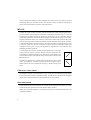
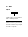
SlingShot
user manual
© 1998 - 2001 Martin Professional A/S, Denmark.
All rights reserved. No part of this manual may be
reproduced, in any form or by any means, without
permission in writing from Martin Professional A/S,
Denmark.
Printed in Denmark.
P/N 35020001, Rev. F
I NTRODUCTION
The Mach SlingShot Series has been developed for high performance touring and top-end
installation applications. The MS1262, MS15X2 and MS118 cover new pioneering ground and
incorporate several new materials and techniques, including a special horn flare design that is
acoustically optimized to eliminate eddy currents and a new construction technique that
minimizes mechanical resonance.
The SlingShot has a very high SPL-to-frontal-area/SPL-to-weight ratio and is capable of
delivering HI-FI like clarity at maximum output.
MS1262
The MS1262 is an active three-way long throw unit with a 55° x 35° coverage pattern,
operating from 190Hz to 21kHz. The 12” and 6” units are built from scratch to achieve
maximum performance in the horn-loaded design. The 12” is a fast, clean, and very strong unit
that works from 140 Hz to 2 kHz. The unit has a powerful motor with a 2 ½” voice coil with
excellent cooling and very low power compression. The 6 ½” high/mid unit is exceptionally
crisp and detailed. It features a 1 ¼” aluminum voice coil and has a very extended frequency
response from 600 Hz to 6 kHz.
The HF unit is a 2" compression driver with a 3" titanium diaphragm. To achieve an extended
frequency response, special Mylar suspension is incorporated into the unit. The solid power
handling and very low power compression is achieved by incorporating a specially developed
flat aluminum voice coil. Apart from virtually linear performance from 3 to 18 kHz, the driver
has a remarkably clean, neutral, and open sound.
All drive units in the MS1262 operate more than an octave beyond the frequency range in
which they are engaged. The audible result of this extreme approach is a speaker with
remarkable headroom and ideal phase throughout the frequency range. The nature of the
speaker remains unchanged regardless of the output and it maintains detail and clarity even at
maximum SPL.
MS15X2
The MS15X2 is a horn-loaded double 15” mid-bass unit with a horizontal beam width of 90° 120° and a vertical beam width of 50° - 90°. It delivers extreme output and clarity with a
uniform on-and-off-axis response that provides ideal support for the MS1262 and MS118 in
outdoor or large indoor live applications where more energy is needed in the critical mid-bass
area. The engine consists of two specially developed 15” low-mid devices with a shaped cone,
low hysteresis in all moving parts, and a double cooling system. They are lightly loaded by a
3
newly developed WaveShaper™, which transforms the circular wave into a square wave while
minimizing distortion and eddy currents. The MS15X2 cabinet is similar to the MS1262
cabinet, allowing both units to be flown in the same cluster.
MS118
The MS118 is built around an extremely powerful and efficient woofer designed specifically to
provide powerful and accurate bass frequencies with minimal distortion. The 5” voice-coil
assembly has probably the largest magnet ever employed in an 18” transducer and the
outstanding performance confirms the theory that there is no substitute for motor power on lowfrequency transducers of this class. Extensive research has resulted in the composite alloy-andsteel pole piece that provides stable and uniform magnetic field and improved linear excursion.
A sophisticated double suspension maintains pure axial movement, ensuring that the voice-coil
is correctly centered at all times. The motor assembly generates a high BL product that
contributes to the speed, accuracy and high fidelity reproduction, even under the most
demanding operating conditions.
A 38 mm thick driver chassis mounting board is employed to secure tight
and precise bass response. Acoustic absorption foam is used in the rear
compartment to eliminate standing waves and off-axis sound leakage. The
18 mm cabinet features front and rear flying tracks similar to those on the
MS1262 top-box.
The MS118 is designed as a symmetrically loaded half horn. When paired
with a second MS118, it should be stacked as shown to right to form a
double-sided horn with extended sub-frequency output and improved
throw.
CABINET
FEATURES
The SlingShot cabinets are constructed of 13 ply, 18 mm plywood and finished with a highly
scratch and weather resistant polyurethane coating. The MS118 bass cabinet features integrated
rubber feet for safe stacking and convenient guide lines for easy stacking.
ACCESSORIES
Transportation dollies (P/N 93941002) are available for the top-boxes. The dollies are easily
locked into the front grille and protect the speakers during transport.
Wheels with and without brakes are available for the subs (P/N 19400060 without brake, P/N
19400070 with brake).
4
I NSTALLATION
CONNECTIONS
All SlingShot models feature an 8-pole Speakon® plug. The drivers in the MS1262 and MS118
are connected as follows:
Driver
Pins
18”
1+, 1-
12”
2+, 2-
6 ½”
3+, 3-
2”
4+, 4-
The 1+, 1- pins are linked on all terminals to enable linking between subs and top-boxes.
Always use high quality speaker cable. Cables with high capacitance, high inductance and high
impedance have a negative influence on sound quality as well as amplifier performance and
reliability. We recommend the special 8-pole Mach speaker cable, which is a professional 4
mm2 rubber cable with low capacitance, inductance, and impedance.
Very long cables heavily influence sound quality and amplifier stability.
FLYING
THE SPEAKERS
The SlingShot flying system is fast, flexible and safe. There are four flying tracks on the
SlingShot cabinets: two in front, and two in back at the center that are connected by an internal
steel bracket. All flying tracks use “Double Stud and Ring” locking fittings (P/N 93944000),
which have a certified load of 2400 kilograms per fitting when mounted in the SlingShot flying
track.
The flying system allows the boxes to be flown in a straight line or in a “banana” shape,
whichever best suits the desired coverage pattern. For 2-wide flying, the ideal angle between
top boxes is 20°. For 3-wide configurations, fly the top boxes at an angle of 45°.
The tilt of each individual box is adjustable in 1° increments.
The Slingshot is compatible with ATM flying bars. For clusters of up to 12 boxes (4 wide by 3
deep), use the ATM MLDS system. For arrays of 9 to 24 boxes, use the ATM MEGS 575 flying
system.
Custom 2-wide and 3-wide fixed flying bars and a comprehensive flying manual are under
development; please inquiry about availability.
5
OPERATION
PROCESSORS/CONTROLLERS
The SlingShot operates with any four-way processor or controller. A software file is available
for the XTA DP266 and BSS Omnidrive, Omnidrive Compact and Omnidrive Compact Plus.
The file can be downloaded from the service and support area of the Mach web site at
http://www.mach.dk. For other processors or controllers, please refer to the settings in the
specifications.
The SlingShot combination MS1262 / MS118 or M182T may be operated with the Mach MS3
three-way analog controller. For three-way operation with the MS3, the MS1262 must be
rewired for passive mode operation. See “Wiring” on page 8. Power handling in three-way
(passive) mode for the 6” and the 2” in combination is 275 watts and the load is 8 ohms.
BREAK-IN
PERIOD
The SlingShot drive units are hand-made of exceptionally strong and durable materials that
must be broken in for a short period before they perform fully to specification. Each drive unit
requires approximately 10 hours of use, and subs require approximately 30 hours, to break in.
No precautions or special procedures are necessary during the break-in period.
6
SERVICE
REQUIRED
MS15X2
TOOLS
For
Tool
Access door
Torx 30
Drive units
4 mm Allen
Grille, horn flare, 12” cup, cable terminal
#2 Phillips
6 ½” phase plug
Fixed key #17
12” phase plug
Fixed key #19
SERVICE
MS15X2 CONE KIT
15” cone kit. . . . . . . . . . . . . . . . . . . . . . . . . . . . . . . . . . . . . . . . . . . . . . . . . . . . . . . . . . . . . . P/N 50304006
MS15X2 CABLE COLOR CODES
red . . . . . . . . . . . . . . . . . . . . . . . . . . . . . . . . . . . . . . . . . . . . . . . . . . . . . . . . . . . . . . . . . . . . . . . . . . . . . . 2 +
black . . . . . . . . . . . . . . . . . . . . . . . . . . . . . . . . . . . . . . . . . . . . . . . . . . . . . . . . . . . . . . . . . . . . . . . . . . . . .2 MS15X2 CROSSOVER SETTINGS
Recommended crossover points . . . . . . . . . . . . . . . . . . . . . . . . . . . . . . . . . . . . . . . 90-350Hz / 24 dB LR
Power handling . . . . . . . . . . . . . . . . . . . . . . . . . . . . . . . . . . . . . . . . . . . . . . . . . . 1000 watt RMS in 4 ohm
Delay. . . . . . . . . . . . . . . . . . . . . . . . . . . . . . . . . . . . . . . . . . . . . . . . . . . . . . . . . . . . . . . . . . . . . . . . . 1.9 ms
To access MS15X2 drive units
1
Unscrew the grille. Unscrew the horn flare screws on the cabinet sides.
2
Unscrew the access door.
3
Unscrew the internal horn flare module brackets.
4
Remove the cables from the Speakon terminal and take out the horn flare module.
7
MS1262
SERVICE
WIRING
Mode
Signal
Wire
Terminal
Red
Speakon 3+
Black
Speakon 3-
Orange
Speakon 4+
Blue
Speakon 4-
12” +
Red
Speakon 2+
12” -
Black
Speakon 2-
High input
-
Speakon 4+/4-
Upper-mid input
-
Speakon 3+/3-
Lower-mid input
-
Speakon 2+/2-
2” +
Orange
HIGH A2
2” -
Blue
HIGH A1
6½” +
Brown
LOW A
6½” -
White
LOW -
Crossover input
Active and
passive
Active
Jumper wire between HA and HA
Passive
High & upper-mid input
-
Speakon 3+/3-
Lower-mid input
-
Speakon 2+/2-
2” +
Orange
HIGH P2
2” -
Blue
HIGH P1
6½” +
Brown
LOW P
6½” -
White
LOW -
Jumper wire between HP and HP
8
To access the MS1262 2” and 6 ½” drive units
1
Unscrew the rear access door.
2
Unscrew the drive unit and lift directly out of the box.
To access the MS1262 12” drive unit
1
Unscrew the rear access door.
2
Unscrew the cup for the 12”.
3
Disconnect the cables from the 12” unit. Pull the cables out through the cup. Move the
cup to the upper part of the cabinet to ease access to the 12”.
4
Unscrew the 12” drive unit. Unscrew the phase plug.
To mount the MS1262 12” dr ive uni t
1
Mount the phase plug into the 12”. Make sure that the phase plug is placed horizontally
in the horn flare.
2
Mount the 12” into the baffle board.
3
Pull the cables through the plastic cup. Mount the cables on the terminal.
4
Mount the cup on the 12” drive unit.
To remove the MS1262 horn flare module
If all drive units needs to be serviced, it is easiest to remove the horn flare module.
1
Unscrew the grille.
2
Unscrew the horn flare screws on the cabinet sides.
3
Unscrew the access door.
4
Unscrew the four internal horn flare module brackets. Remove the horn flare module.
MS1262 CONE KITS
12” cone kit. . . . . . . . . . . . . . . . . . . . . . . . . . . . . . . . . . . . . . . . . . . . . . . . . . . . . . . . . . . . . . P/N 50304010
6 ½” drive unit . . . . . . . . . . . . . . . . . . . . . . . . . . . . . . . . . . . . . . . . . . . . . . . . . . . . . . . . . . . P/N 05862002
2” cone kit . . . . . . . . . . . . . . . . . . . . . . . . . . . . . . . . . . . . . . . . . . . . . . . . . . . . . . . . . . . . . . . P/N 50304057
9
MS118 service
MS18 CONE KIT
18” cone kit . . . . . . . . . . . . . . . . . . . . . . . . . . . . . . . . . . . . . . . . . . . . . . . . . . . . . . . . . . . . . . P/N 50304011
MS18 CABLE COLOR CODES
red . . . . . . . . . . . . . . . . . . . . . . . . . . . . . . . . . . . . . . . . . . . . . . . . . . . . . . . . . . . . . . . . . . . . . . . . . . . . . .1 +
black. . . . . . . . . . . . . . . . . . . . . . . . . . . . . . . . . . . . . . . . . . . . . . . . . . . . . . . . . . . . . . . . . . . . . . . . . . . . . 1 -
To access MS118 dri ve units
10
1
Unscrew the access door.
2
Remove the cables from the Speakon terminal.
3
Unscrew the drive unit.
TECHNICAL
DATA
MS1262
MS15X2
MS118
Power rating, AES/Program
12”: 350/700W
6½”: 125/250W
2”: 140/280W
800/2000 W
600/1700W
Frequency response (+/- 3dB)
12”: 160-2kHz
6½”: 600-8kHz
2”: 800-18kHz
90-650Hz
59-220Hz
52-220Hz (2 pcs.)
Recommended crossover points
12”: 190-1.3kHz
6½”: 1.3-3.6kHz
2”: 3.6kHz-infinity
90-350Hz
39-190Hz
Delay settings
(measured when ground stacking)
2.28ms
1.9ms
none
Maximum SPL
137dB
135dB
132dB
135dB (2 pcs.)
Sensitivity (W/m)
12”: 106dB
6½”: 106dB
2”: 108dB
105dB
103dB
Nominal impedance
12”:8 ohm
6½”: 8 ohm
2”: 16 ohm
4 ohm
8 ohm
Dispersion/beamwidth
55x35°
90-120° Horz.
60-90° Vert.
-
Q/DI
26/14dB
26/14dB
-
Dimensions (HxWxD)
82x59x72.5 cm
(32x23x28.5 in.)
82x59x72.5 cm
(32x23x28.5 in.)
76.5x59x72.5 cm
(26.5x23x28.5 in.)
Weight
68 kg
(150 lbs.)
70 kg
(154 lbs.)
65 kg
(143 lbs.)
Martin Professional A/S • Olof Palmes Allé 18 • 8200 Aarhus N • Denmark
www.martin.dk