1
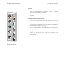
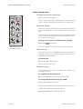
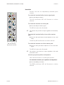
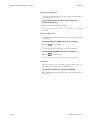
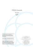
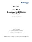
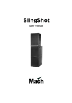
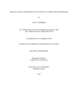
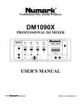
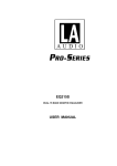
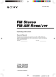
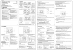
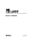
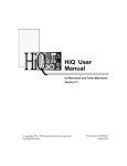
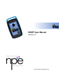
VR Legend Console
THE VRL CONSOLE SURFACE
The VRL Channel Strip
Input Filters
31.5
These are 12dB/octave high and low pass filters, with
frequency ranges from 31.5Hz to 315Hz and 7.5kHz to
18kHz respectively.
80
The filters can be switched into the channel path
independently.
kHz7.5 18
13 315
8
9
pull
FILT
Hz
50
10240
150
Channel Strip
Input Filter Module
Dynamic Control
Full limiter/compressor and gate/expander facilities are
available with a fully flexible sidechain (each of which can
be individually switched in or out of circuit).
KEY
L/C
INV
HYST25
EXP
GAIN
0
5 30
20
6
15 10 24
THR
+15
-25 18 12
THR
-17 -10 +20
+7
0
pull
20
30
40
10
+14
-10 -4
-30
+2
+8
3
pull
-20
5
50 2
pull RGE
.3
0
li
m
1
FAST
RAT pull
0.3 FAST
.
0 03
3s
REL
.
GATE 0 03 REL 3s
AUTO
0
Channel Strip
Dynamics Module
The gate/expander has rotary controls for a 50dB gate
range, a 70dB threshold range, release from 30ms to 3s,
switchable attack time and variable hysteresis.
Hysteresis makes the threshold level different for signals
which are rising or falling in level and allows precise
triggering on the wanted signal while still allowing the
correct amount of signal ‘tail’ through.
The expander has a 2:1 expansion ratio.
Switched controls are provided for an external key input and
invert (for ducking). The external key input is accessed from
the patchbay.
The limiter/compressor has rotary controls for release times
from 30ms to 3s with an end stop, a 50dB threshold range,
a ratio of 1:1 to limiting and up to 30dB of gain make-up.
Attack time is program dependent with a switch for fast
impulse response.
The Release control incorporates a switch for automatic
programme dependent release.
‘Anti pumping and breathing’ circuitry allows the unit to
operate on the source musically whilst retaining absolute
control over the dynamic range.
The equaliser module can be inserted into the sidechain of
the dynamics module for de-essing, etc.
Issue 3
VRL User Manual 3:3
THE VRL CONSOLE SURFACE
The VRL Channel Strip
Inserts
INS
PREQ
1.5
17
3
11
DYN
Inserts can be positioned in either the channel or monitor
path independently of the equaliser.
Pre-equaliser and pre-dynamics configuration is also
possible.
4.7
kHz 7
Formant Spectrum Equalisers
HI-Q
8.7
0.8
The unique sound of AMS Neve equalisers is the result of
years of research and extensive studio experience.
1.4
5.6
kHz 3.6
2.3
The equaliser provides 4-band parametric equalisation,
with overlapping frequency ranges.
The two mid-bands have variable controls for Q (from 0.5
to 9), gain (18dB cut and boost) and frequency.
Q
2k
190
360
1k4
Hz 870
Q
580
HI-Q
370
33
The high and low frequency controls provide variable gain
(18dB cut and boost) and frequency controls with
switchable Q (either 0.71 to 2) and peaking/shelving
characteristic.
63
240
Hz 150
100
EQ
Channel Strip
Equalisation Module
Issue 3
VRL User Manual 3:5
PROCESSING (DYNAMICS and EQ)
Gate/Expander
Gate/Expander
To enable the Gate/Expander
KEY
! Press the GATE push-button on the dynamics module.
L/C
INV
HYST25
EXP
The GATE push-button LED will illuminate and the
Gate/Expander is placed in the signal path.
GAIN
0
5 30
20
6
15 10 24
THR
+15
-25 18 12
THR
-17 -10 +20
+7
+14
0 -10 -4
External Gate/Expander Trigger
To enable the gate to be triggered by an external
device or any other path signal
pull
-30
20
30
40
10
+2
+8
3
pull
! Press the KEY push-button.
-20
The KEY push-button LED will illuminate.
5
50 2
RGE
.
1 RAT lim
FAST 0 3
pull
0.3 FAST
0.03
3s
REL
.
GATE 0 03 REL 3s
AUTO
pull
0
A dedicated patch input to the Gate/Expander is provided.
The compressor operation is not affected.
Invert
VRL Channel Strip
Dynamics Module
Allows the user to close the gate when a signal of the
required level is present.
Used as a ‘ducker’ (i.e. cutting out background noise) or for
muting severe breakthrough from another source.
To close the gate when a signal of the required
level is present
(i.e. invert the external trigger control)
! Press the INV push-button.
The INV push-button LED will illuminate.
Hysteresis
Hysteresis is the difference in dB between the muted gate
level and its un-muted level. Varying the hysteresis allows
more precise triggering of the wanted signal while at the
same time allowing the correct amount of signal tail to pass
through.
"
10dB of hysteresis is a good starting value for setting the gate.
To adjust hysteresis
! Turn the HYST rotary control.
Hysteresis is present at all times.
To switch the circuit into a 2:1 ratio expander
! Turn the HYST rotary control to the EXP position (i.e. fully
anti-clockwise).
Issue 3
VRL User Manual 7:3
Gate/Expander
PROCESSING (DYNAMICS and EQ)
Threshold
Provides threshold control over 70dB in two overlapping
ranges.
To set the difference in dB between the muted gate
level and its un-muted level
! Turn the THR rotary control to the desired value.
To change the threshold range by -30dB
! Pull up the THR rotary control.
The associated red LED will illuminate to confirm the action.
-30dB will be added to the panel values.
! Adjust the THR rotary control as desired.
Gate range (mute depth)
Allows users to set the range (mute depth) of the gate over a
50dB range.
To set the range of the gate
! Turn the RGE rotary control to the desired value.
To change the attack time from 1ms to 100us
! Pull up the RGE rotary control.
Gate/expander release time
The release time for the gate/expander is continuously
variable from 30ms to 3s.
To set the gate/expander release time
! Adjust the REL rotary control as desired.
VRL User Manual 7:4
Issue 3
PROCESSING (DYNAMICS and EQ)
Limiter/Compressor
Limiter/Compressor
To enable the Limiter/Compressor
KEY
! Press the L/C push-button.
L/C
INV
HYST25
EXP
The L/C push-button LED will illuminate to confirm selection
and the Limiter/Compressor is placed in the signal path.
GAIN
0
5 30
20
6
15 10 24
THR
+15
-25 18 12
THR
-17 -10 +20
+7
+14
0 -10 -4
pull
-30
20
30
40
10
+2
+8
3
pull
-20
5
50 2
RGE
.
1 RAT lim
FAST 0 3
pull
0.3 FAST
0.03
3s
REL
.
GATE 0 03 REL 3s
AUTO
pull
0
VRL Channel Strip
Dynamics Module
Stereo pair linking
Allows the user to link the limiter/compressor to the module
located immediately to its right-hand side, forming a stereo
pair.
The link can also be made if the limiter/compressor is not in
circuit (so that it can be used for a stereo/quad link even if it
is not actively processing).
To form a stereo pair or establish quad ganging
! Press the
push-button.
The associated LED will illuminate to confirm selection.
Gain make up
Gain make-up of up to 30dB allows the user to maintain an
optimum signal to noise ratio throughout the path (even
under heavy compression).
To adjust gain
! Turn the GAIN rotary control.
Gain is present at all times.
Threshold ranges
The threshold level can be controlled over 50dB in two
overlapping ranges.
To establish the threshold level
! Turn the THR rotary control to the desired value.
To change the threshold range by -20dB
! Pull up the THR rotary control.
The associated red LED will illuminate to confirm the action.
-20dB will be added to the panel values.
! Adjust the THR rotary control as desired.
Issue 3
VRL User Manual 7:5
Limiter/Compressor
PROCESSING (DYNAMICS and EQ)
Compression Ratio
Allows users to select the compression ratio with an
arranged law between 1:1 and limiting (1 and lim).
To establish the compression ratio
! Turn the RAT rotary control to the desired value.
To change the attack time from 1ms to 100us
! Pull up the RAT rotary control.
"
Pulling up the ratio control nominally increases the impulse
attack time from 1ms to 100us, however the attack time is
actually programme dependent, normally having a 7ms time
constant (with faster time constants applied to transient
programme material).
Release time
Allows users to establish the release time from 30ms to 3s
with automatic ‘hold’ and impulse release circuits to
remove pumping and breathing effects.
To adjust the release time
! Turn the REL rotary control to the desired position.
To switch the release control to a triple time
constant programme dependent release time
! Turn the REL rotary control in a clockwise direction until it
can not be turned any further (i.e. 3s).
VRL User Manual 7:6
Issue 3
PROCESSING (DYNAMICS and EQ)
Insertion
Insertion
INS
Provides users with an independently switchable patch
insertion.
PREQ
1.5
17
3
11
kHz 7
To switch the insertion facility into the signal path
DYN
4.7
! Press the INS push-button.
0.8
The INS push-button LED will illuminate to confirm
selection.
HI-Q
8.7
1.4
5.6
kHz 3.6
2.3
To switch the insertion out of the path
! Press the INS push-button again.
The LED will cease to be illuminated.
Q
2k
190
360
1k4
Hz 870
Q
"
580
To switch the insertion facility in/out of the monitor
path
HI-Q
370
33
63
240
Hz 150
The insertion will provide an output regardless of the INS key
state.
! Press the INS push-button located adjacent to the small
fader.
100
EQ
The INS key LED will illuminate to confirm selection.
To switch the insertion out of the monitor path
VRL Channel Strip
Equalisation Module
! Press the INS push-button adjacent to the small fader
again.
The LED will cease to be illuminated.
"
The insertion will provide an output regardless of the INS
push-button state.
Insertion pre/post-equaliser and dynamics
When selected insertion is normally post-equaliser.
To switch the insertion pre-equaliser and dynamics
! Press the PREQ push-button.
The PREQ push-button LED will illuminate to confirm
selection.
Issue 3
VRL User Manual 7:7
Equaliser
PROCESSING (DYNAMICS and EQ)
Equaliser
INS
PREQ
The equaliser consists of four continuously-variable
overlapping frequency bands with a peaking characteristic.
DYN
Users can switch from peak to shelving.
1.5
17
3
11
4.7
kHz 7
Frequency control ranges
HI-Q
8.7
0.8
Low:
Mid1:
Mid2:
High:
1.4
5.6
kHz 3.6
2.3
33Hz to 370Hz
190Hz to 2kHz
0.8kHz to 8.7kHz
1.5kHz to 17kHz
Q varies with gain
Q
2k
360
1k4
Hz 870
Q automatically varies with gain on all bands in peaking
and shelving modes (as gain is increased so is Q).
190
Q
580
HI-Q
370
33
Rotary controls
The tops of the rotary controls EQ_module are colour
coded to distinguish the controls for each band of EQ.
63
240
Hz 150
100
EQ
VRL Channel Strip
Equalisation Module
Low
Mid1
Mid2
High
Black
Light grey
Pale blue
Orange
To switch the equaliser into the circuit
! Press the EQ push-button.
The integral LED will illuminate to confirm selection.
! Adjust EQ frequency as desired using the rotary controls.
Mid Band Q
The mid band equalisers (pale blue and light grey rotary
controls) have variable Q adjusted across a range of 0.5 to
9.
The rotary controls have a centre detent at Neve FSE
traditional settings.
To adjust mid band Q
! Turn the Q rotary controls to the desired position.
VRL User Manual 7:8
Issue 3
PROCESSING (DYNAMICS and EQ)
Equaliser
High and Low Band Q
The Q and characteristics of the high and low bands can be
switched from 0.71 to 2.
To switch the Q and characteristics of high/low
bands from 0.71 to 2
! Press the desired HiQ push-button.
The HiQ push-button LED will illuminate to confirm
selection.
Peak and Shelving
The high and low band equalisers are switchable from peak
to shelving.
To switch high band EQ from peak to shelving
! Press
the push-button.
The integral LED will illuminate to confirm selection.
To switch low band EQ from peak to shelving
! Press
the push-button.
The integral LED will illuminate to confirm selection.
Cut/Boost
All four bands have a smooth rotary control each for
adjusting cut or boost over an 18dB range.
To adjust cut or boost in an equaliser band
! Turn the appropriate cut/boost rotary control to the desired
position.
Issue 3
VRL User Manual 7:9
Sidechain Equalising
PROCESSING (DYNAMICS and EQ)
Sidechain Equalising
Allows users to insert the module equaliser into the control
Sidechain of the dynamics unit.
To insert the equaliser into the control sidechain of the
dynamics unit
! Press the DYN push-button in the equaliser module.
The DYN push-button LED will illuminate to confirm
selection.
VRL User Manual 7:10
Issue 3