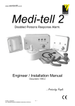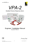
1
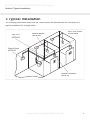
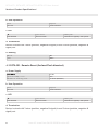
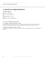
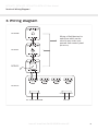
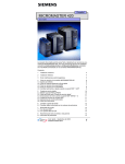
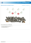
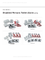
DPTA-KIT1, DPTA-KIT2, DPTA-KIT3 & DPTA-KIT4 User Manual
User Manual /
Disabled Persons Toilet Alarm (DPTA)
DPTA-KIT1
DPTA-KIT2
DPTA-KIT3
DPTA-KIT4
Issue #1 Issue Date 26/09/2008 Revision #5
DPTA-KIT1, DPTA-KIT2, DPTA-KIT3 & DPTA-KIT4 User Manual
Contents /
Contents
2
Section 1 Introduction
3
Section 2 Features
4
Section 3 Typical Installation
5
Section 4 Product Specifications
6
Section 5 Electrical Requirements
10
Section 6 Wiring Diagram
11
Issue #1 Issue Date 26/09/2008 Revision #5
DPTA-KIT1, DPTA-KIT2, DPTA-KIT3 & DPTA-KIT4 User Manual
Section 1 Introduction /
1 Introduction
This Disabled Persons Toilet Alarm Kit is available in 1, 2, 3 or 4 zones (where one zone is used
for each toilet). It has been designed for use in disabled persons dwellings typically for disabled
toilets where this design process considered the requirements of BS8300.
The system consists of a 4 zone control panel (DPTA-CP4) which is (for each zone) connected
to a Pull Cord (DPTA-PC), Remote Reset (DPTA-RR) and Remote Indicator (DPTA-RI). These
connected items are known as field devices which provide the Control Panel with the necessary
input and output signals to allow the system to function. These field devices are categorised as
follows;
Pull Cords (DPTA-PC) are “Call Devices” which are ceiling
mounted pull cords used to generate an alarm activation
by a person in distress or requiring attention from a
carer. When a call devices is activated the system will
generate an alarm and the Remote Indicator (DPTA-RI)
will illuminate & sound.
Remote Resets (DPTA-RR) are “Reset Devices” which are
generally wall mounted and consist of a push button
which is pressed to cancel an alarm activation.
Remote Indicators (DPTA-RI) are “Warning Devices”
that are generally wall mounted devices which during
an alarm activation will alert cares / staff of a person
requiring attention. Warning devices typically have
visual and audible element within the same housing,
but devices with only audible or visual elements may be
fitted to a system.
The control panel (DPTA-CP) is powered by mains supply
and an optional battery back-up can be installed which
allows the system to function during a power outage.
Issue #1 Issue Date 26/09/2008 Revision #5
3
DPTA-KIT1, DPTA-KIT2, DPTA-KIT3 & DPTA-KIT4 User Manual
Section 2 Features /
2 Features
Simple 3 wire operation for all field devices
Control Panel supporting up to 4 zones
Simple maintenance and fault diagnosis.
On board buzzer in both Control Panel & Remote Indicator
Zone LED indication on Control Panel
Full range of field devices available (i.e. Pull Cord, Remote Reset & Remote Indicator)
System silence/mute option from Control Panel
Local (at Control Panel) or remote (at Remote Reset) reset options
Optional battery back-up
Auto shut down function to save battery power
4
Issue #1 Issue Date 26/09/2008 Revision #5
DPTA-KIT1, DPTA-KIT2, DPTA-KIT3 & DPTA-KIT4 User Manual
Section 3 Typical Installation /
3 Typical Installation
The following illustration shows how the Control Panel and field devices are connected in a
typical installation for a single toilet;
Pull Cord
(DPTA-PC)
Up to four toilets
on one panel
Remote Resets
(DPTA-RR)
Control Panel
(DPTA-CP)
Remote Indicators
(DPTA-RI)
Issue #1 Issue Date 26/09/2008 Revision #5
5
DPTA-KIT1, DPTA-KIT2, DPTA-KIT3 & DPTA-KIT4 User Manual
Section 4 Product Specifications /
4 Product Specifications
4.1 DPTA-CP – Control Panel (Surface/Flush Mounted)
a. Power Supply
Mains Input Voltage
230VAC 50Hz/60Hz
Quiescent Standby Current
3mA DC (Buzzer Muted)
Maximum Overall Supply Current
250 mA DC (Maximum)
DC Input Voltage
12VDC Battery
b Button Functions
Button
System Status
Operation
Function
Silence
Alarm Activation
Press for 0.5 Seconds
Mute Control Panel
Reset
Alarm Activation
Press for 0.5 Seconds
Rest All Zones
Zone 1
Alarm Activation
Press for 0.5 Seconds
Reset Zone 1
Zone 2
Alarm Activation
Press for 0.5 Seconds
Reset Zone 2
Zone 3
Alarm Activation
Press for 0.5 Seconds
Reset Zone 3
Zone 4
Alarm Activation
Press for 0.5 Seconds
Reset Zone 4
c. Led’s
LED
System Status
LED Response
Mains - Green
Mains On
Constant: Mains Present
Battery Back-Up
Pulse Every 5 Seconds
Battery Saver Pulse
Every 20 Seconds
Alarm Activation
Slow Flashing – 1.Hz
Alarm (Zone 1, 2, 3, 4) - Red
d. Internal Buzzer
Type
Piezo (PCB Mounted)
Current
5mA maximum
Frequency
1 Khz Tone
Sound
1 Hz Pulse (Alarm Activation)
Mute (System Normal)
Beep Every 20 Seconds (Battery Saver Mode)
6
Issue #1 Issue Date 26/09/2008 Revision #5
DPTA-KIT1, DPTA-KIT2, DPTA-KIT3 & DPTA-KIT4 User Manual
Section 4 Product Specifications /
e. Field Device Inputs
Number of Zone Circuits
Detection Supply
Detection Mode Monitoring
1
Voltage
12 VDC +/- 10%
Maximum Current
30mA
Short Circuit
> 30mA
Open Circuit
< 1.5mA
f. Field Device Outputs
Number of Zone Circuits
Sounder Supply
Alarm
1
Voltage
12 VDC +/- 10%
Maximum Current
200mA
Protection
Shut Down At
Call
1 Hz Pulse
g. Battery Input
Charging Voltage
13.8 VDC
Deep Discharge Protection
Less than 10.5 VDC
h. Fuses
F1: Auxiliary
500mA Anti Surge 20mm Glass
F2: Battery
500mA Anti Surge 20mm Glass
i. Housing
Front Cover
Polycarbonate – Fire Retardant
Back Box
Polycarbonate – Fire Retardant
Maximum Current During Alarm
30 mA DC (Maximum)
4.2 DPTA-PC – Pull Cord (Ceiling Mounted)
a. Power Supply
Input Voltage
12 VDC
Quiescent Standby Current
0mA
Maximum Current During Alarm
15 mA DC (Maximum)
Issue #1 Issue Date 26/09/2008 Revision #5
7
DPTA-KIT1, DPTA-KIT2, DPTA-KIT3 & DPTA-KIT4 User Manual
Section 4 Product Specifications /
b. User Operation
Action
Response
Pull Card
Alarm Activation
c. LED
LED
System Status
LED Response
Front Mounted
Alarm Activation
Illuminates in Sympathy with System
d. Termination
Device is wired with 3 wires (positive, negative & signal) in and 3 wires (positive, negative &
signal) out.
e. Housing
Material
ABS
Colour
White
4.3 DPTA-RR – Remote Reset (Surface/Flush Mounted)
a. Power Supply
Input Voltage
12 VDC
Quiescent Standby Current
0mA
Maximum Current During Alarm
15 mA DC (Maximum)
b. User Operation
Action
Response
Pull Card
Alarm Activation
c. LED
LED
System Status
LED Response
Front Mounted
Alarm Activation
Illuminates in Sympathy with System
d. Termination
Device is wired with 3 wires (positive, negative & signal) in and 3 wires (positive, negative &
signal) out.
8
Issue #1 Issue Date 26/09/2008 Revision #5
DPTA-KIT1, DPTA-KIT2, DPTA-KIT3 & DPTA-KIT4 User Manual
Section 4 Product Specifications /
e. Housings
Material
ABS
Colour
White
4.4 DPTA-RI – Remote Indicator (Surface/Flush Mounted)
a. Power Supply
Input Voltage
12 VDC
Quiescent Standby Current
0mA
Maximum Current During Alarm
30 mA DC (Maximum)
c. LED
LED
System Status
LED Response
Front Mounted
Alarm Activation
Illuminates in Sympathy with System
d. Termination
Device is wired with 3 wires (positive, negative & signal) in and 3 wires (positive, negative &
signal) out.
e. Housings
Material
ABS
Colour
White
Issue #1 Issue Date 26/09/2008 Revision #5
9
DPTA-KIT1, DPTA-KIT2, DPTA-KIT3 & DPTA-KIT4 User Manual
Section 5 Electrical Requirements /
5 Electrical Requirements
A. Power Supply
230V AC at 50/60Hz
12V DC Storage battery
Standby Current : 4mA
Alarm Current : 250mA (max)
B. DPTA-CP Internal Safety Fuses
F1 - Auxiliary – 500mA, Anti Surge / Timed.
The Auxiliary Fuse protects the DPTA-CP circuitry, field devices and field device wiring from
current overload. The field device wiring is protected with electronic current limiting.
F2 – Battery – 500mA, Anti Surge / Timed.
The battery fuse protects the DPTA-CP battery supply from overload either while charging or in
standby.
10
Issue #1 Issue Date 26/09/2008 Revision #5
DPTA-KIT1, DPTA-KIT2, DPTA-KIT3 & DPTA-KIT4 User Manual
Section 6 Wiring Diagram /
6 Wiring Diagram
DPTA-RR
Wiring of field devices for
each zone which can be
wired in any order once
spurred from control panel
(DPTA-CP)
DPTA-RI
DPTA-PC
DPTA-CP
L
N
AC 230V 50/650Hz
BAT+
BAT-
12V DC
Issue #1 Issue Date 26/09/2008 Revision #5
11