1
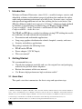
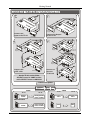
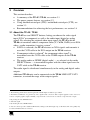
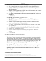
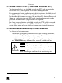
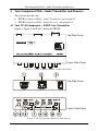
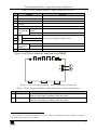
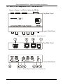
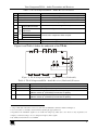
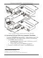
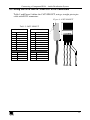
Kramer Electronics, Ltd.
USER MANUAL
Models:
TP-45, Component/XGA – Audio Transmitter
TP-46, Component/XGA – Audio Receiver
Contents
Contents
1
2
2.1
3
3.1
3.2
3.3
3.4
4
4.1
4.2
5
5.1
5.2
5.3
6
Introduction
Getting Started
Quick Start
Overview
About the TP-45 / TP-46
About the Power Connect Feature
Shielded Twisted Pair (STP) / Unshielded Twisted Pair (UTP)
Recommendations for Achieving the Best Performance
Your Component/XGA – Audio Transmitter and Receiver
Your TP-45 Component – S/PDIF Line Transmitter
Your TP-46 Component/XGA – Audio Receiver
Connecting a Component/XGA – Audio Distribution System
Connecting TP-45 and TP-46 in the XGA Mode
Connecting TP-45 and TP-46 in the Component Video Mode
Wiring the CAT5 LINE IN / LINE OUT RJ-45 Connectors
Technical Specifications
1
1
1
3
3
4
5
5
6
6
8
10
10
12
15
16
Figures
Figure 1: TP-45 Component/XGA – Audio Transmitter
Figure 2: TP-45 (Top Side and Lower Side Panels)
Figure 3: TP-45 Component/XGA – Audio Transmitter (Underside)
Figure 4: TP-46 Component/XGA – Audio Receiver
Figure 5: TP-46 (Top Side and Lower Side Panels)
Figure 6: TP-46 Component/XGA – Audio Receiver (Underside)
Figure 7: Component/XGA – Audio Distribution System, XGA Mode
Figure 8: Component/XGA – Audio Distribution System, Component Video Mode
Figure 9: CAT5 PINOUT
6
6
7
8
8
9
12
14
15
Tables
Table 1: TP-45 Component/XGA – Audio Transmitter Features
Table 2: TP-45 Component/XGA – Audio Transmitter (Underside) Features
Table 3: TP-46 Component/XGA – Audio Receiver Features
Table 4: TP-46 Component/XGA – Audio Receiver (Underside) Features
Table 5: CAT5 PINOUT
Table 6: Technical Specifications of the TP-45 / TP-46
7
7
9
9
15
16
i
Introduction
1
Introduction
Welcome to Kramer Electronics (since 1981): a world of unique, creative and
affordable solutions to the infinite range of problems that confront the video,
audio and presentation professional on a daily basis. In recent years, we have
redesigned and upgraded most of our line, making the best even better! Our
500-plus different models now appear in 8 Groups1, which are clearly defined
by function. Congratulations on purchasing your Kramer TOOLS TP-45
Component/XGA – Audio Transmitter and Kramer TOOLS TP-46
Component/XGA – Audio Receiver.
The TP-45 and TP-46 are suitable for utilizing existing UTP cabling that results
in an efficient, fast and uncluttered environment for:
Presentation and multimedia applications
Long range graphics distribution for schools, hospitals, security, and stores
Security and military applications
The package includes the following items:
TP-45 and/or TP-46
Power adapter (12V DC Input)
This user manual2
2
Getting Started
We recommend that you:
Unpack the equipment carefully and save the original box and packaging
materials for possible future shipment
Review the contents of this user manual
Use Kramer high performance high resolution cables3
2.1 Quick Start
This quick start chart summarizes the basic setup and operation steps.
1 GROUP 1: Distribution Amplifiers; GROUP 2: Video and Audio Switchers, Matrix Switchers and Controllers; GROUP 3:
Video, Audio, VGA/XGA Processors; GROUP 4: Interfaces and Sync Processors; GROUP 5: Twisted Pair Interfaces;
GROUP 6: Accessories and Rack Adapters; GROUP 7: Scan Converters and Scalers; and GROUP 8: Cables and Connectors
2 Download up-to-date Kramer user manuals from the Internet at this URL: http://www.kramerelectronics.com
3 The complete list of Kramer cables is on our Web site at http://www.kramerelectronics.com
1
Getting Started
1
2
Plasma
Display
Connect the
Input to the TP-45
Connect the Output
to the TP-46
DVD Player
4
3
Plasma
Display
Plasma
Display
To the next
TP-46 unit
Plasma
Display
Connect the
CAT5 cable
Connect to
the next
TP-46 unit
DVD Player
On the TP-45, set the Video
SELECT button to COMP and the
audio SELECT button to ANALOG
DVD Player
Connect the power
AUDIO
TP-45
Analog
Audio
VIDEO
TP-46
Analog Audio
and/or S/PDIF
S/PDIF
2
TP-46
Component
Video
Component
Video
XGA
XGA
COMP
ANALOG AUDIO
S/PDIF
TP-45
Analog Audio
and/or S/PDIF
XGA
KRAMER: SIMPLE CREATIVE TECHNOLOGY
Overview
3
Overview
This section describes:
A summary of the TP-45 / TP-46, see section 3.1
The power connect feature, see section 3.2
Using shielded twisted pair (STP) / unshielded twisted pair (UTP), see
section 3.3
Recommendations for achieving the best performance, see section 3.4
3.1 About the TP-45 / TP-46
The TP-45 has two SELECT buttons, letting you choose the video signal
input (XGA1 or component) as well as the audio input (digital or analog
signal). By selecting the required video input signal, the TP-45 with the
TP-46 can constitute either a component video (Y, CB/PB, CR/PR) or an XGA
video – audio transmitter / receiver system2:
If XGA is selected3, the TP-45 receives an XGA signal4 and transmits it
over the CAT5 cable to the XGA output on the TP-46 receiver
If component video is selected5, the component video signal4 is
transmitted over the CAT5 cable to the COMP outputs on the TP-46
receiver
The analog audio or S/PDIF (digital audio) — as selected via the audio
SELECT button — is transmitted together with the video signal over the
CAT5 cable to the TP-46 receiver
The audio signal is distributed simultaneously to the analog and digital audio
outputs.
Additional TP-46 units can be connected via the TP-46 LINE OUT CAT5
connector, to extend the range of the output signals6.
1 The terminology XGA that is used throughout this manual implies resolutions up to UXGA
2 The TP-45 and TP-46 do not perform any video signal format conversion. Thus computer graphics sources need to be
routed to computer graphics outputs. Similarly, component video sources need to be routed to component video outputs
3 By pressing the video SELECT button
4 And audio signal
5 By releasing the video SELECT button
6 You can connect up to three additional TP-46 units, adding a total cable length of up to 300 meters. The video quality may
be reduced if further units are connected
3
Overview
The TP-45 Component/XGA – Audio Transmitter:
Has a transmission range of more than 300 ft. (more than 100 meters)
Includes a YUV1 input on 3 RCA connectors and an XGA input on an
HD15F connector
Includes a digital audio input (S/PDIF) on an RCA connector and a stereo
analog input on a 3.5mm mini jack
Can power or be powered by the receiver over the same CAT5 cable (see
section 3.2)
Is 12VDC fed
The TP-46 Component/XGA – Audio Receiver:
Has a YUV1 output on 3 RCA connectors and an XGA output on an
HD15F connector
Includes a digital audio output (S/PDIF) on an RCA connector and a
stereo analog output on a 3.5mm mini jack
Can power or be powered by the transmitter over the same CAT5 cable
(see section 3.2)
Can change the polarity of decoding H and V Sync for XGA graphics
Includes EQ. and LEVEL controls
Features a CAT5 output for transmitting the signal to an additional
receiver
Is 12VDC fed
3.2 About the Power Connect Feature
The Power Connect feature lets you power a transmitter / receiver system by
connecting just one power adapter— to either the transmitter or the receiver2.
The other unit is fed via the cable connecting between the transmitter/receiver.
The Power Connect feature applies as long as the cable can carry power. The
distance does not exceed 50 meters on standard CAT5 cable, for longer
distances, heavy gauge cable should be used3.
For a CAT5 cable exceeding a distance of 50 meters, separate power supplies
should be connected to the transmitter and to the receiver simultaneously.
Both units can be powered from the Kramer MultiTOOLS® PT-1PS CAT5
Power Supply.
1 Also known as Y, Cb, Cr, or Y, B-Y, R-Y, or Y, Pb, Pr
2 It is recommended to power the receiver (TP-46) when connecting just one power adapter
3 CAT5 cable is still suitable for the video/audio transmission, but not for feeding the power at these distances
4
KRAMER: SIMPLE CREATIVE TECHNOLOGY
Overview
3.3 Shielded Twisted Pair (STP) / Unshielded Twisted Pair (UTP)
The decision whether to use shielded twisted pair (STP) cable or unshielded
twisted pair (UTP) cable depends on the nature of the application.
It is recommended that in applications with high interference, shielded twisted
pair (STP) cable is used. However, the shield itself does create a capacitance
that degrades the frequency response of the machines. For shorter distances, of
50m or so, shielded twisted pair (STP) cable is preferred because it provides
protection from interference (degradation is non apparent).
For a long-range application, unshielded twisted pair (UTP) cable is preferred.
However, the unshielded twisted pair (UTP) cable should be installed far away from
electric cables, motors and so on, which are prone to create electrical interference.
3.4 Recommendations for Achieving the Best Performance
To achieve the best performance:
Connect only good quality connection cables, thus avoiding interference,
deterioration in signal quality due to poor matching, and elevated noiselevels (often associated with low quality cables)
Avoid interference from neighboring electrical appliances and position
your TP-45/TP-46 away from moisture, excessive sunlight and dust
Caution – No operator-serviceable parts inside unit.
Warning – Use only the Kramer Electronics input power
wall adapter that is provided with this unit1.
Warning – Disconnect power and unplug unit from wall
before installing or removing device or servicing unit.
1 For example: model number AD2512C, part number 2535-000251
5
Your Component/XGA – Audio Transmitter and Receiver
4
Your Component/XGA – Audio Transmitter and Receiver
This section describes the:
TP-45 Component/XGA – Audio Transmitter, see section 4.1
TP-46 Component/XGA – Audio Receiver, see section 4.2
4.1 Your TP-45 Component – S/PDIF Line Transmitter
Figure 1, Figure 2 and Table 1 define the TP-45:
Top Side Panel
Lower Side Panel
Figure 1: TP-45 Component/XGA – Audio Transmitter
Top Side Panel
Lower Side Panel
Figure 2: TP-45 (Top Side and Lower Side Panels)
6
KRAMER: SIMPLE CREATIVE TECHNOLOGY
Your Component/XGA – Audio Transmitter and Receiver
Table 1: TP-45 Component/XGA – Audio Transmitter Features
#
1
2
3
4
5
6
INPUTS
7
Feature
XGA IN HD15F Connector
LINE OUT RJ-45 Connector
12V DC
ANALOG AUDIO 3.5mm Mini
connector
S/PDIF RCA Connector
SELECT Audio ANALOG
Input Selector AUDIO
Button
S/PDIF
Y RCA Connector
8
9
10
11
CB/PB RCA Connector
Function
Connect to the XGA source
1
Connect to the LINE IN connector on the TP-46
+12V DC connector for powering the unit
Connect to the stereo analog audio source
Connect to the digital audio source
Release to transmit analog audio
Press to transmit digital audio
Connect to the component video source
CR/PR RCA Connector
SELECT Video COMP
Input Selector XGA
Button
ON LED
Release to transmit component video
Press to transmit XGA
Lights when receiving power
Figure 3 and Table 2 define the underside of the TP-45:
Figure 3: TP-45 Component/XGA – Audio Transmitter (Underside)
Table 2: TP-45 Component/XGA – Audio Transmitter (Underside) Features
1
#
Feature
VS Switch
2
HS Switch
Function
Slide the switch up2 (to NEG.) to change the VS polarity to negative polarity;
slide the switch down (to NORM) to retain the polarity
Slide the switch up2 (to NEG.) to change the HS polarity to negative polarity;
slide the switch down (to NORM) to retain the polarity
1 Using a straight pin to pin UTP cable with RJ-45 connectors at both ends (the PINOUT is defined in Table 5 and Figure 9)
2 By default, both switches are set to NORM
7
Your Component/XGA – Audio Transmitter and Receiver
4.2 Your TP-46 Component/XGA – Audio Receiver
Figure 4, Figure 5 and Table 3 define the TP-46:
Top Side Panel
Lower Side Panel
Figure 4: TP-46 Component/XGA – Audio Receiver
Top Side Panel
Lower Side Panel
Figure 5: TP-46 (Top Side and Lower Side Panels)
8
KRAMER: SIMPLE CREATIVE TECHNOLOGY
Your Component/XGA – Audio Transmitter and Receiver
Table 3: TP-46 Component/XGA – Audio Receiver Features
6
7
8
9
10
11
Feature
XGA OUT HD15F Connector
LINE IN RJ-45 Connector
LINE OUT RJ-45 Connector
12V DC
ANALOG AUDIO
3.5mm Mini connector
S/PDIF RCA
Connector
Y RCA Connector
CB/PB RCA Connector
CR/PR RCA Connector
ON LED
LINK LED
OUTPUTS
#
1
2
3
4
5
Function
Connect to the XGA acceptor
1
Connect to the LINE OUT RJ-45 connector on the TP-45
1
Connect to the LINE IN connector on an additional TP-46
+12V DC connector for powering the unit
Connect to the stereo analog audio acceptor
Connect to the digital audio acceptor
Connect to the component video acceptor
Lights when receiving power
Lights when receiving the correct input signal
Figure 6 and Table 4 define the underside of the TP-46:
Figure 6: TP-46 Component/XGA – Audio Receiver (Underside)
Table 4: TP-46 Component/XGA – Audio Receiver (Underside) Features
1
2
3
#
Feature
LEVEL Trimmer
EQ.3 Trimmer
VS Switch
4
HS Switch
Function
Adjusts2 the output signal level
Adjusts2 the cable compensation equalization level
Slide the switch down (to NORM) to retain the polarity
Slide the switch up4 (to INVERT) to invert the VS polarity
Slide the switch down (to NORM) to retain the polarity
Slide the switch up2 (to INVERT) to invert the HS polarity
1 Using a UTP cable with CAT5 connectors at both ends (the PINOUT is defined in Table 5 and Figure 9)
2 Use a screwdriver to carefully rotate the trimmer, adjusting the appropriate level
3 Degradation and VGA/XGA signal loss can result from using long cables (due to the effects of stray capacitance, for
example), sometimes leading to a loss of sharpness in high-resolution signals
4 By default, both switches are set to NORM
9
Connecting a Component/XGA – Audio Distribution System
5
Connecting a Component/XGA – Audio Distribution System
The Component/XGA – audio distribution system can be configured to
operate in one of two modes:
In the XGA mode, a computer graphics source is connected to the input
and transmitted to a display connected to the receiver (see section 5.1)
In the component video mode, a component video source is connected to the
input and transmitted to a TV set connected to the receiver (see section 5.2)
Additional TP-46 units can be connected to distribute the output signal1.
It is possible to connect both XGA and component video inputs and outputs
and select the required mode via the video SELECT button2.
The selected3 audio input (analog or digital signal) is available on both audio
outputs.
5.1 Connecting TP-45 and TP-46 in the XGA Mode
To configure a TP-45 / TP-46 Component/XGA – Audio distribution system4
in the XGA mode, as illustrated in the example in Figure 7, do the following:
1. On the TP-45, connect the following:
An XGA source (for example, a laptop’s graphics card) to the XGA
IN HD15F connector
An analog audio source to the ANALOG AUDIO 3.5mm mini jack5,
for example, using a Kramer C-GMA/GMA cable (VGA HD15M
+Audio jack to VGA HD15M +Audio jack)6.
2. If necessary, set the HS and VS switches on the TP-45 underside7.
3. Using the SELECT buttons:
Press the video SELECT button to choose XGA
Release the audio SELECT button to choose ANALOG AUDIO8
1 You can connect up to three additional TP-46 units, adding a total cable length of up to 300 meters. The video quality may
be reduced if further units are connected
2 Only the output that is related to the selected mode will be available (XGA for the XGA mode, and component video for the
COMP mode)
3 Via the audio SELECT button
4 Using up to 300ft (100m) of UTP cabling
5 Or you can connect a digital audio source to the S/PDIF RCA connector
6 Not supplied. The complete list of Kramer cables is on our Web site at http://www.kramerelectronics.com
7 By default, both switches are set down (for normal V SYNC and H SYNC polarity)
8 If the digital audio input is connected, press the button to select S/PDIF
10
KRAMER: SIMPLE CREATIVE TECHNOLOGY
Connecting a Component/XGA – Audio Distribution System
4. On the TP-46, connect the following:
The XGA OUT HD15F connector to the XGA acceptor (for example,
a display)
The ANALOG AUDIO 3.5mm mini jack1 to the analog audio
acceptor (for example, speakers).
5. Connect the LINE OUTPUT RJ-45 connector on the TP-45 to the LINE IN
RJ-45 connector on the TP-46, via CAT5 cabling, see section 5.3.
6. Connect the 12V DC power adapter to the power socket and connect the
adapter to the mains electricity on both2 the TP-45 and the TP-46 (not shown
in Figure 7).
The signal from the XGA source is transmitted via CAT5 cable, decoded and
converted at the XGA OUT HD15F connector to the XGA acceptor.
7. If required, connect the LINE OUT RJ-45 connector on the TP-46 to an
additional TP-46.
8. On the TP-46 underside:
Adjust3 the video output signal level and/or cable compensation
equalization level, if required
If necessary, set the HS and VS switches4, on the underside
1 Alternatively, you can connect a digital audio acceptor to the S/PDIF RCA connector, or you can connect both
2 If you cannot connect the power to both the TP-45 and TP-46, you can just connect the power to the TP-46
3 Use a screwdriver to carefully rotate the trimmer, adjusting the appropriate level
4 By default, both switches are set down (for normal V SYNC and H SYNC polarity)
11
Connecting a Component/XGA – Audio Distribution System
Display
To the next
TP-46 unit
Computer
Graphics
Source
Figure 7: Component/XGA – Audio Distribution System, XGA Mode
5.2 Connecting TP-45 and TP-46 in the Component Video Mode
To configure a TP-45/TP-46 Component/XGA – Audio distribution system1 in the
component video mode, as the example in Figure 8 illustrates, do the following:
1. On the TP-45, connect the following:
A component video source (for example, a DVD player) to the Y,
CB/PB, CR/PR RCA connectors
A digital audio source to the S/PDIF RCA connector2
2. If necessary, set the HS and VS switches3, on the TP-45 underside.
1 Using up to 300ft (100m) of UTP cabling
2 Alternatively, you can connect an analog audio source
3 By default, both switches are set down (for normal V SYNC and H SYNC polarity)
12
KRAMER: SIMPLE CREATIVE TECHNOLOGY
Connecting a Component/XGA – Audio Distribution System
3. Using the SELECT buttons:
Release the video SELECT button to choose COMP
Press the audio SELECT button to choose S/PDIF1
4. On the TP-46, connect the following:
The Y, CB/PB, CR/PR RCA connectors to a component video
acceptor (for example, a plasma display)
The S/PDIF RCA connector2 to the digital audio acceptor (for
example, the audio input on the plasma display)
5. Connect the LINE OUTPUT RJ-45 connector on the TP-45 to the LINE IN
RJ-45 connector on the TP-46, via CAT5 cabling, see section 5.3.
6. Connect the 12V DC power adapter to the power socket and connect the
adapter to the mains electricity on both3 the TP-45 and the TP-46 (not shown
in Figure 8).
The signal from the component video source is transmitted via the CAT5
cable; decoded and converted to component video and outputted on the Y,
CB/PB, CR/PR OUTPUTS RCA connectors to the component video acceptor.
7. Connect the LINE OUT RJ-45 connector on the TP-46 to a second TP-46
unit4 (optional).
8. Similarly, you can connect the LINE OUT RJ-45 connector on the TP-46 to
additional TP-46 units.
9. On the TP-46 underside:
If required, adjust5 the video output signal level and/or cable
compensation equalization level6
If necessary, set the HS and VS switches7, on the underside
1 If the analog audio input is connected, release the button to select ANALOG
2 Alternatively, you can connect an analog audio acceptor, or you can connect both
3 If you cannot connect the power to both the TP-45 and TP-46, connect it to the TP-46 only. If more than one TP-46 is
connected, connect the power to each TP-46 unit
4 Connect the required outputs to the second TP-46
5 Use a screwdriver to carefully rotate the trimmer, adjusting the appropriate level
6 If more than one TP-46 unit is connected, adjust the level and cable compensation in sequence from the first TP-46 unit
(that is connected directly to the TP-45) and on
7 By default, both switches are set down (for normal V SYNC and H SYNC polarity)
13
Connecting a Component/XGA – Audio Distribution System
Plasma
Display
To the next
TP-46 unit
Plasma
Display
DVD Player
Figure 8: Component/XGA – Audio Distribution System, Component Video Mode
14
KRAMER: SIMPLE CREATIVE TECHNOLOGY
Connecting a Component/XGA – Audio Distribution System
5.3 Wiring the CAT5 LINE IN / LINE OUT RJ-45 Connectors
Table 5 and Figure 9 define the CAT5 PINOUT, using a straight pin-to-pin
cable with RJ-45 connectors:
Figure 9: CAT5 PINOUT
Table 5: CAT5 PINOUT
EIA /TIA 568A
PIN
1
2
3
4
5
6
7
8
Wire Color
Green / White
Green
Orange / White
Blue
Blue / White
Orange
Brown / White
Brown
EIA /TIA 568B
PIN
1
2
3
4
5
6
7
8
Wire Color
Orange / White
Orange
Green / White
Blue
Blue / White
Green
Brown / White
Brown
Pair 1
4 and 5
Pair 1
Pair 2
3 and 6
Pair 2
4 and 5
1 and 2
Pair 3
Pair 4
1 and 2
7 and 8
Pair 3
Pair 4
3 and 6
7 and 8
15
Technical Specifications
6
Technical Specifications
Table 6 defines the technical specifications1:
2
Table 6: Technical Specifications of the TP-45 / TP-46
VIDEO Specifications
INPUTS:
TP-45: 1 VGA/UXGA 1Vpp/75 on an HD15 connector
1 component 1Vpp/75 (Y,Pb,Pr) on 3 RCA connectors
TP-46 1 CAT-5 line In on an RJ-45 connector (video/audio)
OUTPUTS:
TP-45: 1 CAT-5 line Out on an RJ-45 connector (video/audio)
TP-46: 1 CAT-5 line Extension on an RJ-45 connector (video/audio)
1 VGA/UXGA 1Vpp/75 on an HD15 connector
1 component 1Vpp/75 (Y,Pb,Pr) on 3 RCA connectors
MAX. INPUT LEVEL:
VGA: 1.2Vpp on 75 , DC coupling
Y,Pb,Pr: 1.05Vpp on 75 , AC coupling
RETURN LOSS:
-18dB
MAX. OUTPUT LEVEL:
VGA: 1.5Vpp on 75 , DC coupling
Y,Pb,Pr: 1.25Vpp on 75 , DC coupling
RESOLUTION:
Up to UXGA; 1080p
S/N RATIO:
60dB RMS unweighted; 69dB RMS @5MHz weighted
K-FACTOR:
0.2% @ optimal equalization
ISOLATION (CROSSTALK):
-43dB @ 5MHz
AUDIO Specifications
INPUTS:
TP-45: 1 Stereo analog audio, 0dBu/50k , 0.5V/75 , on a 3.5mm jack
1 digital S/PDIF audio on an RCA connector
OUTPUTS:
TP-46 1 Stereo analog audio, 0dBu/1k , 0.5V/75 , on a 3.5mm jack
1 digital S/PDIF audio on an RCA connector
MAX. INPUT LEVEL ANALOG:
4dBu on 50k , AC coupling
MAX. OUTPUT LEVEL ANALOG:
BANDWIDTH:
4dBu on 1k , DC coupling
20Hz to 20kHz, @ 0dBu
TND+NOISE:
0.33% @ 0dBu @ 1kHz
MAX. INPUT LEVEL S/PDIF:
1Vpp on 75 , AC coupling
MAX. OUTPUT LEVEL S/PDIF:
0.7Vpp on 75 , AC coupling
SAMPLE RATE CONVERSION:
48kHz
RESOLUTION CONVERSION:
24 bits
POWER SOURCE:
TP-45: 12VDC, 140mA
TP-46: 12VDC, 280mA
DIMENSIONS:
12 cm x 7.15 cm x 2.76 cm (4.7" x 2.81" 1.09", W, D, H)
WEIGHT:
0.3 kg (0.67 lbs.) approx
ACCESSORIES:
Power Supply
1 Specifications for 100m of CAT5 UTP cable, unless otherwise specified
2 Specifications are subject to change without notice
16
KRAMER: SIMPLE CREATIVE TECHNOLOGY
LIMITED WARRANTY
Kramer Electronics (hereafter Kramer) warrants this product free from defects in material and workmanship under the
following terms.
HOW LONG IS THE WARRANTY
Labor and parts are warranted for seven years from the date of the first customer purchase.
WHO IS PROTECTED?
Only the first purchase customer may enforce this warranty.
WHAT IS COVERED AND WHAT IS NOT COVERED
Except as below, this warranty covers all defects in material or workmanship in this product. The following are not covered
by the warranty:
1.
2.
3.
Any product which is not distributed by Kramer, or which is not purchased from an authorized Kramer dealer. If you are
uncertain as to whether a dealer is authorized, please contact Kramer at one of the agents listed in the web site
www.kramerelectronics.com.
Any product, on which the serial number has been defaced, modified or removed.
Damage, deterioration or malfunction resulting from:
i)
Accident, misuse, abuse, neglect, fire, water, lightning or other acts of nature
ii)
Product modification, or failure to follow instructions supplied with the product
iii)
Repair or attempted repair by anyone not authorized by Kramer
iv)
Any shipment of the product (claims must be presented to the carrier)
v)
Removal or installation of the product
vi)
Any other cause, which does not relate to a product defect
vii)
Cartons, equipment enclosures, cables or accessories used in conjunction with the product
WHAT WE WILL PAY FOR AND WHAT WE WILL NOT PAY FOR
We will pay labor and material expenses for covered items. We will not pay for the following:
1.
2.
3.
Removal or installations charges.
Costs of initial technical adjustments (set-up), including adjustment of user controls or programming. These costs are the
responsibility of the Kramer dealer from whom the product was purchased.
Shipping charges.
HOW YOU CAN GET WARRANTY SERVICE
1.
2.
3.
To obtain service on you product, you must take or ship it prepaid to any authorized Kramer service center.
Whenever warranty service is required, the original dated invoice (or a copy) must be presented as proof of warranty coverage,
and should be included in any shipment of the product. Please also include in any mailing a contact name, company, address, and
a description of the problem(s).
For the name of the nearest Kramer authorized service center, consult your authorized dealer.
LIMITATION OF IMPLIED WARRANTIES
All implied warranties, including warranties of merchantability and fitness for a particular purpose, are limited in duration to
the length of this warranty.
EXCLUSION OF DAMAGES
The liability of Kramer for any effective products is limited to the repair or replacement of the product at our option. Kramer
shall not be liable for:
1.
2.
Damage to other property caused by defects in this product, damages based upon inconvenience, loss of use of the product, loss
of time, commercial loss; or:
Any other damages, whether incidental, consequential or otherwise. Some countries may not allow limitations on how long an
implied warranty lasts and/or do not allow the exclusion or limitation of incidental or consequential damages, so the above
limitations and exclusions may not apply to you.
This warranty gives you specific legal rights, and you may also have other rights, which vary from place to place.
NOTE: All products returned to Kramer for service must have prior approval. This may be obtained from your dealer.
This equipment has been tested to determine compliance with the requirements of:
EN-50081:
"Electromagnetic compatibility (EMC);
generic emission standard.
Part 1: Residential, commercial and light industry"
EN-50082:
"Electromagnetic compatibility (EMC) generic immunity standard.
Part 1: Residential, commercial and light industry environment".
CFR-47:
FCC Rules and Regulations:
Part 15: “Radio frequency devices
Subpart B – Unintentional radiators”
CAUTION!
Servicing the machines can only be done by an authorized Kramer technician. Any user who makes changes or modifications to
the unit without the expressed approval of the manufacturer will void user authority to operate the equipment.
Use the supplied DC power supply to feed power to the machine.
Please use recommended interconnection cables to connect the machine to other components.
17
For the latest information on our products and a list of Kramer
distributors, visit our Web site: www.kramerelectronics.com,
where updates to this user manual may be found.
We welcome your questions, comments and feedback.
Safety Warning:
Disconnect the unit from the power supply before
opening/servicing.
Caution
Kramer Electronics, Ltd.
Web site: www.kramerelectronics.com
E-mail: [email protected]
P/N: 2900-000179 REV 2