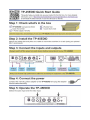
1
K R A ME R E LE CT R O N IC S L T D . USER MANUAL MODEL: TP-45EDID Component /UXGA /Audio Transmitter P/N: 2900-300126 Rev 2 Contents 1 Introduction 1 2 2.1 2.2 2.3 3 3.1 3.2 3.3 4 Getting Started Achieving the Best Performance Safety Instructions Recycling Kramer Products Overview Shielded Twisted Pair (STP)/Unshielded Twisted Pair (UTP) About the Power Connect™ Feature Defining EDID Defining the TP-45EDID Component/UXGA/Audio Transmitter 2 2 3 3 4 5 5 6 7 5 5.1 5.2 5.3 5.4 Connecting a Component/XGA – Audio Distribution System Connecting the System in XGA Mode Connecting the System in Component Video Mode Connecting the TP-45EDID Remote Control Wiring the CAT 5 LINE IN / LINE OUT RJ-45 Connectors 9 10 11 13 14 6 Acquiring the EDID 15 7 Technical Specifications 16 Figures Figure 1: TP-45EDID Component/UXGA/Audio Transmitter Figure 2: Component/XGA – Audio Distr bution System, XGA Mode Figure 3: Component/XGA – Audio Distr bution System, Component Video Mode Figure 4: The TP-45EDID Remote Control Connection Figure 5: CAT 5 PINOUT 7 11 13 14 14 TP-45EDID – Contents i 1 Introduction Welcome to Kramer Electronics! Since 1981, Kramer Electronics has been providing a world of unique, creative, and affordable solutions to the vast range of problems that confront the video, audio, presentation, and broadcasting professional on a daily basis. In recent years, we have redesigned and upgraded most of our line, making the best even better! Our 1,000-plus different models now appear in 11 groups that are clearly defined by function: GROUP 1: Distribution Amplifiers; GROUP 2: Switchers and Matrix Switchers; GROUP 3: Control Systems; GROUP 4: Format/Standards Converters; GROUP 5: Range Extenders and Repeaters; GROUP 6: Specialty AV Products; GROUP 7: Scan Converters and Scalers; GROUP 8: Cables and Connectors; GROUP 9: Room Connectivity; GROUP 10: Accessories and Rack Adapters and GROUP 11: Sierra Products. Congratulations on purchasing your Kramer TP-45EDID Component/UXGA/Audio Transmitter that uses existing UTP cabling to create an efficient, fast and uncluttered environment for: • Presentation and multimedia applications • Long-range graphics distribution for schools, hospitals, security, and stores • Security and military applications TP-45EDID - Introduction 1 2 Getting Started We recommend that you: • Unpack the equipment carefully and save the original box and packaging materials for possible future shipment • Review the contents of this user manual i 2.1 Go to http://www.kramerelectronics.com to check for up-to-date user manuals, application programs, and to check if firmware upgrades are available (where appropriate). Achieving the Best Performance To achieve the best performance: • Use only good quality connection cables (we recommend Kramer highperformance, high-resolution cables) to avoid interference, deterioration in signal quality due to poor matching, and elevated noise levels (often associated with low quality cables) • Do not secure the cables in tight bundles or roll the slack into tight coils • Avoid interference from neighboring electrical appliances that may adversely influence signal quality • Position your Kramer TP-45EDID away from moisture, excessive sunlight and dust ! 2 This equipment is to be used only inside a building. It may only be connected to other equipment that is installed inside a building. TP-45EDID - Getting Started 2.2 Safety Instructions ! 2.3 Caution: There are no operator serviceable parts inside the unit Warning: Use only the Kramer Electronics input power wall adapter that is provided with the unit Warning: Disconnect the power and unplug the unit from the wall before installing Recycling Kramer Products The Waste Electrical and Electronic Equipment (WEEE) Directive 2002/96/EC aims to reduce the amount of WEEE sent for disposal to landfill or incineration by requiring it to be collected and recycled. To comply with the WEEE Directive, Kramer Electronics has made arrangements with the European Advanced Recycling Network (EARN) and will cover any costs of treatment, recycling and recovery of waste Kramer Electronics branded equipment on arrival at the EARN facility. For details of Kramer’s recycling arrangements in your particular country go to our recycling pages at http://www.kramerelectronics.com/support/recycling/. TP-45EDID - Getting Started 3 3 Overview The TP−45EDID is a high−performance twisted pair transmitter for computer graphics or component video and unbalanced stereo audio signals. It converts the input signals to a twisted pair signal and transmits them over CAT 5 cable to a compat ble receiver. The TP-45EDID has two SELECT buttons that let you choose the video signal input (XGA or component) as well as the audio input (digital or analog signal). (The term XGA used throughout this manual implies resolutions exceeding UXGA.) By selecting the required video input signal, the TP-45EDID with the TP-46N can constitute either a component video (Y, CB/PB, CR/PR) or an XGA video – audio transmitter / receiver system: The TP-45EDID does not convert the video signal format. Thus computer graphics sources must be routed to computer graphics outputs. Similarly, component video sources must be routed to component video outputs. • If XGA is selected, the TP-45EDID receives an XGA and audio signal and transmits it over the CAT 5 cable to the XGA output on the TP-46N receiver • If component video is selected, the component video signal is transmitted over the CAT 5 cable to the COMP outputs on the TP-46N receiver • The analog audio or S/PDIF (digital audio)—as selected via the audio SELECT button—is transmitted together with the video signal over the CAT 5 cable to the TP-46N receiver • The TP-45EDID can execute these control functions also remotely using simple pushbuttons (see Section 5.3) The audio signal is distributed simultaneously to the analog or digital audio outputs. The TP-45EDID Component/XGA – Audio Transmitter features: • Transmission range of more than 300ft (more than 100m) • YUV input (also known as Y, Cb, Cr, or Y, B-Y, R-Y, or Y, Pb, Pr) on 3 RCA connectors and a computer graphics input on a 15-pin HD (F) connector • Digital audio input (S/PDIF) on an RCA connector and a stereo analog input on a 3.5mm mini jack 4 TP-45EDID - Overview • EDID capture that copies and stores the EDID from a display device • The Power Connect™ feature where one unit can power the other over the same CAT 5 cable • 12V DC power • Toggling push-button selector switches and status LEDs connected by a remote selector input terminal block 3.1 Shielded Twisted Pair (STP)/Unshielded Twisted Pair (UTP) We recommend that you use Shielded Twisted Pair (STP) cable, and stress that the compliance to electromagnetic interference was tested using STP cable. There are different levels of STP cable available, and we advise you to use the best quality STP cable that you can afford. Our non-skew-free cable, Kramer BC-STP is intended for analog signals where skewing is not an issue. In cases where there is skewing, our Unshielded Twisted Pair (UTP) skew-free cable, Kramer BC-XTP, may be advantageous, and UTP cable might also be preferable for long range applications. In any event when using UTP cable, it is advisable to ensure that the cable is installed far away from electric cables, motors and so on, which are prone to create electrical interference. 3.2 About the Power Connect™ Feature The Power Connect feature applies as long as the cable can carry power. This feature is available when using STP cable and the distance does not exceed 50m (164ft) on standard CAT 5 cable. For longer distances, heavy gauge cable should be used (TP cable is still suitable for the video/audio transmission, but not for feeding the power at these distances). For units which are connected via RJ-45 connectors, make sure that the shield of the STP cable is connected to the metal casing of the connectors on both ends of the cable. For units which are connected via terminal block connectors, the shield of the STP cable must be connected to a ground terminal on the units at both ends (use the ground terminal of the power supply connection if necessary). TP-45EDID - Overview 5 For a TP cable exceeding a distance of 50m, separate power supplies should be connected to the transmitter and to the receiver simultaneously. 3.3 Defining EDID The Extended Display Identification Data (EDID) is a data-structure provided by a display, to describe its capabilities to a graphics card (that is connected to the display’s source). The EDID enables the TP-45EDID to “know” what kind of monitor is connected to the output. The EDID includes the manufacturer’s name, the product type, the timing data supported by the display, the display size, luminance data and (for digital displays only) the pixel mapping data. EDID is defined by a standard published by the Video Electronics Standards Association (VESA). 6 TP-45EDID - Overview 4 Defining the TP-45EDID Component/UXGA/Audio Transmitter This section defines the TP-45EDID. Figure 1: TP-45EDID Component/UXGA/Audio Transmitter TP-45EDID - Defining the TP-45EDID Component/UXGA/Audio Transmitter 7 # Feature XGA IN 15-pin HD (F) Connector Connect to the XGA source 2 LINE OUT RJ-45 Connector Connect to the LINE IN connector of he receiver 3 EDID Status LED Illuminates during normal operation; flashes when acquiring the EDID 4 EDID CAPTURE Button Press to acquire the EDID information from the display 5 CONTROL AUDIO/VIDEO Terminal Block Connect to remote push-button switches and status LEDs 6 12V DC +12V DC connector for powering the unit 7 ANALOG AUDIO 3.5mm Mini Connector Connect to the stereo analog audio source 8 S/PDIF RCA Connector 9 AUDIO SELECT Button ANALOG AUDIO 10 ON LEDS UXGA 11 INPUTS 12 S/PDIF Connect to the digital audio source Press to toggle between analog audio and digital S/PDIF audio Lights when computer graphics video is selected ANALOG AUDIO Lights when analog audio is selected Y RCA Connector Connect to the component video source CB/PB RCA Connector 13 8 Function 1 CR/PR RCA Connector 14 VIDEO SELECT Input Button Press to toggle between component video and computer graphics video 15 ON LED Lights when receiving power TP-45EDID - Defining the TP-45EDID Component/UXGA/Audio Transmitter 5 Connecting a Component/XGA – Audio Distribution System The Component/XGA – Audio Distribution System can be configured to operate in one of two video modes: • In the XGA mode, a computer graphics source is connected to the input and transmitted to a display connected to the receiver (see Section 5.1) • In the component video mode, a component video source is connected to the input and transmitted to a TV set connected to the receiver (see Section 5.2) The Component/XGA – Audio Distribution System can be configured to operate in one of two audio modes: • In the analog mode, an analog audio source is connected to the input and transmitted to an acceptor connected to the receiver (see Section 5.1) • In the digital audio mode, an S/PDIF audio source is connected to the input and transmitted to a digital acceptor connected to the receiver (see Section 5.2) Thus, there are four possible system configurations: computer graphics/analog audio, computer graphics/digital audio, component video/analog audio, and component video/digital audio. The modes of the system are determined by setting the VIDEO SELECT and AUDIO SELECT switches on the TP-45EDID. Whatever modes are set at the transmitter the video and audio signals are sent to the receiver and any additional cascaded receivers. There is no signal conversion; a component input cannot be sent to a computer graphics output, nor can a digital audio input be sent to an analog audio output. TP-45EDID - Connecting a Component/XGA – Audio Distribution System 9 5.1 Connecting the System in XGA Mode To configure a TP-45EDID and TP-46N Component/XGA – Audio distribution system (using up to 300ft (100m) of UTP cabling) in the XGA mode, as illustrated in the example in Figure 2, do the following: 1. On the TP-45EDID, connect the following: An XGA source (for example, the graphics card on a laptop) to the XGA 15-pin HD (F) connector An analog audio source to the ANALOG AUDIO 3.5mm mini jack (or a digital audio source to the S/PDIF RCA connector), for example, using a Kramer C-GMA/GMA cable (VGA 15-pin HD (M) with audio jack to VGA 15-pin HD (M) with audio jack 2. On the TP-45EDID, use the SELECT buttons as follows: Momentarily press the video SELECT button. The UXGA LED lights when the UXGA input is selected Momentarily press the AUDIO SELECT button to toggle between the S/PDIF and analog audio inputs 3. On the TP-46N, connect the following: The XGA OUT 15-pin HD (F) connector to the XGA acceptor (for example, a display) The ANALOG AUDIO 3.5mm mini jack to the analog audio acceptor (for example, powered speakers) 4. Connect the LINE OUTPUT RJ-45 connector on the TP-45EDID to the LINE IN RJ-45 connector on the TP-46N, via CAT 5 cabling, see Figure 5. 5. Connect the 12V DC power adapter to the power socket and connect the adapter to the mains electricity on both the TP-45EDID and the TP-46N (not shown). The signal from the XGA source is transmitted via CAT 5 cable, decoded and converted at the XGA OUT 15-pin HD (F) connector to the XGA acceptor. 6. If required, connect the LINE OUT RJ-45 connector on the TP-46N to an additional TP-46N. 10 TP-45EDID - Connecting a Component/XGA – Audio Distribution System 7. On the TP-46N underside: Using a screwdriver to carefully rotate the trimmer, adjust the video output signal level and/or cable compensation equalization level, if required Figure 2: Component/XGA – Audio Distribution System, XGA Mode 5.2 Connecting the System in Component Video Mode To configure a TP-45EDID/TP-46N Component/XGA – Audio distribution system in the component video mode, as the example in Figure 3 illustrates, do the following: 1. On the TP-45EDID, connect the following: A component video source (for example, a DVD player) to the Y, Cb/Pb, Cr/Pr RCA connectors A digital audio source to the S/PDIF RCA connector using up to 300ft (100m) of UTP cabling TP-45EDID - Connecting a Component/XGA – Audio Distribution System 11 2. On the TP-45EDID, use the SELECT buttons as follows: Momentarily press the VIDEO SELECT button. The UXGA LED turns off when the component video input is selected Momentarily press the AUDIO SELECT button to toggle between the S/PDIF and analog audio inputs 3. On the TP-46N, connect the following: The Y, CB/PB, CR/PR RCA connectors to a component video acceptor (for example, a plasma display) The S/PDIF RCA connector to the digital audio acceptor (for example, the audio input on the plasma display) 4. Connect the LINE OUTPUT RJ-45 connector on the TP-45EDID to the LINE IN RJ-45 connector on the TP-46N, via CAT 5 cabling, see Figure 5. 5. Connect the 12V DC power adapter to the power socket and connect the adapter to the mains electricity on both theTP-45EDID and the TP-46N (not shown in Figure 3). The signal from the component video source is transmitted via the CAT 5 cable; decoded and converted to component video and outputted on the Y, CB/PB, CR/PR OUTPUTS RCA connectors to the component video acceptor. 6. Connect the LINE OUT RJ-45 connector on the TP-46N to a second TP-46N unit (optional). 7. If required, connect the LINE OUT RJ-45 connector on the TP-46N to additional TP-46N units. 12 TP-45EDID - Connecting a Component/XGA – Audio Distribution System Figure 3: Component/XGA – Audio Distribution System, Component Video Mode 5.3 Connecting the TP-45EDID Remote Control Connect momentary push-buttons and LEDs (each LED is driven by a 5V source and a 392Ω series resistor) to a cable and attach the cable to a 5-pin terminal block for connection to the TP-45EDID control port as shown in Figure 4. Each press of the selector button toggles the audio or video system mode and turns on or off the remote and panel status LEDs according to the active mode. TP-45EDID - Connecting a Component/XGA – Audio Distribution System 13 Figure 4: The TP-45EDID Remote Control Connection 5.4 Wiring the CAT 5 LINE IN / LINE OUT RJ-45 Connectors This section defines the CAT 5 pinout, using a straight pin-to-pin cable with RJ-45 connectors. i Note, that the cable Ground shielding must be connected / soldered to the connector shield. EIA /TIA 568B 14 PIN 1 Wire Color Orange / White 2 Orange 3 Green / White 4 Blue 5 Blue / White 6 Green 7 Brown / White 8 Brown Pair 1 4 and 5 Pair 2 1 and 2 Pair 3 3 and 6 Pair 4 7 and 8 Figure 5: CAT 5 PINOUT TP-45EDID - Connecting a Component/XGA – Audio Distribution System 6 Acquiring the EDID The transmitter can acquire the EDID information from the display connected to the transmitter or acquire the default EDID. To acquire the display EDID, do the following: 1. Connect the XGA INPUT 15-pin HD connector to the input XGA connector of the display, using a short cable. The EDID is carried over pins 12 and 15 of the VGA connector. It is essential that the cable used for capturing the EDID passes all 15 pins 2. Connect power to the display. 3. On the transmitter, connect the 12V DC power adapter to the power socket and connect the adapter to the mains electricity. 4. Press the EDID CAPTURE button. 5. Once the EDID STATUS LED flashes slowly several times, the EDID is captured. 6. Disconnect the display. To acquire the default EDID: Do not connect the display to he transmitter when acquiring the default EDID. 1. On the transmitter, connect the 12V DC power adapter to the power socket and connect the adapter to the mains electricity. 2. Press the EDID CAPTURE button. 3. Once the EDID STATUS flashes rapidly several times, the default EDID is captured. Alternatively, you can press the EDID CAPTURE button after connecting the transmitter receiver system. When the EDID STATUS LED flashes rapidly several times, the default EDID information is acquired. TP-45EDID - Acquiring the EDID 15 7 Technical Specifications INPUTS: Video: 1 component 1Vpp/75Ω (Y,Pb,Pr) on 3 RCA connectors, 1 XGA on a 15-pin HD connector; Audio: 1 unbalanced stereo audio, 0dBu/50kΩ, on a 3.5mm jack; 1 S/PDIF audio on an RCA connector OUTPUT: 1 CAT 5 on an RJ-45 connector (video/audio) MAX. INPUT LEVEL: XGA: 1.7Vpp on 75Ω, DC coupling; Y,Pb,Pr: 1.05Vpp on 75Ω, AC coupling RETURN LOSS: -18dB VIDEO RESOLUTION: Up to UXGA, 1080p *S/N RATIO: 69dB RMS @5MHz *K-FACTOR: 0.2% *ISOLATION (CROSSTALK): -43dB @ 5MHz *AUDIO BANDWIDTH: 20Hz to 20kHz *TND+NOISE: 0.33% @1kHz SAMPLE RATE CONVERSION: 48kHz RESOLUTION CONVERSION: 24 bits OPERATING TEMPERATURE: 0° to +40°C (32° to 104°F) STORAGE TEMPERATURE: -40° to +70°C (-40° to 158°F) HUMIDITY: 10% to 90%, RHL non-condensing POWER SOURCE: 12V DC, 920mA max. (TP-46N, TP-45EDID pair when powered from the TP-45EDID via power connect, CAT 5, 60m); TP-45EDID self current:110mA D MENSIONS: 12cm x 7.15cm x 2.76cm (4.7" x 2.81" 1.09") W, D, H WEIGHT: 0.3 kg (0.67 lbs) approx ACCESSORIES: Power supply Specifications are subject to change without notice at http://www.kramerelectronics.com * Starred specifications are measured using a TP-45EDID and TP-46N pair unless o herwise stated. 16 TP-45EDID - Technical Specifications For the latest information on our products and a list of Kramer distributors, visit our Web site where updates to this user manual may be found. We welcome your questions, comments, and feedback. Web site: www.kramerelectronics.com E-mail: [email protected] ! P/N: SAFETY WARNING Disconnect the unit from the power supply before opening and servicing 2900- 300126 Rev: 2