1
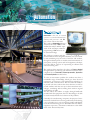
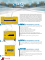
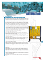
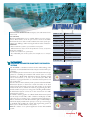
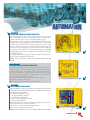
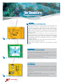
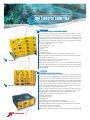
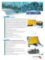
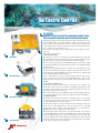
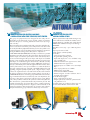
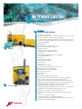
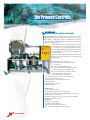
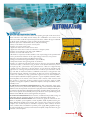
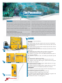
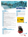
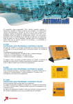
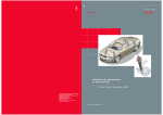
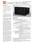
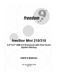
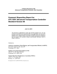
the PLC
the Interactive Training Systems
the Electric Controls
the Simulators
the Process Controls
the Pneumatics and the Hydraulics
Table of Contents
PAGE
CODE
DESCRIPTION
page 4
DL 2110B
Programmable Logic Controller - 38 IN/34 OUT
page 4
DL 2110A
Programmable Logic Controller - 24 IN/16 OUT
page 4
DL 2110AH
Programmable Logic Controller - 12 IN/8 OUT
page 5
DL 2110-131K
Programmable Logic Controllers Modular Trainer
THE PLC
THE INTERACTIVE TRAINING SYSTEM
page 6
DL 2110ITS
Interactive PLC Trainer for Industrial Processes
page 7
DL 2110RTIS
Simulation Software for Road Traffic Information Sistem
THE SIMULATORS
page 8
DL 2112
Analogue Input/Output Simulator
page 8
DL 2112RM
Analogue Input/Output Simulator
page 8
DL 2113
Digital Input Simulator
page 8
DL 2113RM
Digital Input/Output Simulator
page 9
DL 2120
Two-Floor Parking Garage Simulator
page 9
DL 2120RM
Two-Zone Parking Garage Simulator
page 9
DL 2124
Belt Conveyor Simulator
page 10
DL 2121
Smart Traffic Lights Simulator
page 10
DL 2121RM
Smart Traffic Lights Simulator
page 10
DL 2122RM
Lift Simulator
page 11
DL 2122M
Lift Model
page 11
DL 2122
Lift Simulator
THE ELECTRIC CONTROLS
page 12
DL 2104G
Electromechanic Component Board
page 12
DL 2123
Squirrel Cage Motor Control
page 13
DL 2125
DC Motor Speed Control
page 13
DL 2126B
Didactic System for Servo-Motor Control Study
page 14
DL 2127B
Didactic System for Electric Machines Control Study with Frequency
Inverter and Electrodynamic Brake
page 15
DL 2128B
Didactic System for Electric Machine Control Study with Static
Start Key/Soft Starter
page 15
DL 2129B
Didactic System for Step Motor Control Study
THE PROCESS CONTROLS
page 16
DL 2314
Process Control Trainer
page 17
DL 2314S
Process Measurement and Control System
page 18
DL 2314BR
Didactic Process Control Pilot Plant
page 19
DL 2312HG
Sensor and Transducers Trainer
THE PNEUMATICS AND THE HYDRAULICS
page 20
DL 8110P
Pneumatics
page 21
DL 8115EP
Electro-Pneumatics
page 21
DL 8110SLZ
Air Compressor
page 21
DL 2110ATN
Programmable Logic Controller - 24 IN/16 OUT
page 24
DL 8161
Pneumatic Trainer
page 24
DL 8171
Electro-Pneumatic Trainer
page 25
DL 8110H
Hydraulics
Automation
INTRODUCTION
Automation is the use of control
ol
asystems to control industrial maCss
chinery and processes and PLCs
play a main role in this field.
This is why our Automation laboratory
ryy
starts from the study of PLCs, to allow
ow
w
students the analysis and the acqui-sition of the techniques related too
programming a PLC and to its use
in control technology.
The catalogue continues with the presentation
i off all
ll the
h applications that we have designed to facilitate, in a user-friendly and stimulating way, the work of teachers and students,
through simulation panels or models, virtual environments or
pilot plants, teaching systems with real equipment, all adapted to the didactic purpose of representing an efficient and
effective learning tool.
The catalogue then introduces the subject of Process Control
through trainers reproducing real industrial situations and is
completed by our Pneumatics, Electro-pneumatics, Hydraulics
and Electro-hydraulics work benches.
To solve an automation problem, the student must have a
remarkable range of knowledge, which goes from electrical
engineering to electronics, from information technology to
mechanics and communications. The aim of this laboratory is
to provide tools that combine the above domains, in order to
provide students with the most up-to-date automation technologies, stimulating and fascinating them with an original
methodology of study.
For this reason, the student is taught, through handbooks
provided with the equipment, the basic knowledge to be able
to autonomously find the best solution of the problems.
Currently, for manufacturing companies, the purpose of automation has shifted from increasing productivity and reducing
costs, to broader issues, such as increasing quality and flexibility in the manufacturing process. We believe that our didactic
equipment represent a substantial contribution to the fulfilment of the aforesaid objectives.
the PLC
The programmable logic controller (PLC) allows controlling machines and installations by using the sequential logic that replaces the traditional electromechanical boards, allowing, therefore, to save relays, timers and counters.
Moreover, the main advantages in the use of the PLC are the flexibility, because they can be re-programmed, the industrial characteristics, thanks to
the possibility of their use in environments with heavy working conditions,
the reliability and the safety, typical of the solid state technology that has no
moving contacts, as well as the possibility to process analogue signals.
DL 2110B
DL 2110B
PROGRAMMABLE LOGIC CONTROLLER – 38 IN/34 OUT
The DL 2110B unit is a programmable controller that combines high
performances and ease of use for those who are approaching for the
first time the world of PLC.
The proposed configuration includes:
• CPU with 24 digital inputs and 16 relay outputs
• module with 8 digital inputs and 8 relay outputs
• module with 8 digital outputs (transistor)
• 2 modules with 3 analogue inputs and 1 analogue output each
The unit is fitted in an accessible container while on the panel the input/output terminals are shown, suitably duplicated by means of connectors.
The DL 2110B is complete with the programming software.
DL 2110A
DL 2110A
211
11
10A
0A
PROGRAMMABLE LOGIC CONTROLLER – 24 IN/16 OUT
This unit has technical and functional characteristics similar to the
ones of the DL 2110B, but it is composed of the CPU only with 24
digital inputs and 16 relay outputs. Complete with the programming
software.
DL 2110AH
PROGRAMMABLE LOGIC CONTROLLER – 12 IN/8 OUT
DL 2110AH
0A
AH
4 De Lorenzo Group
Easy to be programmed from its own panel, without computer.
It is composed (including the extension module) of 12 digital inputs
and 8 relay outputs.
Simulation of the inputs through switches and externally through
terminals.
The programming software is also supplied to allow programming the
PLC from the computer, if so preferred.
DL 2110-131K
PROGRAMMABLE LOGIC CONTROLLERS MODULAR TRAINER
This modular trainer allows the study of PLC and/or MMI. The modular panel
is a tubular steel structure, treated with electrostatic painting, dimensions: w= 660
mm, h=935 mm, d=350mm. It has 4 lines for manual and fast fixation of the modules without the need for tools. Each module is made of steel plate, treated with
electrostatic painting. All terminals and connection points are available through
2 or 4 mm terminals (according to the voltage). The dimensions of the modules
are 200 x 110 mm. or multiples. The components, as well as their terminals and
access points, are identified with the respective symbol printed in silk-screen.
• PLC module: a Programmable Logic Controller with integrated Man-MaMa
ing
chine Interface (MMI) and liquid crystal display. It includes the programming
ital
software. Configuration: 8 transistor digital inputs (24 Vdc), 6 transistor digital
dc),
outputs (24 Vdc), 4 analogue inputs (0-10 Vdc), 1 analogue output (0-10 Vdc),
1 pulse fast counting input (4 kHz). All of the inputs and outputs are accessible
ble
through 2 mm terminals and identified with symbol in silk-screen.
• Input power module, with protection switch and lights.
Power supply: single-phase from mains.
• Power supply module with polarity inversion and over-current protection.
Outputs: 12 Vdc, 24 Vdc and 0 ÷ 24 Vdc.
• Module with switches for digital input signals simulation. It includes 8 fixed
contact switches with retention, NC/NO, for simulating the logic levels.
tact
• Module with switches for digital input signals simulation. It includes 8 contact
pulse switches, NC/NO.
• Module with switches for digital input signals simulation. It includes 4 contact
tact
pulse switches, NC/NO and 4 contact retention switches, NC/NO.
• Module with 8 led for light indication of output digital signals, suitable for
PLC with NPN or PNP outputs.
• Module with 2 linear potentiometers for simulation of voltage or current signals (4 to 20 mA and 0 to 12 Vdc).
• Module for analogue signals measurement. Possibility to measure 2 signals simultaneously. One of the inputs is suitable for current signals from 4 to 20 mA
and the other for voltage signals from 0 to 10 Vdc.
• Module with step motor, with 4 bits electronic driver, with light indication for
each bit.
• Module with 4 relays for 10 A and 24 Vdc coil, suitable for PLC with NPN or
PNP outputs.
• Module with DC motor and encoder, suitable for PLC with NPN or PNP inputs.
• Module with Analogue/Digital converter. 4 bits A/D converter, with analogue
signals input from 0 to 5 Vdc / 0 to 24 Vdc and output from 4 to 20 mA and 4
bits in 24 Vdc.
• Module for Digital/Analogue converter. 4 bits D/A converter, with maximum
analogue output signals adjustable from 5 to 24 Vdc and from 4 to 20 mA and
4 bits from 5 to 24 Vdc input.
Supplied with a set of 30 connection cables, 2 and 4 mm, and an experiment
manual.
DL 2110-13
2110-131K
21102110
21
13
31
1K
K
De Lorenzo Group
5
the Interactive Training
Systems
DL 2110ITS
INTERACTIVE PLC TRAINER FOR INDUSTRIAL PROCESSES
The DL 2110ITS is a training tool for PLC programming, that uses a
PLC SIEMENS (SIMATIC S7-200 or S7-300 series) and an interactive educational software for the simulation of industrial environments
to be controlled.
HOW DOES IT WORK?
DL 2110ITS-200
The DL 2110ITS offers five virtual industrial processes to learn how to
program a PLC, with real situations of sorting, batching, palletizing, pick
and place and automatic warehousing. Each process reproduces the visual
simulation of an industrial situation, including virtual sensors and actuators, so that the state of the system is “sensed” and controlled by the PLC:
The objective is to program the PLC to control each of the five virtual
processes as if they were real systems.
The information is exchanged between the PLC and the virtual system
through a data acquisition board (DAQ) provided with 32 I/O isolated
channels and USB interface.
MAIN FEATURES
• PLC Siemens of the SIMATIC S7-200 or S7-300 series
• 3D realistic graphics
• Real-time physics that closely emulates what happens in real life
• 3D real-time sound
• Total interactivity with the systems
• Friendly user interface
• Easy and fast to setup
Based on the latest PC technology, the DL 2110ITS makes PLC training easy and fun. Virtual environments have never been so real, featuring cutting-edge 3D real-time graphics, sound and total interactivity.
The result is an immersive simulated environment that allows highly realistic training processes, without any risk of injury to man or damage to
machines. The automation tasks are presented with increasing levels of
difficulty, so that users can progress to more advanced exercises as they
improve their skill.
REAL WORLD BASED TRAINING SYSTEM
DL 2110ITS-300
The DL 2110ITS presents five training processes based on real world
industrial scenarios. Each process offers standard problems found in
PLC programming, presented in order of increasing level of difficulty.
DESCRIPTION OF THE PROCESSES
SORTING: transport cases from the entry bay to the elevators, sorting
them by height
BATCHING: mix three primary colors (red, green and blue) in order
to obtain a desired color
PALLETIZER: palletize cases up to three layers
PICK & PLACE: place parts inside boxes through a three axes manipulator
6
De Lorenzo Group
AUTOMATIC WAREHOUSE: transport, store and retrieve boxes
from a rack
FAULT SIMULATION
The DL 2110ITS allows you to simulate failures in sensors and actuators. These failures can be in open circuit or short-circuit. With
this feature the user is able to induce malfunctions in the system, presenting new challenges and increasing the realism of the simulation.
INTERACTIVITY
• Interact with the system as you would in a real system
• Add and remove objects from the production circuit, at any time
during the simulation
• Cause error situations or system jams
• Test individual parts of the system; for example: test a conveyor
table
DL 2110RTIS
SIMATIC S7-200
CPU 226
AC/DC/Relay
24 digital inputs
16 digital outputs
PC/PPI USB
programming cable
STEP 7 MicroWIN
DE LORENZO code:
DL 2110ITS-200
SIMATIC S7-300
CPU 312C
Additional module SM 323
18 digital inputs
14 digital outputs
Power supply
PS 307 24VDC/2A
Micro Memory Card 64kByte
USB PC-adapter
for the connection PC/PLC
480 mm. guide
STEP 7 Lite
Simulation area with
micro-switches and terminals
DE LORENZO code:
DL 2110ITS-300
SIMULATION SOFTWARE FOR ROAD TRAFFIC INFORMATION
SYSTEMS
DL 2110RTIS is a simulation software for the understanding of the
operations of a Road Traffic Information System and for PLC programming.
A simulated operations environment can be interfaced with real equipment for controlling the simulation. The virtual system is a visual
simulation of a Road Traffic Information System, including virtual
sensors and actuators, so its state can be sensed by the PLC. The
objective is to program the PLC to control the virtual system as if it
was a real system.
For those that are interested only in the operation of the Road Traffic
Information System, to learn how it works and what can be done
with it from the functional point of view, this product can be used in
manual mode, that is, without the need for programming the PLC,
and the student can practice in using and controlling the Road Traffic Information System as if he was in the control room of a traffic
management company.
It includes: realistic graphics of a Road Traffic Information System
for the study of road traffic, traffic conditions and display of traffic
safety messages on warning signs, a simulated graphical display module, to memorize more than 10 road traffic signs, a simulated alphanumerical display module with capacity to store up to 20 messages,
a simulated radar module, the control and programming system. It
allows you to simulate failures in the system.
NOTE: this software is an optional application for the DL 2110ITS
system.
De Lorenzo Group
7
the Simulators
DL 2112
ANALOGUE INPUT/OUTPUT SIMULATOR
The simulator is essential and indispensable for operation and understanding of the analogue modules of the PLC. The board includes 2+2
inputs, at 4-20 mA and 0-10 V respectively, and 4 outputs at 4-20
mA/0/1-5 V, smoothly variable through potentiometer; the current/
voltage display is of digital type; the input indication is of bar type,
through meters that can be switched. Moreover, 4 outputs at 24 Vdc/1
A are available, internally powered. The connection to the PLC can be
carried out through terminals or connector.
Power supply: single-phase from mains.
Complete with connecting cables, educational manual and software.
NOTE: It can be connected to a PLC such as the DL 2110B.
DL 2112
DL 2112RM
ANALOGUE INPUT/OUTPUT SIMULATOR
DL 2112RM
It includes 1+1 inputs, at 4-20 mA and 0-10 V respectively, and 1+1 outputs
at 4-20 mA/0-5 V, smoothly variable through potentiometer; the current/voltage
display is of digital type.
The connection to the PLC can be carried out through terminals.
Power supply: single-phase from mains.
Complete with connecting cables, educational manual and software.
NOTE: It can be connected to a PLC such as the DL 2110B.
DL 2113
DIGITAL INPUT SIMULATOR
DL 2113 (on the left, PLC not included)
The simulator allows studying and analyzing the programming techniques through automatisms which are freely and imaginatively implemented. Moreover, it allows the PLC potentialities to be pointed out.
The board includes 32 switches on 4 columns for PLC input enabling, with
a LED signalling the on/off state of the individual switch and the possibility
of marking the references on special tags that can be cancelled; moreover, 4
outputs at 24 Vdc/1 A are available, internally powered. The connection to
the PLC can be carried out through terminals or connector.
Power supply: single-phase from mains.
Complete with connecting cables, educational manual and software.
NOTE: It can be connected to a PLC such as the DL 2110A or DL 2110B.
DL 2113RM
DIGITAL INPUT/OUTPUT SIMULATOR
DL 2113RM
8
De Lorenzo Group
It includes 8 switches for PLC input and 8 LED for PLC output.
The connection to the PLC can be carried out through terminals.
Power supply: single-phase from mains.
Complete with connecting cables, educational manual and software.
NOTE: It can be connected to a PLC such as the DL 2110AH.
DL 2120
TWO-FLOOR PARKING GARAGE SIMULATOR
The system represents a two-storey parking garage where it is possible to realistically simulate all the sequences that a car driver has to
perform when he wants to use an automated parking garage.
The automatic control is performed through a PLC, whose program
manages the displays signalling vacant and full places, both at the
entrance and at every floor, the opening and closing of the in and out
barriers, the lighting intensity at each floor, regulated by the presence
of at least one car detected by special sensors, and the smoke and
fire detectors. The number of cars in the parking garage is displayed
through LED, whose control is assigned to an electronic circuit separated from the PLC.
Complete with connecting cables, educational manual and software.
Power supply: single-phase from mains.
NOTE: It can be connected to a PLC such as the DL 2110A or the DL
2110B.
DL 2
2120
120
12
0
DL 2120RM
TWO-ZONE PARKING GARAGE SIMULATOR
It represents a two-zone parking garage where it is possible to realistically simulate the sequences that a car driver has to perform when he wants to use an
automated parking garage. The automatic control is performed through a PLC,
whose program manages the displays signalling vacant and full places for both
zones and the opening and closing of the in and out barriers. The number of cars
in the parking garage is displayed through LED.
Complete with connecting cables, educational manual and software.
Power supply: single-phase from mains.
NOTE: It can be connected to a PLC such as the DL 2110AH.
DL 2120RM
212
120
0
DL 2124
BELT CONVEYOR SIMULATOR
The board allows simulating the transfer of material. The system of rolls
used for the transport, the loading and the accumulation of material are
simulated by means of LED.
Test signals are available, such as:
• wrong programming indicator
• limit switch closing indicator
• optical-acoustic indicator for alarms
• motor overload indicator
Besides the automatic control carried out through the PLC, it is possible to manually carry out all the operations.
The system is complete with educational manual.
Power supply: single-phase from mains.
NOTE: It can be connected to a PLC such as the DL 2110A or the DL 2110B.
DL 2124
De Lorenzo Group
9
the Simulators
DL 2121
SMART TRAFFIC LIGHTS SIMULATOR
This system represents a crossing between two one-way streets, each
controlled by a semaphore and provided with three pedestrian crossings with semaphores, too. The automatic control of the semaphore
system is performed through PLC not with the normal cyclic timing:
only the presence of at least one car determines the green signal of the
relevant semaphore, allowing the transit of all the cars between the two
detecting sensors.
The dialogue between the semaphores of the two roads allows the alternation of the green signal as a function of the traffic intensity, while
the pedestrian crossing is on request. The present cars are displayed
through LED, whose control is assigned to an electronic circuit separated from the PLC.
Complete with connecting cables, educational manual and software.
Power supply: single-phase from mains.
NOTE: It can be connected to a PLC such as the DL 2110A or the DL
2110B.
DL 2
2121
121
12
21
DL 2121RM
SMART TRAFFIC LIGHTS SIMULATOR
DLL 2
2121RM
212
121
1
21R
1RM
1RM
It represents a crossing between two streets, each controlled by a semaphore,
with a pedestrian crossing, also controlled by a semaphore.
The automatic control of the semaphore system is performed through PLC, as
a function of the arrival of the cars or of the call by a pedestrian. All the above
situations are simulated through pushbuttons.
NOTE: It can be connected to a PLC such as the DL 2110AH.
DL 2122RM
LIFT SIMULATOR
DL 2122RM
10
De Lorenzo Group
It simulates a three-stop lift with real processing procedures. Lift car up-down
manual cycle with automatic PLC control and management. The lift car motion
is displayed by LED. Booking obtained through buttons, on priority basis and
independently from the lift car position. Lift car door open indication. Upper
and lower limit switches to avoid programming mistakes. Connection to PLC
through terminals.
Power supply: single-phase from mains.
Complete with connecting cables, educational manual and control software.
NOTE: It can be connected to a PLC such as the DL 2110AH.
DL 2122M
LIFT MODEL
The model consists of a real three-stop scaled down lift and allows an
innovative approach to PLC control and management.
The model includes:
• lift car up-down and position visual signalling at each floor
• photocell on the lift car door to stop its closing in presence of an obstacle
• booking to be effected through buttons with flashing signalling, on
priority basis and independently from the lift car position
• lift car geared motor, hoist and electromagnetic brake
• floor, safety and lift car deceleration limit switches
• lift car and floor door open-shut motors
• motor protection thermal relays simulated by buttons
• lift car deceleration, either up and down, near the stop floor
• reproduction of the inside lift car switch panel
• installation graph on the panel
• connection to PLC through terminals or connectors
• fault simulator through micro-switches
Power supply: single-phase from mains.
Complete with connecting cables, educational manual and control software.
NOTE: It can be connected to a PLC such as the DL 2110B, although it is
possible to use also a DL 2110A, but without booking visual signalling
on the lift car switch panel.
DL 2122M
DL 2122
LIFT SIMULATOR
The simulation board is a three-stop lift with real processing procedures.
Lift car up-down manual cycle with automatic PLC control and management. The lift car motion is displayed by LED bar-graph while the
floor and safety limit switches are displayed by LED.
Booking to be effected through buttons with flash signalling, on priority
basis and independently from the lift car position.
Lift car and floor door open-shut button simulators. Motor thermal
relay button simulator. LED signalling for the activation of the electromagnetic brake of the lift car motor and for floor door opening.
Reproduction of the inside lift car switch panel: booking by lighting
buttons, STOP and ALARM buttons. At each floor and on the lift car
panel the lift car position and the up-down indication are displayed
by LED.
Fault simulator by micro-switches. Connection to PLC through terminals or connectors. Power supply: single-phase from mains. Complete
with connecting cables, educational manual and control software.
NOTE: It can be connected to a PLC such as the DL 2110A or the DL
2110B.
212
122
DL 2122
De Lorenzo Group
11
the
Electric
Controls
the Electric Controls
DL 2104G
ELECTROMECHANIC COMPONENT BOARD
The board allows performing the most important experiments in industrial electrical plants. The components are connected to the board front
panel through 2 mm terminals for what concerns the low voltage controls
and through 4 mm safety terminals for the connections to the mains. All
the components are identified through a clear synoptic diagram showing
their type and symbol. The board includes:
• 1 power supply, 24 V
• 1 bipolar switch, 1 - 0 - 2
• 1 thermal relay
• 2 timers
• 5 push-buttons
• 5 signalling lamps
• 5 remotely controlled switches with relevant auxiliary contacts
On the back side of the board there are switches to allow for the introduction of faults by the teacher.
The board is complete with a kit of connecting leads.
Power supply: single-phase from mains.
NOTE: It can be connected to a PLC such as the DL 2110A or DL 2110B.
Accessories: the electromechanical component board can be used together
with a Dahlander motor, such as DL 2102D, or a squirrel cage motor, such
as DL 10115AV.
DLL 2104G
G
DL 2123
SQUIRREL CAGE MOTOR CONTROL
The board, allowing the simulation of starting systems for the motors with
squirrel cage rotor, is equipped with a clear synoptic diagram that shows
through terminals: the push-buttons, the thermal relay contacts, the contactor coils and the signalling lamps. The system, besides the board, includes
a three-phase asynchronous motor supplied at the reduced voltage of 42 V,
complete with educational base and terminals that make easy the connection to the simulation panel. The speed meter, connected to an opto-encoder,
allows measuring the rotation speed of the motor.
Besides, a magneto-thermal switch and an emergency key allow the immediate interruption of the supply circuit in case of overload or short-circuit.
With this system, the student will be able to study the following:
• Telestarting of three-phase asynchronous motor
• Running teleinversion
• Star-delta telestarting
• Bias teleswitch
• Star-delta telestarting with running teleinversion
• Bias teleswitch for two speed motor of Dahlander connection.
The checking and the automatic management are carried out by means of PLC.
Complete with educational manual.
Power supply: single-phase from mains.
NOTE: It can be connected to a PLC such as the DL 2110A or the DL 2110B.
DL 2123
12
De Lorenzo
rennzzoo GGr
Group
roup
rro
ooup
uup
DL 2125
DC MOTOR SPEED CONTROL
The system has been designed for the study of programmable logic control
techniques in the control of the speed of a separately excited dc motor. The
speed regulation includes two control loops: hardware current loop with overcurrent limiting and speed loop with external PLC control. Speed measuring
with a tachogenerator or with an opto-encoder via frequency/voltage converter. Speed reference set by means of potentiometer or selector switches and
under PLC control. The PI controller modulates the PWM circuit that drives
the power stage consisting of switching transistor. Possibility of acceleration
and deceleration ramps programming. Pointer meters for motor speed, voltage
and armature current; connection to PLC through terminals or connectors.
The system is supplied with a machine set consisting of a dc permanent magnet motor, a dc tachogenerator, an encoder and a manual shoe brake.
Power: 48 Vdc, 5 A.
Tachometric signal: 180 V at 3000 rpm.
Power supply: single-phase from mains.
Complete with connecting cables, teacher’s manual and student’s work forms.
With this system, the student will be able to study the following:
• Open loop speed control
• Closed loop speed control
• Use of the PLC for the speed measuring
• Acceleration and deceleration ramps programming
• Duty cycle monitoring
NOTE: It can be connected to a PLC such as the DL 2110B.
DL 2125
DL 2126B
DIDACTIC SYSTEM FOR SERVO-MOTOR CONTROL STUDY
Didactic system for the study and training of servo-motors and controllers..
It includes a transistorized digital servo-converter with control through
h
PWM vector modulation, for brushless alternating current servo-motorss
driving in four quadrants. Specifications:
Servomotor: 2.5N/m, 2000 rpm
Nominal current: from 7 to 9 A
Dynamic current: from 15 to 17 A
Graduated inertia disk.
Transistorized digital servo-converter with PWM vector control
2 stop functions for positioning
Programmable encoder simulation: from 1 to 2048 pulses/rotation
Programming through PC or built-in MMI (man machine interface)
Serial communication: RS232
Input power: three-phase
Complete with a set of cables for all necessary connections and servomotor connection cable with RS 232 interface.
DL 2126B
D
SERVO
DL 2126B SE
ER
De Lo
De
Lor
LLorenzo
oor
oren
ore
orenzo
ren
eennzo
zo GGroup
roupp
ro
13
13
the
the Electric
Electric Controls
Controls
DL 2127B
DIDACTIC SYSTEM FOR ELECTRIC MACHINES CONTROL STUDY
WITH FREQUENCY INVERTER AND ELECTRODYNAMIC BRAKE
DL 2127B
DL 2127B - ME
METER
ETER
R
7B
B - MO
OTOR
R
DL 2127B
MOTOR
AKE
DL 2127B - BRAKE
14
De Lorenzo Gro
Group
roup
rooup
up
This training system has been designed for the study of the theoretical concepts and the solution of problems related to the process of speed control
of AC machines. Focusing on the electronic control of these machines, the
system allows the use and the study of the components and of the electronic circuits that are used in this process.
They are the same devices that are used by the industry, adapted for laboratory use.
The system is composed of:
• FREQUENCY INVERTER PANEL
The frequency inverter is mounted on a painted aluminium panel, that
shows the silk-screen electric diagram, the inputs and the outputs as well as
the representation of the inverter internal circuits blocks diagram.
The power inputs and outputs are available through 4 mm terminals, while
the digital and analogue signals inputs and outputs are available through
2 mm terminals.
All inverter parameterization, like acceleration and deceleration ramp,
maximum and minimum frequency, besides several other parameters, are
made through a built-in MMI (man machine interface) or, alternatively,
from a PC through the RS-485 interface.
Inverter characteristics: micro processed frequency inverter with singlephase or three-phase input power, sinusoidal PWM type, with no-controlled rectifiers at the input, capacitive filter and transistorized inverter
(IGBT).
• THREE-PHASE ASYNCHRONOUS MOTOR
Mounted on a metal base with elastic connection to be coupled to the
brake device. The connection terminals are available through the 4 mm
terminals on the panel that shows the printed representation of the coils
and outlines the possible connections.
Motor characteristics: power 0.5 HP, three-phase, 4 poles, 1720 rpm. Nominal torque 3.17 Nm, starting torque 250% and rotor inertia 0.0029 Kgm²
• ELECTRODYNAMICS BRAKE
Mounted on the same motor metal base, the brake device is composed of
an oscillating arm where two coils and an aluminium disk are assembled,
forming a Foucault currents brake system.
It allows the simulation of loads for the motor axis, making possible also
to block its axis. The applied force to the axis of the motor is controlled
through DC tension and this same mechanical force is measured by a
digital dynamometry coupled to the brake system.
Electromagnetic brake characteristics: type: Foucault disk, coils voltage 0
to 190 Vac adjustable by potentiometer, braking force 7.0 Nm, force sensor:
load cell, digital torque meter, connection through 4 mm. terminals. The
system is complete with technical manuals of all equipments with technical
information for operation and configuration / parameterization and with a
set of cables for all necessary connections.
DL 2128B
DL 2129B
DIDACTIC SYSTEM FOR ELECTRIC MACHINES
CONTROL STUDY WITH STATIC START KEY/SOFT-STARTER
DIDACTIC SYSTEM FOR STEP
MOTOR CONTROL STUDY
This group of equipment has been designed for the study, the understanding of the theoretical concepts and the solution of problems
related to the process of starting alternated current motors by using a
static start key.
The system allows the use and the study of the components and of the electronic circuits that are used in this process. They are the same devices that
are used by the industry, adapted for laboratory use. It is also possible to use
conventional motors start circuits (direct and star/ triangle) for comparisons
among the different starting systems. The system is composed of:
• STATIC START KEY PANEL (SOFT-STARTER). The Start Key is mounted on a painted
aluminium panel, that shows the silk-screen electric diagram, the inputs
and the outputs as well as the representation of the static start key internal circuits blocks diagram. The power inputs and outputs are available
through 4 mm terminals, while the digital and analogue signals inputs
and outputs are available through 2 mm terminals. All static start key
parameterization are made through a built-in MMI (man machine interface) or, alternatively, from a PC through the RS-485 interface. Static
start key characteristics: micro processed device to control the thyristors
shot angle, external start/stop command or by MMI, fault detection and
signalling, 4 digital optically-coupled inputs, 3 digital outputs, output
contacts for sequential motors start and for DC break, rated current 16
A, running current 115%, three-phase operating voltage, category AC 3.
• CENTRIFUGAL FAN. Made of a motor/fan group with the function of simulating an inertial load for the motor driven by static start key. Motor characteristics: three-phase asynchronous induction motor, power 4HP, 2
poles, 3425 rpm, B14, continuous S1 operation, isolation class (B) 130C.
Fan characteristics: painted aluminium body, maximum pressure 190
mmCA, maximum flow: 54 m3/min. The system is complete with static
start key and centrifugal fan electric diagrams, technical manuals of all
equipment with the technical information for operation and configuration/parameterization, group of cables for all necessary connections.
DL 2128B - load
Didactic system for the study and the training on step
motors and relevant controllers. It includes a transistorized digital step controller with control through
PWM vector modulation for step motor driving.
SPECIFICATIONS:
Step Motor: micro step - up to 51200 steps/revolution
• Input power: 24 to 75 Vdc
• Static Torque: 2.14 Nm (75Vdc)
Controller:
• Close and open loop operation
• Programmable operating current
• Inputs and outputs: 16 / +5 to +24 VDC / relay
type / normally open
• OFF-ON transition time: approx. 10 ms / ONOFF transition time: approx. 8 ms
• Analogue input: 0 to 5 VDC or 4 to 20 mA (10
Bit)
• Select output pulse rate: 0 to 5 MHz
• PWM output: up to 1 kHz
• Communication: RS485 or RS232
• Internal magnetic encoder: resolution 512 lines/2048 steps/revolution
Controller Power supply:
• Input: single-phase from mains
• Output: open 70 V, continuous operation 68 V /
3 A, peak 64 V / 6 A
Complete with a set of cables for all necessary connections and an RS 232 communication cable.
DL 2128B
DL 2129B
De Lorenzo Group
15
the
Process
Controls
the Electric Controls
DL 2314
PROCESS CONTROL TRAINER
The trainer is composed of:
• an educational board with a pressurized vessel and a set of sensors and
actuators for level, pressure, temperature and flow;
• a control module, containing the interface circuits for the sensors and
the actuators and the ON/OFF, proportional, integral and derivative
control circuits (PID).
TECHNICAL FEATURES
DL 23
2314
314
D
ETAIL
IL
DL 2314 - DETA
DETAIL
Pressurized vessel capacity: 5 litres approx.
Water tank capacity: 20 litres approx.
Temperature sensors:
• platinum thermo-resistance Pt 100
• bi-metallic direct reading thermometer
Level sensors:
• linear variable-differential transformer (LVDT)
• on-reed ON/OFF sensor
Flux sensors:
• flowmeter 8000 pulses/litre
• flowmeter, direct reading
Pressure sensors:
• strain gauge
• manometer, direct reading
Recirculation pump: 6 litres/minute, 12 V, 1.5 A
Motor driven valve: 4 manual valves
Water heating resistance: 48V, 200W
Safety valve set at 2.4 bar
Safety thermostat
Piping: brass
Power supply: single-phase from mains
With this system, the student will be able to study the following:
• Study of the level, flow, pressure and temperature sensors
• Study of the characteristics of the pump and of the motor pump
• Study of the characteristics of the static process and of the time constants
• ON-OFF, P, PI, PD and PID closed loop control of the level
• P, PI, PD and PID closed loop control of the flow
• ON-OFF, P, PI, PD and PID closed loop control of the temperature
• ON-OFF control of the level with the pressure sensor
Optionally, it is possible to connect to the trainer:
• a microprocessor based process controller of industrial type (DL
2314C)
• a process recorder (DL 2314R)
• a programmable logic controller (DL 2110B)
• a personal computer with suitable interface module and software (PC
with DL 1893 and DL 2314SW)
16
De Lorenzo Group
Grooouup
up
DL 2314S
PROCESS MEASUREMENT AND CONTROL SYSTEM
The system has the purpose of training students on measurement
and control of industrial quantities.
It is composed of 5 separate trainers, each dealing with a specific industrial parameter, namely pressure, temperature, flow rate,
level and pH, allowing users the study of standard industrial
transmitters, controllers and relevant diagrams that are used in
control engineering.
The system allows comparing among measurement devices operating on different physical principles, evaluating different types
of electronic transducers, studying the different parameters of a
control system.
A regulation and control module
dule is available for those who wish to experience
xperience P,
PD, PI and PID process controls,
trols, in addition to the standard ON/OFF
FF control.
Furthermore, a data acquisition
tion automatic module can be integrated
ted in the
system for parameters acquisition
sition and
processing.
In detail:
DL 2314S-1
Pressure measurement
asurement and control trainer
DL 2314S-2
Temperaturee measurement and control trainer
DL 2314S-3
Flow rate measurement and control trainer
DL 2314S-4
Level measurement and control trainer
DL 2314S-5
pH measurement and control trainer
And, optionally:
DL 2314S-10 PID regulation and control module
DL 2314S-12 Data acquisition and processing module
NOTE: The latter two modules can be used, once at a time, for all
the above control trainers and need a Personal Computer and a
printer.
DL 2314
2314S
4S
Examples of experiences that can be performed with the system
complete with the PID control module:
• Industrial measurements
• The control system
• The automatic control system
• ON/OFF control
• Proportional control
• Integral action
• Derivative action
• Open loop
• Feedback / Feed Forward
• Process supervision through PC
De Lorenzo
Lorennnzo
zo Group
zo
177
the Process Controls
DL 2314BR
DIDACTIC PROCESS CONTROL PILOT PLANT
This pilot plant allows the study of the continuous process control,
based on the ttypical four variables, that is, Pressure, Temperature,
Flow and Le
Leve
Level. This plant is made of real industrial and commercial components,
componeen easily identified by the student and commonly
utilized in in
industrial
ndu
plants.
B
Besides the indicators and sensors, the plant includes
tr
transmitters that convert the physical signals to electr
tric signals, to be processed by the PLC and/or the
P
PID controllers. Additionally, the plant has a terminal
bu
bus, where all the electrical signals are available for an
ex
external controller.
The plant includes a SCADA supervising software for
parametric configuration and process visualization and
pa
p
PI
P
PID controller.
DL 2314BR
314BR
14BR
This plant is basically composed of:
• The main aluminium structure with rollers
for easy moving.
fo
D
Dimensions: 2400x800x1700 mm.
• The control panel with PLC and all the electric
components for plant control and study
co
•T
Tw
Two pressurized vessels (one made in Acrylic
aan
and another made in stainless steel)
• A centrifugal recirculation pump controlled
by a frequency inverter that is on the PID network
• A heater and heat interchanger
• Temperature, pressure, flow and level sensors
• Directional valves
• Electrical power controller
• A PID controller
TECHNICAL FEATURES
• Vessel capacity: 120 liters
• Recirculation pump with 20 to 50 liters/min
• Temperature sensor type PT100 with intelligent transmitter
• Different types of level sensors
• Diaphragm type pressure sensor regulated at 500 mmH2O
• Rotameter type flow sensor
REQUIREMENTS:
• Input power: three-phase
• Compressed Air: 6Kgf/cm2
• Water input and output connections
• PC station with Windows operating system
18
De Lorenzo Group
DL 2312HG
SENSORS AND TRANSDUCERS TRAINER
This sensors and transducers trainer teaches the operating principles of the sensors/transducers which are most widely used in industry. It is subdivided in two sections: in thee
lower section there are all the input and output transducers, while in the upper side there
re
are all the signal conditioning systems as well as the instrumentation.
With this system, the student will be able to study the following:
• Survey on the features of a position control system
• Features of a speed control system
• Application of the timer/counter as time meter
• Application of the timer/counter as tachometer or frequency meter
• Features of a visualisation unit with graphic LED bar
• Features of a meter with mobile coil
• The buffer as compensator of the load effect of an output voltage in the potentiometerr
• Servo-potentiometer. Variation of the output voltage on the basis of its position
• Resistance measurement through a Wheatstone bridge
• Voltage measurement through null balance (two methods)
• Temperature features through integrated circuit LM 35
• Features of: a platinum transducer with resistor on the basis of temperature (RTD),
),
a thermistor N.T.C., a thermistor using an alarm circuit (double thermistor), a thermocouple type “K”, a photovoltaic cell, a phototransistor, a detector of light intensity,
a variable resistor, a flux meter, a pressure detector, an opto-electronic transducer with
application for counting and speed measurement, a reflective opto-transducer and the
grey code disk, an inductive transducer, a Hall effect transducer, a tachogenerator with
dc permanent magnet, a dynamic microphone, an ultrasonic receptor, a loudspeaker coil,
a buzzer, a dc solenoid, a dc relay, a permanent magnet motor, a dc current amplifier, a
current amplifier and buffer amplifier application, a power amplifier and buffer, a differential amplifier, a V/I converter, a I/V converter, a V/F converter, a F/V converter, a full
wave rectifier, a comparator, an alarm oscillator circuit, an electronic switch, an adder
amplifier, an integrator amplifier, a differential amplifier, a Sample and Hold circuit, a
humidity sensor
THE TRAINER INCLUDES THE FOLLOWING INPUT SENSORS/TRANSDUCERS: linear slide potentiometer, rotary potentiometer, precision servo potentiometer, Wheatstone bridge circuit, thermistors NTC, RTD
platinum sensor, IC temperature sensor, thermocouple, phototransistor, PIN photodiode, photoconductive cell, photovoltaic cell, LVDT, extensiometric transducer, linear position sensor, air
flow sensor, air pressure sensor, humidity sensor, opto-electronic sensor, opto-reflecting sensor,
inductive sensor, Hall effect sensor, dc tachogenerator, microphone;
THE FOLLOWING OUTPUT SENSORS/TRANSDUCERS: electric resistance, incandescent lamp, buzzer, moving coil
loudspeaker, ultrasonic transmitter, ultrasonic receiver, dc solenoid, dc relay, dc motor;
AND THE FOLLOWING SIGNAL CONDITIONING COMPONENTS: timer/counter, bar graphs, dc voltmeter, dc amplifiers, ac amplifiers, power amplifiers, current amplifiers, buffer amplifier, inverting amplifier, differential amplifier, V/F converter, F/V converter, I/V converter, V/I converter,
complete wave rectifier, hysteresis switchable comparator, alarm oscillator, electronic
switch, oscillator, filter, switchable low-pas filter, power supply, adding amplifier, integrator with switchable time constant, instrumentation amplifier, sample & hold circuit, gain
and offset control amplifier.
DL 2312HG
De Lorenzo Group
19
the Pneumatics
GENERAL
Thanks to the characteristics of its components (lightness, reliability, safety, cleanliness, simplicity and possibility to be integrated with
other technologies), pneumatic systems are still today the most widely
used types of actuators for industrial applications, regardless of the
continuous evolving of the electronic technology and of the constant
improvement in their performance of other industrial devices.
Through our trainers, students have the possibility of studying a collection of main components, for a better understanding of pneumatics and
electro-pneumatics techniques.
PNEUMATICS AND ELECTRO-PNEUMATICS MODULAR SYSTEM
A modular system provides teachers with the best tool for developpingg trainingg courses related to both logics
g and pneumatics/electrop
pneumatics control techniques. It is a flexible system composed of a
vertical frame where the modules are easily inserted for the execution
and/or the demonstration of the pneumatic circuits; it also allows obtaining several sequential cycles, by following standard techniques
and procedures. Pneumatic connections are performed by means of
pipes and fast release joints; electric connections are through 2 mm.
cables, since the electric devices and components (sensors, coils, relays, etc.) need a low power consumption and, therefore, the supply
voltage can be low and safe (24Vdc). The standard symbols of the
different components are clearly shown on the modules, to facilitate
the connection of both the air pipes and the electric cables, besides
explaining the function of each component.
DL 8110P
PNEUMATICS
This trainer is composed as follows:
BASIC MODULES
B
PNEUMATICS
DLL 8
811
8110P01
110P
11
0P0
0P
01
01
DLL 8
8110P12
110P
1
11
0P12
0P1
0P
12
12
D 8110P01: Slide valve, filter-regulator with manometer and distributor
DL
DL 8110P02: Hand operated 3/2 NC minivalve and 5/2 NC-NO minivalD
vve, flat push-button
DL 8110P03: Hand operated 3/2 NC minivalve, flat push-button, and 5/2
D
NC-NO minivalve with selector
N
DL 8110P04: Hand operated 3/2 NC minivalves, flat and mushroom head
D
push-button
p
DL 8110P05: Pressure visualizers and one-way flow micro-regulator
DL 8110P06: Manometers and two-way flow micro-regulator
DL 8110P07: 3/2 pneumatic valves, NC (YES) and NO (NOT), with mechanical spring and filters
DL 8110P08: 5/2 pneumatic valves, monostable (2) and bistable (2) with
filters
DL 8110P09: Valves AND (2) and OR (2)
DL 8110P10: Timer (NO and NC) and silenced quick exhaust valve
DL 8110P11: Simple effect (SE) magnetic cylinder with retracted piston
rod and flow micro-regulator
DL 8110P12: Double effect (DE) magnetic cylinder with flow micro-regulators (2) and roller lever minivalves
DL 8110P13: Double effect (DE) magnetic cylinder with flow micro-regulators (2) and unidirectional and bidirectional roller lever minivalves
ADVANCED MODULES
DL 8110P03
20 De Lorenzo Group
DL 8110P14: 5/3 pneumatic valves with closed centres (1) and pressure centres (1) mechanical springs, both with filters
DL 8110P15: 4 digit pneumatic pulse counter with reset
DL 8110P16: Pneumatic amplifier with positive output
DL 8110P17: Double effect (DE) cylinder with flow micro-regulators and
weight (to be pulled or pushed according to its position)
DL 8110P18: Pneumatic 4-module sequencer
DL 8115EP
DL 2110ATN
ELECTRO-PNEUMATICS
PROGRAMMABLE LOGIC CONTROLLER
24 IN/16 OUT
This trainer is composed as follows:
BASIC MODULES
DL 8110P01: Slide valve, filter-regulator with manometer and distributor
DL 8110P11: Simple effect (SE) magnetic cylinder with retracted piston
rod and flow micro-regulator
DL 8115EP01: 3/2 electro-pneumatic valves, 1 NC (YES) and 1 NO
(NOT)
DL 8115EP02: 5/2 electro-pneumatic valves, bistable (1) and monostable
with mechanical spring (1) with filters
DL 8115EP03: Double effect (DE) magnetic cylinder with flow microregulators (2), reed sensors (2) and photo-electric sensor
DL 8115EP04: Double effect (DE) magnetic cylinder with flow microregulators (2), reed sensors (2), inductive sensor and capacitive sensor
DL 8115EP05: Stabilized power supply module: 24Vdc, 2A
DL 8115EP06: Module with 6 push-buttons (with 1 NO contact, 1 NC
contact each)
DL 8115EP07: Module with 3 relays (with 4 NO contacts, 4 NC contacts
each)
DL 8115EP08: Module with 4 lamps, 2 timers (on-delay and off-delay) and
two switches, 1 NO contact, 1 NC contact each
This unit has technical and functional characteristics identical to the ones of the DL
2110A, composed of the CPU only with 24
digital inputs and 16 relay outputs, but panel
type. It can be assembled on a De Lorenzo
frame.
Complete with the programming software.
ADVANCED MODULES
DL 8110P06: Manometers and two-way flow micro-regulator
DL 8115EP09: Pressostats, adjustable (1) and pressure controlled (1), 1 NO
contact, 1 NC contact each
DL 8115EP10: Proportional electronic regulator
DL 8115EP11: Solid state digital pressostat with display and 3 outputs,
analogue (1) and PNP_Open Collector (2)
NOTE: the electro-pneumatic bench DL 8115EP can be connected to a PLC,
such as the DL 2110ATN.
1
DL 2
2110ATN
ACCESSORY:
the pneumatic and electro-pneumatic benches need an air compressor such as:
DL 8110SLZ
SINGLE-PHASE ELECTRO-COMPRESSOR,
WITH VERY LOW NOISE LEVEL FOR SMALL CAPACITY
TECHNICAL FEATURES
Tank capacity: 24 litres
Air intake: 50 litres/min.
Max. working pressure: 8 bar or 116 PSI
Motor power: 0.34 kW or 0.45 HP
Noise level: 40 dB
Dimensions: 40 x 40 x 60 (h) cm.
Weight: 25 kg.
D 8110SLZ
DL
De Lorenzo Group
21
the Pneumatics
22 De Lorenzo Group
✓
✓ ✓
✓
✓
✓
✓ ✓
✓
✓
✓
✓
✓ ✓
✓
✓
✓ ✓
✓
✓
✓
✓
✓ ✓
✓
✓
✓
✓
✓
✓
✓ ✓
✓ ✓
✓ ✓
✓
✓
✓ ✓
✓ ✓
✓ ✓
✓ ✓ ✓
✓ ✓
✓
✓
✓ ✓
✓
✓ ✓ ✓ ✓
✓ ✓
✓
✓
✓ ✓
✓ ✓
✓ ✓
✓
✓ ✓
✓ ✓
✓
✓
✓ ✓
✓ ✓
✓ ✓
✓
✓
✓
✓
✓
✓
✓
✓
✓ ✓
✓
✓
✓
✓ ✓
✓
DL 8110P18
✓
✓ ✓
✓ ✓
✓
✓ ✓
✓
✓
✓
✓
✓
✓
✓
✓
DL 8110P17
✓
✓ ✓
✓
✓
✓
✓
✓
✓
✓
✓
DL 8110P16
✓
✓
✓ ✓
DL 8110P14
DL 8110P13
DL 8110P12
DL 8110P11
✓
✓
✓ ✓
✓ ✓
✓ ✓
✓ ✓
✓ ✓ ✓
✓
✓ ✓
✓
✓
✓
✓ ✓ ✓
✓
✓
✓ ✓
✓ ✓
✓
✓
✓
✓
✓
✓ ✓
✓
DL 8110P10
DL 8110P09
DL 8110P08
✓
✓
✓
✓
✓ ✓ ✓
✓
✓
✓
✓
✓
✓
✓
✓
✓
✓
✓
DL 8110P07
DL 8110P06
DL 8110P05
✓
DL 8110P04
✓
✓
✓
✓
✓
✓
✓
✓
✓
✓
DL 8110P03
DL 8110P02
Unstable direct control of a SE cylinder; sequence A+/A- and A-/A+
Stable direct control of a SE cylinder; sequence A+/AStable direct control of a DE cylinder; sequence B+/BUnstable indirect control of a DE cylinder; sequence B+/BStable indirect control of a DE cylinder; sequence B+/BSingle cycle (semi-automatic) of a DE cylinder; sequence B+/BContinuous cycle (automatic) of a DE cylinder; sequence B+/BSpeed control of the two strokes of a DE cylinder; sequence B+/BSpeed control of a single stroke of a DE cylinder; sequence B+/BUnstable direct control with two independent valves
of a SE cylinder; sequence A+/AUnstable direct control with two dependent valves of a SE cylinder;
sequence A+/ASingle cycle with stroke safety starting of a DE cylinder;
sequence B+/BSingle cycle without mechanical limit switch of a DE cylinder;
sequence B+/BApplications of the AND-OR logic functions
Applications of the AND-OR-NOT logic functions
Stable indirect control with unstable valve of a DE cylinder;
sequence B+/BUnstable indirect control with delay of a SE cylinder; sequence A+/APulse generator
Extension of a short duration signal
Bimanual control with concurrency safety
Single cycle of two DE cylinders; sequence B+/C+/B-/CContinuous cycle of two DE cylinders; sequence B+/C+/B-/CContinuous cycle with contemporary strokes of two DE cylinders;
sequence B+/C+/B-CContinuous cycle with repetitive and contemporary strokes
of two DE cylinders; sequence B+/B-C+/B+/B-CContinuous cycle with separate control of start and end cycle
of a DE cylinder; sequence B+/BContinuous cycle with single control - automatic of a DE cylinder;
sequence B+/BContinuous cycle with manual control - automatic of a DE cylinder;
sequence B+/BContinuous cycle with manual control - automatic of two DE cylinders;
sequence B+/C+/B-/CContinuous cycle with emergency control for the stop at the phase
reached by a DE cylinder; sequence B+/BContinuous cycle with emergency control for the immediate return
to the starting position of two DE cylinders; sequence B+/C-/B-/C+
Unstable indirect control of a DE cylinder with load and 5/3 valve
with closed or pressure centers
The force in pneumatic systems
The work developed by a DE cylinder in pneumatic systems
The power in pneumatic systems
The energy in pneumatic systems
Automatic-semiautomatic control of DE cylinder through
the 4 step sequencer
Pressure amplification in pneumatic systems
The pulse counter in pneumatic systems
DL 8110P01
PNEUMATICS
DL 8110P15
ADVANCED
BASIC
✓ ✓
✓
✓
✓
✓
✓
✓
✓
✓
✓
✓
✓
✓
✓
✓
✓
✓
✓
✓
✓
✓
✓
✓
✓
✓
✓
✓
✓
✓
✓
✓
✓
✓
✓
✓
✓
✓
✓
✓
✓
✓
✓
✓
✓ ✓ ✓
✓
✓
✓
✓
✓
✓
✓
✓
✓
✓
✓
✓
✓
✓
✓
✓
✓
✓
✓
✓x2 ✓
✓
✓
✓
✓x2 ✓
✓x2 ✓
✓ ✓
✓ ✓
✓ ✓
✓ ✓
✓ ✓
✓ ✓
✓ ✓
✓
✓x2 ✓
✓
✓ ✓x2
✓
✓ ✓
✓ ✓
✓
✓x2 ✓
✓ ✓
✓
✓
✓
✓
✓
✓
✓
✓ ✓
✓
DL 8115EP11
✓ ✓
✓
DL 8115EP09
✓
✓
✓
DL 8110P06
✓
✓ ✓ ✓
✓
✓
DL 8115EP08
✓
✓ ✓
✓ ✓
✓ ✓
✓ ✓
DL 8115EP07
DL 8115EP06
✓
✓
✓
✓
✓
✓
✓
✓
✓
✓
✓ ✓ ✓
✓
✓ ✓ ✓
✓
✓ ✓ ✓
✓
DL 8115EP04
DL 8115EP03
DL 8115EP02
DL 8115EP01
✓
✓
✓
✓
✓
✓
✓
✓
✓
✓
✓
✓
DL 8110P11
DL 8115EP05
Stable-unstable electric control of a SE cylinder
Stable-unstable electric control of a DE cylinder
Logic functions applied to the control of a SE cylinder;
unstable electrovalve
Single cycle of a DE cylinder with or without starting safety; EV stable
Applications and use of relays (functions Yes, Not, Opposite)
“Dominating switch on or off” self-holding circuit in the control
of a DE cylinder; EV unstable
Information and use of electronic timers
Basic circuits with timers
Timed stroke of a DE cylinder; EV unstable, without limit switch
Continuous cycle of a DE cylinder with start and stop pushbuttons;
EV unstable
Single cycle of a DE cylinder without starting safety;
EV unstable, sequence E+/E- or E-/E+
Single cycle of a DE cylinder with stroke completion safety;
EV unstable
Single cycle of a DE cylinder with anti-repetition; EV unstable
Single cycle of the E+/E- sequence with stable control; EV unstable
Continuous cycle of a DE cylinder with start and stop pushbuttons;
EV stable
Positive timed stroke of a DE cylinder with limit switch; EV unstable
Bimanual safety control
Continuous cycle of the sequence E+/E-,
the EM stops the stroke E+ and retracts the cylinder; EV stable
Continuous cycle of the sequence E+/E-,
the EM stops the cycle when it ends; EV stable
Cylinder DE controlled by two unstable 3/2 EV controlled
by two pushbuttons
Single cycle of the sequence E+/F+/E-/F- with starting safety;
EV stable
Continuous cycle of the sequence E-/F+/E+/F-, EV stable
Single-automatic cycle of the sequence E+/F+/E-/F-;
EV of the cylinder E unstable
Continuous cycle with repetitive and simultaneous strokes
of the sequence E+/E-F+/E+/E-F-; EV stable
Continuous cycle of the sequence E+/F+/F-/E- with locking signals;
EV stable
The adjustable (or pressure) pressostat in electropneumatic systems
The electronic pressostat in electropneumatic systems
The proportional electronic regulator for the control
of the pressure in electropneumatic systems
DL 8110P01
ELECTROPNEUMATICS
DL 8115EP10
ADVANCED
BASIC
✓
✓
✓
✓
✓
✓
✓
✓
✓ ✓
✓
✓
✓
✓
✓
✓
✓
De Lorenzo Group
✓
✓
23
the Pneumatics
DL 8161
PNEUMATIC TRAINER
Trainers for demonstrations and experiments in the pneumatic field.
The trainer includes a metal frame supporting the following modules:
A pneumatic board, where all the components are mounted and identified
through a clear symbol. They include: 2 double-acting cylinders with 3 return
orifice check valves, 4 roller lever and 1 lever 3/2 valves, 2 stable and 2 unstable
5/2 valves, 2 AND, 2 OR and 1 NOT, 1 throttle valve, 1 capacity, 1 fast relief
valve and 1 splitter. Supplied with 75 m of ø4 and 3 m of ø6 plastic tube, 10
tees and 10 plugs, as well as 1 pipe cutter, service manual and exercise book
with experiments. An air supply vertical board, providing 1 lever main switch,
1 filter, 2 pressure regulators with 2 pressure gauges, 1 mushroom and 3 digital
3/2 push-buttons, 1 lever 5/2 selector and 1 digital 5/2 push-button.
POSSIBLE EXPERIMENTS:
• Single cylinder circuits with or without speed regulation
• Circuits with logic devices
• Circuits with delay devices
• Single or continuous sequence control of two or more cylinders
• Circuits with emergency control
• Memory circuits
DL 8161
DL 8171
ELECTRO-PNEUMATIC TRAINER
DL 8171
Trainers for demonstrations and experiments in the electro-pneumatic field.
The trainer includes a metal frame supporting the following modules:
A pneumatic board, where all the components are mounted and identified
through a clear symbol. They include: 6 magnetic doub1e-acting cylinders
with 12 flow regulators and 12 proximity sensors, 4 stable and 2 unstable
5/2 valves, 10 unstable 2/2 solenoid valves and 1 splitter. Supplied with 50
m of ø4 and 3 m of ø6 plastic tube, 1 tee and 5 plugs, as well as 1 pipe cutter,
service manual and exercise book with experiments. An electro-pneumatic
board, that, in addition to providing the terminal board for limit switches and
valve solenoids, includes: 1 emergency and 4 control push-buttons, 1-2PDT
switch, 1 delayed pickup and 1 delayed drop-out time relay, 5 auxiliary contactors with 6 changeover contacts each and 3 signal lamps. An air supply
vertical board, providing 1 lever main switch, 1 filter, 2 pressure regulators
with 2 pressure gauges, 1 mushroom and 3 digital 3/2 push-buttons, 1 lever
5/2 selector and 1 digital 5/2 push-button.
POSSIBLE EXPERIMENTS:
• Circuits with single and double-acting cylinders
• Circuits with logic controls
• Circuits with relays
• Circuits with timers
• Circuits with multiple cylinder sequences
• Driving of circuits with programmed logic sequence, using an optional PLC
NOTE: the electro-pneumatic bench DL 8171 can be connected to a PLC,
such as our DL 2110A or DL 2110B.
ACCESSORY:
24 De Lorenzo Group
both the pneumatic and electro-pneumatic benches need an
air compressor such as our DL 8110SLZ.
the Hydraulics
DL 8110H
HYDRAULICS
THIS TRAINER IS COMPOSED AS FOLLOWS:
• Work bench complete with metal working panel with holes for clamping the
hydraulic components without using
additional tools, 4 wheels and 3 drawers
for storing components.
• Hydraulic power unit assembled onto
the metal structure, under the panel; 4.5
liters /min., noise level 60 db - 1 meter,
pressure relief valve, oil level viewfinder,
air inlet filter, oil return filter, 1 pressure
gauge, oil reservoir 30 liters, on-off control box with two push buttons and motor overload protection.
• Pressure relief valves 2 …125 bar (2 off )
• One way flow restrictor
• Shut off ball valve
• Two way flow restrictor
• “T” distributor with pressure gauge
• Cross distributor, 4 connections
• Pressure compensated one way flow
regulator
• Four connections distributor on manifold with pressure gauge 0 .. 100 bar
• One way restrictor (non-return valve)
• Double acting differential cylinder
• Piloted one way restrictor
• 2/2 manual acting valve, spring return
• 3/2 manual acting valve, spring return
• 4/2 manual acting valve, spring return
• 4/3 manual acting valve, spring centred
• Set of tubes for testing pressure drops
• Set of 12 hoses with quick female connectors
• Workbook with theory and practices
OPTIONALLY, IT IS POSSIBLE TO ADD THE FOLLOWING SET OF MODULES (DL 8110H-2) FOR ADVANCED HYDRAULICS:
• Four connections distributor on manifold with pressure gauge 0.. 100 bar
• Pressure reducing valve. 3 ways, 2 ..125
bar
• Pressure relief valve with spool and
camping, 2…125 bar
• Pressure relief valve with spool, piloted,
2…125bar
• Hydraulic motor, with shaft wheel
• Double acting cylinder, 32, 16 x
200mm stroke
• 2/2 valve, ball actuated, spring return
• Counter-weight 30 Kg.
• Hydraulic diaphragm accumulator, 2
manual valves and a relief security valve
• Set of 10 hoses with quick female connectors
• Electronic power supply module, with
over load and short circuit protection
• Control unit, with 4 push buttons, 1
switch, 1 connection / disconnection
electronic timer, 4 spark suppressing diodes, 4 indicator lights
• Relay module, with 3 relay units, with 4
exchanged (switched) contacts each, an
on-off light indicator on every relay solenoid, spark suppressing diode on every
solenoid, 6 connection dividers for positive voltage and 6 for negative voltage
•
•
•
•
DL 8110H
A FURTHER OPTION IS GIVEN BY THE ELECTRO-HYDRAULICS SET OF COMPONENTS (DL 8110EH) THAT CAN BE ADDED TO THE
ABOVE TO OBTAIN AN ELECTRO-HYDRAULIC TRAINER:
•
•
•
•
4/2 solenoid valve, spring return
4/3 solenoid valve, spring centered
Set of connectors for solenoids
Limit switch, with 1 normally closed
contact + 1 normally open contact (3
off )
Adjustable pressure switch, max. pressure = 125 bar.
Cable + connector for pressure switch
Set of connecting cables
Electro-hydraulics work-book with theory and practice
De Lorenzo Group
25
digitalart99.it
GROUP
educational equipment manufacturers
viale Romagna 20
20089 Rozzano - Milan/Italy
Ph. +39 02 82 54 551
Fax +39 02 82 55 181
www.delorenzogroup.com
[email protected]