1
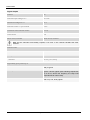
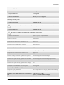
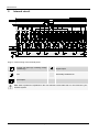
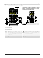
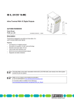
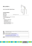
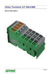
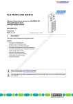
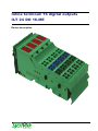
Inline terminal: 16 digital outputs ILT 24 DO 16-ME Device description Preliminary Disclaimer / Imprint This manual is intended to provide support for installation and usage of the device. The information is believed to be accurate and reliable. However, SysMik GmbH Dresden assumes no responsibility for possible mistakes and deviations in the technical specifications. SysMik GmbH Dresden reserves the right to make modifications in the interest of technical progress to improve our modules and software or to correct mistakes. We are grateful to you for criticism and suggestions. Further information (device description, available software) can be found on our homepage www.sysmik.de. Please ask for latest information. SysMik disclaims all warranties in case of improper use or disassembly and software modifications not described in this document or when using improper or faulty tools. Commissioning and operation of the device by qualified personnel only. All applicable regulations have to be observed. SysMik® and the SysMik logo are registered trademarks of SysMik GmbH Dresden. IPOCS™ is © trademark of SysMik GmbH Dresden. "Networking Together!" is subject to copyright of SysMik GmbH Dresden. All other trademarks mentioned in this document are registered properties of their owners. These and further trademarks are used in this document but not marked for better readability. No part of this document may be reproduced or modified in any form without prior written agreement with SysMik GmbH Dresden. Copyright © 2014 by SysMik GmbH Dresden SysMik GmbH Dresden Tel + 49 (0) 351 – 4 33 58 – _0 Bertolt-Brecht-Allee 24 Fax + 49 (0) 351 – 4 33 58 – 29 01309 Dresden E-Mail (Sale) E-Mail (Support) Germany 2 Homepage sysmik.de [email protected] [email protected] www.sysmik.de ILT 24 DO 16-ME Contents Contents 1 Description 4 2 Order information 4 3 Technical data 5 4 Local diagnostic and status indicators and terminal point assignment 11 5 Internal circuit 12 6 Connection notes and examples 13 ILT 24 DO 16-ME sysmik.de 3 Description / Order information 1 Description Note: This device description is only valid in association with the IL SYS INST UM user manual. Make sure you always use the latest documentation – it can be downloaded at www.sysmik.de. The terminal is designed for use within an -Inline station. It is used to -acquire digital output signals. Features Connections for 16 digital actuators Connection of actuators in 2 and 3--wire technology Nominal current per output: 0.5 mA Total current of the terminal:- 8.0 A Short-circuit and overload protected -outputs Diagnostic and status indicators Bild 1: Inline-Klemme ILT 24 DO 16-ME 2 Order information Description Type Part number Pcs./Pkt. Terminal with four digital outputs; including connector and labeling field ILT 24 DO 16-ME 1225-100516-01-8 1 4 sysmik.de ILT 24 DO 16-ME Tecnical Data 3 Technical data General Data Housing dimensions (width x height x depth) 48.8 mm x 120 mm x 71.5 mm Weight 130 g (without connectors) Operating mode Process data mode with 1 word Transmission speed 500 kBaud Connection method for sensors 2 and 3-wire technology Permissible temperature (operation) -25 °C to +55 °C Permissible temperature (storage/transport) -25 °C to +85 °C Permissible humidity (operation/storage/transport) 10 % to 95 %, accordnig to DIN EN 61131-2 Permissible air pressure (operation/storage/transport) 70 kPa to 106 kPa (up to 3000 m above sea level) Degree of protection IP20 according to IEC 60529 Protection class Class 3 according to VDE 0106, IEC 60536 Interface Local bus Via data routing Current consumption from the local bus 90 mA maximum Power Consumption Power consumption from the local bus 0.675 W maximum Segment supply voltage US 24 V DC (nominal value) Nominal current consumption at US 8 A (16 x 0.5 A) maximum Supply of the Module Electronics and I/O Through Bus Terminal/Power Terminal Connection method ILT 24 DO 16-ME Through potential routing sysmik.de 5 Technical Data Digital Outputs Number 16 Nominal output voltage UOUT 24 V DC Differential voltage for Inom ≤1 V Nominal current Inom per channel 0.5 A Tolerance of the nominal current +10 % Total current 8A Short circuit; overload Short circuit; overload Note: All four channels are thermally coupled, i.e.an error in one channel canaffect the other channels. Nominal Load Ohmic 48 Ω / 12 W Lamp 12 W Inductive 12 VA (1,2 H, 50 Ω) Signal delay upon power up of: 6 - Ohmic nominal load 500 µs typical - Lamp nominal load typisch 100 ms typical (with switching frequencies up to 8 Hz; above this frequency the lamp load responds like an ohmic load) - Inductive nominal load 100 ms (1.2 H, 50 Ω) typical sysmik.de ILT 24 DO 16-ME Tecnical Data Signal delay upon power down of: - Ohmic nominal load 1 ms typical - Lamp nominal load 1 ms typical - Inductive nominal load 50 ms (1.2 H, 50 Ω) typical Switching frequency with: - Ohmic nominal load maximal 300 Hz Note: This switching frequency is limited by the selected data rate, the number of devices, the bus structure, the software and the control or computer system used. - Lamp nominal load maximal 300 Hz Note: This switching frequency is limited by the selected data rate, the number of devices, the bus structure, the software and the control or computer system used. - Induktive nominal load 0,5 Hz (1.2 H, 50 Ω) maximum Overload response Auto restart Response time with ohmic overload (12 W) appr. 3 s Restart frequency with ohmic overload appr. 400 Hz Restart frequency with lamp overload appr. 400 Hz Response with inductive overload Output may be damaged Response time in the event of a short circuit appr. 3 s Reverse voltage protection against short pulses Protected against reverse voltages Resistance to permanently applied reverse voltages Protected against reverse voltages, permissible current 2 A maximum Resistance to permanently applied surge voltage no Validity of output data after connecting the 24 V voltage supply (power up) 5 ms typical Response upon power down The output follows the supply voltage without delay Limitation of the voltage induced on circuit interruption -15 V ≤ Udemag ≤ -46 V (Udemag = demagnetization voltage) ILT 24 DO 16-ME sysmik.de 7 Technical Data One-time unsolicited energy 400 mJ maximum Protective circuit type integrated 45 V-Zener diode in the output chip Overcurrent shutdown 0,7 A minimum Output current when switched off 300 µA maximum Output voltage when switched off 2 V maximum Output current with ground connection interrupt 25 mA maximum Switching power with ground connection interrupt 100 mW at 1 kΩ load resistance, typical Inrush current with lamp load 1.5 A for 20 ms maximum Output Characteristic Curve When Switched On (Typical) Output Current (A) Differential -Output Voltage (V) 0 0 0.1 0.04 0.2 0.08 0.3 0.12 0.4 0.16 0.5 0.20 Power Dissipation Formula to Calculate the Power Dissipation of the Electronics Where: PTOT = Total power dissipation in the terminal n= Index of the number of set outputs n = 1 to 16 ILn = Load current of output n Power dissipation of the housing PHOU 8 2.7 W, maximum (within the permissible operating temperature) sysmik.de ILT 24 DO 16-ME Tecnical Data Limitation of Simultaneity, Derating Ambient Temperature T A Maximum Load Current at 100% Simultaneity Maximum Load Current at 75% Simultaneity -25 °C ≤ TA < +40 °C 0.50 A 0.50 A +40 °C ≤ TA < +45 °C 0.45 A 0.50 A +45 °C ≤ TA < +50 °C 0.40 A 0.50 A +50 °C < TA ≤ +55 °C 0.35 A 0.50 A With 100% simultaneity, a load current of 0.4 A for each channel is permissible up to 50°C (ambient temperature range) and a load current of 0.35 A from 50°C and higher. If a maximum of twelve channels are used simultaneously in the entire ambient temperature range (75% simultaneity, maximum) a load current of 0.5 A can be tapped. Safety Equipment Overload/short circuit in segment circuit Electronic; with 4-channel driver Surge voltage Protective elements in the power terminal; protection up to 33 V DC Polarity reversal of the supply voltage Protective elements in the power terminal; The supply voltage must be protected. The power supply unit should be able to supply 4 times (400 %) the -nominal current of the fuse. Reverse voltage Integrated reverse voltage protection ILT 24 DO 16-ME sysmik.de 9 Technical Data Electrical Isolation/Isolation of the Voltage Areas To provide electrical isolation between the logic level and the I/O area, it is necessary to supply the station bus terminal and the digital output terminal described here using the bus terminal or a power terminal from separate power supply units. Interconnection of the power supply units in the 24 V area is not permitted. (See also user manual.) Common Potentials The 24 V main voltage, 24 V segment voltage, and GND have the same potential. FE is a separate potential area. Separate Potentials in the System Consisting of Bus Terminal Module/Power Terminal and I/O Terminal - Test Distance - Test Voltage 5 V supply outgoing remote bus / 7.5 V supply (bus logic) 500 V AC, 50 Hz, 1 min. 5 V supply outgoing remote bus / 7.5 V supply (bus logic) 500 V AC, 50 Hz, 1 min. 7.5 V supply (bus logic) / 24 V supply (I/O) 500 V AC, 50 Hz, 1 min. 24 V supply (I/O) / functional earth ground 500 V AC, 50 Hz, 1 min. Error Messages to the Higher-Level Control or Computer System Short circuit/overload of an output yes An error message is generated when an output is short circuited and switched on. In addition, the diagnostic LED (D) flashes on the terminal at 2 Hz (medium) under these conditions. Falling below or exceeding the operating voltage 10 no sysmik.de ILT 24 DO 16-ME Local diagnostic and status indicators and terminal point assignment 4 Local diagnostic and status indicators and terminal point assignment Designation Color Meaning D green Diagnostics 1, 2, 3, 4 (for each connector) Yellow Status indicators of the outputs Funktion identification Red Housing / connector color Green housing, green connectors – coded according to function Terminal assignment per connector: Fig. 2: local diagnostic and status indicators / Terminal point assignment ILT 24 DO 16-ME Terminal point Assignment x.1 Signal output (OUT) x.2 Ground contact (GND) for 2 and 3-wire termination x.3 FE connection for 3-wire termination x.4 Signal output (OUT) sysmik.de 11 Internal circuit 5 Internal circuit Fig. 3: Internal wiring of the terminal points Protocol chip (bus logic including voltage conditioning) Digital output LED Electrically isolated area Optocoupler Note: Other symbols are explained in the user manual IL SYS INST UM or in the manual of your used bus system. 12 sysmik.de ILT 24 DO 16-ME Connection nots and examples 6 Connection notes and examples The actuators can also be connected via external busbars. -Ensure that the actuators and US are supplied from the same voltage- supply A 3-wire connection B 2-wire connection Note: When connecting the sensors, observe the assignment of the terminal points to the process data (see Terminal Point Assignment). Fig. 4: Typical actuator connection ILT 24 DO 16-ME Note: Ensure that the Inline system ground is reference for at least the ground when using external busbars. Fig. 5: Typical connection of sensors when using external busbars sysmik.de 13