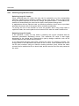
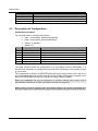
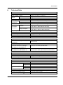
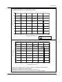
1
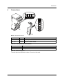
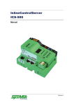
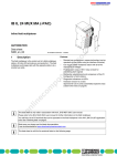
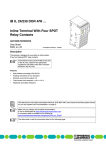
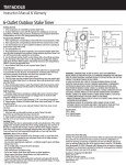
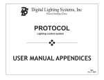
Inline Terminal ILT 24/230 DOR 4/HC Device Description Rev. 2 Disclaimer / Impressum This manual is intended to provide support for installation and usage of the device. The information is believed to be accurate and reliable. However, SysMik GmbH Dresden assumes no responsibility for possible mistakes and deviations in the technical specifications. SysMik GmbH Dresden reserves the right to make modifications in the interest of technical progress to improve our modules and software or to correct mistakes. We are grateful to you for criticism and suggestions. Further information (device description, available software) can be found on our homepage www.sysmik.de. Please ask for latest information. SysMik disclaims all warranties in case of improper use or disassembly and software modifications not described in this document or when using improper or faulty tools. Commissioning and operation of the device by qualified personnel only. All applicable regulations have to be observed. ® SysMik and the SysMik logo are registered trademarks of SysMik GmbH Dresden. All other trademarks mentioned in this document are registered properties of their owners. These and further trademarks are used in this document but not marked for better readability. No part of this document may be reproduced or modified in any form without prior written agreement with SysMik GmbH Dresden. Copyright © 2007 by SysMik GmbH Dresden SysMik GmbH Dresden Bertolt-Brecht-Allee 24 01309 Dresden Germany 2 Tel Fax E-Mail (sales) E-Mail (support) Homepage + 49 (0) 351 - 4 33 58 - 0 + 49 (0) 351 - 4 33 58 - 29 [email protected] [email protected] http://www.sysmik.com ILT 24/230 DOR 4/HC Inhalt Inhalt 1 Overview 4 2 Order Information 4 3 Safety Notes 5 3.1 Safety Notes for Inline Terminals Used in Areas Outside the SELV Area (AC Area) 5 3.2 Correct Usage 5 3.3 Installation Instructions and Notes 5 3.4 Special Features of the Terminal 6 4 Connections 7 4.1 Wiring Guidelines 8 4.2 Terminal Assignment 9 4.3 Typical Terminal Arrangement 9 4.4 Interference Suppression Measures on Inductive Loads/Switching Relays 11 4.4.1 Circuit versions: 12 4.4.2 RC Circuit Versions: 13 4.4.3 Switching Large AC/CD Loads 14 5 Communication 15 5.1 Programming Data / Configuration data 15 5.2 Process Data Structure 15 5.3 Description of Configuration 16 6 Technical Data 17 7 Literature 22 ILT 24/230 DOR 4/HC 3 Overview / Order information 1 Overview The four channel relay terminal ILT 24/230 DOR 4/HC is designed for use within the modular Inline-I/O system of Phoenix Contact. Features: electrically isolated connections for 4 actuators rated current 10 A; at single outputs up to 16 A with derating inrush current 30 A, max. inrush current (20 ms) 80 A safe isolation according to EN 50178 low power consumption due to bistable relays 3 different operating modes configurable for each output communication on local bus via process data indicators for diagnostics and status Modes of operation: monostable, default state opened (delivery status) The contact is opened when power supply or bus communication fails. This is the behaviour of a normal make contact. monostable, default state closed The contact is closed when power supply or bus communication fails. This behaviour is similar to a break contact, but the control via the process data is not inverted. The command "Set" always closes contact x if bit "relay x" is set - independent of the operation mode. bistable The contact holds its current state when power supply or bus communication fails. 2 Order Information Device Description Part number IB IL 24/230 DOR 4/HC-PA Inline terminal with four relay outputs, 1225-100250-04-2 C complete with connectors and labelling fields Accessories Inline distance terminal, complete with connectors and labelling fields, 1 set (2 IB IL DOR LV-SET-PAC 1225-100491-01-8 pieces) Table 2.1: Order Information 4 ILT 24/230 DOR 4/HC Safety Notes 3 Safety Notes 3.1 Safety Notes for Inline Terminals Used in Areas Outside the SELV Area (AC Area) Only qualified personnel may work on Inline terminals in the AC area. Qualified personnel are people who, because of their education, experience and instruction, and their knowledge of relevant standards, regulations, accident prevention, and service conditions, have been authorized by those responsible for the safety of the plant to carry out any required operations, and who are able to recognize and avoid any possible dangers (Definitions of skilled workers according to EN 50110-1:1996). Note: The instructions given in this data sheet as well as in the user manual IL SYS INST UM E [1] or the Inline system manual for your bus system must be strictly observed during installation and startup. Technical modifications reserved. 3.2 Correct Usage The terminal is only to be used within an Inline station as specified in this data sheet as well as the IL SYS INST UM E user manual or the Inline system manual for your bus system. SysMik accepts no liability if the device is used for anything other than its designated use. Dangerous contact voltage Please note that there are dangerous voltages when switching circuits that do not meet SELV requirements. Only remove and insert the AC terminals when the power supply is disconnected. When working on terminals and wiring, always switch off the supply voltage and ensure it cannot be switched on again. 3.3 Installation Instructions and Notes Install the system according to the requirements of EN 50178! Use grounded AC-networks Inline AC terminals must only be operated in grounded AC networks. Read the user manual Observe the installation instructions and notes in the IL SYS INST UM E user manual or the Inline system manual for your bus system, especially the notes on the low voltage area. ILT 24/230 DOR 4/HC 5 Safety Notes 3.4 Special Features of the Terminal The terminal can be used to switch loads up to 230 V. Note: The terminal interrupts the potential jumpers U M, US, and GND (24 V area) or L and N (120 V / 230 V areas). If required, these supply voltages must be resupplied / provided using an appropriate power terminal after the relay terminal. Switching loads in the 230 V area To switch voltages outside the SELV area, an AC area must be created corresponding to the installation instructions and notes provided in the user manual. Operation on an AC network Operate the terminal from a single phase on an AC network! Switching voltages that are not available in the segment A relay terminal can be used to switch voltages that are not available in the segment in which the terminal is located (e.g., switching 230 V AC within a 24 V DC segment). In this case, place a distance terminal before and after the terminal (see Order Information). The isolating distances between the individual areas are thus maintained. See also Connection examples in chapter 4.3 6 ILT 24/230 DOR 4/HC Connections 4 Connections 1 D 3 DOR4/ 2 4 HC 1x 1.1 2.1 1.2 2.2 1.3 2.3 1.4 2.4 4x Bild 4.1: Terminal connections Indicator Color Descriptiong D green 1, 2, 3, 4 yellow Bus diagnostics Status indication of output LED on = contact closed Table 4.1: Local diagnostic and status indicators Terminal point Assignment 1.2, 2.2 1.3, 2.3, 1.4, 2.4 common contact closing contact Table 4.2: Terminal assignment Terminal points not defined in table 4.2 must not be used. ILT 24/230 DOR 4/HC 7 Connections Local bus OPC UL+ UANA UL4 µC EEPROM 4 OPC µC EEPROM Protocol chip LED Microcontroller Current limiter EEPROM Energy storage Relay driver bistabile relay Fig. 4.2: Functional overview 4.1 Wiring Guidelines For load currents of more than 8 A it is strongly recommended to use 2 wires (2x 1,5 mm2) in parallel. Single wire connection is allowed too, observing the derating conditions, but the correct connectors have to be used (included in delivery). These connectors are internally connected between terminal points 1.2 and 2.2, 1.3 and 2.3, 1.4 and 2.4. The load current should be evenly distributed when using two wires in parallel. This means both connections should have the same resistance. The following measures apply: equal wire cross-section of 1.5 mm2 (copper) equal wire length equal number of additional contact points Attention: If the internally connected terminal points 1.3, 2.3, 1.4, 2.4 are used as a terminal block, the current of each terminal point must not exceed 8 A. 8 ILT 24/230 DOR 4/HC Connections 4.2 Terminal Assignment 1 1 3 DOR4/ 2 3 4 D 2 4 HC 1.1 2.1 1.1 2.1 1.1 2.1 1.1 2.1 1.2 2.2 1.2 2.2 1.2 2.2 1.2 2.2 1.3 2.3 1.3 2.3 1.3 2.3 1.3 2.3 1.4 2.4 1.4 2.4 1.4 2.4 1.4 2.4 main contact main contact N/O contact N/O contact Fig. 4.2.1: Terminal assignment 4.3 Typical Terminal Arrangement 1 1 2 D 2 DO2 1 3 DOR4/ 3 UM D D 2 4 PWRIN HC AI2 1.1 2.1 1.1 2.1 1.1 2.1 1.1 2.1 1.1 2.1 1.1 2.1 1.1 2.1 1.2 2.2 1.2 2.2 1.2 2.2 1.2 2.2 1.2 2.2 1.2 2.2 1.2 2.2 1.3 2.3 1.3 2.3 1.3 2.3 1.3 2.3 1.3 2.3 1.3 2.3 1.3 2.3 1.4 2.4 1.4 2.4 1.4 2.4 1.4 2.4 1.4 2.4 1.4 2.4 1.4 2.4 Fig. 4.3.1: Switching 24 V within a 24 V area 1: 2: 3: 24 V area consisting of station head and I/O terminals relay terminal in the 24 V area 24 V area consisting of power terminal and I/O terminals ILT 24/230 DOR 4/HC 9 Connections 1 1 2 D 2 1 3 DOR4/ DO2 3 UM D D 2 4 HC PWRIN AI2 1.1 2.1 1.1 2.1 1.1 2.1 1.1 2.1 1.1 2.1 1.1 2.1 1.1 2.1 1.1 2.1 1.1 2.1 1.2 2.2 1.2 2.2 1.2 2.2 1.2 2.2 1.2 2.2 1.2 2.2 1.2 2.2 1.2 2.2 1.2 2.2 1.3 2.3 1.3 2.3 1.3 2.3 1.3 2.3 1.3 2.3 1.3 2.3 1.3 2.3 1.3 2.3 1.3 2.3 1.4 2.4 1.4 2.4 1.4 2.4 1.4 2.4 1.4 2.4 1.4 2.4 1.4 2.4 1.4 2.4 1.4 2.4 Fig. 4.3.2: Switching 230 V within a 24 V area 1) 24 V area consisting of station head and I/O terminals 2) relay terminal separated from the 24 V area by Inline separation terminals 3) 24 V area consisting of power terminal and I/O terminals Figures 3.3.1 and 3.3.2 illustrate the two basic types of application: with and without separation terminals. Separation terminals must be used to ensure the required safety clearance between different voltage areas of an Inline station, for example between 230 V AC and 24 V SELV. If the relay terminal shall switch a 230 V load within a 24 V area (or vice versa), separation terminals are necessary. On the other hand, if the relay terminal is used to switch the same voltage as in the adjoining area, no additional separation terminals are needed. Because the relay terminal interrupts the voltage jumpers UM, US, and GND (in 24 V areas) or L and N (in 120 V or 230 V areas), these voltages have to be re-supplied using an apropriate power terminal after the relay terminal, if required. Note: On AC networks, operate the terminal from a single phase only. To use several phases, separate areas have to be built using separation terminals - one area for each phase. 10 ILT 24/230 DOR 4/HC Connections 4.4 Interference Suppression Measures on Inductive Loads/Switching Relays Each electrical load is a mix of ohmic, capacitive, and inductive elements. Depending on the proportion of the elements, switching these loads results in a larger or smaller load on the switch contact. In practice, loads are often used with a large inductive element, such as contactors, solenoid valves, motors, etc. Due to the energy stored in the coils, voltage peaks of up to a few thousand volts may occur when the system is switched off. These high voltages cause an arc on the controlling contact, which may destroy the contact through material vaporization and material migration. This pulse, which is similar to a square wave pulse, emits electromagnetic pulses over a wide frequency range (spectral elements reaching several MHz) with a large amount of power. To prevent such arcs from occurring, the contacts/loads must be fitted with protective circuits. In general, the following protective circuits can be used: contact protective circuit load protective circuit combination of both protective circuits A B Fig. 4.4.1: Contact protective circuit (A), load protective circuit (B) If sized correctly, these circuit versions do not differ greatly in their effectiveness. In principle, safety equipment should intervene directly at the source of the interference. The following points speak in favor of a load protective circuit: When the contact is open, the load is electrically isolated from the operating voltage. It is not possible for the load to be activated or to "stick" due to undesired operating currents, e.g., from RC elements. Shutdown voltage peaks cannot be coupled in control lines that run in parallel. Phoenix Contact provides protective circuit solutions in the form of terminals or electronic housing (see "CLIPLINE" or "TRABTECH" catalogs). Additional information is available on request. In addition to this, today the majority of contactor manufacturers offer diode, RC or varistor elements that can be snapped on. For solenoid valves, connectors with an integrated protective circuit can be used. ILT 24/230 DOR 4/HC 11 Connections 4.4.1 Circuit versions Load wiring Diode Additional drop delay Defined inductive voltage limitation Bipolar attenuation -+ Last Load UD large yes (UD) no Series connection Diode / Zener diode -+ Last Load UZD medium to small yes (UZD) no Suppressor diode -+ (~) (~) Last Load Varistor UZD medium to small yes (UZD) yes -+ (~) (~) Last Load VDR UVDR medium to small yes (UVDR) yes Advantages / Disadvantages Advantages: - easy implementation - cost effective - no critical sizing - small inductive voltage Disadvantages: - attenuation only via load resistance - large drop delay Advantages: - no critical sizing Disadvantages: - attenuation only above UZD Advantages: - cost effective - no critical sizing - limiting fast peaks - suitable for AC voltage Disadvantages: - attenuation only above UZD Advantages: - high energy absorption - no critical sizing - suitable for AC voltage Disadvantages: - attenuation only above UVDR Table 4.4.1.1: Circuit versions 12 ILT 24/230 DOR 4/HC Connections 4.4.2 RC Circuit Versions RC Series Circuit Load wiring Additional drop delay Defined inductive voltage limitation Bipolar attenuation RC combination -+ (~) (~) R Last Load URC C medium to small no yes Advantages / Disadvantages Advantages: - HF-attenuation due to energy absorption - suitable for AC voltage - level-independent attenuation - compensating reactive current Disadvantages: - exact sizing required - high inrush current Table 4.4.2.1: RC series circuit Sizing: C ≈ LLoad / (4 × RLoad2) R ≈ 0.2 x RLoad Capacitor: Resistor: RC Parallel Circuit With Series Diode Load wiring Additional drop delay Defined inductive voltage limitation Bipolar attenuation RC combination with diode -+ Last Load URC C medium to small no R no Advantages / Disadvantages Advantages: - HF-attenuation due to energy absorption - level-independent attenuation - current reversing not possible Disadvantages: - exact sizing required - only suitable for DC voltage Table 4.4.2.2: RC parallel circuit with series diode Sizing: Capacitor: Resistor: ILT 24/230 DOR 4/HC C ≈ LLoad / (4 × RLoad2) R ≈ 0.2 x RLoad 13 Connections 4.4.3 Switching Large AC/CD Loads Switching Large AC Loads: When switching large AC loads, the relay can be operated up to the corresponding maximum values for the switching voltage, current, and power. The arc that occurs during shutdown depends on the current, voltage, and phase relation. This shutdown arc switches off automatically the next time the load current passes through zero. In applications with an inductive load, an effective protective circuit must be provided, otherwise the service life of the system will be reduced considerably. To prolong the life of the terminal as much as possible when using lamp loads or capacitive loads, the current peak must not exceed 30 A when the load is switched on. Switching Large DC Loads In DC operation, a relay can only switch a relatively low current compared with the maximum permissible alternating current. This maximum DC value is also highly dependent on the voltage and is determined in part by design conditions, such as the contact distance and contact opening speed. A non-attenuated inductive load further reduces the values for switching currents. The energy stored in the inductance can cause an arc to occur, which forwards the current via the open contacts. Using an effective contact protection circuit, almost the same currents can be switched as for an ohmic load, and the service life of the relay contact is the same. 14 ILT 24/230 DOR 4/HC Communication 5 Communication 5.1 Programming Data / Configuration data Attribute value ID code Length code Input address area Output address area Parameter channel (PCP) Register length (bus) BFhex (191dez) 81hex 1 Byte 1 Byte 0 Byte 1 Byte Table 5.1.1: INTERBUS programming data / configuration data 5.2 Process Data Structure Output-process data byte 7 0 6 5 command 4 3 relay 4 2 relay 3 1 relay 2 0 relay 1 Table 5.2.1: Structure of output process data byte Bit Command Description set read back configuration 1 (relay mode) set relays: 0 = opened, 1 = closed read back current logical relay state relay mode: 0 = monostable, 1 = bistable, must be followed by configuration 2 1 configuration 2 (default state) default state: 0 = opened, 1 = closed, only effective for relays in monostable mode, has to be sent after configuration 1 refresh of all relays, coded in bit 0: bit 0 = 0 refresh off bit 0 = 1 refresh every 120s bits 1-3 are reserved and must be 0 6 5 4 0 0 0 0 0 1 0 1 0 0 1 1 0 0 configuration 3 (refresh) 1 1 1 0 1 1 1 0 1 reserved Table 5.2.2: Command field in output process data byte Input process data byte 7 6 error 5 command 4 3 2 relay 4 1 relay 3 0 relay 2 relay 1 Table 5.2.3: Structure of input process data byte The input process data byte mirrors the output byte except bit 7, which indicates an error when set. ILT 24/230 DOR 4/HC 15 Communication Command Error cause Set Configuration 2 Configuration 3 insufficient power supply for switching command configuration 1 must be sent first invalid parameter (bits 1-3 not 0) Table 5.2.4: Possible error causes 5.3 Description of Configuration Configuration example The terminal shall be configured as follows: relay 1: monostable, default state opened relay 2: monostable, default state closed relays 3, 4: bistable refresh: off Step Process data Explanation 1 2 3 4 5 6 OUT = 2Chex wait for IN = 2Chex OUT = 32hex wait for IN = 32hex OUT = 40hex wait for IN = 40hex configuration 1 (relay mode): relays 3 and 4 bistable wait for confirmation configuration 2 (default state): relay 2 closed wait for confirmation configuration 3: refresh off wait for confirmation Table 5.3.1: Example of configuration sequence The relay terminal saves the configuration in a nonvolatile memory (EEPROM). It is therefore not necessary to configure the terminal anew following a loss of power supply or a bus reset. The configuration is written to EEPROM when the power supply starts to fail, and only if the configuration data has actually changed. Even multiple configuration changes do not lead to an EEPROM write cycle as long as the supply voltage is stable. Note: Each EEPROM cell has an endurance of at least 100,000 write cycles. This is approximately equivalent to 13 write cycles daily over a period of 20 years. Note: If there are relays in bistable mode, their switching state is also written to EEPROM when the power supply fails - provided that the current state is different from the previously saved one. 16 ILT 24/230 DOR 4/HC Technical Data 6 Technical Data General data Housing dimensions (width x height x depth) with connectors Weight without connectors Operating mode operation Permissible temperature storage / transport Permissible humidity Permissible air pressure operation storage / transport Degree of protection Inline connector Connection type Rated cross section Insulation stripping length 48.8 mm x 120 mm x 71.5 mm (1.921 in. x 4.724 in. x 2.815 in.) 230 g 167 g process data operation with 1 byte -10 °C to +55 °C (14 °F to +131 °F) -25 °C to +85 °C (-13 °F to +185 °F) 75 % on average, 85 % occasionally (non condensing) 80 kPa to 106 kPa (up to 2000 m / 6562 ft.above sea level) 70 kPa to 106 kPa (up to 3000 m / 9843 ft. above sea level) IP20 according to IEC 60529 spring-clamp 2 2 0.2 mm to 1.5 mm , AWG 24-16 8 mm Deviation from Inline specification Permissible lowest operation temperature Mechanical requirements Vibration test sinusoidal vibrations according to IEC 60068-2-6; EN 60068-2-6 Shock test according to IEC 60068-2-27; EN 60068-2-27 -10 °C (14 °F) 2g load, 2 h for each space direction 2g load over 11 ms, half sinusoidal wave, three shocks in each space direction and orientation Interfaces INTERBUS local bus Connection Transmission speed through data routing 500 kBaud Power consumption Communications power UL Current consumption at relays off UL relays on relays off Power consumption at UL relays on I/O supply voltage UANA Current consumption at UANA Power consumption at UANA ILT 24/230 DOR 4/HC 7.5 V 23 mA 34 mA 0.17 W 0.26 W 24 V DC 10 mA, max. 55 mA when switching (duration approx. 25 ms per switched relay) max. 0.46 W 17 Technical Data Supply of the module electronics through the bus coupler/power terminal Connection method potential routing Relay output Number Contact material Limiting continuous current (at maximum ambient temperature) Maximum switching voltage Maximum switchin power Minimum load Peak inrush current (20 ms) Max. switching without load frequency at nominal load Bounce time Operate- / release time Common potentials Mechanical life Examples of electrical life Small load 24 V DC, 100 mA Ohmic load, 250 V AC, 16 A Incandescant lamp 1150 W, 230 V AC, 5 A, (Ion = 75 A) Incandescent lamp 1000 W, 250 V AC, 4 A Incandescant lamps 250 V AC, 5 x 60 W Fluorescent lamps not or serial compensated 14 x 58 W Fluorescent lamps duo circuit 7 x (2 x 58 W) Fluorescent lamps parallel compensated (7 µF) 1 x (2 x 58 W) Energy saving lamps with conventional ballast 40 x 25 W Energy saving lamps with electronic ballast 3 x 18 W Electrical motor 250 V AC, 16 A, cos φ = 0.6 compressor, 230 V AC, Ion_peak ≤ 21 A, Ioff = 3,5 A, cos φ = 0.5 18 4 AgSnO2 2 8 A single wire connection (1.5 mm ), 2 10 A double wire connection (2x 1.5 mm ) 253 V AC, 250 V DC 4000 VA 12 V; 100 mA 80 A 60 cycles/minute 6 cycles/minute typ. 2 ms typ. 5 ms / 4 ms all contacts electrically isolated 6 typ. 30 * 10 cycles 7 > 10 cycles typ. 100,000 cycles > 20,000 cycles typ. 80,000 cycles typ. 500,000 cycles typ. 50,000 cycles typ. 50,000 cycles typ. 50,000 cycles typ. 40,000 cycles typ. 40,000 cycles typ. 85,000 cycles typ. 230,000 cycles ILT 24/230 DOR 4/HC Technical Data Maximum switching current depending on temperature, all outputs simultaneous and with equal currents 16 14 Current in A 12 10 8 6 4 2 0 30 35 40 45 50 Ambient temperature in °C 55 60 Connection 2x 1.5mm² Connection 1x 1.5mm² Maximum switching current of a single output depending on temperature 18 16 14 Max. current in A 12 10 8 6 4 2 0 30 35 40 45 50 55 60 Ambient temperature in °C In case of unsymmetric loads, a higher current is acceptable on single outputs. The following conditions have to be fulfilled: 2 double wire connection 2x 1,5 mm in case of currents > 8 A the maximum current must not exceed the value from the diagram above ILT 24/230 DOR 4/HC 19 Technical Data the load currents of the separate outputs have to fulfill the condition 2 2 2 2 2 IL1 + IL2 + IL3 + IL4 ≤ 400 A Example: What max. current is acceptable at 50 °C and what current is allowed at the other three outputs? The diagram shows an allowed load current of max. 14 A. This leaves for the other outputs: 2 2 2 2 2 400 A - (14 A) = 400 A - 196 A = 204 A Therefore, even a second output could be loaded with 14 A and the other two otputs with 2 A each: 2 2 2 2 2 2 2 (14 A) + (2 A) + (2 A) = 196 A + 4 A + 4 A = 204 A Alternatively, in case of equal load on the remaining three outputs, these could each carry a maximum current of: 2 2 √(204 A / 3) = √(68 A ) ≈ 8.2 A Max. DC load breaking capacity In case of DC loads, the max. DC load breaking capacity may further limit the max. allowed current. 300 DC voltage [V] 200 resistive load 100 50 40 30 20 10 0.1 0.2 0.5 1 2 5 10 20 DC current [A] 20 ILT 24/230 DOR 4/HC Technical Data Power dissipation Equation to calculate the power dissipation in the terminal PEL = PBUS + PREL + PL PBUS = 0.5 W PREL = 66 mWs x (f1 + f2 + f3 + f4) 2 2 2 2 PL = (IL1 x D1 + IL2 x D2 + IL3 x D3 + IL4 x D4) x 0.006 Ω Where PEL PBUS PREL PL fn ILn Dn total power dissipation of the terminal power dissipation through bus operation power dissipation through switching relays power dissipation through the load current via the contacts switching frequency (cycles per time) of output n load current of output n duty ratio of load current on output n: Dn = ton x fn Safety devices None Error messages to higher-level control system Peripheral error in case of I/O supply voltage (UANA) failure Air and creepage distances (according to EN 50178, VDE 0109, VDE 0110) Isolating distance Relay contact / bus logic Contact / contact Contact / PE Air distance ≥ 5.5 mm (0.217 in.) ≥ 3.1 mm (0.122 in.) ≥ 3.1 mm (0.122 in.) Creepage distance ≥ 5.5 mm (0.217 in.) ≥ 3.1 mm (0.122 in.) ≥ 3.1 mm (0.122 in.) Test voltage 4 kV, 50 Hz, 1 min 1 kV, 50 Hz, 1 min 1 kV, 50 Hz, 1 min Table 6.1: Technical data ILT 24/230 DOR 4/HC 21 Literature 7 22 Literature [1] User manual IL SYS INST UM E: "Automation Terminals of the Inline Product Range", Phoenix Contact Phoenix Contact order no. 2698737 [2] User manual IB IL SYS PRO UM: "Configuring and Installing the INTERBUS Inline Product range", Phoenix Contact, Phoenix Contact order no. 2743048 [3] www.phoenixcontact.com [4] www.sysmik.de ILT 24/230 DOR 4/HC