1
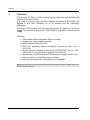
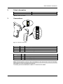
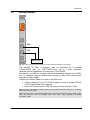
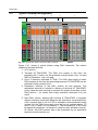
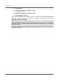
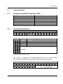
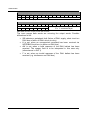
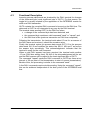
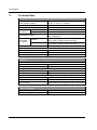
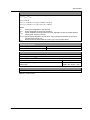
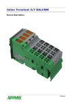
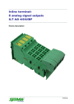
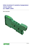
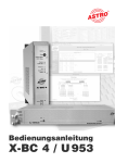
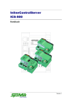
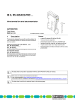
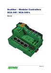
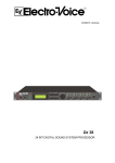
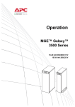
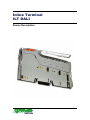
Inline Terminal ILT DALI Device Description Revision 2 Disclaimer / Impressum This manual is intended to provide support for installation and usage of the device. The information is believed to be accurate and reliable. However, SysMik GmbH Dresden assumes no responsibility for possible mistakes and deviations in the technical specifications. SysMik GmbH Dresden reserves the right to make modifications in the interest of technical progress to improve our modules and software or to correct mistakes. We are grateful to you for criticism and suggestions. Further information (device description, available software) can be found on our homepage www.sysmik.de. Please ask for latest information. SysMik disclaims all warranties in case of improper use or disassembly and software modifications not described in this document or when using improper or faulty tools. Commissioning and operation of the device by qualified personnel only. All applicable regulations have to be observed. © ALTO™ und IPOCS™ are trademarks of SysMik GmbH Dresden. "Networking Together!" is subject to copyright of SysMik GmbH Dresden. All other trademarks mentioned in this document are registered properties of their owners. These and further trademarks are used in this document but not marked for better readability. No part of this document may be reproduced or modified in any form without prior written agreement with SysMik GmbH Dresden. Copyright © 2007 by SysMik GmbH Dresden SysMik GmbH Dresden Bertolt-Brecht-Allee 24 01309 Dresden Germany 2 Tel Fax E-Mail (sales) E-Mail (support) Homepage + 49 (0) 351 - 4 33 58 - 0 + 49 (0) 351 - 4 33 58 - 29 [email protected] [email protected] http://www.sysmik.de ILT DALI Content Content ILT DALI 1 Overview 4 2 Order Information 5 3 Connections 5 3.1 Wiring Guidelines 6 3.2 Wiring Example 7 3.3 Typical Terminal Arrangement 8 4 Communication 11 4.1 Programming Data/Configuration Data 11 4.2 Process Data Structure 11 4.3 Functional Description 13 5 Technical Data 14 6 Literature 16 3 Overview 1 Overview The terminal ILT DALI is a DALI master for use within the modular Inline-I/O system of Phoenix Contact. It is used to control lamps via DALI ballasts according to IEC 60929. As defined in this DALI standard, up to 64 ballasts can be individually addressed. Running a DALI system with this terminal requires an additional DALI bus supply, for example a terminal ILT DALI/PWR or a suitable external power supply. Features: DALI master without integrated DALI bus supply designed for single master operation safe insulation of the DALI bus DALI bus protected against mistakenly connecting mains (up to 250 V AC) can be used as extension to a terminal ILT DALI/PWR (part no. 1225100251-05-6), using the built-in supply of this terminal alternatively, a suitable external DALI bus power supply can be used communication on local bus via process data indicators for diagnostics, transmission and reception Note: This description is only valid in association with the user manual ILT INST PRO UM of Phoenix Contact (see [1]). 4 ILT DALI Order information / Connections 2 Order Information Device Part number ILT DALI 1225-100252-05-3 Table 2.1: Order Information 3 Connections D RxD TxD DALI/PWR 1.1 2.1 1.2 2.2 1.3 2.3 1.4 2.4 Fig. 3.1: Terminal connections Indicator Color Descriptiong D RxD TxD green yellow yellow Bus diagnostics Terminal is receiving data from DALI bus Terminal is sending data to DALI bus Table 3.1: Local diagnostic and status indicators Terminal point Signal Assignment 1.2, 2.2 1.3, 2.3 DA+ DA- DALI bus (positive) DALI bus (negative) Table 3.2: Terminal assignment Note: Terminal points 2.2 and 2.3 are not available on the device itself. They are internally connected to 1.2 and 1.3 inside the connector. Terminal points not defined in table 3.2 must not be used. ILT DALI 5 Connections OPC µC Protocol chip Microcontroller Indicator LED 7,5V 5V Local bus UL+ UANA UL- OPC 7,5V 5V DC/DC converter Rx µC Tx Optocoupler DALI driver Double / reinforced insulation UDALI+ UDALI- DA+ DA- Fig. 3.2: Functional overview 3.1 Wiring Guidelines The voltage drop between transmitter and receiver on the DALI bus must not exceed 2 V at 250 mA. Table 3.1.1 shows wiring recommendations. The maximum lead length between two connected DALI devices should not exceed 300 m. Lead length Minimum cross section < 100 m 100..150 m > 150 m 0.5 mm² (AWG 20) 0.75 mm² (AWG 18) 1.5 mm² (AWG 15) Table 3.1.1: Recommended cross sections of DALI bus wiring Special bus cables (twisted or shielded) are not needed. Linear, star shaped and mixed structures are applicable. Ring shaped structures should be avoided. DALI interface insulation of the electronic ballasts fulfills the requirements of base insulation only. Therefore, SELV (Safety Extra Low Voltage) is not granted on the DALI bus, despite the safe insulation of the ILT DALI. 6 ILT DALI Connections 3.2 Wiring Example D RxD TxD DALI 1.1 2.1 1.2 2.2 1.3 2.3 DA+ DA- 1.4 2.4 DALI bus Fig. 3.2.1: Wiring example (without terminal ILT DALI/PWR and without end terminal) The terminal ILT DALI is typically used as extension to a terminal ILT DALI/PWR (part no. 1225-100251-05-6). Up to 3 DALI extension terminals can be supplied by one terminal ILT DALI/PWR. Alternatively, the DALI bus supply can be accomplished directly via the DALI bus, for example using a suitable power supply or other DALI devices with integrated power supply. Following conditions have to be met on the DALI bus: supply voltage 9.5 V to 22.5 V DC at supply current of at least 135 mA (for full load with 64 DALI ballasts) total short circuit current ≤ 250 mA, response time less than 10µs Note: The DALI bus must be supplied either via the potential routing contact UDALI or directly at the DALI bus (not both)! Observe polarity when connecting external DALI bus supply to the terminal ILT DALI! In this case, the terminal must be isolated from both sides using separation terminals ILT DOR LV-SET. ILT DALI 7 Connections 3.3 Typical Terminal Arrangement 1 3 2 1 D 2 DI2 D RxD D RxD TxD TxD DALI DALI/PWR D RxD TxD DALI 4 5 D RxD D RxD TxD TxD DALI/PWR DALI 1.1 2.1 1.1 2.1 1.1 2.1 1.1 2.1 1.1 2.1 1.1 2.1 1.1 2.1 1.1 2.1 1.1 2.1 1.1 2.1 1.1 2.1 1.1 2.1 1.1 2.1 1.1 2.1 1.2 2.2 1.2 2.2 1.2 2.2 1.2 2.2 1.2 2.2 1.2 2.2 1.2 2.2 1.2 2.2 1.2 2.2 1.2 2.2 1.2 2.2 1.2 2.2 1.2 2.2 1.2 2.2 1.3 2.3 1.3 2.3 1.3 2.3 1.3 2.3 1.3 2.3 1.3 2.3 1.3 2.3 1.3 2.3 1.3 2.3 1.3 2.3 1.3 2.3 1.3 2.3 1.3 2.3 1.3 2.3 1.4 2.4 1.4 2.4 1.4 2.4 1.4 2.4 1.4 2.4 1.4 2.4 1.4 2.4 1.4 2.4 1.4 2.4 1.4 2.4 1.4 2.4 1.4 2.4 1.4 2.4 1.4 2.4 Fig. 3.3.1: Typical Inline station with several DALI terminals Figure 3.3.1 shows a typical station using DALI terminals. The station consists of several sections: 1. 24 V section 2. Terminal ILT DALI/PWR. The DALI bus supply is fed from the preceding 24 V section via the potential routing contact (UM). UM and GND of connector 1 are not used. 3. Up to 3 extension terminals ILT DALI. The DALI bus supply of these DALI masters is fed from the preceding terminal ILT DALI/PWR via the potential routing contacts UDALI. 4. Separation terminal of the DALI section as end terminal. The separation terminal is included in delivery of terminal ILT DALI/PWR. In any case this end terminal is required for proper termination of this DALI section – no matter how many extension terminals (0-3) are used! 5. Next DALI section, starting with terminal ILT DALI/PWR, in example without extension terminals. Because this terminal is not preceded by a 24 V section (that is, no 24 V DC is available via the potential routing contact UM) the DALI bus supply must be fed via terminal points 1.2 and 1.3 (or 2.2 and 2.3) of connector 1. The necessary 24 V DC could be tapped at connector 1 of section 2 (observe max. allowed currents). Of course, this DALI section has to be terminated by an separation terminal as end terminal, too. 8 ILT DALI Connections Important: Every DALI section has to be terminated by the end terminal (included in delivery of terminal ILT DALI/PWR). Otherwise the electrical insulation between UM / US and the DALI bus might be compromised! Note: The DALI busses of section 2 and 3 in fig. 3.3.1 are electrically not insulated among one another. Normally this is no problem. However, if such an insulation is required, the terminal ILT DALI/PWR can not be extended by terminals ILT DALI. On the other hand, the DALI busses of sections 2 and 3 are electrically insulated from the DALI bus in section 5, even if all sections use the same 24 V DC supply UM. 1 1 2 3 4 D RxD D 2 D RxD TxD DI2 5 TxD DALI DALI 1.1 2.1 1.1 2.1 1.1 2.1 1.1 2.1 1.1 2.1 1.1 2.1 1.2 2.2 1.2 2.2 1.2 2.2 1.2 2.2 1.2 2.2 1.2 2.2 1.3 2.3 1.3 2.3 1.3 2.3 1.3 2.3 1.3 2.3 1.3 2.3 1.4 2.4 1.4 2.4 1.4 2.4 1.4 2.4 1.4 2.4 1.4 2.4 Fig. 3.3.2: DALI Inline station when using external DALI bus supply Fig. 3.3.2 shows the station set up for using external DALI power supplies. The supply is accomplished by directly connecting to the DALI bus, for example at the DALI terminal (observe polarity). The station consists of the sections: ILT DALI 9 Connections 1. 24 V section 2. separation terminal ILT DOR LV-SET 3. terminal ILT DALI 4. separation terminal ILT DOR LV-SET 5. next terminal ILT DALI If the DALI terminals are following a 230 V section, the same setup applies. However, the first separation terminal is then rather considered being the end terminal of the 230 V section. Important Note: Every externally supplied DALI terminal, has to be isolated from both sides using a separation terminal set ILT DOR LV-SET (part no. 28 61 64 5; set contains 2 separation terminals). Otherwise there were inadmissible connections due to the potential routing contacts UDALI. The DALI terminal is polarity dependent. Please observe polarity, when connecting an external power supply. 10 ILT DALI Communication 4 Communication 4.1 Programming Data/Configuration Data Attribute Value ID code Length code Input address area Output address area Parameter channel (PCP) Register length (bus) BFhex (191dez) 02hex (2dez) 2 words 2 words 0 byte 2 words Table 4.1.1: INTERBUS programming data / configuration data 4.2 Process Data Structure Output process data word OUT1 15 0 14 0 13 0 12 11 10 9 8 0 TB command 7 0 6 0 5 0 4 0 3 0 2 0 1 0 0 0 Table 4.2.1: Structure of output process data word OUT1 Bit 10 9 8 0 0 0 0 1 1 1 1 0 0 1 1 0 0 1 1 0 1 0 1 0 1 0 1 Command Description idle send repeat DALI bus idle send DALI command send DALI command and repeat after 50 ms reserved Table 4.2.2: Command field in OUT1 Bit 11 (TB – Toggle Bit) of process data word OUT1 is used, when commands with the same command field shall be sent consecutively. Output process data word OUT2 15 14 Y A 13 12 11 10 address byte A A A A 9 8 A S 7 6 5 4 3 2 1 S = 0: data byte S = 1: command byte 0 Table 4.2.3: Structure of output process data word OUT2 ILT DALI 11 Communication Input process data word IN1 15 14 13 12 11 10 9 8 SB K AW F TB command 7 6 7 6 5 4 3 answer 2 1 0 5 4 3 2 1 S = 0: data byte S = 1: command byte 0 Table 4.2.4: Structure of input process data word IN1 Input process data word IN2 15 14 Y A 13 12 11 10 address byte A A A A 9 8 A S Table 4.2.5: Structure of input process data word IN2 The input proces data words are mirroring the output words. Possible differences at IN1: SB indicates a peripheral fault (failure of DALI supply, short circuit on DALI bus or failure of DALI driver circuitry) K is set, when an unsupported command has been received via INTERBUS local bus (no action on DALI bus) AW is set, when a valid response of the DALI ballast has been received. The answer field is to be interpreted in this case only (otherwise as in OUT1) F is set, when an invalid response of the DALI ballast has been received (e.g. interference on DALI bus) 12 ILT DALI Communication 4.3 Functional Description Incoming process data words are checked by the DALI terminal for changes of the command byte (most significant byte of OUT1). For that reason, the toggle bit is usually inverted by the application of the INTERBUS master for each new DALI transaction. OUT2 contains the complete DALI command to be sent on the DALI bus. The data word in OUT2 is not interpreted in any way by the DALI terminal. The terminal starts sending OUT2 to the DALI bus when: a change of the command byte has been detected, and the command byte contains a valid command "send" or "repeat", and the DALI bus is idle (previous transaction on DALI bus completed) Following the transmission, the terminal waits about 10 ms for an answer of the DALI slave and receives it, should the occasion arise. Finally, the terminal copies the process data words OUT 1/2 to the process data words IN 1/2 and modifies the status bits SB, K, AW and F as well as the answer byte accordingly. This acknowledgement indicates that the terminal is ready for the next command. When a valid DALI answer has been received, the terminal waits another ~10 ms (DALI bus settling time). Bit AW of the acknowledgement will be set and the DALI answer will be copied to the least significant byte of OUT1. The command "repeat" sends the DALI command in OUT2 two times at an interval of 50 ms (start of first transmission to start of second transmission). Beside of this, the processing is similar to the command "send". A few DALI commands require double sending. Using the command "repeat", this can be achieved independent of the bus cycles of the INTERBUS local bus. ILT DALI 13 Technical Data 5 Technical Data General data Housing dimensions (width x height x depth) Weight with connectors Operating mode operation Permissible temperature storage / transport Permissible humidity Permissible air pressure operation storage / transport Degree of protection Inline connector Connection type Rated cross sectioin Insulation stripping length 12.2 mm x 120 mm x 71.5 mm (0.48 in. x 4.724 in. x 2.815 in.) 60 g process data operation with 2 words -25 °C to +55 °C (-13 °F to +131 °F) -25 °C to +85 °C (-13 °F to +185 °F) 75% on average, 85% occasionally (non condensing) 80 kPa to 106 kPa (up to 2000 m / 6562 ft.above sea level) 70 kPa to 106 kPa (up to 3000 m / 9843 ft. above sea level) IP20 according to IEC 60529 spring-clamp 0,2 mm² to 1,5 mm², AWG 24 - 16 8 mm Interfaces Local bus Connection through data routing Transmission speed 500 kBit/s DALI general Data rate 1200 Bit/s Protection bus protected up to 250 V AC DALI when supplied by ILT DALI/PWR (via potential routing contacts) Bus supply voltage typ. 14 V Output current in short circuit ≤ 250 mA 128 mA max. bus load observe derating of supply terminal ILT DALI/PWR Power consumption Communications power UL Current consumption at UL 14 7.5 V ≤ 38 mA ILT DALI Technical Data Power dissipation Equation to calculate the power dissipation in the terminal PEL = PBUS + PDRV PBUS = 0.27 W PDRV max = 0.56 W + IDALI (IDALI x 3.85 Ω + 0.47 V) PDRV_ICS = 0.37 W + IDALI (IDALI x 4.7 Ω + 0.58 V) Where PEL total power dissipation in the terminal PBUS power dissipation through bus operation power dissipation through DALI bus-driver, depends on DALI bus load and bus PDRV activity (idle, transmit, receive) PDRV_ICS typical power dissipation of bus driver, when using buscontrollers of the Inline Control Server family ICS IDALI DALI bus load of the terminal ILT DALI, typ. 2 mA per DALI slave Protective equipment Overvoltage protection on DALI bus Short circuit on DALI bus varistor 275 V electronic fuse, no time limit Electrical Isolation / Isolation of the voltage areas Common potentials DALI supply voltage UDALI and DALI bus have the same potential. Separate potentials in the terminal ILT DALI/PWR Test distance Test voltage 7.5 V supply (bus logic) vs. DALI bus 2500 V AC, 50 Hz, 1 min routine test 1200 V AC, 50 Hz, 1 min Error messages to higher-level control system Peripheral error in case of DALI supply error or short circuit of DALI bus Table 5.1: Technical data ILT DALI 15 Literature 6 16 Literature [1] User manual IL SYS INST UM E: "Automation Terminals of the Inline Product Range", Phoenix Contact, Phoenix Contact order no. 2698737 [2] User manual ILT SYS PRO UM: "Configuring and Installing the INTERBUS Inline Product Range", Phoenix Contact, Phoenix Contact order no. 2743048 [3] IEC 60929, appendix E.4 [4] DALI Manual, DALI AG, www.dali-ag.org [5] www.phoenixcontact.com [6] www.sysmik.de ILT DALI