1
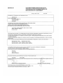
CERAMIC HOB RANGE
ARDOX IC
User Manual
S/N: 055503/04
Rev.: 2.0
7.3.2006
Rev. 2.0
Dear Customer,
Congratulations on deciding to choose our appliance for your kitchen activities. You
made an excellent choice. We will do our best to make you a satisfied customer like thousands of customers we have around the world.
Please read this manual carefully. You will learn correct, safe and efficient working methods in order to get the best possible benefit from the appliance. The instructions and hints
in this manual will give you a quick and easy start, and you will soon note how nice it is
to use our equipment.
All rights are reserved for technical changes.
You will find the main technical data on the rating plate fixed to the equipment. When you
need service or technical help, please let us know the serial number shown on the rating
plate. This will make it easier to provide you with correct service.
For your convenience, space is provided below for you to record your local service contact information.
Service phone number:...............................................................................................
Contact person:....................................................................................................................
7.3.2006
Rev. 2.0
7.3.2006
Rev.
1. General .......................................................................................................... 1
1.1 Symbols used in the manual .......................................................................................... 1
1.2 Symbols used on the appliance ...................................................................................... 1
1.3 Checking the relationship of the appliance and the manual .......................................... 1
2. Safety .............................................................................................................. 3
2.1 Safe use of the appliance ............................................................................................... 3
2.2 Safety instructions in case of malfunction ..................................................................... 3
2.3 Disposal of the appliance ............................................................................................... 3
3. Functional description .................................................................................. 4
3.1 General ..........................................................................................................................
3.2 Application of the appliance ..........................................................................................
3.2.1 Prohibited use .......................................................................................................
3.3 Construction and operating principle ............................................................................
3.3.1 Operating switches and indicator lights .................................................................
4
4
4
4
4
4. Operation instructions ................................................................................. 6
4.1 Before using the appliance ............................................................................................
4.1.1 Selecting cookware for ceramic hobs with infrared heating ..................................
4.1.2 Selecting cookware for ceramic hobs with induction heating ...............................
4.2 Operation procedures .....................................................................................................
4.2.1 Using the range ......................................................................................................
4.3 After use ........................................................................................................................
4.3.1 Cleaning ................................................................................................................
4.3.2 Other service measures ..........................................................................................
6
6
6
7
7
7
7
8
5. Installation ..................................................................................................... 9
5.1 General .......................................................................................................................... 9
5.2 Ambient conditions ....................................................................................................... 9
5.3 Storage, transporting and unpacking the range ............................................................. 9
5.4 Positioning the range ..................................................................................................... 9
5.5 Electrical connections .................................................................................................. 10
5.6 Test-run ........................................................................................................................ 10
6. Troubleshooting ......................................................................................... 11
6.1 Troubleshooting guide ................................................................................................. 12
7.3.2006
Rev.
8. Technical specifications .............................................................................. 23
7.3.2006
Rev. 2.0
General
1. General
Carefully read the instructions in this manual as they contain important information regarding proper, efficient and safe installation, use and maintenance of the appliance.
Keep this manual in a safe place for eventual use by other operators of the appliance.
The installation of this appliance must be carried out in accordance with the manufacturer’s instructions and following local regulations. The connection of the appliance to the
electric and water supply must be carried out by qualified persons only.
Persons using this appliance should be specifically trained in its operation.
Switch off the appliance in case of failure or malfunction. The periodical function checks
requested in the manual must be carried out according to the instructions. Have the appliance serviced by a technically qualified person authorized by the manufacturer and using
original spare parts.
Not complying with the above may put the safety of the appliance in danger.
The manufacturer does not take responsibility for any damages in case the operation instructions and warnings contained in this manual are neglected.
1.1
Symbols used in the manual
This symbol informs about a situation where a safety risk might be at hand. Given instructions are mandatory in order to prevent injury.
This symbol informs about the right way to perform in order to prevent bad results, appliance damage or hazardous situations.
This symbol informs about recommendations and hints that help to get the best performance out of the appliance.
1.2
Symbols used on the appliance
This symbol on a part informs about electrical terminals behind the part. The removal of
the part must be carried out by qualified persons only.
1.3
Checking the relationship of the appliance and the manual
The rating plate of the appliance indicates the serial number of the appliance. If the manuals are missing, it is possible to order new ones from the manufacturer or the local rep-
1
7.3.2006
Rev. 2.0
General
resentative. When ordering new manuals it is essential to quote the serial number shown
on the rating plate.
2
7.3.2006
Rev. 2.0
Safety
2. Safety
2.1 Safe use of the appliance
Because the range is a heated appliance that has hot surfaces during normal use, the following warnings and instructions must be followed in order to avoid burns.
•
•
•
•
•
•
•
•
2.2
During long-time operation even the frame surrounding the ceramic hob gets hot.
The cooking zones are hot for a long time after switching them off, although the
visible heat radiation has ended.
For safe handling of cookware on the cooking top, always use heat protective
gloves.
Do not leave the range on for long periods totally without supervision.
Do not place aluminium foil and plastic vessels on the hot hob surface.
Metallic objects such as kitchen utensils, cutlery etc.shall not be placed on hob surface within induction heating zones as they could get hot.
Take care when operating induction heating surface, as rings, watches and similar
objects worn by user could get hot when in close proximity to the hob surface.
Users with heart pacemakers should consult their doctor whether they are safe near
induction range or not.
Safety instructions in case of malfunction
If the surface of ceramic hob is cracked, immediately disconnect the appliance from the
mains.
2.3
Disposal of the appliance
The destroying of the appliance when its economical lifetime has been reached may be
harmful to environment if not properly handled. Utilization of materials that are reusable
is best done by professional personnel specialized in recycling.
3
7.3.2006
Rev. 2.0
Functional description
3. Functional description
3.1 General
The Ardox IC range is an appliance with two different types of heating systems. Two
cooking zones are heated by induction power source while another two cooking zones are
heated by infrared (radiant) heating elements.
3.2 Application of the appliance
The appliance is intended for preparing various kinds of foodstuffs using cookware. The
range can be used for cooking, keeping warm, flambering, roasting etc.
3.2.1 Prohibited use
Use of the appliance for any other purposes than that of mentioned above is prohibited.
Preparing of food directly on the ceramic hob surface without cookware is prohibited.
3.3 Construction and operating principle
Ceramic hob surface of Ardox IC consists of two hob elements with induction heating
source and two hob elements with infrared heating elements. Cooking zones for each hob
element are marked on glass ceramic surface. Induction cooking zones are marked by
squares. Infrared heating zones are marked by circles.
Cookware placed on ceramic hob surface within induction heating zones is heated up by
means of electromagnetic field generated by induction heating source. Electromagnetic
field influences only the bottom of cookware. Energy transfer stops immediately if cookware is taken away from hob surface and starts again when cookware has been placed
back on hob surface.
Cookware placed on ceramic hob surface within infrared heating zones is heated up by
means of radiant heating elements placed beneath ceramic hob surface.
3.3.1 Operating switches and indicator lights
Each cooking zone is operated by means of stepless power switch. Two power switches
for induction heating zones are located on the left side of control panel, and two power
switches for infrared heating zones are located on the right side of the control panel.
4
7.3.2006
Rev. 2.0
Functional description
Above each power switch, there is a green LED indicator. Steady light of indicator means
that power switch is on and power is transferred to corresponding heating zone.
To generate power for infrared cooking zone, turn the corresponding switch from “0” position to any position between “1” and “6”. The maximum power is when the switch is in
“6” position, and the minimum when in “1” position.
To generate power for induction cooking zone, put first cookware within cooking zone
and turn corresponding switch from “0” position to any position between “1” and “12”.
The maximum power is when the switch is in”12” position, and the minimum power when
the switch is in “1” position.
5
7.3.2006
Rev. 2.0
Operation instructions
4. Operation instructions
4.1
Before using the appliance
4.1.1 Selecting cookware for ceramic hobs with infrared heating
Cookware made of stainless steel, aluminium and enamelled steel is best suitable for
cooking. Enamel based cast iron cookware can also be used if handled with extra care.
Cookware made of copper, ceramic and glass is not fit for use on ceramic hobs with infrared heating.
4.1.2
Selecting cookware for ceramic hobs with induction heating
Cookware made from stainless steel with a compound multilayer base. The magnetic induction base functions as a part of the hob’s magnetic field. Enamelled steel, cast iron and
enamelled cast iron cookware is also suitable for induction hobs.
As a rule, all the cookware suitable for induction hobs can be recognized by the mark “induction” on the base of cookware. If there is no mark on a base, it is recommended to use
a permanent magnet. The magnet must stick to the bottom of cookware.
Diameter of the cookware base has to be at least 120 mm. Cookware with base diameter
less than 120 mm is not detected.
Cookware made of copper, aluminium, ceramic and glass is not suitable for use on ceramic hobs with induction heating.
Cookware made of stainless steel with base which does not attract a permanent magnet is
not suitable for use on ceramic hobs with induction heating.
To get the best benefit from the range as well as from cookware, please observe the following rules:
•
•
•
•
•
•
6
Always lift cookware, do not drag
Use good quality flat-based cookware
Wait for pans to cool before put it in cold water
Always ensure cookware has a clean, dry base before use
Ensure cookware handles are positioned safely and away from heat sources
Always use lids except when frying
7.3.2006
Rev. 2.0
Operation instructions
•
•
Ensure cookware matches the size of cooking zone where possible
Remember good quality cookware retain heat well, so generally, only low or medium heat is necessary
4.2 Operation procedures
4.2.1 Using the range
Ardox IC range with ceramic hobs heats up very fast, so no preheating is necessary.
Infrared cooking zones
Select cooking zone according to cookware to be applied and food to be prepared. Start
cooking from position “6” and when boiling begins, decrease the power as needed. Cookware should be placed on the centre of heating zone, otherwise the bottom is heated unevenly.
Despite the fact that infrared heating elements are equipped with temperature limiters, the
cooking zones should not be left without a pan for a long period. If the set power of cooking zone exceeds the heat reception capability of the pan, the temperature limiter would
adjust the power as needed.
Induction cooking zones
To generate power for induction cooking zone, put first cookware within cooking zone
and turn corresponding switch from “0” position to any position between “1” and “12”.
The maximum power is when the switch is in”12” position and the minimum power when
the switch is in “1” position.
Induction heating zones are also controlled by temperature sensor. Overheated pans (hot
oil, empty pans) can be detected and energy transfer will be stopped. The induction zones
must be restarted after they have cooled down.
If there is a long interruption in the electricity supply,all power switches of the range
should be set to “0” position. This should be done to prevent unexpected start up of the
range when electricity supply is restored.
4.3
After use
4.3.1 Cleaning
Use of water hose or pressure cleaning jet is strictly forbidden.
When cleaning the ceramic hob surface, remember that it is hot for a long time after use.
The cleaning of ceramic hob surface is identical to cleaning of other similar surfaces like
glass. Do not use corrosive or abrasive agents such as grill-and oven-sprays, stain-and rust
removers, scouring powder and rough sponges. Cleaning is much easier if possible spillovers are removed immediately with damp cloth.
7
7.3.2006
Rev. 2.0
Operation instructions
Sugar and mixes containing much sugar must be removed immediately, because later removing is labourious and may leave permanent marks.
Burnt spillovers are easy to remove with a scraper especially intended for cleaning ceramic hob surfaces.
If plastic or aluminium foils melt on the ceramic hob surface, they can be also removed
with the scraper.
When cleaning, always prefer chemical cleaning methods rather than mechanical rubbing.
Use a slightly alkaline detergent (pH 8-10) diluted in water according to instructions when
cleaning the surfaces of the range.
4.3.2 Other service measures
The appliance does not include any user serviceable parts inside. Service must be done by
authorised service personnel only.
8
7.3.2006
Rev. 2.0
Installation
5. Installation
5.1 General
The installation of this appliance must be carried out in accordance with the manufacturer’s instructions and in compliance with local rules and regulations. These instructions
must be used together with the installation drawing.
The connection of the appliance to the electrical and water supply must be carried out by
qualified persons only.
5.2 Ambient conditions
This appliance is intended to be used under the following ambient conditions:
Max.ambient temperature:
Storage
>-20º C...+70º C
Function >+5º C...+40º C
Max. relative humidity of air:
Storage
>10%...90%
Function >30%...90%
5.3 Storage, transporting and unpacking the range
It is recommended to keep appliance in its own package before the actual installation begins. It protects appliance from outer damages. If it is necessary to unpack appliance, possible lifting must be done from the bottom frame using suitable spacers of wood.
In order to avoid damages, it is not allowed to use ceramic hob surface as a workbench
during installation.
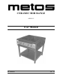
5.4 Positioning the range
Because the temperature of infrared cooking zones accidentally forgotten on without a
pan may reach even 550º C, it is mandatory to follow local fire safety regulations when
installing the range.
9
7.3.2006
Rev. 2.0
Installation
This appliance is equipped with its own internal cooling system. Air inlet is located on
the bottom of the stainless steel enclosure. Temperature of intake air should be below 40º
C. This appliance can not be placed direct near ovens or other heating appliances where
ambient temperature may reach over 40ºC.
When the range is in the right place, it must be levelled in horizontal position by turning
adjustable legs. After that, the rear legs must be fixed to the floor by means of flanges and
anchor bolts (see installation drawing).
5.5 Electrical connections
Check and ensure that supply voltage is the same as the voltage given on the rating plate
of the appliance. The electrical connections must satisfy local house installation regulations. The valid national and local regulations of the electricity supply inspection must be
observed.
In order to make future servicing easier and increase safety, a mains switch must be installed near the appliance. This switch must disconnect the appliance completely from an
electrical supply network.
The feed-through for the supply cable is located at the bottom of the range in the right
front corner. To connect the supply cable to the terminal, do the following:
•
•
•
•
•
Remove two screws which fix control panel and stainless steel enclosure
Open ceramic hob and fix it by the fixing rod. The fixing rod is on the left side inside the enclosure
Pull control panel out approx. 200...250 mm
Connect supply cable to the terminal. The terminal is on the right side inside enclosure
To assemble appliance, carry out operations described above in opposite order
Before close the ceramic hob, check that no wires inside the range get jammed.
5.6
Test-run
Please read the user manual before testing the appliance. After connecting the supply cable, check the function of the range.
Check that:
•
•
10
Infrared cooking zones heat up and corresponding green LED illuminates after the
power switch has been turned to ON position
Induction cooking zones heat up after cookware has been placed onto cooking
zone and the power switch turned to ON position.
7.3.2006
Rev. 2.0
Troubleshooting
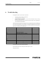
6. Troubleshooting
If the appliance fails to work, check to ensure that
•
•
•
•
it has been used according to instructions
all removable parts are in place
the disconnection switch (usually on a wall or in the immediate vicinity of the appliance) is in the ON position
the circuit breakers (fuses) have not blown on the fuse board. Ask a qualified person to check the circuit breakers.
Abnormal function of induction heating unit can be recognised by means of flashing signals of green LED indicator (error messages). The indicator lamp flashes with an interval
of 0,6 sec. The number of short flashes has to be counted. Information on the kind of possible errors you may find in the table below.
Number of Flashes
Possible Error
Remarks
Steady light
01
02
03
04
05
06
07
08
09
10
11
12
13
14
No fault, normal operation
No coil current, hardware overcurrent
High coil current, software overcurrent
Cooling plate temperature
Cooking plate temperature, overheating
Power switch line break
Excessive inside temperature
Sensing element of cooking platform, short circuit
3)
3)
1)
1)
1)
2)
1)
Power reduction cooling plate temperature
Power reduction cooking platform temperature
Power reduction caused by bad pan material
2)
2)
2)
1)The induction unit stops working immediately.
2)The induction unit is still working with reduced power cycles.
3)Bad pan material
11
7.3.2006
Rev. 2.0
Troubleshooting
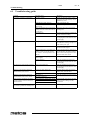
6.1 Troubleshooting guide
Problem
No heating, indicator is OFF(dark)
Possible Cause
no mains supply
control knob in OFF position
pan too small (bottom diameter less
than 12 cm)
pan is not placed in the centre of the
heating area (the cooker does not detect the pan)
unsuitable pan
cooker defective
Poor heating, indicator is ON (shines)
used pan is not ideal
air-cooling system obstructed
ambient temperature is too high (the
cooling system is not able to keep
the cooker in normal operation conditions)
one phase is missing (only with 3phase supply)
cooker defective
No reaction to control knob positions
power switch defective
Heating cycle switches off and on
within minutes, fan is active
air inlet or outlet obstructed
Heating cycle switches off and on
within minutes, fan is never active
After a longer permanent operating
time the heating switches off and on
within minutes
Small metallic objects (e.g. spoon)
are heated up within the cooking area
12
grease filter is dirty
fan defective
fan control defective
coil overheated, cooking area too hot
empty pan
pan with overheated oil
pan detection tuned incorrectly
Measures
check the electrical supply (cable
plugged in the wall socket), check
preliminary fuses
turn control knob ON
use a suitable pan
move the pan to the centre of the
heating area
choose a pan which is recommended for induction cooking
ask your supplier for repair service,unplug the cooker from an electrical supply
use a pan which is recommended
for induction cooking, compare results wuth “your” pan
verify that air inlet air outlet are not
obstructed with objects
verify that no hot air is sucked in by
the fan.Reduce the ambient temperature.The air inlet temperature must
be lower than 40ºC/110ºF
check preliminary fuses
ask your supplier for repair service,unplug the cooker from an electrical supply
ask your supplier for repair service,unplug the cooker from an electrical supply
remove objects from air inlet and
outlet slots, clean the slots
clean grease filter
ask your supplier for repair service
switch cooker off, remove pan and
wait until the cooking area has
cooled off
control logic board
7.3.2006
Rev. 2.0
Technical specifications
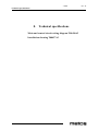
8.
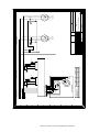
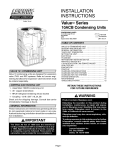
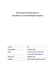
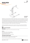
Technical specifications
Main and control circuit wiring diagram T00436A3
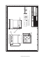
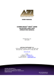
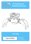
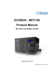
Installation drawing T00437A3
23
Main and control circuit wiring diagram T00436A3
)
(
'
&
%
$
/
/
/
1
3(
/ /
/
6
9(5..2(/(&75,&6833/<
13($&9+]
9+]3+$6(6N:
7(50267$7
32:(5
3/$7)250
3(
13($&9+]
/
3
3N:
5$',$17
7(50267$7
3
6
,$
6
02'8
3N:
+9
32:(5
3/$7)250
5.20
,1'8&7,210RGXO/LQH02'8
,$
3
/
3
6
5.20
+9
6WDWH
/&6
9
7
&KDQJHV
9
9
)
$
'DWH
6
1DPH
3
3
)LOHQDPH
9%
1DPH
6XUIDFH
6?9DOHUL?,QGXFWLRQUDQJH?7$GZJ
&RGH
6WDQGDUG
&KHFNHG
'DWH
(
N:9
+
'UDZQ
6
6
5$',$17+($7,1*02'8/
$UGR[,&
6
3RVLWLRQ
6
6
7$
3
4XDQWLW\
(
N:9
+
3
0DLQDQGFRQWUROFLUFXLWZLULQJGLDJUDP
6FDOH
3DJH
3J
)
(
'
&
%
$
Installation drawing T00437A3
)
(
'
&
%
$
$UGR[,&
3N:
5$',$17
,$
3N:
6WDWH
&KDQJHV
'DWH
1DPH
'DWH
)LOHQDPH
1DPH
9%
8?,QGXFWLRQUDQJH?$UGR[,?7$GZJ
&RGH
6WDQGDUG
&KHFNHG
'UDZQ
6XUIDFH
3RVLWLRQ
7$
,QVWDOODWLRQGUDZLQJ
5DQJH$UGR[,&
6FDOH
7+(5(48,0(176*,9(1,1,167$//$7,21,16758&7,2160867$/62%()2//2:('
&211(&7,2132,17)25(;7(51$/&$%/()5200$,16
7+(%$&.)((76+28/'%(),;('
13($&9+]
(/(&75,&$/6833/<
4XDQWLW\
,$
,1'8&7,21
3DJH
3J
)
(
'
&
%
$
7.3.2006
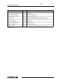
Technical specifications
Item
Model Specification
Outer dimensions WxDxH
Ardox IC 802x802x900 mm
Ceramic cooking hob dimensions WxD Ardox IC 650x650 mm
Cooking zone 2pcs. infrared
Ardox IC 2500W, ø230 mm each
Cooking zone 2pcs. induction
Ardox IC 3500W, 270x270 mm each
Power regulation
Ardox IC Stepless energy regulator, indicator lamp for each zone
Material
Ardox IC Ceramic cooking hob. All other surfaces of stainless steel
Weight with package
Ardox IC Appr. 95 kg
Weight without package
Ardox IC Appr. 60kg
Package dimensions WxDxH
Ardox IC 860x920x1050 mm
Electrical connection
Ardox IC See installation drawing
Operating conditions
Ardox IC >+5...40°C, Max.relative humidity of air >30%...90%
IC=ARDOX IC
26
Rev. 2.0