1
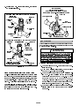
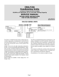
INSTALLATION INSTRUCTIONS £ PRODUCT LITERATURE ¤ 1998 Lennox Industries Inc. 9DOXH70 6HULHV Dallas, Texas $&% &RQGHQVLQJ 8QLWV &21'(16,1* 81,76 1--1/2 through 5 ton 503,800M 2/98 /LWKR 86$ Supersedes 503,755M TABLE OF CONTENTS VALUE 10TM CONDENSING UNIT Value 10 condensing units are designed for expansion valve (TXV) and RFC systems. Refer to Lennox engineering handbook for expansion valve kits which must be ordered separately. SHIPPING AND PACKING LIST VALUE 10 CONDENSING UNIT . . . . . . . . . . . . . . . . . . . . . 1 SHIPPING AND PACKING LIST . . . . . . . . . . . . . . . . . . . . . . 1 GENERAL INFORMATION . . . . . . . . . . . . . . . . . . . . . . . . . . 1 10ACB UNIT DIMENSIONS . . . . . . . . . . . . . . . . . . . . . . . . . 2 SETTING THE UNIT . . . . . . . . . . . . . . . . . . . . . . . . . . . . . . . . 3 ELECTRICAL . . . . . . . . . . . . . . . . . . . . . . . . . . . . . . . . . . . . . . 3 PLUMBING . . . . . . . . . . . . . . . . . . . . . . . . . . . . . . . . . . . . . . . 4 REFRIGERANT METERING DEVICE . . . . . . . . . . . . . . . . . . 4 MANIFOLD GAUGE SET . . . . . . . . . . . . . . . . . . . . . . . . . . . 5 LIQUID & SUCTION LINE SERVICE VALVES . . . . . . . . . . 5 LEAK TESTING . . . . . . . . . . . . . . . . . . . . . . . . . . . . . . . . . . . . 6 EVACUATION . . . . . . . . . . . . . . . . . . . . . . . . . . . . . . . . . . . . . 7 START-UP . . . . . . . . . . . . . . . . . . . . . . . . . . . . . . . . . . . . . . . . 8 CHARGING CONSIDERATIONS . . . . . . . . . . . . . . . . . . . . . 8 CHARGING FOR RFC SYSTEMS . . . . . . . . . . . . . . . . . . . . 9 CHARGING FOR TXV SYSTEMS . . . . . . . . . . . . . . . . . . . 10 SYSTEM OPERATION . . . . . . . . . . . . . . . . . . . . . . . . . . . . . 10 MAINTENANCE . . . . . . . . . . . . . . . . . . . . . . . . . . . . . . . . . . 11 10ACB CHECK POINTS . . . . . . . . . . . . . . . . . . . . . . . . . . . . 12 RETAIN THESE INSTRUCTIONS FOR FUTURE REFERENCE 1-- Assembled 10ACB condensing unit 1-- 45E copper street elbow 1-- RFCIV refrigerant metering device (bullet) WARNING 1-- Coupling -- 5/16 x 3/8 (18, 24, 30) Check unit for shipping damage. Consult last carrier immediately if damage is found. Product contains fiberglass wool. Disturbing the insulation in this product during GENERAL INFORMATION installation, maintenance, or repair will expose These instructions are intended as a general guide and do not supersede national or local codes in any way. Authorities having jurisdiction should be consulted before installation. you to fiberglass wool. Breathing this may cause lung cancer. (Fiberglass wool is known to the State of California to cause cancer.) Fiberglass wool may also cause respiratory, skin, and eye irritation. IMPORTANT To reduce exposure to this substance or for further information, consult material safety data sheets available from address shown below, or contact The Clean Air Act of 1990 bans the intentional your supervisor. venting of refrigerant (CFCs and HCFCs) as of July 1, 1992. Approved methods of recovery, recycling Lennox Industries Inc. or reclaiming must be followed. Fines and/or in- P.O. Box 799900 carceration may be levied for non--compliance. Dallas, TX 75379--9900 3DJH 10ACB UNIT DIMENSIONS--INCHES (MM) INLET AIR INLET INLET AIR AIR INLET SUCTION LINE CONNECTION LIQUID LINE CONNECTION AIR TOP VIEW 24-1/4 (616) 24-1/4 (616) DISCHARGE OUTDOOR COIL FAN AIR COMPRESSOR B A SUCTION & LIQUID LINE CONNECTION ELECTRICAL INLETS 2-3/4 (70) 3/4 (19) SIDE VIEW SIDE VIEW Model No. 10ACB12 in. A B 25 24-1/4 635 616 33 32-1/4 838 819 10ACB18 10ACB24 10ACB30 10ACB36 10ACB42 mm in. 10ACB48 10ACB60 10ACB62 mm 3DJH SETTING THE UNIT Roof Mounting Install unit at a minimum of 4 inches above the surface Refer to unit dimensions on page 2 for sizing mounting of the roof. Care must be taken to ensure weight of unit slab, platforms or supports. Refer to figure 1 for instal- is properly distributed over roof joists and rafters. Ei- lation clearances. ther redwood or steel supports are recommended. ELECTRICAL In the U.S.A., wiring must conform with current local INSTALLATION CLEARANCES codes and the current National Electric Code (NEC). In Canada, wiring must conform with current local codes and the current Canadian Electrical Code (CEC). Refer to 36 (914 mm) the furnace or blower coil installation instructions for additional wiring application diagrams and refer to unit rating plate for minimum circuit ampacity and maximum overcurrent protection size. 36 *36 (914 mm) (914 mm) WARNING Unit must be grounded in accordance with national and local codes. Electric Shock Hazard. Can cause injury or death. *36 (914 mm) Line Voltage To facilitate conduit, a hole is provided in bottom of the NOTE48 inch clearance required on top of unit. *NOTEOne side must be 36 inches. Two side may be 12. control box. Connect conduit to hole in control box with proper conduit fitting. FIGURE 1 127( 8QLWV DUH DSSURYHG IRU XVH ZLWK FRSSHU FRQGXF WRUV RQO\ Slab Mounting 24V, Class II Circuit 24V, Class II Circuit connections are made up in the low When installing unit at grade level, install on a level voltage junction box. Refer to figure 2 for field wiring slab high enough above grade to allow adequate drain- diagram. age of water. NOTE -- A complete unit wiring diagram is located in- Top of slab should be located so run--off side the unit control box cover. water from higher ground will not collect around unit. 10ACB TYPICAL FIELD WIRING DIAGRAM NOTE--SEE UNIT WIRING DIAGRAM 24V CLASS II INSTALLED AT FACTORY FOR POWER SUPPLY CONNECTIONS. ROOM THERMOSTAT 24V CLASS II FIELD INSTALLED CONDENSING UNIT TYPICAL INDOOR UNIT C Y1 G W RH RC TRANSFORMER R W1 G TO HEATING CONTROLS W2 Y1 C C TO 24V CLASS II POWER SOURCE -- 20 VA MINIMUM NOTE--IF INDOOR UNIT IS NOT EQUIPPED WITH 24V CLASS II JUNCTION BOX BLOWER RELAY, IT MUST BE FIELD PROVIDED AND INSTALLED (P--8--3251 OR EQUIVALENT) K3 INDOOR BLOWER RELAY FIGURE 2 3DJH 24v TO COOLING SPEED TO HEATING SPEED POWER T1 GROUND PER NATIONAL AND LOCAL CODES PLUMBING NOTE -- Line length should be no greater than 50 feet (15.2 m). Select line set diameters from table 1 to en- Field refrigerant piping consists of liquid and suction lines from the condensing unit (sweat connections) to the indoor evaporator coil (flare or sweat connections). sure oil return to compressor. RFC Systems Use Lennox L10 (flare) or L15 (sweat, non-flare) series line sets as shown in table 1 or use field-fabricated re- 10ACB units are shipped with an RFCIV metering de- frigerant lines. Refer to unit information manual piping vice. Replace existing RFCIV in indoor unit with RFCIV section for proper size, type and application of field-- supplied with the outdoor unit. Place the supplied fabricated lines. RFCIV sticker on indoor cabinet after installation. See table 2 for size of RFCIV bullet shipped in each 10ACB Sweat Connection Procedure unit. In cases of non-traditional applications, RFCIV bullet shipped may not be appropriate. Refer to the in- 1-- Ends of refrigerant lines must be cut square, free from nicks or dents, deburred. Pipe must remain door coil installation instructions and the engineering handbook for specific orifice information. round, do not pinch end of line. 7$%/( 5)&,9 '5,// 6,=(6 2-- Wrap a wet cloth around the liquid line valve body and copper tube stub to protect from heat damage 10ACB UNIT RFCIV PART # RFCIV DRILL SIZE 10ACB12 42J35 0.047 3-- Quench the joints with a wet cloth to prevent possible 10ACB18 42J39 0.055 heat damage to the valve core and opening port. 10ACB24 66J87 0.062 4-- A field provided filter drier should be installed as 10ACB30 42J45 0.067 10ACB36 42J48 0.073 10ACB42 42J52 0.080 10ACB48 42J54 0.084 10ACB60 42J58 0.092 during brazing. Wrap another wet cloth underneath the liquid valve to protect the base paint. close as possible to the expansion device. REFRIGERANT METERING DEVICE 10ACB units are applicable to either RFCIV or an expansion valve system. See indoor coil installation instructions and the Lennox engineering handbook for approved RFC and TXV match-ups and application information. Table 1 lists 10ACB unit liquid and suction RFCIV bullet is installed as shown in figure 3. Take care not to twist cap tubes when loosening seal nut from orifice body. line sizes and corresponding line sets. RFCIV INSTALLATION TABLE 1 REFRIGERANT LINE KITS UNIT LIQUID LINE SUCTION LINE 10ACB18 5/16 in* 5/8 in 10ACB24 (8 mm) (16 mm) 10ACB30 3/8 in 3/4 in. 10ACB36 (10 mm) (19 mm) 10ACB42 3/8 in 7/8 in. 10ACB48 (10 mm) (22 mm) L10 LINE SETS L15 LINE SETS L10--21 L15--21 20 ft. -- 50 ft. 20 ft. -- 50 ft. (6 m -- 15 m) (6 m -- 15 m) L10--41 L15--41 20 ft. -- 50 ft. 20 ft. -- 50 ft. (6 m -- 15 m) (6 m -- 15 m) ORIFICE BODY DISTRIBUTOR BULLET ORIFICE L10--65 L15--65 30 ft. -- 50 ft. 30 ft. -- 50 ft. SEAL (9 m -- 15 m) (9 m -- 15 m) NUT 10ACB60 3/8 in 1--1/8 in. FIELD FIELD 10ACB62 (10 mm) (29 mm) FABRICATED FABRICATED *Use reducer supplied in bag assembly. FIGURE 3 3DJH SWEAT CONNECTION Expansion Valve Systems '$1*(5 Expansion valves equipped with either Chatleff or Do not attempt to backseat this valve. Attempts to flare type fittings are available from Lennox. Refer to backseat this valve will cause snap ring to explode the indoor coil installation instructions or the engineer- from valve body under pressure of refrigerant. ing handbook for applicable expansion valves for use Personal injury and unit damage will result. with specific match--ups. If an expansion valve application is desired with indoor coil product shipped with an RFCIV orifice, the RFCIV re- 3-- Replace stem cap tighten firmly. Tighten finger tight, then tighten an additional 1/6 turn. strictor must be removed before installing the expan- LIQUID LINE SERVICE VALVE (VALVE OPEN) sion valve. INSERT HEX IMPORTANT STEM CAP WRENCH HERE SERVICE PORT Failure to remove RFCIV when installing an expansion valve to the indoor coil will result in improper TO OUTDOOR operation and damage to the system. COIL 0$1,)2/' *$8*( 6(7 A manifold gauge set equipped with low loss hoses SERVICE should be used when checking unit charge. A manifold PORT gauge set with anything other than low loss hose CAP should not be used. TO INDOOR COIL SCHRADER VALVE LIQUID LINE SERVICE VALVE (VALVE CLOSED) /,48,' 68&7,21 /,1( 6(59,&( 9$/9(6 RETAINING RING The liquid line and suction line service valves (figures 4 STEM CAP SERVICE and 5) and gauge ports are accessible from outside the PORT unit. The service ports are used for leak testing, evaINSERT HEX cuating, charging and checking charge. WRENCH HERE TO OUTDOOR The valve is equipped with a service port. A schrader COIL valve is factory installed. A service port cap is supplied to protect the schrader valve from contamination and serve as the primary leak seal. To Access Schrader Port: SERVICE PORT CAP TO INDOOR 1-- Remove service port cap with an adjustable wrench. COIL SCHRADER VALVE OPEN 2-- Connect gauge to the service port. TO LINE SET WHEN VALVE IS CLOSED (FRONT SEATED) 3-- When testing is completed, replace service port cap. Tighten finger tight, then an additional 1/6 turn. (VALVE FRONT SEATED) FIGURE 4 To Open Liquid or Suction Line Service Valve: To Close Liquid or Suction Line Service Valve: 1-- Remove stem cap with an adjustable wrench. 1-- Remove stem cap with an adjustable wrench. 2-- Using service wrench and 5/16 hex head extension 2-- Using service wrench and 5/16 hex head exten- back the stem out counterclockwise until the valve sion, turn stem clockwise to seat the valve. Tighten stem just touches the retaining ring. firmly. 3DJH 3-- Replace stem cap. Tighten finger tight, then tighten SUCTION LINE (BALL TYPE) SERVICE VALVE an additional 1/6 turn. (VALVE OPEN) USE ADJUSTABLE WRENCH ROTATE STEM CLOCKWISE 90E TO CLOSE ROTATE STEM COUNTER-CLOCKWISE 90E TO OPEN SUCTION LINE SERVICE VALVE (VALVE OPEN) STEM CAP INSERT HEX TO OUTDOOR COIL STEM CAP WRENCH HERE TO INDOOR STEM COIL BALL (SHOWN OPEN) TO INDOOR COIL SCHRADER VALVE TO OUTDOOR COIL SERVICE PORT CAP SERVICE PORT SERVICE PORT CAP SCHRADER VALVE SERVICE PORT FIGURE 6 SUCTION LINE SERVICE VALVE (VALVE CLOSED) TO INDOOR RETAINING RING /($. 7(67,1* STEM CAP After the line set has been connected to the indoor and COIL outdoor units, the line set connections and indoor unit must be checked for leaks. INSERT HEX WARNING WRENCH HERE SERVICE PORT Never use oxygen to pressurize refrigeration or air (VALVE FRONT conditioning system. Oxygen will explode on con- SEATED) tact with oil and could cause personal injury. When using high pressure gas such as nitrogen or CO2 for this purpose, be sure to use a regulator that can SERVICE PORT CAP control the pressure down to 1 or 2 psig. SCHRADER VALVE OPEN TO LINE SET WHEN VALVE IS TO OUTDOOR CLOSED (FRONT SEATED) COIL Using an Electronic Leak Detector or Halide 1-- Connect cylinder of HCFC-22 to center port of man- FIGURE 5 ifold gauge set. 2-- With both manifold valves closed, open the valve on the HCFC-22 bottle (vapor only). 5--Ton Suction Line (Ball Type) Service Valve 3-- Open the high pressure side of the manifold to al- A ball-type full service valve only is used on five ton units low HCFC-22 into the line set and indoor unit. (10ACB60/62). These suction line service valves function Weigh in a trace amount of HCFC-22. (A trace the same way, differences are in construction. Valves are amount is a maximum of not rebuildable. If a valve has failed it must be re- pressure.) Close the valve on the HCFC-22 bottle placed. A ball valve valve is illustrated in figure 6. and the valve on the high pressure side of the man- The ball valve is equipped with a service port. A ifold gauge set. Disconnect HCFC-22 bottle. 2 ounces or 3 pounds schrader valve is factory installed. A service port cap 4-- Connect a cylinder of nitrogen with a pressure reg- is supplied to protect the schrader valve from con- ulating valve to the center port of the manifold tamination and assure a leak free seal. gauge set. 3DJH 5 -- Connect the high pressure hose of the manifold tal actual pressure within a given volume or sys- gauge set to the service port of the suction valve. tem, above the absolute zero of pressure. Absolute (Normally, the high pressure hose is connected to pressure in a vacuum is equal to atmospheric pres- the liquid line port, however, connecting it to the sure minus vacuum pressure. suction port better protects the manifold gauge set 5-- When the absolute pressure reaches 23mm of mer- from high pressure damage.) cury, close the manifold gauge valves, turn off the 6-- Adjust nitrogen pressure to 150 psig. Open the vacuum pump and disconnect the manifold gauge valve on the high side of the manifold gauge set center port hose from vacuum pump. Attach the which will pressurize line set and indoor unit. manifold center port hose to a nitrogen cylinder with pressure regulator set to 150 psig and purge 7-- After a short period of time, open a refrigerant port the hose. Open the manifold gauge valves to break to make sure the refrigerant added is adequate to be the vacuum in the line set and indoor unit. Close detected. (Amounts of refrigerant will vary with line the manifold gauge valves. lengths.) Check all joints for leaks. Purge nitrogen &$87,21 and HCFC-22 mixture. Correct any leaks and recheck. Danger of Equipment Damage. Avoid deep vacuum operation. Do not use com- (9$&8$7,1* pressors to evacuate a system. Evacuating the system of non--condensables is critical Extremely low vacuums can cause internal arcing for proper operation of the unit. Non--condensables are and compressor failure. defined as any gas that will not condense under temper- Damage caused by deep vacuum operation will void warranty. atures and pressures present during operation of an air conditioning system. Non--condensables and water va- 6-- Shut off the nitrogen cylinder and remove the man- por combine with refrigerant to produce substances ifold gauge hose from the cylinder. Open the man- that corrode copper piping and compressor parts. ifold gauge valves to release the nitrogen from the line set and indoor unit. 1-- Connect manifold gauge set to the service valve ports as follows: low pressure gauge to suction 7-- Reconnect the manifold gauge to the vacuum line service valve; high pressure gauge to liquid pump, turn the pump on and continue to evacuate line service valve. the line set and indoor unit until the absolute pressure does not rise above .5mm of mercury within a 2-- Connect the vacuum pump (with vacuum gauge) 20 minute period after shutting off the vacuum to the center port of the manifold gauge set. 3-- Open both manifold valves and start vacuum pump. pump and closing the manifold gauge valves. 8-- Depending on the equipment used to determine the vacuum level, the following units are equiva- 4-- Evacuate the line set and indoor unit to an absolute lent to absolute pressure of .5mm of mercury or pressure of 23mm of mercury or approximately 1 inch of mercury. During the early stages of evacuation, it is desirable to close the manifold gauge 500 microns. 9-- When the absolute pressure requirement above has valve at least once to determine if there is a rapid rise in absolute pressure. A rapid rise in pressure indicates a relatively large leak. If this occurs, the leak testing procedure must be repeated. NOTE -- The term been met, disconnect the manifold hose from the vacuum pump and connect it to an upright bottle of HCFC-22 refrigerant. Open the manifold gauge valves to break the vacuum in the line set and indoor unit. Close manifold gauge valves and shut off absolute pressure means the to- 3DJH HCFC-22 bottle and remove manifold gauge set. TABLE 3 67$5783 IMPORTANT Crankcase heater (used on 3--1/2, 4 and 5 ton units) should be energized 24 hours before unit Liquid Line Ozs. per 5 ft. (ml per mm) adjust Set Diameter from 20 ft. (6.1m) line set* 5/16 in. (8mm) 2 ounce per 5 ft. 3/8 in. 3 ounce per 5 ft. (10mm) (85ml per 1.5m) (57ml per 1.5m) *If line length is greater than 20 ft. (6.1m), add this amount. If start--up to prevent compressor damage as a re- line length is less than 20 ft. (6.1m), subtract this amount. sult of slugging. 1-- Rotate fan to check for frozen bearings or binding. 2-- Inspect all factory and field-installed wiring for If the system is void of refrigerant, the recommended and most accurate method of charging is to weigh the loose connections. 3-- After evacuation is complete, open liquid line and suction line service valves to release refrigerant charge (contained in condensing unit) into the sys- refrigerant into the unit according to the total amount shown on the unit nameplate. This may be done after any leaks have been repaired. If weighing facilities are not available or if unit is just low on charge, use one of tem. 4-- Replace stem caps and secure finger tight, then tighten an additional (1/6) one-sixth of a turn. the procedures outlined. Charging a condensing unit is recommended during 5-- Check voltage supply at the disconnect switch. The warm weather. However, applications arise in which nameplate. If not, do not start the equipment until The way the unit is charged depends on the units refrigerant me- the power company has been consulted and the tering voltage must be within the range listed on unit voltage condition corrected. 6-- Set the thermostat for cooling demand, turn on power to evaporator blower and close condensing unit disconnect switch to start unit. 7-- Recheck voltage with unit running. Power must be within range shown on nameplate. Check amperage draw of unit. Refer to unit nameplate for cor- charging must occur in the colder months. device and the outdoor ambient temperature. For RFC systems, weighing in the charge and subcooling are two acceptable means of charging under certain conditions. For installations of an RFC system where the outdoor ambient is less than 65EF (18EC), weighing in the charge is the best method. However, in installations where the outdoor ambient is 65EF (18EC) or above, subcooling is the best method. rect running amps. Weighing in the charge and the approach method are &+$5*,1* &216,'(5$7,216 the two recommended procedures for charging the 10ACB using an expansion valve system for refrigerant Units are factory charged with the amount of HCFC-22 metering. The difference between the two involves the refrigerant indicated on the unit rating plate. This outdoor ambient temperature. For expansion valve charge is based on a matching indoor coil and outdoor systems where the outdoor ambient temperature is coil with 20 ft. (6.1m) line set. For varying lengths of line 60EF (16EC) or above, the approach method may be set, refer to table 3 for refrigerant charge adjustment. A used. For expansion valve systems where the outdoor blank space is provided on the rating plate to list the ac- ambient temperature is below 60EF (16EC), weighing in tual field charge. the charge is recommended. 3DJH TABLE 4 NORMAL OPERATING PRESSURES IN PSIG (LIQUID AND SUCTION +/-- 10 PSIG)* OUT. COIL MODE ENTERING AIR TEMP. TXV 10ACB18 10ACB24 10ACB30 10ACB36 10ACB42 10ACB48 10ACB60 10ACB62 LIQ. SUC. LIQ. SUC. LIQ. SUC. LIQ. SUC. LIQ. SUC. LIQ. SUC. LIQ. SUC. LIQ. SUC. LIQ. SUC. 65 (18.3) 145 71 155 65 160 65 168 63 176 62 162 68 157 69 153 66 159 64 75 (23.9) 167 77 181 70 188 70 197 68 203 66 185 72 182 72 180 71 188 68 85 (29.4) 192 81 208 75 216 74 227 73 233 70 210 73 204 73 210 74 219 72 95 (35.0) 221 84 238 80 247 78 258 77 266 74 252 76 244 76 245 77 253 75 105 (40.6) 253 87 270 84 280 82 292 80 299 77 287 79 278 79 279 79 287 76 65 (18.3) 140 79 159 73 164 71 173 71 179 68 157 71 158 70 142 73 151 69 75 (23.9) 161 80 183 75 189 73 199 73 205 70 187 73 182 72 168 75 179 71 85 (29.4) 189 81 209 77 217 75 228 75 235 72 217 74 205 73 202 76 211 73 95 (35.0) 220 83 238 80 247 78 258 77 266 74 255 76 246 76 245 77 249 74 105 (40.6) 254 84 269 82 279 80 292 79 299 77 289 77 280 79 280 78 286 75 qF (qC) RFCIV 10ACB12 *These are typical pressures only. Indoor evaporator match up, indoor air quality and evaporator load will cause the pressures to vary. 4 -- When IMPORTANT thermostat demand has been satisfied, switch to cooling mode with a set point of 68EF (20EC). When pressures have stabilized, record the Use table 4 as a general guide for performing main- liquid line temperature. tenance checks. Table 4 is not a procedure for in these 5 -- The outdoor temperature will determine which pressures may be expected due to differences in charging method to use. Proceed with the ap- charging the system. Minor variations installations. Significant deviations could mean propriate charging procedure below. that the system is not properly charged or that a problem exists with some component in the system. Used prudently, table 4 could serve as a useful &+$5*,1* )25 5)& 6<67(06 service guide. Weighing in the Charge Method E E RFC Systems, < 65 F (18 C) Outdoor Temp Before charging the unit, follow the procedure below 1-- Recover the refrigerant from the unit. to determine: the liquid line temperature and the out- 2-- Conduct a leak check, then evacuate as previously door ambient temperature. outlined. 3-- Weigh in the factory charge as shown on the out- 1 -- Connect manifold gauge set to service valves: low pressure gauge to suction valve service port; high pressure gauge to liquid valve service port. Connect the center manifold hose to an upright bottle of HCFC-22. Close manifold gauge set valves. door units rating plate. The Subcooling Method E E RFC Systems, > 65 F (18 C) Outdoor Temp 1-- With the manifold gauge hose still on the liquid service port and the unit operating stably, record the 2 -- Set the room thermostat to call for heat. This will create the necessary load for properly charging the liquid line temperature. 2-- At the same time, record the liquid line pressure system in the cooling cycle. reading. 3 -- Record the outdoor ambient temperature. For 3-- Using a temperature/pressure chart for HCFC-22, greater accuracy, use the same electronic ther- determine the saturation temperature for the liquid mometer to measure liquid temperature. line pressure reading. 3DJH 4-- Subtract the liquid line temperature from the satu- agree with the values given in table 6. If not, add refrig- ration temperature (according to the chart) to de- erant to lower the approach temperature or recover re- termine subcooling. (Saturation temperature -- frigerant from the system to increase the approach Liquid line temperature = Subcooling) temperature. TABLE 6 5-- Compare the subcooling value with those in table APPROACH METHOD 5. If subcooling is greater than shown, some refrigNO. shown, some refrigerant must be added. TABLE 5 SUBCOOLING FOR RFC SYSTEMS LIQUID SUBCOOLING [+ 1EF (.6EC)] OUTDOOR 012 018 024 030 036 042 048 LIQUID LINE -- OUTDOOR AMBIENT 10ACB12 7 (3.9) 10ACB18 5 (2.8) 10ACB24 9 (5) 060 10ACB30 10 (5.6) 10ACB36 12 (6.7) 10ACB42 14 (8) 10ACB48 13 (7.2) TEMP. EF (EC) APPROACH TEMPERATURE MODEL erant must be recovered. If subcooling is less than 60 14 17 18 18 14 14 12 14 (16) (7.8) (9.5) (10) (10) (8) (8) (6.7) (8) 65 13 16 16 17 13 13 11 14 (18) (7.2) (8.9) (8.9) (9.5) (7.8) (7.8) (6.1) (8) 70 12 15 14 16 12 13 10 13 (21) (6.7) (8.3) (7.8) (8.9) (6.7) (7.8) (5.6) (7.8) 10ACB60 12 (6.7) 10ACB62 12 (6.7) 75 10 14 12 15 10 12 9 13 (24) (5.6) (7.8) (6.7) (8.3) (5.6) (6.7) (5) (7.8) Note -- For best results, the same electronic thermometer should be 80 9 13 11 14 9 11 9 12 (27) (5) (7.2) (6.1) (8) (5) (6.1) (5) (6.7) 85 8 12 10 13 8 10 9 12 (29) (4.5) (6.7) (5.6) (7.8) (4.4) (5.6) (5) (6.7) 90 7 11 9 12 7 10 8 12 (32) (3.9) (6.1) (5) (6.7) (3.9) (5.6) (4.5) (6.7) 95 6 9 8 11 6 9 8 12 (35) (3.3) (5) (4.5) (6.1) (3.3) (5) (4.5) (6.7) 100 4 8 7 10 5 9 8 11 (38) (2.2) (4.5) (3.9) (5.6) (2.8) (5) (4.5) (6.1) 105 2 7 6 9 4 9 7 10 (1.1) (3.9) (3.3) (5) (2.2) (5) (3.9) (5.6) 6<67(0 23(5$7,21 Condensing unit and indoor blower cycle on demand room thermostat. When thermostat blower switch is switched to ON position, indoor blower operates continuously. Crankcase Heater 110 2 6 6 7 3 8 7 9 (43) (1.1) (3.3) (3.3) (3.9) (1.7) (4.5) (3.9) (5) 115 1 5 5 5 2 7 6 8 (45) (0.6) (2.8) (2.8) (2.8) (1.1) (3.9) (3.3) (4.5) Three and one-half, four and five ton units are equipped Note -- For best results, the same electronic thermometer should be with internal self-regulating crankcase heaters. Compressor Start Kit Three and one-half, four and five ton single-phase units used to check both outdoor ambient and liquid temperatures. have internal start components and do not require field &+$5*,1* )25 7;9 6<67(06 E used to check both outdoor ambient and liquid temperatures. from (41) Weighing in the Charge EF (EC) installation of a compressor start kit. Timed-Off Control (Option Units ONLY) Option units are factory-equipped with a timed-off E TXV Systems, < 60 F (16 C) Outdoor Temp control which helps equalize system pressures that allows the compressor to start in an unloaded condition 1-- Recover the refrigerant from the unit. 2-- Conduct a leak check, then evacuate as previously outlined. as well as preventing compressor short-cycling. The timed-off control delays compressor start-up for five minutes on thermostat demand. Mounted in the con- 3-- Weigh in the factory charge as shown on the outdoor units rating plate. The Approach Method E trol box, the control is wired between thermostat terminal Y and the compressor contactor. High and Low Pressure Switches E TXV Systems, > 60 F (16 C) Outdoor Temp (International and Option Units ONLY) Having taken the outdoor ambient and liquid line tem- 10ACB international and option units are factory- perature readings, subtract the outdoor ambient tem- equipped with both high and low pressure switches. perature from the liquid line temperature to determine The pressure switches are located on the valve cores in EF (EC) -- Out- the liquid line to allow easy access. The manually reset = Approach Temperature.) The high pressure switch protects the system from high resulting difference (Approach temperature) should pressure conditions as a result of a fan failure or a the Approach temperature. (Liquid Line door Ambient EF (EC) 3DJH blocked or dirty coil. The low pressure switch (SPST, 3-- Check wiring for loose connections. NO) protects the system compressor from damage due 4-- Check for correct voltage at unit (unit operating). to loss of charge. The switch will trip at 15 +/-- 5 psig 5-- Check condenser fan motor amp--draw. (103 +/-- 34 kPa) and automatically resets at 25 +/--3 psig Unit nameplate _________ Actual ____________ . (172 +/-- 21 kPa). 127( ,I RZQHU FRPSODLQV RI LQVXIILFLHQW FRROLQJ WKH Refrigerant Sight Glass (Option Units ONLY) XQLW A refrigerant sight glass is provided in the bag assem- FKHFNHG 5HIHU WR VHFWLRQ RQ UHIULJHUDQW FKDUJLQJ LQ bly for field installation. The sight glass can be installed WKLV LQVWUXFWLRQ VKRXOG EH JDXJHG DQG UHIULJHUDQW FKDUJH Evaporator Coil in the liquid line to help monitor system charge. 1-- Clean coil, if necessary. 2-- Check connecting lines and coils for evidence of oil 0$,17(1$1&( leaks. 3-- Check condensate line and clean, if necessary. Indoor Unit :$51,1* 1-- Clean or change filters. (OHFWULF VKRFN KD]DUG &DQ FDXVH LQMX 2-- Adjust blower speed for cooling. The pressure drop U\ RU GHDWK %HIRUH DWWHPSWLQJ WR SHU IRUP DQ\ VHUYLFH RU PDLQWHQDQFH WXUQ WKH HOHFWULFDO SRZHU WR XQLW 2)) DW GLV FRQQHFW VZLWFKHV 8QLW PD\ KDYH PXOWLSOH SRZHU VXSSOLHV over the coil should be measured to determine the correct blower CFM. Refer to the unit information service manual for pressure drop tables and procedure. At the beginning of each cooling season, the system 3-- Belt Drive Blowers -- Check belt for wear and proper tension. should be checked as follows: 1-- Clean and inspect condenser coil. Coil may be flushed with a water hose. Make sure power is off 4-- Check all wiring for loose connections 5-- Check for correct voltage at unit (blower operat- before cleaning. ing). 2-- Visually inspect connecting lines and coils for evi- 6-- Check amp-draw on blower motor dence of oil leaks. Unit nameplate_________ Actual ____________. 3DJH 67$5783 $1' 3(5)250$1&( &+(&. /,67 -RE 1DPH -RE 1R 'DWH -RE /RFDWLRQ &LW\ 6WDWH ,QVWDOOHU &LW\ 6WDWH 8QLW 0RGHO 1R 6HULDO 1R 1DPHSODWH 9ROWDJH 6HUYLFH WHFKQLFLDQ $PSV 0LQLPXP &LUFXLW $PSDFLW\ 6XSSO\ 0D[LPXP 2YHUFXUUHQW 3URWHFWLRQ 6L]H (OHFWULFDO &RQQHFWLRQV 7LJKW" &RQGHQVHU )DQ &RPSUHVVRU ,QGRRU )LOWHU &OHDQ" ,QGRRU %ORZHU &)0 6XSSO\ 9ROWDJH 8QLW 2II 63 'URS 2YHU (YDSRUDWRU 'U\ 5HIULJHUDQW /LQHV &22/,1* 6(&7,21 /HDN &KHFNHG" &RQGHQVHU (QWHULQJ $LU 7HPSHUDWXUH 6HUYLFH 9DOYHV )XOO\ 2SHQ" 'LVFKDUJH 3UHVVXUH 3URSHUO\ ,QVXODWHG" 5HIULJHUDQW &KDUJH &KHFNHG" 6HUYLFH 9DOYH &DSV 7LJKW" &RQGHQVHU )DQ &KHFNHG" 9ROWDJH :LWK &RPSUHVVRU 2SHUDWLQJ 7+(50267$7 3URSHUO\ 6HW" /HYHO" 3DJH 6XFWLRQ 3UHVVXUH