1
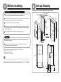
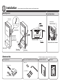
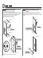
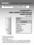
INSTALLATION MANUAL
Clean Dry™
High Speed Concealed Hand Dryer
Warranty Registration and Inquiry
For product warranty registration, TOTO U.S.A. Inc. recommends online Warranty Registration. Please visit our web site http://www.totousa.com. If you have questions regarding warranty policy or
coverage, please contact TOTO U.S.A. Inc., Customer Service Department, 1155 Southern Road, Morrow, GA 30260 (888) 295 8134 or (678)466-1300 when calling from outside of U.S.A.
Important Safeguards
Warning
(For your safety, please follow the instructions below.)
In this Instruction Manual, the following symbols are shown for safe and proper use of
the product and to alert you of the possibility of personal injury and damage to your
property.
The symbols and their meanings are as follows:
Warning
Ignoring these symbols may cause
personal injury and/or property damage.
Caution
Ignoring these symbols may cause
severe injury and/or property damage.
It is necessary to install a circuit-breaker in the power supply
Important
Failure to do this may cause electric shock during overload or short
circuit.
Caution
Important
The chassis assembly must be installed on a smooth and even
wall surface which has enough strength.
Failure to do this may cause damage or personal injury if it falls down.
Specification
*Some models may have different components from the ones illustrated below.
Warning
Do not install the unit in the places where corrosive
or combustible gas can be present.
Do not
This may cause product failure or damage.
Never attempt to disassemble for repair or
modification.
Do not
This may cause electric shock, fire, injury or failure
disassemble
Do not install outdoors or where it is exposed to
water.
Do not use in This may cause current leakage, electric shock, fire, or failure.
humid area
0GU3049E 2009.04
Product
HDR110#SS
Power Rating
120V AC, 4.25 Amps, 60 Hz, 510 W
Power Connection
Hardwiring
Power Saving Function
Automatically turns OFF after 60 seconds of use
Decibel Rating
58 dB
Air Speed
224 mph (100 meters/second)
Dry Time
12 seconds
Drain Tray Capacity
0.27 gal (950 ml)
Ambient temperature
32° - 104°F (0° - 40°C)
Size
9-5/8" x 18-1/2" x 6-5/16"
Weight
22.2 lbs (10kg)
Set-up Drawing
Before Installing
Some models may have different components as illustrated below.
Confirm the rough-in, major dimensions and wiring diagram before installation
in order to properly install the hand dryer and electrical wiring.
3-9/16″ (90mm)
2-3/8″ (60mm)
2-3/8″ (60mm)
1-9/16″ (40mm)
5-1/8″
(130mm)
FINISHED
WALL
Mounting surface should be even and smooth.
Confirmation must be made that the wall has enough strength for hand dryer
installation and be sure to use all the mounting hardware provided to securely
install the hand dryer.
1-9/16″
(40mm)
Junction box
location
26-5/16″
(668mm)
It is necessary to install circuit breaker for the power supply.
2″ (50mm)
1-3/16″ (30mm)
2. Others
2-3/4″ (70mm)
Pay special attention so that both the top cover and the sensor surface are
not flawed or scratched.
2-3/4″ (70mm)
9-15/16″ (252mm)
Recommended mounting bracket heights from floor are as follow:
*- Male/Female:
29-1/2” (750 mm)
28-3/4″
(730mm)
2″
(50mm)
Meets the American Disabilities Act Guidelines, ANSI A117.1 and CSA B651 requirements
when mounted in a recessed wall where the front surface is not more than 4” (102mm) from
finished wall and max. height of air blower outlet from finished floor is 47-1/4” (1200mm).
12-5/8″
(320mm)
1-9/16″
(40mm)
5-1/8″
(130mm)
6-7/16″
(164mm)
26-5/16″ (668mm)
3-1/8″ (80mm)
Do not place other devices using inverter or infrared sensor near the
hand dryer, this may cause malfunction.
- Children: 23-1/2” (598 mm)
- Handicapped: 21-1/2” (547 mm)
11-13/16″
(300mm)
1-5/16″
(34mm)
All electrical wiring should be installed in accordance with national/local codes
and regulations with assistance from a certified electrician.
27-9/16″ - 27-5/8″ (700±2 mm)
1. Precautions
OPEN WALL
*
FLOOR
Installation
*Some models may have different component as illustrated below.
Hand Dryer Unit
w/o Top Cover
Top cover
Sensor
Color : White,Black,Green
Size : AWG16×3
Air nozzles
Power Cable
Junction box
(Connection type)
Wall surface
Wiring Hole
Chassis Assy
<Bottom view>
Filter case
Filter
Water Tray
Filter case
Drain tray
Accessories
※ Model is subject to change without further notification.
Mounting Bracket
Screws and Vandal Resist Hex Wrench Installation Manual
(M4×6) ×2
Bracket (Top)
Installation
position
Bracket (Bottom)
<View with cover removed>
(φ4.5×30) ×6
Template
Installation Procedure
STEP 1
1 Using template provided, mark the wall for locations and install
the mounting bracket.
Wall thickness needs
to be 5 to 30mm.
3-9/16″ (90mm)
1-9/16″
(40mm)
2-3/8″ (60mm)
STEP 1
Caution
2-3/8″ (60mm)
Beam/Stud
Mark the wall with template and install the bracket
Chassis Assy. must be installed on a rigid and even surface
Failure to do this may cause damage or personal injury when it falls.
・ Attach the bracket firmly on the rigid wall with the three screws (φ4.5×30)
provided.
・ In the case of a tile or concrete wall, please use plastic plug anchors with
Bracket
(Top)
Finished
wall
screws provided.
3-9/16″ (90mm)
2-3/8″ (60mm)
1-9/16″ (40mm)
2-3/8″ (60mm)
Junction box
location
1-9/16″
(40mm)
3-1/8″
(80mm)
Finished
wall
2″ (50mm)
2-3/4″
(70mm)
1-3/16″ (30mm)
2-3/4″
(70mm)
Wall thickness needs
to be 5 to 30mm.
1-9/16″
(40mm)
Bracket (Bottom)
Drain tray
2″ (50mm)
Finished Wall
△
Remove drain tray
during installation
Wall
Beam/Stud
1-9/16″ (40mm)
2-3/4″ (70mm)
1-3/16″ (30mm)
2-3/4″ (70mm)
3-1/8″ (80mm)
2 Complete the electrical wiring; install the junction
box, and connect the power cord using wire nuts.
3 Mount the chassis assembly and drain tray assembly
4 Install the top cover and drain tray
Recommended mounting bracket heights from floor are as follow:
*- Male/Female:
29-1/2” (750 mm)
- Children: 23-1/2” (598 mm)
- Handicapped: 21-1/2” (547 mm)
To be continued on the back
STEP 2
STEP 2
-
STEP 3
Complete the electrical wiring
STEP 3
・Place chassis assembly onto the bottom bracket.
・Using wire nuts, connect power cable from hand dryer to power supply in the
junction box (confirm with certified electrician on correct wire nuts to use).
・Place connection point (with wire nuts) into the junction box.
・Hang chassis assembly onto the top bracket.
Mount the Chassis Assembly and Drain Tray
Assembly
・Make sure all electrical wiring is placed away inside the junction box.
・Use 2 screws (M4) that come with the product and tighten unit to the bottom
bracket.
Bracket (Top)
Screw in two screws onto bottom
of body through the bottom bracket
Junction box
(Actual Placement)
Junction box
(Actual Placement)
Connection point
Bracket (Bottom)
Chassis Assembly
Chassis
Assy
Place mounting platform
onto mounting bracket hooks.
Junction box
(Actual Placement)
Place connection point (with
wire nuts) into the junction box
Drain tray
Connection
Diagram
Attach water tray after
installation is complete
※ Connect the cord firmly with a wire nut or equivalent.
Function Test
1. Checking after installation
■ Test the product as follows after the installation is complete.
Wiring Diagram
Sensor
・First peel off the seal on the filter.
(The seal is used to protect the filter from scratches during
shipment; it is no longer needed.)
P6
W
P7
W
P2
Air nozzles
Peel off the seal
1. Check the circuit breaker
Control
Assembly
Power
Connector
・Turn the circuit breaker ON.
2. Check the functionality
・Place your hand under the outlet nozzles to see if air blows out.
・After you check the functionality by trial run, give the user manual
(with warranty) to the customer, and explain how to use and maintain the
product.
B
P1-2
B
Power Fuse
15A
Motor
P3
Motor
W
G
G
■ After trial run
P1-1
W
Body Case
B=BLACK
R=RED
W=WHITE
Bu=BLUE
G=GREEN