1
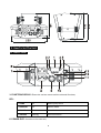
LED-‐245-‐1W RGBA User Manual Please read the instructions carefully before use CONTENTS 1. Safety Instructions....................................................................................................2 2. Technical Specifications............................................................................................3 3. How To Set The Unit.................................................................................................4 3.1 Control Panel ......................................................................................................4 3.2 Main Function ....................................................................................................5 4. How To Control The Unit..........................................................................................9 4.1 Master/Slave Built In Preprogrammed Function................................................9 4.2 Easy CA-‐8 Controller...........................................................................................9 4.3 DMX Controller.................................................................................................10 5. DMX 512 Configuration ..........................................................................................10 6. DMX 512 Connection..............................................................................................11 7. Troubleshooting .....................................................................................................12 8. Fixture Cleaning......................................................................................................13 1 1. Safety Instructions WARNING Please read the instructions carefully as they include important information about installation, operation and maintenance. Please keep this User Guide for future consultation. If you sell the unit to another user, be sure that they also receive this instruction booklet. Unpack and check carefully there is no transportation damage before using the unit. Before operating, ensure that the voltage and frequency of power supply match the power requirements of the unit. It’s important to ground the yellow/green conductor to earth in order to avoid electric shock. The unit is for indoor use only. Use only in a dry location. The unit must be installed in a location with adequate ventilation, at least 50cm from adjacent surfaces. Be sure that no ventilation slots are blocked. Disconnect main power before replacement or servicing. Make sure there are no flammable materials close to the unit while operating as it is a fire hazard. Use safety cables when installing this unit. Maximum ambient temperature is Ta: 40 degrees C. DO NOT operate it where the temperature is higher than this. Turn off the power and allow about 5 minutes for the unit to cool down before servicing. In the event of a serious operating problem, stop using the unit immediately. Never try to repair the unit by yourself. Repairs carried out by unskilled people can lead to damage or malfunction. Please contact the nearest authorized technical assistance center. Always use the same type spare parts. DO NOT touch any cables during operation as high voltage may cause electric shock. Warning: To prevent or reduce the risk of electrical shock or fire, do not expose the unit to rain or moisture. The housing and lenses must be replaced if they are visibly damaged. 2 Installation: The unit should be mounted via its screw holes on the bracket. Always ensure that the unit is firmly fixed to avoid vibration and slipping while operating. Make sure that the structure to which you are attaching the unit is secure and is able to support a weight of 10 times of the unit’s weight. Also always use a safety cable that can hold 12 times of the weight of the unit when installing the fixture. The equipment must be installed by professionals. It must be installed in a place where is out of the reach of people and no one can pass by or under it. 2. Technical Specifications 1 DMX Channel 3 operation modes: DMX, Master/Slave and Sound Active Built-‐in programs in Master/Slave operation triggered by the music Optional easy controller CA-‐8 for instant lighting shows Power Voltage: AC 100~240V, 50/60Hz Power Consumption: 35W Power Cable Daisy Chains: 20 Fixtures Max. (230V, 50Hz) 12 Fixtures Max. (120V, 60Hz) LED Source: 18 x 1W RGBA LEDs (R: 4pcs; G: 4pcs; B: 4pcs; A: 6pcs) Beam Angle: 5° Weight: 2.6kgs Dimension: 246 x 230 x 164mm 3 3. How To Set The Unit 3.1 Control Panel 1. FUNCTION DISPLAY: Shows the various menus and the selected functions; LED: 2. DMX On DMX input present 3. MASTER On Master Mode 4. SLAVE On Slave Mode 5. SOUND Flashing Sound activation 6. POWER OUT: Connects to the next unit; 4 7. FUSE (T 3.15A): Protects the unit from over-‐voltage or short circuit 8. POWER IN: Connects to mains supply power; 9. DMX IN: DMX 512 link, use a 3-‐pin XLR cable to link the unit to a DMX controller; 10. DMX OUT: DMX 512 link, use a 3-‐pin XLR cable to link to the next unit; 11. MICROPHONE: Receives music signals for sound active mode 12. BUTTON: MENU To select the programming functions DOWN To go backward in the selected functions UP To go forward in the selected functions ENTER To confirm the selected functions 13. ONLY FOR REMOTE CONTROL: Connects with the optional CA-‐8 to control the unit 3.2 Main Function To select any of the given functions, press the MENU button up to the required selection as shown on the display. Select the function with the ENTER button and the display will blink. Use the DOWN/UP buttons to change the mode. Once the required mode has been selected, press the ENTER button to confirm. To go back to the main functions without any changes press the MENU button again. Press and hold the MENU button for about one second or wait for 7 seconds to exit the current mode. 5 The main functions are shown below: DMX 512 ADDRESS To select , press the ENTER button to show DMX ADDRESS on the display. Use the DOWN/UP buttons to adjust the address from 1 to 512. Once the address has been selected, press the ENTER button to select. To go back to the functions without any changes press the MENU button again. Press and hold the MENU button for about one second or wait for 7 seconds to exit the current mode. 6 SHOW MODE To select , press the ENTER button to show SHOW MODE on the display. Use the DOWN/UP buttons to select (Random show), (Show 1) up to (Show 12) mode. Once the mode has been selected, press the ENTER button to setup. To go back to the functions without any changes press the MENU button again. Press and hold the MENU button for about one second or wait for 7 seconds to exit the current mode. SLAVE MODE To select , press the ENTER button to show SLAVE MODE on the display. Use the DOWN/UP buttons to select (master), (Slave 1), (Slave 2) mode. Once the mode has been selected, press the ENTER button to setup. To go back to the functions without any changes press the MENU button again. Press and hold the MENU button for about one second or wait for 7 seconds to exit the current mode. SOUND MODE To select , press the ENTER button to show SOUND MODE on the display. Use the DOWN/UP buttons to select (sound on) or (sound off) mode. Once the mode has been selected, press the ENTER button to setup To go back to the functions without any changes press the MENU button again. Press and hold the MENU button for about one second or wait for 7 seconds to exit the current mode. BLACKOUT MODE To select , press the ENTER button to show BLACKOUT MODE on the display. Use the DOWN/UP buttons to select (blackout) or (normal) mode. Once the mode has been selected, press the ENTER button to setup. To go back to the functions without any changes press the MENU button again. Press and hold the MENU button for about one second or wait for 7 seconds to exit the current mode. DISPLAY INVERSE To select , press the ENTER button to show DISPLAY on the display. Press the ENTER 7 button again and it will show the (inversion). To go back to the functions without any changes press the MENU button. LED DISPLAY To select , press the ENTER button to show LED on the display. Use the DOWN/UP buttons to select (LED on) or (LED off) mode. Once the mode has been selected, press the ENTER button to setup. To go back to the functions without any changes press the MENU button again. Press and hold the MENU button for about one second or wait for 7 seconds to exit the current mode. AUTO TEST To select , press the ENTER button to show TEST on the display and the unit will run a self-‐test . To go back to the functions without any changes press the MENU button again. Press and hold the MENU button for about one second or wait for 7 seconds to exit the current mode. FIXTURE HOURS To select , press the ENTER button to show FIXTURE HOURS on the display and the display will show the number of working hours of the unit . To go back to the functions without any changes press the MENU button again. Press and hold the MENU button for about one second or wait for 7 seconds to exit the current mode. SOFTWARE VERSION To select , press the ENTER button to show SOFTWARE VERSION on the display and the display will show the version of the software of the unit . To go back to the functions without any changes press the MENU button again. Press and hold the MENU button for about one second or wait for 7 seconds to exit the current mode. 8 4. How To Control The Unit You can operate the unit in three ways: 1. Master/slave built-‐in preprogram function 2. Easy controller (optional CA-‐8) 3. Universal DMX controller You do not need to turn the unit off when you change the DMX address, the new DMX address setting will take effect immediately. 4.1 Master/Slave Built In Preprogrammed Function By linking the units in master/slave mode, the first unit will control the other units to give an automatic, sound activated, synchronized light show. This function is good when you want an instant show. You have to set the first unit in master mode and select (show 1) or… or and select (random show) or (show 12) mode. Any other units will have to be set in slave mode (normal) or (2-‐light show) mode. 2-‐light show In (slave mode), means the unit works normally and In order to create a great light show, you can set means 2-‐light show. on the second unit to get contrast movement to each other. 4.2 Easy Controller The easy CA-‐8 remote control is used only in master/slave mode. By connecting to the 1/4” jack socket of the first unit you will find that the remote control in the first unit will control all the other units for Stand by, Function and Mode selection. Blackout Function Mode Blackout the unit Strobe 1. Synchronous strobe 2. Sound strobe in 3. Sound strobe in color Sound (LED OFF) Select Show Show 1~12 Show (LED ON) 9 4.3 DMX Controller When using a universal DMX controller to control the units, you must set a DMX address from 1 to 512. Press the MENU button up to when is showing on the display. Press the ENTER button and the display will blink. Use the DOWN/UP buttons to change the DMX 512 address. Once the address has been selected, press and hold the ENTER button until the display stops blinking or it will store automatically after 7 seconds. To go back to the functions without any changes press the MENU button again. 5. DMX 512 Configuration 1 Channels Mode: 10 6. DMX512 Connection 1. The last units DMX cable has to be terminated with a 120 ohm 1/4W resistor between pin 2(DMX-‐) and pin 3(DMX+) of a 3-‐pin XLR-‐plug and plug it in the DMX-‐output of the last unit. 2. Connect the unit together in a `daisy chain` by XLR plug from the output of the unit to the input of the next unit. The cable can not branched or split to a `Y` cable. 3. The DMX output and input connectors are pass-‐through type to maintain the DMX circuit even when one of the units’ power is disconnected. 4. Each fixture unit needs to have an address set to receive the data sent by the controller. The address number is between 0-‐512 (usually 0 & 1 are equal to 1). 5. The end of the DMX 512 system should be terminated to reduce signal errors. 3 pin XLR: Pin 1: GND, Pin 2: Negative signal (-‐), Pin 3: Positive signal (+) 11 7. Troubleshooting Following are a few common problems that may occur during operation. Here are some suggestions for easy troubleshooting: A. The unit does not work, no light and the fan does not work 1. Check the connection of power and the main fuse. 2. Check the power on LED. B. Not responding to DMX controller 1. DMX LED should be on. If not check the DMX cables to see if linked correctly. 2. If the DMX LED is on but no response check the address settings and DMX polarity. 3. If you have intermittent DMX signal problems check the cables. 4. Try another DMX controller. C. Some units don’t respond to the easy controller 1. You may have a break in the DMX cabling. Check the LED for the response of the master/ slave mode signal. 2. Wrong DMX address in the unit. Set the correct address. D. No response to the sound 1. Make sure the unit is set into the correct mode. 2. Check the microphone by tapping it. 3. Make sure the fixture is not set into Blackout mode 12 8. Fixture Cleaning Cleaning must be carried out periodically to optimize light output. Cleaning frequency depends on the environment in which the fixture operates: moist, smoky or particularly dirty surroundings can cause a greater accumulation of dirt on the fixture. Clean with soft cloth using normal glass cleaning fluid or mild soapy water. Always dry the parts carefully. Clean the external optics at least every 30 days. 13 Declaration of Conformity We declare that our products (lighting equipments) comply with the following specification and bears CE mark in accordance with the provision of the Electromagnetic Compatibility (EMC) Directive 89/336/EEC. EN55103-‐1: 2009 ; EN55103-‐2: 2009; EN62471: 2008; EN61000-‐3-‐2: 2006 + A1:2009 + A2:2009; EN61000-‐3-‐3: 2008. & Harmonized Standard EN 60598-‐1:2008 + All:2009; EN 60598-‐2-‐17:1989 + A2:1991; EN 62471:2008; EN 62493: 2010 Safety of household and similar electrical appliances Part 1: General requirements 14 Innovation, Quality, Performance 15