1
Control & Communication Link
System Master/Local Module
User’s Manual
(Hardware)
AJ61QBT11
A1SJ61QBT11
Thank you for buying the Mitsubishi general-purpose programmable
logic controller MELSEC-QnA Series
Prior to use, please read both this manual and detailed manual
thoroughly and familiarize yourself with the product.
MODEL AJ61QBT11-U-H-JE
MODEL
13JT19
CODE
IB(NA)-0800147-D(0706)MEE
©2000 MITSUBISHI ELECTRIC CORPORATION
z SAFETY PRECAUTIONS z
(Always read before starting use)
When using this equipment, thoroughly read this manual. Also pay careful
attention to safety and handle the module properly.
These precautions apply only to this equipment.
Refer to the user’s manual of the CPU module to use for a description of the
PLC system safety precautions.
These "Safety Precautions" classify the safety precautions into two categories:
"DANGER" and "CAUTION".
DANGER
Procedures which may lead to a dangerous condition and
cause death or serious injury, if not carried out properly.
CAUTION
Procedures which may lead to a dangerous condition and
cause superficial to medium injury, or physical damage
only, if not carried out properly.
Depending on circumstances, procedures indicated by
CAUTION may also
be linked to serious results.
In any case, it is important to follow the directions for usage.
Store this manual in a safe place so that you can take it out and read it
whenever necessary. Always forward it to the end user.
[DESIGN PRECAUTIONS]
DANGER
z Read Chapter 5 in this manual carefully for status of each station when the
PLC CPU has stopped its operation and when a communication error
occurred in the data link.
Configure an interlocking circuit in a sequence program using the
communication status information (SB, SW) so that the safety of the overall
system is always maintained.
Accident may occur due to output error or malfunctioning.
z The master station or local station cannot detect errors when a station
specified as an error-invalidated station becomes communication error.
CAUTION
z Do not bundle, on install, the control cables and communication cables
with, or near, main circuit and power cables. Keep them at least 100 mm
(3.9 in.) away from such cables. Noise may cause erroneous operation.
A-1
[INSTALLATION PRECAUTIONS]
CAUTION
z Use the PLC in the environment given in the general specifications section
of the User’s manual for CPU module being used. Using the PLC outside
the range of the general specifications may result in electric shock, fire or
erroneous operation or may damage or degrade the product.
z Insert the tabs at the bottom of the module into the holes in the base unit
before installing the module. Improper installation may cause erroneous
operation, accidents, or the module to fall out.
z Do not touch the electronic parts or the module conduction area. It may
cause erroneous operation or failure.
[WIRING PRECAUTIONS]
DANGER
z Before beginning any installation or wiring work, make sure all phases of
the power supply have been obstructed from the outside. Failing to
completely shut out the power supply phases could cause electrical shock
and/or damage to the product.
z Following installation or wiring work, when turning on the power supply and
operating the equipment, make sure the terminal cover provided as an
accessory has been attached to the product.
Failure to attach the terminal covers may result in malfunction.
CAUTION
z Use applicable solderless terminals and tighten them with the specified
torque. If any solderless spade terminal is used, it may be removed when
the terminal screw comes loose, resulting in failure.
z Tighten the terminal screws to the specified torque. Loose terminal screws
may cause a short circuit or erroneous operation.
z Be sure that cuttings, wire chips, or other foreign matter do not enter the
module. Foreign matter may start a fire or cause an accident or erroneous
operation.
z Always place electric wires or cables connected to the module in ducts or
fix them with clamps.
If not, dangling cables may be shifted or inadvertently pulled, resulting in
damages to the module or cables or malfunctions due to poor cable
contact.
z Do not install the control cables and communication cables together and
not let them close to each other.
Doing so may cause malfunction due to noise.
A-2
[WIRING PRECAUTIONS]
CAUTION
z Do not grab on the cable when removing the communication cable
connected to the module.
When removing the cable with a connector, hold the connector on the side
that is connected to the module.
When removing the cable without a connector, loose the screws on the
side that is connected to the module.
Pulling the cable that is still connected to the module may cause
malfunction due to bad cable contacts.
[STARTING AND MAINTENANCE PRECAUTIONS]
DANGER
z Do not touch terminals without obstructing all power supply from the
outside.
It may cause malfunction.
z Turn off the power before cleaning the module or retightening the screws.
Doing this work while the power is on may damage the module or cause
erroneous operation.
z Do not disassemble or rebuild the module. It may cause accidents,
erroneous operation, injury, or fire.
z Turn off the power before mounting and dismounting the module. Mounting
or dismounting the module while the power is on may damage the module
or cause erroneous operation.
[DISPOSAL PRECAUTIONS]
CAUTION
z When disposing of this product, treat it as industrial waste.
A-3
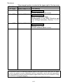
Revisions
Print Date
Jul.,2000
Nov.,2000
Mar.,2006
Jun.,2007
* The manual number is noted at the lower right of the top cover.
*Manual Number
Revision
IB(NA)-0800147-A First printing
IB(NA)-0800147-B
Partial correction
Contact address (Back cover)
IB(NA)-0800147-C
Partial correction
SAFETYPRECAUTIONS,
Conformation to the EMC Directive and
Low Voltage Instruction, Section 1.1, 2.1,
5.1
IB(NA)-0800147-D
Partial correction
Section 3, 6.1, 6.2,
Contact address (Back cover)
This manual confers no industrial property rights or any rights of any other kind, nor does
it confer any patent licenses. Mitsubishi electric Corporation cannot be held responsible
for any problems involving industrial property rights which may occur as a result of using
the contents noted in this manual.
© 2000 MITSUBISHI ELECTRIC CORPORATION
A-4
CONTENTS
1. Overview ....................................................................................................... 1
1.1 Definition of Ver.1.10................................................................................ 2
2. Performance Specification ............................................................................ 3
2.1 Performance specification ........................................................................ 3
2.1.1 Maximum overall cable distance.......................................................... 4
2.2 CC-Link dedicated cable .......................................................................... 4
3. Name and Setting of Each Component ......................................................... 5
4. Loading and Installation ................................................................................ 9
4.1 Handling precautions ............................................................................... 9
4.2 Installation environment ........................................................................... 9
5. External Wiring ........................................................................................... 10
5.1 Wiring the CC-Link dedicated cable ....................................................... 10
6. External Dimensions ................................................................................... 11
6.1 AJ61QBT11 ........................................................................................... 11
6.2 A1SJ61QBT11 ....................................................................................... 12
A-5
About the Manuals
The following product are available for this equipment.
Refer to the table given below to choose suitable manuals.
Related Manual
Manual name
Control & Communication Link System Master/Local
Module type AJ61QBT11/A1SJ61QBT11 User's Manual
Manual No.
(Model code)
IB-66722
(13J873)
Conformation to the EMC Directive and Low Voltage Instruction
When incorporating a Mitsubishi PLC that is compliant with the EMC and low
voltage directives into any other product and ensuring compliance with these
directives, refer to Chapter 3 "EMC and Low Voltage Directives" of the User's
Manual (Hardware) for the PLC CPU included with the CPU module or base
unit.
A module compliant with the EMC and low voltage directives bears a CE
mark logo printed on the rating plate.
To make this product compliant with the EMC and low voltage directives,
refer to "CC-Link module" in Chapter 3 "EMC and Low Voltage Directives" of
the User's Manual (Hardware) for the CPU module.
A-6
1. Overview
This manual describes the specifications, name of each part, settings, etc., of
the AJ61QBT11 Control & Communication Link System Master/Local Module
(hereafter abbreviated as AJ61QBT11) and A1SJ61QBT11 Control &
Communication Link System Master/Local Module (hereafter abbreviated as
A1SJ61QBT11) to be used in combination with the MELSEC-QnA series PLC
CPU.
In this manual, Control & Communication Link is abbreviated as CC-Link.
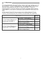
Confirm if the following items are included in the package after unpacking.
Item name
CC-Link System Master/Local
Module type AJ61QBT11
CC-Link System Master/Local
Module type A1SJ61QBT11
AJ61QBT11 main module
Terminal resistor 110Ω 1/2W
(Brown-brown-brown)
Terminal resistor 130Ω 1/2W
(Brown-orange-brown)
A1SJ61QBT11 main module
Terminal resistor 110Ω 1/2W
(Brown-brown-brown)
Terminal resistor 130Ω 1/2W
(Brown-orange-brown)
1
Number
of items
1
2
2
1
2
2
1.1 Definition of Ver.1.10
The module of which the cable length between station and station is uniformly
20cm or more by improving the conventional limit of the cable length between
station and station is defined as Ver.1.10.
The conventional modules are defined as Ver.1.00.
The conditions for setting the cable length between station and station uniformly
to 20cm or more are indicated below.
1) All modules configuring the CC-Link system must use Version 1.10.
2) All data link cables must be Version 1.10 compatible CC-Link
dedicated cable.
Point
In the case of the system containing modules of both Ver.1.00 and
Ver.1.10, the maximum overall cable length and the station-to-station cable
length must meet the specifications for Ver.1.00.
(1) Checking Version 1.10
The “CC-Link” logo is stamped on the “plate” for the Version 1.10
modules.
2
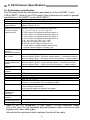
2. Performance Specification
2.1 Performance specification
The following shows the performance specification of the AJ61QBT11 and
A1SJ61QBT11. Refer to the CPU module User's Manual to be used for general
specification of AJ61QBT11 and A1SJ61QBT11.
Item
Transmission speed
Maximum overall
cable distance
Maximum number of
modules that can be
connected (when
master station)
Number of occupied
stations
(When local station)
Maximum link points
per system
Link point per
remote station/local
station
Communication
method
Synchronous
method
Signed method
Transmission path
Transmission format
Error control system
Cable
RAS function
Specification
156kbps/625kbps/2.5Mbps/5Mbps/10Mbps selectable
It differs depending on transmission speed
(Refer to Section 2.1.1)
64 units
However, the following conditions must be met:
{(1 × a) + (2 × b)+ (3 × c) + (4 × d)} ≤ 64
a: The number of occupied modules by station 1.
b: The number of occupied modules by station 2.
c: The number of occupied modules by station 3.
d: The number of occupied modules by station 4.
{(16 × A) + (54 × B) + (88 × C)} ≤ 2304
A: Remote I/O station's numbers ≤ 64
B: Remote device station's numbers ≤ 42
C: Local station's ,standby master station's and
intelligent device station's numbers ≤ 26
1 station to 4 stations (Switched by DIP switch)
Remote I/O (RX, RY): 2048 points
Remote register (RWw): 256 points (master station → remote/local station)
Remote register (RWr): 256 points (remote/local station → master station)
Remote I/O (RX, RY): 32 points (local station 30 points)
Remote register (RWw): 4 points (master station → remote/local station)
Remote register (RWr): 4 points (remote/local station → master station)
Broadcast polling method
Frame synchronous method
NRZI method
Bus (RS-485)
Conform to HDLC
CRC (X16+X12+X5+1)
CC-Link dedicated cable/CC-Link dedicated high-performance cable
/Version 1.10 compatible CC-Link dedicated cable*
• Auto return function
• Slave station cutoff function
• Link special relay/Error detection by register
10000 times
Parameter entry
numbers for
2
E PROM
I/O occupied points
32 points (I/O allocation: special 32 points)
number
Internal consumption AJ61QBT11:0.45, A1SJ61QBT11:0.4
current (5VDC) (A)
Weight [kg]
AJ61QBT11:0.4 , A1SJ61QBT11:0.25
* Each of Ver.1.10 compatible CC-Link cables, CC-Link dedicated cables
(Ver.1.00), and CC-Link dedicated high-performance cables cannot be used
together with other cable types.
Also attach the terminator which matches the kind of the cable.
3
2.1.1 Maximum overall cable distance
The maximum overall cable distance differs according to the transmission
speed.
For the relationship between the transmission speed and maximum overall
cable distance, refer to CC-Link Catalog.
2.2 CC-Link dedicated cable
Use the CC-Link dedicated cables in a CC-Link system.
The performance of the CC-Link system cannot be guaranteed with cables
other than the CC-Link dedicated cables.
For the specifications of the CC-Link dedicated cable and the reference office,
refer to CC-Link catalog.
4
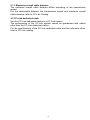
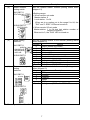
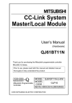
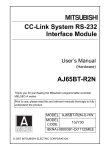
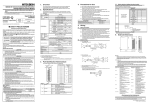
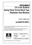
3. Name and Setting of Each Component
This section explains the name and setting of each component of AJ61QBT11
and A1SJ61QBT11.
AJ61QBT11
156K
625K
2.5M
5M
10M
RUN
ERR.
MST
S MST
LOCAL
CPU R/W
E
R
R
O
R
SW
M/S
PRM
TIME
LINE
TEST
S0
S1
S2
B
R
A
T
E
(1)
T
E
S
T
SD
RD
L RUN
L ERR.
A1SJ61QBT11
(2)
45
23 6
4 56
456
456
456
23
6789A
23
23
345
4 56
23
23
23
OFF
ON
M/L
S MST
CLEAR HOLD
1/2
3/4
1/4
2/3
-
KSD08
B RATE
0 156K
1 625K
2 2.5M
3 5M
4 10M
ON SW
1
2
3
4
5
6
7
8
SD
RD
ON
78
(3)
SW OFF ON
1 M/L S.M
2 3 4 CLR HLD
5 1/2 3/4
6 1/4 2/3
7 8 -
(5)
NC
1
DA
NC
2
NC
4
NC
6
NC
8
3
DB
(5)
5
DG
7
SLD
9
NC
(FG)
1
DA
NC
2
A1SJ61QBT11
3
DB
NC
4
NC
6
NC
8
5
DG
(6)
7
SLD
9
(FG)
10
5
(1)
C
AB DE
(4)
78
901
(4)
X
1
901
78
(2)
1 2 3 4 5 6 7 8
(3)
90 1
B RATE
0 156K
1 625K
2 2.5M
3
5M
4 10M
BCD
0
EF 12
MODE
0:ONLINE(A.R.)
1:ONLINE(RIM)
2:OFFLINE
E
R
R
O
R
STATION NO.MODE
789
78
X
10
90 1
901
X1
78
SW
M/S
PRM
TIME
LINE
F01
45 6
78
9 01
STATION NO.
X10
RUN
ERR.
MST
S MST
LOCAL
CPU R/W
L RUN
L ERR.
10
(6)
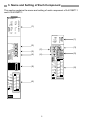
Number
(1)
Name
LED display
A J61QBT11
B
RUN
ERR.
MST
S MST
LOCAL
CPU R/W
E
R
R
O
R
SW
M/S
PRM
TIME
LINE
L RUN
L ERR.
156K
625K
2.5M
5M
10M
R
A
T
E
TEST
S0
S1
S2
T
E
S
T
SD
RD
A1SJ61QBT11
RUN
ERR.
MST
S MST
LOCAL
CPU R/W
L RUN
L ERR.
SW
M/S
PRM
TIME
LINE
SD
RD
E
R
R
O
R
Description
Data link status can be confirmed by LED's ON state.
LED display
Description
RUN
ON: When module is normal.
OFF: When watchdog timer error.
ERR.
ON: All stations communication error.
Blink:Communication error occured in the
station.
MST
ON: It is set at the master station.
S MST
ON: It is set at the standby master
station.
LOCAL
ON: It is set at the local station.
CPU R/W
ON: It is communicating with PLC CPU.
(FROM/TO)
SW
ON: Settings for switches are not
normal.
M/S
ON: Master station is overlapped on the
E
same line.
R
PRM
ON: An error occurred in the parameter
R
content.
O
TIME
ON: Data link monitor timer is started.
R
LINE
ON Cables
are
disconnected
or
transmission path is affected by
noise, etc.
L RUN
ON: Data link is operating. (host station)
L ERR.
ON: Communication error (host station).
Blink:The settings of switches 2 to 5 are
changed during the power supply
ON.
156K
ON: When transmission speed is set to
"156kbps".
ON: When transmission speed is set to
B 625K
"625kbps".
R 2.5M
ON: When transmission speed is set to
A
"2.5Mbps".
T 5M
ON: When transmission speed is set to
E
"5Mbps".
10M
ON: When transmission speed is set to
"10Mbps".
T TEST
ON: Offline test in progress.
E S0
Not used
S S1
T S2
SD
ON: Data being sent.
RD
ON: Data being received.
6
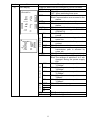
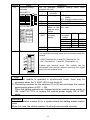
Number
(2)
Name
Station number
setting switch
Description
Set the module station number.(Setting status when
shipped: 0)
AJ61QBT11
456
23
456
78
901
23
X1
78
901
STATION NO.
X10
A1SJ61QBT11
456
901
STATION NO.
78
X
10
23
456
23
(3)
78
Mode setting
switches
AJ61QBT11
89
67 A
BCD
01
EF 2
345
MODE
0:ONLINE(A.R.)
1:ONLINE(RIM)
2:OFFLINE
A1SJ61QBT11
MODE
8
4
C
0
(4)
When set to a number not in the range 0 to 64, the
"SW" and "L ERR." LEDs are turned on.
• When remote I/O net mode
Master station: 1 to 64 (set last station number of
remote I/O station)
When set to 0, the "PLM" LED is turned on.
901
X
1
<Setting range>
• When remote net mode
Master station: 0
Local station: 1 to 64
Transmission speed
setting
switches
AJ61QBT11
456
78
901
23
B RATE
0 156K
1 625K
2 2.5M
3
5M
4 10M
Set the operation status of the module (Setting status
when shipped: 0)
Number
Names
0
Online (remote net mode)
1
Online (remote I/O net mode)
2
Offline
3
Line test 1 *1
4
Line test 2 *1
5
Parameter confirmation test *1
6
Hardware test
7
Setting error ("SW" LED turn on)
8 to A
Setting prohibited due to internal use
B to F
Setting error ("SW" LED turn on)
Set transmission status of the module (Setting status
when shipped: 0)
Number
Descriptions
0
156kbps
1
625kbps
2
2.5Mbps
3
5Mbps
4
10Mbps
5 to 9
Setting error ("SW" or "L ERR" LED turn on)
0
5
A1SJ61QBT11
B RATE
0 156K
1 625K
2 2.5M
3 5M
4 10M
*1: Use impossible at local station.
7
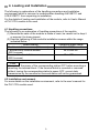
Number
(5)
Name
Condition setting
switches
AJ61QBT11
ON SW
1
2
3
4
5
6
7
8
OFF
ON
M/L
S MST
CLEAR HOLD
1/2
3/4
1/4
2/3
-
A1SJ61QBT11
ON
KSD08
1 2 3 4 5 6 7 8
(6)
SWOFF ON
1 M/L S.M
2 3 4 CLR HLD
5 1/2 3/4
6 1/4 2/3
7 8 -
Terminal block
DA
NC
1
NC
2
NC
4
NC
SLD
NC
6
DB
DG
(FG)
3
5
7
8
9
10
Description
Set the operation condition (Setting status when
shipped: All is off)
Numbe
Setting
Description
r
contents
SW1
Station type
OFF: Master station/Local
station
ON : Standby master station
SW2
(Unusable)
Always OFF
SW3
(Unusable)
Always OFF
SW4
Input
data OFF: Clear
status of the ON : Hold
data link error
station
SW5
Number
of Number of
SW5
SW6
SW6
occupied
occupied
station
station
1 station
OFF
OFF
2 stations
OFF
ON
3 stations
ON
ON
4 stations
ON
OFF
SW7
(Unusable)
Always OFF
SW8
(Unusable)
Always OFF
Connecting the CC-Link dedicated cable of data link.
The terminals showing below are connected inside the
module.
• SLD (Terminal No. 8) and FG (Terminal No. 10)
• NC (Terminal No. 7) and NC (Terminal No. 9)
2-piece type terminal block. The module can be
exchanged with another without removing the signal
lines from the terminal block.
Point
(1) When the module is operated in synchronous mode, there may be
occasions when the "L RUN" LED is only faintly lit.
(2) The setting contents for the switches (2) to (5) are valid when the module
power supply status is OFF → ON.
When the setting contents are changed while the module power supply is
ON, reset PLC CPU or turning the module power supply ON to OFF
again.
Important
Do not use station number 64 in a system where the waiting master station
exists.
When it is used, the station number 64 will not communicate correctly.
8
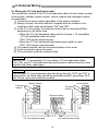
4. Loading and Installation
The following is explanations of the handling precautions and installation
environment which is common to modules when handling AJ61QBT11 and
A1SJ61QBT11 from unpacking to installation.
For the details of loading and installation of the module, refer to User's Manual
of PLC CPU module to be used.
4.1 Handling precautions
The following is an explanation of handling precautions of the module.
(1) Because the case of the module is made of resin, be careful not to drop it
or expose it to strong impact.
(2) Execute tightening of the module's installation screws within the range
indicated below.
Screw location
Tightening torque range
Module installation screws (M4 screws)
78 to 118N·cm
Terminal-block terminal screws
59 to 88N·cm
(M3.5 screws)
Terminal-block installation screws
49 to 78N·cm
(M3.5 screws)
Point
Always turn the power of the corresponding station OFF before mounting or
removing the terminal block. If the terminal bolck is mounted or removed
without turning the corresponding station's power OFF, correct data
transmission by the mounted or removed station will not be guaranteed.
4.2 Installation environment
For more details on the installation environment, refer to the user's manual for
the PLC CPU module used.
9
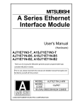
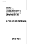
5. External Wiring
5.1 Wiring the CC-Link dedicated cable
The connection method of the CC-Link dedicated cables for the master module,
local module, standby master module, remote module and intelligent module
are described.
(1) Connections can be made regardless of the station numbers.
(2) Always connect "terminal resistors" supplied with the module to the
modules at both ends and between "DA" and "DB".
(3) In the CC-Link system, the terminal resistor that is connected differs
depending on the cable used.
y When the CC-Link dedicated cable and the Version 1.10 compatible
CC-Link dedicated cable are used:
110Ω 1/2W (brown-brown-brown)
y When the CC-Link dedicated high-performance cable is used:
130Ω 1/2W (brown-orange-brown)
(4) The master module can be connected besides to the ends.
(5) A star connection cannot be used.
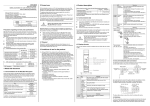
(6) The connection method is shown below.
Important
Each of Ver.1.10 compatible CC-Link cables, CC-Link dedicated cables
(Ver.1.00), and CC-Link dedicated high-performance cables cannot be used
together with other cable types.
Point
The shielded CC-Link dedicated cable should go through "SLD" and "FG" in
each module, and both ends should be grounded (class-D grounding). SLD
and FG are connected inside the module.
Master module
Terminal
resistor
Local module
Terminal
resistor
NC
DA
NC
DA
NC
NC
DB
DB
NC
DG
Remote module
DG
DA DG +24V 24G
SLD
DB SLD FG
FG
NC
SLD
NC
NC
FG
CC-Link dedicated cable
CC-Link dedicated cable
10
NC
NC
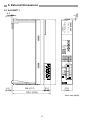
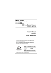
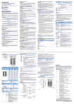
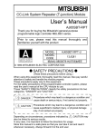
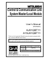
6. External Dimensions
6.1 AJ61QBT11
2
(0.08)
4.2
(0.17)
A J61QBT11
RUN
ERR.
MST
S MST
LOCAL
CPU R/W
E
R
R
O
R
156K
625K
2.5M
5M
10M
SW
M/S
PRM
TIME
LINE
TEST
S0
S1
S2
STATION NO.
X10
78
45 6
SD
RD
R
A
T
E
T
E
S
T
901
L RUN
L ERR.
B
23
456
78
90 1
X1
23
8
67 9A
345
45 6
78
23
156K
625K
2.5M
5M
10M
90 1
B RATE
0
1
2
3
4
BCD
EF012
MODE
0:ONLINE(A.R.)
1:ONLINE(RIM)
2:OFFLINE
ON SW
1
2
3
4
5
6
7
8
OFF
ON
M/L
S MST
CLEAR HOLD
1/2
3/4
1/4
2/3
-
NC
1
DA
NC
2
NC
4
NC
6
NC
8
3
DB
5
DG
7
SLD
9
(FG)
4.2
(0.17)
23.1
(0.90)
106 (4.17)
129.1 (5.08)
10
37.5
(1.48)
Unit: mm (inch)
11
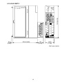
6.2 A1SJ61QBT11
A1SJ61QBT11
RUN
ERR.
MST
S MST
LOCAL
CPU R/W
L RUN
L ERR.
STATION NO.
E
R
R
O
R
SD
RD
MODE
4
C
5
8
0
X
10
SW
M/S
PRM
TIME
LINE
KSD08
SW OFF ON
1 M/L S.M
2 3 4 CLR HLD
5 1/2 3/4
6 1/4 2/3
7 8 -
130 (5.12)
0
5
5
0
ON
0
B RATE
0 156K
1 625K
2 2.5M
3 5M
4 10M NC
1 2 3 4 5 6 7 8
X
1
1
DA
NC
2
NC
4
NC
6
NC
8
3
DB
5
DG
7
SLD
9
(FG)
10
A1SJ61QBT11
6.5
(0.26)
93.6 (3.69)
24
(0.94)
34.5
(1.36)
Unit: mm (inch)
12
Warranty
Mitsubishi will not be held liable for damage caused by factors found not to be the cause of
Mitsubishi; machine damage or lost profits caused by faults in the Mitsubishi products;
damage, secondary damage, accident compensation caused by special factors
unpredictable by Mitsubishi; damages to products other than Mitsubishi products; and to
other duties.
For safe use
y This product has been manufactured as a general-purpose part for general industries,
and has not been designed or manufactured to be incorporated in a device or system
used in purposes related to human life.
y Before using the product for special purposes such as nuclear power, electric power,
aerospace, medicine or passenger movement vehicles, consult with Mitsubishi.
y This product has been manufactured under strict quality control. However, when installing
the product where major accidents or losses could occur if the product fails, install
appropriate backup or failsafe functions in the system.
Country/Region Sales office/Tel
Country/Region Sales office/Tel
U.S.A
Mitsubishi Electric Automation Inc.
Hong Kong
Mitsubishi Electric Automation
(Hong Kong) Ltd.
500 Corporate Woods Parkway Vernon
10th Floor, Manulife Tower, 169 Electric
Hills, IL 60061, U.S.A.
Road, North Point, Hong Kong
Tel : +1-847-478-2100
Tel : +852-2887-8870
Brazil
MELCO-TEC Rep. Com.e Assessoria
China
Mitsubishi Electric Automation
Tecnica Ltda.
(Shanghai)
Ltd.
Rua Correia Dias, 184,
4/F Zhi Fu Plazz, No.80 Xin Chang Road,
Edificio Paraiso Trade Center-8 andar
Shanghai 200003, China
Paraiso, Sao Paulo, SP Brazil
Tel : +86-21-6120-0808
Tel : +55-11-5908-8331
Taiwan
Setsuyo Enterprise Co., Ltd.
Germany
Mitsubishi Electric Europe B.V. German
6F No.105 Wu-Kung 3rd.Rd, Wu-Ku
Branch
Hsiang, Taipei Hsine, Taiwan
Gothaer Strasse 8 D-40880 Ratingen,
Tel : +886-2-2299-2499
GERMANY
Korea
Mitsubishi Electric Automation Korea
Co., Ltd.
Tel : +49-2102-486-0
1480-6, Gayang-dong, Gangseo-ku
U.K
Mitsubishi Electric Europe B.V. UK
Seoul 157-200, Korea
Branch
Tel : +82-2-3660-9552
Travellers Lane, Hatfield, Hertfordshire.,
Singapore
Mitsubishi Electric Asia Pte, Ltd.
AL10 8XB, U.K.
307 Alexandra Road #05-01/02,
Tel : +44-1707-276100
Mitsubishi Electric Building,
Italy
Mitsubishi Electric Europe B.V. Italian
Singapore 159943
Branch
Tel : +65-6470-2460
Centro Dir. Colleoni, Pal. Perseo-Ingr.2
Thailand
Mitsubishi Electric Automation (Thailand)
Via Paracelso 12, I-20041 Agrate Brianza.,
Co., Ltd.
Milano, Italy
Bang-Chan Industrial Estate No.111
Tel : +39-039-60531
Moo 4, Serithai Rd, T.Kannayao,
Spain
Mitsubishi Electric Europe B.V. Spanish
A.Kannayao, Bangkok 10230 Thailand
Branch
Tel : +66-2-517-1326
Indonesia
P.T. Autoteknindo Sumber Makmur
Carretera de Rubi 76-80,
Muara Karang Selatan, Block A/Utara
E-08190 Sant Cugat del Valles,
No.1 Kav. No.11 Kawasan Industri
Barcelona, Spain
Pergudangan Jakarta - Utara 14440,
Tel : +34-93-565-3131
P.O.Box 5045 Jakarta, 11050 Indonesia
France
Mitsubishi Electric Europe B.V. French
Tel : +62-21-6630833
Branch
India
Messung Systems Pvt, Ltd.
25, Boulevard des Bouvets, F-92741
Electronic Sadan NO:III Unit No15,
Nanterre Cedex, France
M.I.D.C Bhosari, Pune-411026, India
TEL: +33-1-5568-5568
Tel : +91-20-2712-3130
South Africa
Circuit Breaker Industries Ltd.
Australia
Mitsubishi Electric Australia Pty. Ltd.
Private Bag 2016, ZA-1600 Isando,
348 Victoria Road, Rydalmere,
South Africa
N.S.W 2116, Australia
Tel : +27-11-928-2000
Tel : +61-2-9684-7777
HEAD OFFICE : TOKYO BUILDING, 2-7-3 MARUNOUCHI, CHIYODA-KU, TOKYO 100-8310, JAPAN
NAGOYA WORKS : 1-14, YADA-MINAMI 5-CHOME, HIGASHI-KU, NAGOYA, JAPAN
When exported from Japan, this manual does not require application to the Ministry
of Economy, Trade and Industry for service transaction permission.
Specifications subject to change without notice.
Printed in Japan on recycled paper.