1
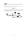
Application Note: 9901
Transformer Characterisation
Using External Low Bias Current
!
Wayne Kerr Electronics Limited
Introduction
There is an increasing demand for telecommunications devices such as mobile phones and modems.
With this comes an increasing demand on component manufacturers to produce telecomm components.
The area of interest in this application note is telecomms transformers. Transformers used in modems
will quite often be used in circuits where a small DC current will pass through the primary winding.
For transformer manufacturers, it is often imperative that their transformers are tested in a way that
simulates the intended operating conditions. Using the technique described in this application note it is
possible to provide an extremely accurate DC bias current, which can be used to simulate in-circuit
operation. This application note is written around a worked example and it explains how to make an
external DC bias current device. The aim is to give an understanding of the external bias design so that
it can be modified to suit any low DC bias current application.
The technique described uses a 3260A Precision Magnetics Analyser. The same technique can be used
in conjunction with the 3255 Inductance Analyser.
Figure 1 below shows an example test set-up using and external bias current.
Figure 1.
Low bias currents
It is common for telecomms transformers to have a small DC current flowing through the primary
winding. It is important that when transformers are tested, the effects of any current (that will be
present when the device is in circuit) are taken into account.
In some telecomm transformers the effect of the DC current can be quite significant and a very small
variation in the DC current (a few micro amps up or down) can have dramatic effects on the
transformers characteristics. For this reason, transformers that will be used with a DC current flowing
though the primary need to be tested under the same conditions.
The PMA3260A can be used to provide a DC bias current between 1mA and 1A. Although the lower
current limit is 1mA, it is not always possible to deliver low level DC bias current with enough
accuracy for all applications. However, using the technique detailed in this application note it is
relatively easy to obtain a level of current accuracy that is adequate for most applications.
Page 1 of 8
Safety Warning
WARNING Back EMF!
Lethal back EMF potentials can be generated if an inductor under test is disconnected whilst
current is still flowing in it. This warning is applicable even at the relatively low currents covered
in this application note.
NEVER touch the test connections while the direct current is flowing.
ALWAYS USE a Safety Interlock, see Appendix 1 ‘Safety Interlock’.
Connections
The instrument connections to the DUT remain the same. The measurement leads however, need to be
intercepted to allow the external bias current to be introduced in to the circuit.
Figure 2 below, shows how the measurement leads connect with the external bias.
[DW2/27148] Four
way BNC link cable
PMA3260A
[1EVA40100]
Kelvin leads
External
Bias
Unit
OR
DUT
Connecting
Leads
IA3255
Voltage
Source
Ammeter
Figure 2.
Construction Details
Parts List
1 off General purpose metal box. (Choose size to suit requirement)
1 off 5kΩ Resistor 0.25 Watt (Current resistor) * †
2 off 10µF Capacitor 50V (Blocking capacitors for Drive High and Sense High) * †
1 off Single sided, strip board. (Choose size to suit requirement)
4 off 4mm sockets
8 off BNC bulkheads. (Non-insulated)
4 off Insulating PCB pillars, nylon or similar
* Values are specific to each design. Please see the ‘Design Notes’ section for further information on
how to select these components.
† Tolerances not quoted, as the absolute value is not important.
Page 2 of 8
Additional Equipment
1 set of Kelvin leads (fine jaw) [1EVA40100]. Used to connect the external bias unit to the DUT.
1 set of Four way BNC link cable [DW2/27148]. Used to connect the test instrument to the external
bias unit.
2 sets of leads terminated in 4mm ‘banana’ plugs.
Stabilised power supply (Farnell LT30-1 used in worked example). See notes.
Ammeter (Keithley 2000 Multimeter used in worked example). See notes.
Design Notes
Figure 3.
Resistor R1
R1 in the circuit diagram above acts as a V-I converter. When selecting the value for R1 you should
consider the bias current required and the output range of the PSU. In this worked example 4k7Ω was
chosen, primarily because it was a readily available value but also because it required a relatively high
base drive voltage of 4.7V. This meant that to deliver the full range of required current, 1 to 2mA, the
voltage range required was 4.7-9.4V. This gave a large margin for fine adjustment of the voltage
therefore following the current to be set very accurately.
Calculations
Current required was 1-2mA. Voltage range of PSU 0-30V.
V = I R (R = V / I)
∴
R = 4.7 / 1*10-3
∴
R1 = 4.7*103Ω
= 4k7Ω
The power rating of R1 needed to be selected to allow for the maximum voltage available from the
PSU. This is because there is not a limiter on the PSU so the possibility of accidental over voltage
needed to be considered.
The maximum voltage available was 30V.
Before the power rating could be calculated, the current through R1 at 30V needed to be calculated.
Page 3 of 8
I=V/R
∴
I = 30 / 4.7*103
∴
I = 0.0064A
= 6.4mA
With this information, the power rating required for R1 could be calculated.
P=VI
∴
P = 30 * 6.4*10-3
∴
PR1 = 0.192W
= 192mW
A quarter watt resistor was chosen for this application so that the maximum power was always well
within the specification of the resistor.
Capacitors C1 and C2
C1 and C2 act as blocking capacitors to prevent the external bias flowing into the instrument. The
specification of the blocking capacitor, C2, is critical. C2 will have an effect on the measurement
accuracy of the instrument. C1 however is less critical and its value and type matches C2 purely for
simplicity of design. Both capacitors must be non-polarised. 10µF capacitors were used in this
application. The details of why these were chosen are shown in the calculations below.
Calculations
The impedance of C2 needed to be relatively low when compared with sense line input impedance,
which is approximately 4kΩ.
Z of 10µF Capacitor at 1kHz.
Z = 1 / (2πfC)
∴
Z = 1 / (2 * π * 1000 * 10*10-6)
∴
Z ≅ 16Ω
This introduced a negligible magnitude error and a phase error of approximately 0.4%.
Design Note: If the required frequency is higher than 1kHz then a 10µF capacitor will still be suitable.
This is because as the frequency goes up, the impedance of the capacitor will reduce, therefore
reducing the phase error. However, should the requirement be for a frequency lower than 1kHz then
another capacitor value should be chosen. The impedance should be kept to 16Ω or less.
e.g. If a frequency of 500Hz is required.
The target impedance is 16Ω. So by rearranging the impedance formula in terms of capacitance we
can calculate the required capacitor value.
C = 1 / (2πfZ)
∴
C = 1 / (2 * π * 500 * 16)
Page 4 of 8
∴
C = 1 / (50265.48)
∴
C = 1.989*10-5
≅ 20µF
The voltage rating of the capacitors needed to be enough to take the maximum voltage that the PSU
could deliver. In this application example, the upper voltage of the PSU was 30V so the capacitors
chosen were rated at 50V, this gave ample operational margin.
Ammeter
It is very important to design and build the circuit to allow the ammeter to be connected in series with
the DUT. This will give the most accurate reading of the current at the DUT. It is also important to use
a suitably accurate (preferably) digital ammeter.
Power Supply
The power supply needs to meet certain requirements. It must have a stable, finely adjustable output. If
the voltage output fluctuates or does not have fine enough adjustment then the required current at the
DUT may be unobtainable. This situation will be made worse with an inaccurate ammeter. If possible,
a linear power supply should be used. If the only power supply available is switch mode then you need
to ensure that the switching frequency will not interfere with the measurement frequency.
Switches S1, S2 and S3
None of the switches shown in figure 3 are required for the basic operation of the external bias source.
However, S2 and S3 will allow certain operations to be performed that would otherwise require the
external bias source to be removed. In addition, though not required, switch S1 is recommended.
S1 Bias Current On/Off
Fitting a switch (single pole double throw) in the position marked S1 in figure 3 will allow the PSU
output to be disconnected from the circuit and connected directly across R1. This removes the need to
switch off the power supply for measurements with no bias current. Just switching off the power supply
may leave a small residual voltage, which could cause measurement errors.
S2 Internal Bias
Switch S2, when closed will short out the blocking capacitor in the drive high line. This will allow the
internal DC current bias to be used without removing the external bias source. IT IS IMPORTANT
TO NOTE THAT THE INTERNAL AND EXTERNAL DC CURRENT BIAS SHOULD NEVER
BE USED SIMULTANEOUSLY.
S3 DC Resistance
The final optional switch, S3, will allow DC resistance measurements. It will also allow an “all
frequency trim” to be performed, without having to remove the external bias source. This switch needs
to be used in conjunction with switch S2.
Page 5 of 8
Build Instructions
Figure 4 below shows a basic sketch of the assembled bias current box.
Figure 4.
1) The general-purpose case needs to be modified to accommodate the eight BNC connectors
required, four inputs and four outputs. The BNC connectors should then be fitted in such a way
that the outer, ground, connection makes a permanent contact with the case. The case will
therefore form the earth terminal and act as a shielding box.
2) The general-purpose case also needs to be modified to accommodate four 4mm connectors (or
similar). Two of the connectors will be used for the voltage input and two for the current
measurement. Mount the connectors either on the side of the case or on the lid. The voltage input
low terminal should be directly connected to the case, as this is a ground connection. However, all
of the other connections for the voltage source and the current measurement should be suitably
insulated from the case. Also at this stage, any of the optional switches that are required should be
mounted in the case.
3) The external bias circuit should be put together following the circuit sketched in figure 3. The
circuit can be built on strip board or similar prototype material. If a large number of bias boxes are
required then another method of producing the circuit boards may be feasible. Once constructed
the circuit board needs to be securely fitted in to the case. The board should be mounted in the box,
ideally on pillars, in such a way that the circuit cannot short out on the metal case. The ground
rail(s) should be connected to the case. An ideal way to do this would be to connect the ground
rail(s) to a tag on one of the BNC connectors or the Earth terminal 4mm socket.
4) At this point, the circuit board is ready to be wired in, all connections to the BNC’s and 4mm
connectors should be made. Any of the optional switches required should be wired in at this stage
of assembly.
5) Finally, fit the lid to the case and connect the bias source as described in the section called
‘Connections’.
Page 6 of 8
Test Procedure
Trimming
Before making any measurements with the external bias source connected, an open and short circuit
trim should be performed in the normal way. Both trims should be performed as “spot frequency
trims”. The reason for performing a “spot trim” being that an "all frequency trim" includes a trim at
DC. The blocking capacitors prevent DC measurements and will cause the trim to fail. Also since each
bias source will be designed for use over a very narrow, or even fixed, frequency range it is not
necessary to perform an all frequency trim.
Instrument set-up
Setting DC bias
Connect the ammeter into the circuit as indicated in figure 3, in series with the DUT. Adjust the voltage
to give the desired current and replace the ammeter with a shorting link.
Important note: If a different type of transformer is to be tested, then the voltage should be readjusted to obtain the
correct current for the particular DUT.
Setting measurement conditions
Note the following instrument set-up only applies for this particular example. Each bias box will
generally be designed to meet a specific specification. Therefore, each box will be designed to work
under the desired test conditions for the DUT.
Instrument should be set to: Frequency:
AC Drive Level:
Internal DC Bias:
External DC Bias:
Measurement Parameters:
Measurement Mode:
Range:
1kHz
0.1Vac
0A off
1-2mA. (Set by adjusting voltage source.)
L, Q, Series equivalent circuit, and Slow measurement speed.
Repetitive.
See notes below.
Range settings
This method of generating DC bias forces some restrictions on the ranges and drive levels available.
These restrictions are indicated in the table below.
Range
1
2
3
4
5
Impedance
Range
<1Ω
<10Ω
<50Ω
>50Ω
>250Ω
Drive Type
Idc max.
Vac max.
I drive
I drive
I drive
V drive
V drive
50mA
50mA
30mA
30mA
3mA
N/A
N/A
N/A
<0.5V
<0.5V
Page 7 of 8
Measurements
Once the instrument is set-up with the DUT in place, all of the required inductance measurements can
be taken in the usual way. Refer to the instrument user manual for more specific measurement
instructions.
If the readings are blanked by the application of the bias current, a range error has occurred. To
overcome this try reducing the drive level until the reading updates.
Appendix 1
For reasons of safety, an interlock should be used in conjunction with the external bias. The diagram
below shows the diagram as recommended for internal bias protection. This can easily be adapted for
external bias. Ideally, the DUT should be housed within a box that has an interlock door. For further
details please refer to you user manual.
Figure 5.
Page 8 of 8